JP4796554B2 - motor - Google Patents
motor Download PDFInfo
- Publication number
- JP4796554B2 JP4796554B2 JP2007205713A JP2007205713A JP4796554B2 JP 4796554 B2 JP4796554 B2 JP 4796554B2 JP 2007205713 A JP2007205713 A JP 2007205713A JP 2007205713 A JP2007205713 A JP 2007205713A JP 4796554 B2 JP4796554 B2 JP 4796554B2
- Authority
- JP
- Japan
- Prior art keywords
- sleeve
- plate
- shaft
- cap
- motor
- Prior art date
- Legal status (The legal status is an assumption and is not a legal conclusion. Google has not performed a legal analysis and makes no representation as to the accuracy of the status listed.)
- Expired - Fee Related
Links
Images


Classifications
-
- H—ELECTRICITY
- H02—GENERATION; CONVERSION OR DISTRIBUTION OF ELECTRIC POWER
- H02K—DYNAMO-ELECTRIC MACHINES
- H02K5/00—Casings; Enclosures; Supports
- H02K5/04—Casings or enclosures characterised by the shape, form or construction thereof
- H02K5/16—Means for supporting bearings, e.g. insulating supports or means for fitting bearings in the bearing-shields
- H02K5/167—Means for supporting bearings, e.g. insulating supports or means for fitting bearings in the bearing-shields using sliding-contact or spherical cap bearings
- H02K5/1675—Means for supporting bearings, e.g. insulating supports or means for fitting bearings in the bearing-shields using sliding-contact or spherical cap bearings radially supporting the rotary shaft at only one end of the rotor
Description
本発明は、モータ(Motor)に関する。 The present invention relates to a motor.
一般的に、スピンドルモータ(Spindle motor)は、プロジェクションTV、ホームシアター装備、コンピュータ用ドライブなど精密回転装置を必要とする電子製品に広く使用されている。スピンドルモータは、サイズが小さく、高速回転が可能であり、精密制御が容易く、消費電力が少ないという点など、長所が多いので今後その使用が増大される見込みである。 Generally, a spindle motor is widely used in electronic products that require a precision rotating device such as a projection TV, home theater equipment, and a computer drive. The spindle motor has many advantages such as small size, high speed rotation, easy precise control, and low power consumption, so its use is expected to increase in the future.
しかし、従来のベアリング構造を有するスピンドルモータの場合、ベアリングを含浸させるオイルが外部に流出されてその機能を低下させる要因として作用する。オイルが流出されると、高速回転機能に問題が発生することになり、高温状態での摩擦により摩耗が生じる。このような状態が持続されると、スピンドルモータの寿命が減少し、騷音と振動が増加して使用上の不便をもたらすだけでなく、スピンドルモータを装着した電子製品の全体動作に異常機能をもたらすことになる。 However, in the case of a spindle motor having a conventional bearing structure, oil impregnating the bearing flows out to the outside and acts as a factor of reducing its function. When the oil flows out, a problem occurs in the high-speed rotation function, and wear occurs due to friction in a high temperature state. If this condition persists, the life of the spindle motor will be reduced, and noise and vibration will increase, causing inconvenience in use, as well as abnormal functions in the overall operation of electronic products equipped with the spindle motor. Will bring.
よって、オイルの流出の防止、すなわち、シール(Seal)性能を改善する必要性が提起されている。 Therefore, there is a need to prevent oil spillage, that is, to improve seal performance.
本発明は、突起とプレートの平面との間に流体ベアリングの漏洩を防止するラジアルシール(radial seal)を形成し、スリーブに連通孔を形成することにより高い安全性と高いシール(Seal)効果を持つモータを提供する。 In the present invention, a radial seal that prevents leakage of the fluid bearing is formed between the protrusion and the plane of the plate, and a communication hole is formed in the sleeve, so that high safety and a high seal effect are achieved. Provide a motor with.
本発明の一実施形態によれば、固定部材と、固定部材と結合されて仮想の回転軸を中心として回転する回転部材と、回転部材を支持するように、回転部材に結合または取り付けられるプレートと、プレートの間にベアリング空間が形成されるようにプレートの少なくとも一部をカバーするキャップと、及びベアリング空間に介在されるキャップベアリングとを含むモータが提供される。 According to an embodiment of the present invention, a fixing member, a rotating member that is coupled to the fixing member and rotates about a virtual rotation axis, and a plate that is coupled or attached to the rotating member so as to support the rotating member; A motor is provided that includes a cap that covers at least a portion of the plate such that a bearing space is formed between the plates, and a cap bearing interposed in the bearing space.
固定部材と回転部材の一側面をカバーするベースカバーが追加で結合されることができ、ベースカバーは加圧により固定部材または回転部材に接するように弾性変形される材質からなることが好ましい。 A base cover that covers one side of the fixing member and the rotating member may be additionally coupled, and the base cover is preferably made of a material that is elastically deformed so as to come into contact with the fixing member or the rotating member by pressing.
固定部材は貫通ホールが形成されたスリーブであり、回転部材は貫通ホールに挿入されるシャフト、またはシャフトを含む結合体であってもよく、プレートはシャフトの断面に相応する第1ホールを備え、シャフトが第1ホールに挿入されるようにシャフトと結合されてスリーブの一側面に取り付けられるドーナツ形状であってもよい。 The fixing member may be a sleeve having a through hole formed therein, the rotating member may be a shaft inserted into the through hole, or a combined body including the shaft, and the plate may include a first hole corresponding to a cross section of the shaft, The donut shape may be attached to one side of the sleeve by being coupled to the shaft so that the shaft is inserted into the first hole.
キャップは、プレートの外周面及び平面をカバーする方がよく、プレートの平面をカバーする部分にプレートを向いて突出される突起が形成されることがよい。 The cap preferably covers the outer peripheral surface and the flat surface of the plate, and a protrusion that protrudes toward the plate may be formed in a portion that covers the flat surface of the plate.
ベアリング空間を区画するキャップの内周面は、凹状の曲面を含む方がよい。 The inner peripheral surface of the cap that defines the bearing space should preferably include a concave curved surface.
一方、キャップに形成される突起は凸状の曲面であり、突起とキャップの内周面とは曲面で繋がる方がよく、突起とプレートの平面との間にはキャップベアリングの漏洩を防止するラジアルシール(radial seal)が形成されることがよい。 On the other hand, the protrusion formed on the cap is a convex curved surface, and it is better to connect the protrusion and the inner peripheral surface of the cap with a curved surface, and the radial between the protrusion and the flat surface of the plate prevents leakage of the cap bearing. A seal may be formed.
スリーブには、プレート及びキャップが取り付けられるスリーブの一側面が陥入、または突出されるようにするステップトエッジ(stepped edge)を形成して、締結を堅固にすることができる。 The sleeve can be formed with a stepped edge that allows one side of the sleeve to which the plate and the cap are attached to be recessed or protruded to provide a firm fastening.
一方、プレートとスリーブとの間の隙間には、キャップベアリングに繋がる第1スラスト(thrust)ベアリングが介在されてもよく、スリーブとシャフトとの間の隙間には、第1スラストベアリングに繋がるラジアル(radial)ベアリングが介在され、スリーブとベースカバーとの間の隙間にはラジアルベアリングに繋がる第2スラスト(thrust)ベアリングが介在されてもよい。 Meanwhile, a first thrust bearing connected to the cap bearing may be interposed in a gap between the plate and the sleeve, and a radial ( A radial bearing may be interposed, and a second thrust bearing connected to the radial bearing may be interposed in the gap between the sleeve and the base cover.
第1スラストベアリングと第2スラストベアリングとは連通孔により繋がる方がよく、連通孔は上記スリーブを貫通して形成されてもよい。 The first thrust bearing and the second thrust bearing are preferably connected by a communication hole, and the communication hole may be formed through the sleeve.
しかし、スリーブは貫通ホールが形成された内部スリーブと、内部スリーブを収容するように内部スリーブの外周面に結合される外部スリーブとに分けられ、内部スリーブと外部スリーブとの間の隙間に連通孔が形成されてもよい。 However, the sleeve is divided into an inner sleeve in which a through hole is formed and an outer sleeve coupled to the outer peripheral surface of the inner sleeve so as to accommodate the inner sleeve, and a communication hole is formed in the gap between the inner sleeve and the outer sleeve. May be formed.
この場合、連通孔は外部スリーブに形成され、外部スリーブの内周面に長さ方向で形成される溝形状であることが好ましい。 In this case, the communication hole is preferably formed in the outer sleeve and has a groove shape formed in the length direction on the inner peripheral surface of the outer sleeve.
本発明の別の実施形態によれば、固定部材と、固定部材と結合されて仮想の回転軸を中心として回転する回転部材と、回転部材を支持するように回転部材に結合、または取り付けられるプレートと、回転部材と固定部材の一側面をカバーするベースカバーと、プレートの少なくとも一部をカバーするキャップと、を含み、キャップとプレートとの間に、プレートと固定部材との間に、固定部材と回転部材との間に、回転部材とベースカバーとの間に繋がる空間に連続的に充填される流体を含むことを特徴とするモータが提供される。 According to another embodiment of the present invention, a fixing member, a rotating member that is coupled to the fixing member and rotates about a virtual rotation axis, and a plate that is coupled to or attached to the rotating member so as to support the rotating member And a base cover that covers one side surface of the rotating member and the fixing member, and a cap that covers at least a part of the plate, and the fixing member between the cap and the plate and between the plate and the fixing member. There is provided a motor including a fluid continuously filling a space connected between the rotating member and the rotating member.
固定部材は貫通ホールが形成されたスリーブを含み、回転部材は貫通ホールに挿入されるシャフトを含むし、プレートはシャフトの断面に相応する第1ホールを備え、シャフトが第1ホールに挿入されるようにシャフトと結合されてスリーブの一側面に取り付けられるドーナツ形状であってもよい。 The fixing member includes a sleeve having a through hole formed therein, the rotating member includes a shaft inserted into the through hole, the plate includes a first hole corresponding to a cross section of the shaft, and the shaft is inserted into the first hole. Thus, it may be a donut shape that is coupled to the shaft and attached to one side of the sleeve.
一方、キャップはプレートの外周面及び平面をカバーする形状であってもよく、キャップがプレートの平面をカバーする部分にプレートを向いて突出される突起が形成されてもよい。また、キャップの内周面には凹状の曲面が形成されてもよい。 On the other hand, the cap may have a shape that covers the outer peripheral surface and the plane of the plate, and a protrusion that protrudes toward the plate may be formed in a portion where the cap covers the plane of the plate. A concave curved surface may be formed on the inner peripheral surface of the cap.
突起とプレートの平面との間には、流体の漏洩を防止するラジアルシール(radial seal)が形成されてもよい。 A radial seal may be formed between the protrusion and the plane of the plate to prevent fluid leakage.
上述したことの以外の異なる側面、特徴、利点が以下の図面、特許請求の範囲を含む発明の詳細な説明により明確になるだろう。 Different aspects, features, and advantages than those described above will become apparent from the following detailed description of the invention, including the drawings and the claims.
本発明の好ましい実施例によるモータは、突起とプレートの平面との間に流体ベアリングの漏洩を防止するラジアルシール(radial seal)を形成し、スリーブに連通孔を形成することにより高い安全性と高いシール(Seal)効果を提供することができる。 In the motor according to the preferred embodiment of the present invention, a radial seal that prevents the fluid bearing from leaking is formed between the projection and the plane of the plate, and a communication hole is formed in the sleeve, so that the safety is high. A seal effect can be provided.
以下、本発明によるモータの好ましい実施例を添付図面を参照して詳しく説明するが、添付図面を参照して説明することにおいて、同一であるか対応する構成要素は等しい図面番号を付与し、これに対する重複される説明は略する。 Hereinafter, preferred embodiments of a motor according to the present invention will be described in detail with reference to the accompanying drawings. In the description with reference to the accompanying drawings, the same or corresponding components are given the same drawing number, and The overlapping explanation for is omitted.
一般的にモータは、回転部材と、回転部材の回転運動を支持する固定部材と、及び回転部材と固定部材との間に介在されるベアリングと、を基本として含む。例えば、回転部材としては、シャフト及びシャフトに結合されて共に回転するハブ、プレートなどの結合体があり、固定部材としては、シャフトを取り囲むスリーブなどがある。 Generally, a motor basically includes a rotating member, a fixed member that supports the rotational movement of the rotating member, and a bearing that is interposed between the rotating member and the fixed member. For example, the rotating member includes a shaft and a combined body such as a hub and a plate that are coupled to the shaft and rotate together, and the fixing member includes a sleeve that surrounds the shaft.
しかし、回転部材と固定部材とは、構成要素自体により決定されるものではなく、設計により行われる機能に応じて決定されるものである。すなわち、シャフトが固定され、シャフトを取り囲むスリーブが回転する場合もあり、この場合にはシャフトが固定部材となり、スリーブが回転部材となる。 However, the rotating member and the fixing member are not determined by the components themselves, but are determined according to the functions performed by design. That is, the shaft is fixed, and the sleeve surrounding the shaft may rotate. In this case, the shaft becomes the fixing member and the sleeve becomes the rotating member.
以下で説明する本発明の複数の実施例では、固定部材としてスリーブを、回転部材としてシャフト及びこれに結合されるプレートとハブとを提示し、これを基準として説明する。 In a plurality of embodiments of the present invention described below, a sleeve is provided as a fixed member, a shaft as a rotating member, a plate coupled to the shaft, and a hub are presented and described as a reference.
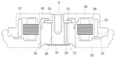
図1は、本発明の好ましい第1実施例によるモータの構造を示す断面図であり、図2は、図1の「A」部分を拡大した拡大断面図であり、図3は、図2の「B」部分を拡大した拡大断面図である。図1ないし図3を参照すると、シャフト10、ベースカバー20、スリーブ30、連通孔37、貫通ホール39、キャップ40、突起41、プレート50、ハブ60、キャップベアリング73、ラジアルシール(radial seal)75、永久磁石91、ベース95、マグネット97、電磁石部99が示されている。
FIG. 1 is a cross-sectional view showing a structure of a motor according to a first preferred embodiment of the present invention, FIG. 2 is an enlarged cross-sectional view of an “A” portion of FIG. 1, and FIG. It is the expanded sectional view which expanded "B" part. 1 to 3, the
シャフト10は、回転運動の中心軸であって、追後説明するハブ60と結合されてハブ60と一体で回転することができ、以下で説明するスリーブ30の貫通ホール39に挿入される。
The
スリーブ30は、シャフト10の外周面をカバーしてシャフト10の回転運動を 安定的に維持させる手段である。スリーブ30の内部には、シャフト10が挿入できるように貫通ホール39が形成されており、シャフト10が貫通ホール39に挿入されカバーされることにより、回転運動時にスリーブ30により支持されることができる。スリーブ30とシャフト10との間の隙間には、以下で説明するラジアル(radial)ベアリングが介在される。
The
ラジアルベアリング74は、流体ベアリングであって、スリーブ30とシャフト10との間の隙間に介在され、シャフト10が回転運動時にシャフト10を支持してシャフト10の回転運動を安定的に維持することができる。ラジアルベアリング74は、シャフト10とスリーブ30との間の隙間にオイル(oil)を注入することで形成することができる。一方、本実施例ではラジアルベアリング74としてオイル(oil)を提示したが、設計上の必要により多様に変更することができる。
The
一方、ラジアルベアリングの作動効率を高めるために、図7に示すように、シャフトの表面に動圧溝12が形成されてもよい。動圧溝12により、モータの作動時にラジアルベアリングをなす流体の流れを所定方向に誘導できるようになり、このような流体の流れにより流体圧、すなわち、動圧をより効率的に提供することができる。
On the other hand, in order to increase the operating efficiency of the radial bearing, a
このような動圧溝12は、エッチングのような化学的方法を用いて形成してもよく、レーザ加工などのような物理的方法を用いて形成してもよい。また、動圧溝はヘリングボーン(herringbone)の形状、またはスパイラル(spiral)形状に形成されてもよい。
Such a
本実施例では、動圧溝12がシャフトの表面に形成される場合を提示したが、動圧溝を、シャフトと対向するスリーブの内壁に形成してもよく、動圧溝の模様と大きさ及び個数などは必要により多様に変更して適用することができる。
In this embodiment, the case where the
ベースカバー20は、シャフト10の他側で貫通ホール39をカバーできる手段であって、スリーブ30の一側面に結合され、ベースカバー20が結合されるスリーブ30の一側面の形状に相応する形状からなることができる。
The
一方、ベースカバー20は弾性変形される材質を含んで形成される。これにより、本実施例によるモータを組み立てる過程において、ベースカバー20に支持荷重をかけて、シャフト10がスリーブ30の貫通ホール39に容易くて精密に挿入されるようにすることができる。ベースカバー20とスリーブ30との間の隙間には、以下で説明する第2スラスト(thrust)ベアリングが介在されることができる。
On the other hand, the
第2スラスト(thrust)ベアリングは、流体ベアリングであって、ベースカバー20とスリーブ30との間の隙間に介在され、シャフト10を軸方向に支持し、シャフト10の円滑な回転運動を維持できるようにする。
The second thrust bearing is a fluid bearing and is interposed in a gap between the
第2スラスト(thrust)ベアリングは、スリーブ30とベースカバー20との間の隙間にオイル(oil)を注入することにより形成することができ、上述したラジアルベアリング74に繋がる。すなわち、スリーブ30とベースカバー20との間の隙間と、スリーブ30とシャフト10との間の隙間とは、互いに連通されて、それぞれに注入されるオイルは自由に流動し循環できるようになる。一方、本実施例では第2スラストベアリング72としてオイルを提示したが、設計上の必要により多様に変更することができる。
The second thrust bearing can be formed by injecting oil into the gap between the
一方、第2スラストベアリングの作動効率を高めるために、ベースカバーと対向するスリーブの内壁、またはベースカバーの表面に動圧溝(図示せず)が形成されてもよい。動圧溝(図示せず)により、モータを作動する際に第2スラストベアリングの流体の流れを所定方向に誘導することができ、このような流体の流れにより流体圧、すなわち、動圧をより効率的に提供できるようになる。このような動圧溝の形成方法及びその形状は前の説明と類似であるため、これに対する説明は略する。 On the other hand, in order to increase the operating efficiency of the second thrust bearing, a dynamic pressure groove (not shown) may be formed on the inner wall of the sleeve facing the base cover or on the surface of the base cover. A dynamic pressure groove (not shown) can guide the fluid flow of the second thrust bearing in a predetermined direction when the motor is operated, and the fluid pressure, that is, the dynamic pressure is further increased by the fluid flow. It can be provided efficiently. Since the formation method and the shape of such a dynamic pressure groove are similar to the previous description, the description thereof will be omitted.
プレート50は、中央にシャフト10の断面に相応する第1ホールを備えるドーナツ形状であってもよい。第1ホールにはシャフト10が挿入され結合されるし、プレート50の一側面はスリーブ30の一側面に取り付けられる。
The
プレート50は、シャフト10とは別に製造されてシャフト10に結合されてもよいし、製造時からシャフト10と一体に形成されてもよく、シャフト10の回転運動時にシャフト10と共に回転運動することになる。プレート50とスリーブ30との間の隙間には、以下で説明する第1スラスト(thrust)ベアリングが介在されてもよい。
The
第1スラスト(thrust)ベアリングは、流体ベアリングであって、プレート50とスリーブ30との間の隙間に介在されてもよく、プレート50を支持し、プレート50の回転運動時プレート50とスリーブ30との間の摩擦を減らすことができ、安定的な運動を維持できるようにする。
The first thrust bearing may be a fluid bearing and may be interposed in a gap between the
一方、第1スラストベアリングの作動効率を高めるために、プレートと対向するスリーブの上面またはプレートの下面に動圧溝(図示せず)が形成されてもよい。動圧溝(図示せず)により、モータの作動時第1スラストベアリングの流体の流れを所定方向に誘導することができ、このような流体の流れにより流体圧、すなわち、動圧をより効率的に提供できるようになる。このような動圧溝の形成方法及びその形状は、前の説明と類似であるのでこれに対する説明は略する。 On the other hand, in order to increase the operating efficiency of the first thrust bearing, a dynamic pressure groove (not shown) may be formed on the upper surface of the sleeve facing the plate or the lower surface of the plate. A dynamic pressure groove (not shown) can guide the fluid flow of the first thrust bearing in a predetermined direction when the motor is operated, and the fluid pressure, that is, the dynamic pressure is more efficiently generated by such a fluid flow. Will be able to provide. Since the method for forming such a dynamic pressure groove and its shape are similar to the previous description, the description thereof will be omitted.
第1スラスト(thrust)ベアリングは、プレート50とスリーブ30との間の隙間にオイル(oil)を注入することにより形成できるし、上述したラジアルベアリング74に繋がる。すなわち、プレート50とスリーブ30との間の隙間と、スリーブ30とシャフト10との間の隙間とは互いに連通され、それぞれに注入されるオイルは自由に流動して循環できるようになる。これにより、第1スラストベアリング71とラジアルベアリング74及び第2スラストベアリング72は、すべて繋れることができる。一方、本実施例では、第1スラストベアリング71としてオイルを提示したが、設計上の必要により多様に変更することができる。
The first thrust bearing can be formed by injecting oil into the gap between the
キャップ40は、プレート50の外周縁部45との間にベアリング空間が形成されるようにプレート50の外周面及び一側面をカバーしながら、スリーブ30の一側面に取り付けられる。ここで、プレート50の外周縁部とは、プレート50の一側面の外周部と外周面とを含むプレート50の角部分を意味し、図3の参照番号45により明確に確認できる。
The
キャップ40は、キャップが取り付けられるスリーブ30の一側面の形状に相応する形状を有する。これに対する具体的な例は、後にスリーブ30の一側面の形状を説明しながら並行することにする。
The
一方、キャップのプレート50の一側面をカバーする部分には、プレート50を向いて突出される突起41が形成されてもよい。突起41が形成されることによりキャップ40とプレート50の一側面との間の隙間は、プレート50の直径方向に所定位置で最小となり、最小となる地点を基準として上記隙間が再び増加する形状を有する。
On the other hand, a
突起41により、キャップ40とプレート50の一側面との間の隙間が最小となる地点を形成することができ、これにより、後に説明するキャップベアリング73をなす流体の漏洩を減少することができるし、また流体の流れも制御できるようになる。キャップベアリング73をなす流体の流れに対しては、後で具体的に説明する。
The
また、突起41は凸状の曲面で形成され、ベアリング空間を区画するキャップの内周面に曲面で繋がる。突起41を凸状の曲面で緩く形成することにより、以下で説明するキャップベアリング73をなす流体の流動を円滑にすることができるようになり、究極的にモータの回転運動を安定的に維持することができる。
The
一方、プレート50の外周縁部45とキャップにより区画されるベアリング空間にはキャップベアリング73が介在される。
On the other hand, a
キャップベアリング73は、流体ベアリングであって、ベアリング空間にオイル(oil)を注入して形成することができ、上述した第1スラストベアリング71に繋がる。すなわち、プレート50とスリーブ30との間と、ベアリング空間とは互いに連通され、それぞれに注入されるオイルは自由に流動して循環できるようになる。これにより、第1スラストベアリング71とラジアルベアリング74、第2スラストベアリング72及びキャップベアリング73は、すべて繋がることになる。一方、本実施例ではキャップベアリング73のものとしてオイルを提示したが、設計上の必要により多様に変更することができる。
The
キャップベアリング73は、プレート50の外周面と一側面とを支持し、プレート50の回転運動を安定的に維持することができる。このようなキャップベアリングの機能に対して以下でより具体的に説明する。
The
モータが作動すると、第1スラストベアリング71によりプレート50に動圧が提供され、これによりプレート50は浮上する。このようなプレートの浮上は、モータの作動を不安定にする要因となり得る。
When the motor is operated, dynamic pressure is provided to the
このように、プレートが浮上する場合、キャップ40により形成されるベアリング空間に存在する流体(本実施例の場合オイル)の一部は、キャップの凹状の曲面によりプレートより相対的に上側に位置することができ、これによりプレートの浮上を阻止する方向に圧力を供給できるようになる。すなわち、キャップにより形成されるベアリング空間に存在する流体により、プレートは支持されることができる。これにより、プレートは回転運動を安定的に維持できるようになる。
Thus, when the plate floats, a part of the fluid (oil in this embodiment) existing in the bearing space formed by the
このようにキャップ40により形成されるベアリング空間に存在する流体は、プレート50を支持するベアリングとしての機能をすることもできる。しかし、これだけでなく、第1スラストベアリング71をなす流体が蒸発などにより消失される場合、これを補充して供給することができる流体貯蔵所としての機能もすることができる。
Thus, the fluid existing in the bearing space formed by the
一方、突起41とプレート50の平面との間には、キャップベアリング73をなすオイルの漏洩を防止するためにラジアルシール(radial seal)75が形成される。ラジアルシール75は、突起41とプレート50の平面との間に形成されてキャップベアリング73をなすオイルの漏洩を防止する栓の役目をする。本実施例によれば、オイルと異なる物質で形成されるものではなく、上述したキャップの形状に応じて毛細管現象及び表面張力を用いることによりオイルの漏洩を防止することができる。
On the other hand, a
ハブ60は、シャフト10の一側に結合され、シャフト10の軸と垂直する方向に延長されて形成されてもよい。ハブ60は、永久磁石91と電磁石部99とを含む動力発生手段から動力の伝達を受けて回転運動をすることができ、ハブ60の回転運動によりシャフト10も回転運動をすることができる。
The
図1の実施例では、動力発生手段としてハブ60と結合された永久磁石91及び永久磁石91に隣接して形成された電磁石部99を提示したが、動力発生手段を構成する構成要素及び各構成要素の結合位置は、設計上の必要により多様に変更することができる。
In the embodiment of FIG. 1, the
一方、ハブ60の外周面には、必要により多様な回転体が結合されてもよい。例えば、LSU(Laser Scanning Unit)である場合には回転多面鏡が結合されてもよく、ハードディスクドライブである場合にはディスクが結合されてもよい。
On the other hand, various rotating bodies may be coupled to the outer peripheral surface of the
さらに、図1を参照すると、ハブの端部に結合された永久磁石91に隣接してマグネット97が結合される。この時、マグネット97はハブ60に結合された永久磁石91と互いに引力が発生するように着磁される。これを通して、ハブ60はプレート50に圧力をかけることができるようになり、モータが安定的に作動することができる。このようなモータの作動に対しては、後で具体的に説明する。
Still referring to FIG. 1, a
スリーブ30は、上述したようにシャフト10の外周面をカバーしてシャフト10の安定的な回転運動を維持することができる手段である。スリーブ30の内部にはシャフト10が挿入できるように貫通ホール39が形成され、シャフト10が貫通ホール39に挿入されてカバーされることにより回転運動時スリーブ30によりその外周面が支持される。
As described above, the
一方、スリーブ30には、プレート50及びキャップが取り付けられる一側面が突出されるようにステップトエッジ(stepped edge)31が形成されてもよく、または、プレート50及びキャップが取り付けられる一側面が陥入されるようにステップトエッジ(stepped edge)32が形成されてもよい。このようなスリーブ30の一側面の形状に相応するようにキャップが形成されてもよい。
Meanwhile, the
図3を参照すると、プレート50及びキャップが取り付けられるスリーブ30の一側面が突出されるようにステップトエッジ31が形成されていることを確認できる。このようなスリーブ30の形状に相応してキャップはプレート50の外周面部及びステップトエッジをすべてカバーする形状で形成されている。これにより、スリーブ30とプレート50及びキャップの結合を容易に行うことができ、かつ堅固に結合されることができる。
Referring to FIG. 3, it can be confirmed that the stepped
別の実施例として、図6を参照すると、プレート50及びキャップが取り付けられるスリーブの一側面が陥入されるようにステップトエッジ32が形成されたことを確認できる。このようなスリーブの形状に相応して、キャップ40'はプレート50の外周面部をカバーし、キャップ40'の外周面はステップトエッジ32によりカバーされる形状で形成されている。これにより、スリーブ30とプレート50及びキャップ40'の結合を容易に行うことができ、かつ堅固な結合が可能となる。
As another example, referring to FIG. 6, it can be confirmed that the stepped
スリーブ30の所定位置には、第1スラストベアリング71と第2スラストベアリング72とを連結する連通孔37が形成される。連通孔37を通して第1スラストベアリング71をなすオイルと第2スラストベアリング72をなすオイルが円滑に循環できるので、モータ内部の各流体ベアリングに発生する圧力を均一化することができ、かつ内部に存在する気泡などを、循環により排出しやすいラジアルシール75部位に移動させることもできる。図6の点線矢印は、気泡の移動方向を示す。これによりモータの安定性を向上させることができる。
A
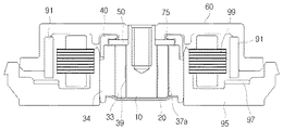
別の実施例として、図4を参照すると、スリーブ30は貫通ホール39が形成された内部スリーブ33と、内部スリーブを収容するように内部スリーブの外周面に結合される外部スリーブ34とを含み、内部スリーブ33と外部スリーブ34との間の隙間に連通孔37aが形成されたモータが示されている。
As another example, referring to FIG. 4,
内部スリーブ33の材質または構造的特性のため、加工により貫通ホール39を形成しにくい場合、内部スリーブ33及び、内部スリーブを収容するように内部スリーブの外周面に結合される外部スリーブ34が形成されるようにし、内部スリーブ33と外部スリーブ34との間の隙間に連通孔37aが形成されるようにする。このような構造を通しても上述したような、連通孔37を形成して得られる効果を示すことができる。
If it is difficult to form the through-
さらに別の実施例として、図5を参照すると、外部スリーブ34に連通孔37bを形成し、外部スリーブ34の内周面に長さ方向で溝を形成することにより連通孔37bを形成したモータを提供することができる。外部スリーブ34の内周面に溝を形成して内部スリーブ33と結合することだけでも連通孔37bを形成することができるので、連通孔37bの形成工程を単純化することができる。溝の形状及び形成位置は、設計上の必要により多様に変更することができる。
As yet another embodiment, referring to FIG. 5, a motor having a communication hole 37b formed by forming a communication hole 37b in the
この他にも、外部スリーブ34を貫通する連通孔を形成することができる。
In addition, a communication hole penetrating the
一方、上記したように、キャップ40とプレート50との間のベアリング空間に介在する流体と、プレート50とスリーブ30との間の第1スラストベアリング71をなす流体と、シャフト10とスリーブ30との間のラジアルベアリング74をなす流体と、シャフト10とベースカバー20との間の第2スラストベアリング72をなす流体とは互いに繋がる。互いに繋がって循環できるようになり、圧力を均一化する効果などを示すことができる。
On the other hand, as described above, the fluid interposed in the bearing space between the
これをより効率的に行うために、キャップ40とプレート50との間と、プレート50とスリーブ30との間と、シャフト10とスリーブ30との間と、シャフト10とベースカバー20との間とに繋がる空間に流体を連続的に充填することができる。すなわち、流体が注入されることができる空間に流体を持続的に充填する(full fill)ことにより、流体間の循環が円滑に行われるようにし、流体による圧力が均一に維持されることができる。
In order to do this more efficiently, between the
次に、本実施例によるモータの作動に対して説明する。 Next, the operation of the motor according to this embodiment will be described.
図3の(a)は、本実施例によるモータの停止時キャップベアリング73を示す断面図であり、(b)は本実施例によるモータの作動時キャップベアリング73を示す断面図である。
3A is a cross-sectional view showing the
本実施例によるモータが作動すると、ハブ60、シャフト10及びプレート50は回転運動をする。この時、プレート50は浮上し、これによりプレート50とスリーブ30との間の隙間が大きくなり、キャップベアリング73のオイルの一部がプレート50とスリーブ30との間の隙間に引っ張られて入ることになる。
When the motor according to the present embodiment is operated, the
これにより、ラジアルシール75もプレート50の外周縁方向に移動することになり、これはオイルの漏洩を防止するシール(Seal)効果が向上される結果に繋がる。
As a result, the
この場合、回転運動による遠心力が、さらにオイルにかけられて、シール(seal)効果はさらに向上されることができる。 In this case, the centrifugal force due to the rotational motion is further applied to the oil, so that the seal effect can be further improved.
一方、キャップの凹状の曲面に移動したオイルは、重力によりプレートの浮上を阻止する方向に加圧することとなる。これにより、プレートの浮上のため発生し得る不安定な作動を防止することができる。 On the other hand, the oil that has moved to the concave curved surface of the cap is pressurized in a direction that prevents the plate from floating due to gravity. As a result, it is possible to prevent an unstable operation that may occur due to the floating of the plate.
また、ハブの端部に結合された永久磁石と、永久磁石に隣接して介在されたマグネット97との間の引力により、プレートの浮上を抑制することができる。これにより、プレートの浮上のため発生し得る不安定な作動をさらに防止することができる。
Further, the floating of the plate can be suppressed by the attractive force between the permanent magnet coupled to the end of the hub and the
上記の実施形態の記載から明らかなように、本発明により下記モータが提供される。
固定部材と、固定部材と結合され、仮想の回転軸を中心として回転する回転部材と、回転部材を支持するように、回転部材に結合または取り付けられるプレートと、プレートとの間に所定空間が形成されるようにプレートの少なくとも一部をカバーするキャップと、プレートとキャップとの間の空間に介在される流体とを含むモータ。
As is apparent from the description of the above embodiment, the present invention provides the following motor.
A predetermined space is formed between the fixed member, the rotating member coupled to the fixing member and rotating about the virtual rotation axis, the plate coupled or attached to the rotating member so as to support the rotating member, and the plate. A motor including a cap that covers at least a portion of the plate, and a fluid interposed in a space between the plate and the cap.
また、上記モータにおいて、回転部材は、プレートの少なくとも一部に対して、仮想の回転軸の方向に当接するハブを含んでもよい。これにより、プレート浮上を防止する場合に、ハブおよびプレートを介して、回転部材をベースカバーに向かって効率よく押し付けることができる。 In the motor, the rotating member may include a hub that abuts at least a part of the plate in the direction of the virtual rotation axis. Thereby, when preventing plate floating, a rotation member can be efficiently pressed toward a base cover via a hub and a plate.
上述した実施例の以外に、多くの実施例が本発明の請求の範囲内に存在する。 In addition to the embodiments described above, many embodiments are within the scope of the present invention.
10 シャフト
12 動圧溝
20 ベースカバー
30 スリーブ
37 連通孔
40 キャップ
50 プレート
60 ハブ
71 第1スラストベアリング
72 第2スラストベアリング
73 キャップベアリング
74 ラジアルベアリング
75 ラジアルシール(radial seal)
DESCRIPTION OF
Claims (16)
前記貫通ホールに挿入されるシャフトと、
前記シャフトを支持するように、前記シャフトに結合または取り付けられるプレートと、
前記プレートとの間に所定空間が形成されるように前記プレートの上部表面及び外周面をカバーする内周面を有するキャップと、
前記プレートと前記キャップとの間の空間に介在される流体と、
前記キャップの前記内周面における前記プレートの上部表面をカバーする部分に形成され、前記プレートを向いて突出される突起と、
前記突起と前記プレートの平面との間の前記流体の毛細管現象及び表面張力によって形成され、前記流体の漏洩を防止するラジアルシール(radial seal)を含み、
前記突起は凸状の曲面であり、前記突起と前記キャップの内周面とは曲面で繋がり、
前記突起と前記プレートの前記上部表面との隙間は、前記プレートの直径方向の所定位置で最小となり、最小となる地点を基準として再び増加する形状を有することを特徴とするモータ。 A sleeve in which a through hole is formed;
A shaft inserted into the through hole;
A plate coupled or attached to the shaft to support the shaft;
A cap having an inner peripheral surface covering an upper surface and an outer peripheral surface of the plate so that a predetermined space is formed between the plate and the plate;
A fluid interposed in a space between the plate and the cap;
A protrusion formed on a part of the inner peripheral surface of the cap that covers an upper surface of the plate and protruding toward the plate;
A radial seal formed by capillary action and surface tension of the fluid between the protrusion and the plane of the plate to prevent leakage of the fluid;
The protrusion is a convex curved surface, and the protrusion and the inner peripheral surface of the cap are connected by a curved surface,
A motor having a shape in which a gap between the projection and the upper surface of the plate is minimized at a predetermined position in the diameter direction of the plate and increases again with a point where the gap is minimized as a reference.
前記スリーブと前記シャフトとの間の隙間には前記第1スラストベアリングに繋がるラジアル(radial)ベアリングが介在され、前記スリーブと前記ベースカバーとの間の隙間には前記ラジアルベアリングに繋がる第2スラスト(thrust)ベアリングが介在されることを特徴とする請求項10に記載のモータ。 A base cover for covering the sleeve and the other side of the shaft;
A radial bearing connected to the first thrust bearing is interposed in a gap between the sleeve and the shaft, and a second thrust ( The motor according to claim 10, further comprising a thrust bearing.
前記連通孔は、前記内部スリーブと前記外部スリーブとの間の隙間に形成されることを特徴とする請求項12に記載のモータ。 The sleeve includes an inner sleeve in which the through hole is formed, and an outer sleeve coupled to an outer peripheral surface of the inner sleeve so as to accommodate the inner sleeve,
The motor according to claim 12, wherein the communication hole is formed in a gap between the inner sleeve and the outer sleeve.
前記連通孔は、前記外部スリーブに形成されることを特徴とする請求項12に記載のモータ。 The sleeve includes an inner sleeve in which the through hole is formed, and an outer sleeve coupled to an outer peripheral surface of the inner sleeve so as to accommodate the inner sleeve,
The motor according to claim 12, wherein the communication hole is formed in the outer sleeve.
Applications Claiming Priority (4)
| Application Number | Priority Date | Filing Date | Title |
|---|---|---|---|
| KR20060074563 | 2006-08-08 | ||
| KR10-2006-0074563 | 2006-08-08 | ||
| KR10-2007-0016902 | 2007-02-20 | ||
| KR1020070016902A KR100868919B1 (en) | 2006-08-08 | 2007-02-20 | Motor |
Related Child Applications (1)
| Application Number | Title | Priority Date | Filing Date |
|---|---|---|---|
| JP2010151404A Division JP5217009B2 (en) | 2006-08-08 | 2010-07-01 | motor |
Publications (2)
| Publication Number | Publication Date |
|---|---|
| JP2008043197A JP2008043197A (en) | 2008-02-21 |
| JP4796554B2 true JP4796554B2 (en) | 2011-10-19 |
Family
ID=39050028
Family Applications (2)
| Application Number | Title | Priority Date | Filing Date |
|---|---|---|---|
| JP2007205713A Expired - Fee Related JP4796554B2 (en) | 2006-08-08 | 2007-08-07 | motor |
| JP2010151404A Expired - Fee Related JP5217009B2 (en) | 2006-08-08 | 2010-07-01 | motor |
Family Applications After (1)
| Application Number | Title | Priority Date | Filing Date |
|---|---|---|---|
| JP2010151404A Expired - Fee Related JP5217009B2 (en) | 2006-08-08 | 2010-07-01 | motor |
Country Status (2)
| Country | Link |
|---|---|
| US (1) | US7633200B2 (en) |
| JP (2) | JP4796554B2 (en) |
Families Citing this family (15)
| Publication number | Priority date | Publication date | Assignee | Title |
|---|---|---|---|---|
| JP2010078100A (en) * | 2008-09-26 | 2010-04-08 | Panasonic Corp | Fluid bearing device, spindle motor with the device, and information device |
| KR100997189B1 (en) * | 2008-11-14 | 2010-11-29 | 삼성전기주식회사 | Motor |
| KR101009153B1 (en) * | 2008-12-19 | 2011-01-18 | 삼성전기주식회사 | Spindle motor |
| KR101077427B1 (en) * | 2009-01-28 | 2011-10-26 | 삼성전기주식회사 | Spindle motor |
| KR101018224B1 (en) | 2009-01-28 | 2011-02-28 | 삼성전기주식회사 | Motor |
| KR101022891B1 (en) * | 2009-02-13 | 2011-03-16 | 삼성전기주식회사 | Spindle motor |
| KR101079480B1 (en) | 2009-11-11 | 2011-11-03 | 삼성전기주식회사 | spindle motor |
| KR101119256B1 (en) * | 2010-08-12 | 2012-03-16 | 삼성전기주식회사 | Spindle Motor |
| JP2012087861A (en) | 2010-10-19 | 2012-05-10 | Nippon Densan Corp | Fluid dynamic bearing mechanism, spindle motor and disk drive apparatus |
| KR101240863B1 (en) | 2010-12-29 | 2013-03-11 | 삼성전기주식회사 | Spindle motor |
| KR20130044687A (en) * | 2011-10-24 | 2013-05-03 | 삼성전기주식회사 | Spindle motor |
| KR101350601B1 (en) * | 2011-11-28 | 2014-01-16 | 삼성전기주식회사 | Spindle motor |
| KR20130072619A (en) * | 2011-12-22 | 2013-07-02 | 삼성전기주식회사 | Spindle motor |
| KR20130074571A (en) | 2011-12-26 | 2013-07-04 | 삼성전기주식회사 | Hydrodynamic bearing apparatus and spindlem motor having the same |
| KR20130088355A (en) * | 2012-01-31 | 2013-08-08 | 삼성전기주식회사 | Spindle motor |
Family Cites Families (11)
| Publication number | Priority date | Publication date | Assignee | Title |
|---|---|---|---|---|
| JP2596528Y2 (en) * | 1993-03-05 | 1999-06-14 | 中村 勝海 | Rotor support structure and rotary shaft support structure by motor air bearing |
| US5558445A (en) * | 1994-07-22 | 1996-09-24 | Quantum Corporation | Self-contained hydrodynamic bearing unit and seals |
| JP3601081B2 (en) | 1994-08-26 | 2004-12-15 | 日本電産株式会社 | Spindle motor |
| KR100274456B1 (en) | 1997-02-28 | 2000-12-15 | 이형도 | Herring bone type hydrodynamic bearing with spindle motor |
| SG94346A1 (en) * | 1999-12-23 | 2003-02-18 | Inst Data Storage | Spindle motor with an aerodynamic and hydrodynamic bearing assembly |
| JP2002054628A (en) * | 2000-08-08 | 2002-02-20 | Nippon Densan Corp | Dynamic pressure fluid bearing device and spindle motor |
| JP2002165407A (en) * | 2000-11-20 | 2002-06-07 | Nippon Densan Corp | Motor |
| JP2002354747A (en) * | 2001-05-21 | 2002-12-06 | Sony Corp | Spindle motor and disc storage device |
| JP4338359B2 (en) * | 2002-06-11 | 2009-10-07 | 日本電産株式会社 | Hydrodynamic bearing device |
| DE102004017356A1 (en) * | 2004-04-08 | 2005-11-10 | Minebea Co., Ltd. | Spindle motor with a hydrodynamic bearing system |
| JP4274476B2 (en) * | 2004-08-31 | 2009-06-10 | ミネベア株式会社 | Fluid dynamic pressure bearing, spindle motor equipped with the fluid dynamic pressure bearing, and recording disk drive |
-
2007
- 2007-08-02 US US11/882,587 patent/US7633200B2/en not_active Expired - Fee Related
- 2007-08-07 JP JP2007205713A patent/JP4796554B2/en not_active Expired - Fee Related
-
2010
- 2010-07-01 JP JP2010151404A patent/JP5217009B2/en not_active Expired - Fee Related
Also Published As
| Publication number | Publication date |
|---|---|
| US20080036302A1 (en) | 2008-02-14 |
| JP2008043197A (en) | 2008-02-21 |
| US7633200B2 (en) | 2009-12-15 |
| JP5217009B2 (en) | 2013-06-19 |
| JP2010226955A (en) | 2010-10-07 |
Similar Documents
| Publication | Publication Date | Title |
|---|---|---|
| JP4796554B2 (en) | motor | |
| KR100868919B1 (en) | Motor | |
| JP4418531B2 (en) | Fluid dynamic bearing device and spindle motor | |
| JP3652875B2 (en) | motor | |
| JP5335616B2 (en) | Fluid dynamic pressure bearing, spindle motor with fluid dynamic pressure bearing, and recording disk drive with spindle motor | |
| US8388227B2 (en) | Hydrodynamic bearing assembly and motor having the same | |
| JP2006226388A (en) | Bearing mechanism, spindle motor using bearing mechanism and recording disk drive equipped with spindle motor | |
| JP2005315357A (en) | Dynamic pressure bearing, spindle motor and recording disk device | |
| JP2006238689A (en) | Spindle motor and hard disc drive equipped with it | |
| KR20130053880A (en) | Bearing assembly and fan motor including the same | |
| JP4173133B2 (en) | Fluid dynamic bearing spindle motor | |
| JP2012177452A (en) | Fluid dynamic pressure bearing and motor with the same | |
| KR100687571B1 (en) | Fluid dynamic bearing motor | |
| KR101039335B1 (en) | motor | |
| JP2009024844A (en) | Dynamic-pressure bearing device | |
| JP2007511194A (en) | Fluid dynamic bearing motor | |
| US20130009500A1 (en) | Spindle motor | |
| US20120288223A1 (en) | Hydrodynamic bearing assembly and motor having the same | |
| KR101275339B1 (en) | Hydrodynamic bearing assembly and motor including the same | |
| JP2009115132A (en) | Dynamic pressure bearing device | |
| WO2015133563A1 (en) | Fluid dynamic bearing device and motor comprising same | |
| JP2001140865A (en) | Fluid dynamic pressure bearing and spindle motor | |
| JP2007181262A (en) | Axially rotating dynamic pressure fluid bearing motor and recording disk system | |
| JPH1172115A (en) | Fluid bearing device | |
| JP2016037977A (en) | Fluid dynamic pressure bearing device and motor having the same |
Legal Events
| Date | Code | Title | Description |
|---|---|---|---|
| A131 | Notification of reasons for refusal |
Free format text: JAPANESE INTERMEDIATE CODE: A131 Effective date: 20090811 |
|
| A601 | Written request for extension of time |
Free format text: JAPANESE INTERMEDIATE CODE: A601 Effective date: 20091111 |
|
| A602 | Written permission of extension of time |
Free format text: JAPANESE INTERMEDIATE CODE: A602 Effective date: 20091116 |
|
| A521 | Request for written amendment filed |
Free format text: JAPANESE INTERMEDIATE CODE: A523 Effective date: 20091211 |
|
| A02 | Decision of refusal |
Free format text: JAPANESE INTERMEDIATE CODE: A02 Effective date: 20100302 |
|
| A521 | Request for written amendment filed |
Free format text: JAPANESE INTERMEDIATE CODE: A523 Effective date: 20100701 |
|
| A911 | Transfer to examiner for re-examination before appeal (zenchi) |
Free format text: JAPANESE INTERMEDIATE CODE: A911 Effective date: 20100706 |
|
| A912 | Re-examination (zenchi) completed and case transferred to appeal board |
Free format text: JAPANESE INTERMEDIATE CODE: A912 Effective date: 20100903 |
|
| RD02 | Notification of acceptance of power of attorney |
Free format text: JAPANESE INTERMEDIATE CODE: A7422 Effective date: 20110426 |
|
| A521 | Request for written amendment filed |
Free format text: JAPANESE INTERMEDIATE CODE: A523 Effective date: 20110627 |
|
| A01 | Written decision to grant a patent or to grant a registration (utility model) |
Free format text: JAPANESE INTERMEDIATE CODE: A01 |
|
| A61 | First payment of annual fees (during grant procedure) |
Free format text: JAPANESE INTERMEDIATE CODE: A61 Effective date: 20110729 |
|
| R150 | Certificate of patent or registration of utility model |
Ref document number: 4796554 Country of ref document: JP Free format text: JAPANESE INTERMEDIATE CODE: R150 Free format text: JAPANESE INTERMEDIATE CODE: R150 |
|
| FPAY | Renewal fee payment (event date is renewal date of database) |
Free format text: PAYMENT UNTIL: 20140805 Year of fee payment: 3 |
|
| R250 | Receipt of annual fees |
Free format text: JAPANESE INTERMEDIATE CODE: R250 |
|
| R250 | Receipt of annual fees |
Free format text: JAPANESE INTERMEDIATE CODE: R250 |
|
| R250 | Receipt of annual fees |
Free format text: JAPANESE INTERMEDIATE CODE: R250 |
|
| R250 | Receipt of annual fees |
Free format text: JAPANESE INTERMEDIATE CODE: R250 |
|
| R250 | Receipt of annual fees |
Free format text: JAPANESE INTERMEDIATE CODE: R250 |
|
| LAPS | Cancellation because of no payment of annual fees |