JP4792504B2 - Modeling data creation system, manufacturing method and modeling data creation program - Google Patents
Modeling data creation system, manufacturing method and modeling data creation program Download PDFInfo
- Publication number
- JP4792504B2 JP4792504B2 JP2008538732A JP2008538732A JP4792504B2 JP 4792504 B2 JP4792504 B2 JP 4792504B2 JP 2008538732 A JP2008538732 A JP 2008538732A JP 2008538732 A JP2008538732 A JP 2008538732A JP 4792504 B2 JP4792504 B2 JP 4792504B2
- Authority
- JP
- Japan
- Prior art keywords
- data
- shape
- support member
- modeling
- composition
- Prior art date
- Legal status (The legal status is an assumption and is not a legal conclusion. Google has not performed a legal analysis and makes no representation as to the accuracy of the status listed.)
- Active
Links
Images


Classifications
-
- B—PERFORMING OPERATIONS; TRANSPORTING
- B29—WORKING OF PLASTICS; WORKING OF SUBSTANCES IN A PLASTIC STATE IN GENERAL
- B29C—SHAPING OR JOINING OF PLASTICS; SHAPING OF MATERIAL IN A PLASTIC STATE, NOT OTHERWISE PROVIDED FOR; AFTER-TREATMENT OF THE SHAPED PRODUCTS, e.g. REPAIRING
- B29C64/00—Additive manufacturing, i.e. manufacturing of three-dimensional [3D] objects by additive deposition, additive agglomeration or additive layering, e.g. by 3D printing, stereolithography or selective laser sintering
- B29C64/10—Processes of additive manufacturing
- B29C64/141—Processes of additive manufacturing using only solid materials
- B29C64/153—Processes of additive manufacturing using only solid materials using layers of powder being selectively joined, e.g. by selective laser sintering or melting
-
- A—HUMAN NECESSITIES
- A61—MEDICAL OR VETERINARY SCIENCE; HYGIENE
- A61C—DENTISTRY; APPARATUS OR METHODS FOR ORAL OR DENTAL HYGIENE
- A61C13/00—Dental prostheses; Making same
- A61C13/0003—Making bridge-work, inlays, implants or the like
- A61C13/0004—Computer-assisted sizing or machining of dental prostheses
-
- A—HUMAN NECESSITIES
- A61—MEDICAL OR VETERINARY SCIENCE; HYGIENE
- A61C—DENTISTRY; APPARATUS OR METHODS FOR ORAL OR DENTAL HYGIENE
- A61C5/00—Filling or capping teeth
- A61C5/70—Tooth crowns; Making thereof
- A61C5/77—Methods or devices for making crowns
-
- B—PERFORMING OPERATIONS; TRANSPORTING
- B29—WORKING OF PLASTICS; WORKING OF SUBSTANCES IN A PLASTIC STATE IN GENERAL
- B29C—SHAPING OR JOINING OF PLASTICS; SHAPING OF MATERIAL IN A PLASTIC STATE, NOT OTHERWISE PROVIDED FOR; AFTER-TREATMENT OF THE SHAPED PRODUCTS, e.g. REPAIRING
- B29C64/00—Additive manufacturing, i.e. manufacturing of three-dimensional [3D] objects by additive deposition, additive agglomeration or additive layering, e.g. by 3D printing, stereolithography or selective laser sintering
- B29C64/40—Structures for supporting 3D objects during manufacture and intended to be sacrificed after completion thereof
-
- B—PERFORMING OPERATIONS; TRANSPORTING
- B33—ADDITIVE MANUFACTURING TECHNOLOGY
- B33Y—ADDITIVE MANUFACTURING, i.e. MANUFACTURING OF THREE-DIMENSIONAL [3D] OBJECTS BY ADDITIVE DEPOSITION, ADDITIVE AGGLOMERATION OR ADDITIVE LAYERING, e.g. BY 3D PRINTING, STEREOLITHOGRAPHY OR SELECTIVE LASER SINTERING
- B33Y50/00—Data acquisition or data processing for additive manufacturing
-
- G—PHYSICS
- G16—INFORMATION AND COMMUNICATION TECHNOLOGY [ICT] SPECIALLY ADAPTED FOR SPECIFIC APPLICATION FIELDS
- G16Z—INFORMATION AND COMMUNICATION TECHNOLOGY [ICT] SPECIALLY ADAPTED FOR SPECIFIC APPLICATION FIELDS, NOT OTHERWISE PROVIDED FOR
- G16Z99/00—Subject matter not provided for in other main groups of this subclass
-
- B—PERFORMING OPERATIONS; TRANSPORTING
- B33—ADDITIVE MANUFACTURING TECHNOLOGY
- B33Y—ADDITIVE MANUFACTURING, i.e. MANUFACTURING OF THREE-DIMENSIONAL [3D] OBJECTS BY ADDITIVE DEPOSITION, ADDITIVE AGGLOMERATION OR ADDITIVE LAYERING, e.g. BY 3D PRINTING, STEREOLITHOGRAPHY OR SELECTIVE LASER SINTERING
- B33Y50/00—Data acquisition or data processing for additive manufacturing
- B33Y50/02—Data acquisition or data processing for additive manufacturing for controlling or regulating additive manufacturing processes
-
- G—PHYSICS
- G16—INFORMATION AND COMMUNICATION TECHNOLOGY [ICT] SPECIALLY ADAPTED FOR SPECIFIC APPLICATION FIELDS
- G16H—HEALTHCARE INFORMATICS, i.e. INFORMATION AND COMMUNICATION TECHNOLOGY [ICT] SPECIALLY ADAPTED FOR THE HANDLING OR PROCESSING OF MEDICAL OR HEALTHCARE DATA
- G16H20/00—ICT specially adapted for therapies or health-improving plans, e.g. for handling prescriptions, for steering therapy or for monitoring patient compliance
- G16H20/40—ICT specially adapted for therapies or health-improving plans, e.g. for handling prescriptions, for steering therapy or for monitoring patient compliance relating to mechanical, radiation or invasive therapies, e.g. surgery, laser therapy, dialysis or acupuncture
Landscapes
- Health & Medical Sciences (AREA)
- Chemical & Material Sciences (AREA)
- Engineering & Computer Science (AREA)
- Materials Engineering (AREA)
- Optics & Photonics (AREA)
- Physics & Mathematics (AREA)
- Manufacturing & Machinery (AREA)
- Oral & Maxillofacial Surgery (AREA)
- Mechanical Engineering (AREA)
- Dentistry (AREA)
- Epidemiology (AREA)
- Life Sciences & Earth Sciences (AREA)
- Animal Behavior & Ethology (AREA)
- General Health & Medical Sciences (AREA)
- Public Health (AREA)
- Veterinary Medicine (AREA)
Description
本発明は、一部を選択的に形状化させた造形層を基礎平面上に積層することによって造形物を形成する積層造形装置で用いられるデータを作成する造形データ作成システムに関する。 The present invention relates to a modeling data creation system that creates data used in a layered modeling apparatus that forms a modeled object by laminating a modeling layer partially shaped in shape on a basic plane.
補綴治療において患者の顔貌、咀嚼機能、発音・発声機能などの機能を回復する目的で用いられるクラウン、ブリッジ、インレー、オンレー、あるいはインプラントなどの補綴物には、口腔内で長期間にわたって高強度、高耐久性を維持する事が求められる。また、近年は失われた機能の回復だけではなく審美性も、より高いレベルで要求されるようになってきている。 In prosthetic treatment, prosthetics such as crowns, bridges, inlays, onlays, or implants used for the purpose of restoring the patient's facial features, mastication function, pronunciation / speech function, etc. have high strength over the long term in the oral cavity. It is required to maintain high durability. In recent years, not only restoration of lost functions but also aesthetics have been demanded at a higher level.
このように、より高度化してきた要求に応えるためには、従来から広く行われてきた歯科技工士による手作業を主体とした製作方法では不十分であった。手作業による補綴物の製作においては、高い熟練度が求められる。また、作業者によってその適合性や機能性、耐久性に大きな幅がある。さらに、同じ作業者による補綴物であっても大きなばらつきが存在する可能性を内在している。そのため、品質の安定性に大きな不安があった。 As described above, in order to meet the demands for higher sophistication, the manufacturing methods mainly performed manually by dental technicians that have been widely performed have been insufficient. A high level of proficiency is required in the production of manual prostheses. In addition, the suitability, functionality, and durability vary greatly depending on the worker. Furthermore, there is a possibility that a large variation exists even in a prosthesis by the same operator. Therefore, there was great concern about the stability of quality.
また、歯科技工士は、補綴物の製作には極めて多種類の材料を使いこなし、多くの工程からなる作業を経なければならないため、広範な材料と臨床の知識と多くの経験が要求される。これによって歯科技工士は、長時間の作業を強いられており、その負担は多大なものであった。さらにはこのような状況に起因して補綴物の製作コストも高くなる傾向にあった。 In addition, dental technicians must use a wide variety of materials and work through many processes to manufacture prostheses, and thus require a wide range of materials, clinical knowledge, and many experiences. This forced the dental technician to work for a long time, and the burden was great. Furthermore, the cost of producing the prosthesis tends to increase due to such a situation.
一方、高まる物理的特性への要求に応えるため材料も種々の改良が施されたり、これまで使われていなかった新しい材料が応用されたりしている。例えば、従来金属フレームの表面に天然歯に色調を合わせたセラミックスを焼き付ける陶材焼付け冠が主流であった。しかし、近年はこのフレームの金属色をなくすために、フレームを含めた補綴物全体をセラミックスで形成したオールセラミックスクラウンの製作や、金属フレーム並みか、それに準ずる強度と金属フレームよりも優れた審美性を持たせるために、アルミナやジルコニアを用いたフレームの製作が増加している。 On the other hand, in order to meet the demand for increasing physical properties, various improvements have been made to materials, and new materials that have not been used so far have been applied. For example, a porcelain baked crown in which ceramics having a color matching natural teeth is baked on the surface of a metal frame has been mainstream. However, in recent years, in order to eliminate the metallic color of this frame, the production of an all-ceramic crown in which the entire prosthesis including the frame is made of ceramics, the same level as the metal frame, the equivalent strength and aesthetics superior to the metal frame. In order to have a good quality, the production of frames using alumina or zirconia is increasing.
これらの材料の中には手作業では加工が難しかったり、長時間を要したり、大変複雑な製造工程が必要であったりするものも少なくなく、歯科技工士にはこれらの新しい材料に関する知識や加工技術の習得や経験が強いられる結果となり、さらに負担が大きくなる状況となっている。 Many of these materials are difficult to process by hand, take a long time, or require a very complex manufacturing process. As a result, the acquisition and experience of processing techniques are forced, and the burden is further increased.
また、焼成による補綴物の収縮を修正する作業が従来よりも困難であり、高い適合性を持った補綴物の製作が大変難しいケースが増えている。そのため、歯科技工士の負担増のみならず、患者の満足度を満たすことも困難になっている。 In addition, work for correcting shrinkage of the prosthesis due to firing is more difficult than in the past, and it is increasingly difficult to produce a prosthesis having high compatibility. Therefore, it is difficult not only to increase the burden on the dental technician, but also to satisfy the patient's satisfaction.
このように歯科技工士の長時間の複雑、高度な作業によって製作される補綴物は、その手工業的な製作工程の故に生産性に限界がある。近年の高齢化社会の進行や、歯周病による歯牙喪失機会の増大などによる補綴物の需要増の傾向に対して、一定水準以上の品質を持つ補綴物の充分な供給が困難となっているのが現状である。 As described above, the prosthesis manufactured by a long-time complicated and advanced work of a dental technician has a limit in productivity due to its manual manufacturing process. In response to the recent aging society and the increasing demand for prosthetics due to increased chances of tooth loss due to periodontal disease, it has become difficult to sufficiently supply prosthetics with quality above a certain level. is the current situation.
このような従来の歯科技工士による手作業主体の補綴物製作工程の問題を改善するために、近年著しく発達したコンピュータによる加工技術を応用して、複雑な構造を有する構造材の品質改善、製造効率の向上を試みる多くの方法が開発されてきた。 In order to improve the problem of manual prosthesis manufacturing process by conventional dental technicians, the improvement of the quality of structural materials with complex structures by applying remarkably developed computer processing technology in recent years Many methods have been developed that attempt to improve efficiency.
例えば、歯科において積層造形法よりも以前から普及の進んでいる切削式のCAD/CAMシステムにおいては、ジルコニアなどの高物性を有する材料を切削してフレームを製作する際に、半焼結状体のブロック材を切削し、形状を仕上げてから最終焼結する方法がとられていた。この方法では切削式について回る切削くずの発生による材料ロスが多い。また、場合によってはアンダーカット形状などが加工できないなど加工できる形状に制約がある。 For example, in a cutting-type CAD / CAM system that has been widely used in dentistry than before additive manufacturing, when a frame is manufactured by cutting a material having high physical properties such as zirconia, The block material was cut, the shape was finished, and the method of final sintering was taken. In this method, there is a lot of material loss due to generation of cutting scraps rotating about the cutting type. In some cases, the shape that can be machined is restricted, such as the undercut shape cannot be machined.
この形状に制約による変形を修正して適合性を確保するためには、結局手作業で長時間をかけて現物あわせの調整作業を行う必要がある。またジルコニアなどはその高物性のために通常の歯科用切削材では削れにくく、多くの切削材を消費しなければならないため、製作コストが増大する。さらに、作業者によって適合性や仕上がりに差が生じるなど、機械化による生産性向上と品質の安定化というメリットが消失してしまうこともあった。 In order to correct the deformation due to restrictions on the shape and to ensure compatibility, it is necessary to perform adjustment work for the actual product over a long time manually. In addition, zirconia and the like are difficult to cut with a normal dental cutting material because of its high physical properties, and a lot of cutting material must be consumed, which increases the manufacturing cost. Furthermore, the merit of productivity improvement and quality stabilization by mechanization may be lost, such as differences in suitability and finish depending on workers.
また、最終焼結済みのブロックを切削する方法の切削式CAD/CAMでは仕上げ作業が歯科技工士から機械になるので仕上がりや適合性は、そのレベルが充分か否かは別として安定する傾向になる。しかしながら、例えば、ジルコニアを切削する場合は、最初の荒削り工程から最後の仕上げ工程まで高物性のジルコニアブロックを削りだすため、切削工具の消費本数が多くなり、切削時間も長大になる。そのため、装置の稼働に必要なエネルギーの消費量も増加し、総じて製作コストを押し上げる結果になっている。 Also, in the cutting CAD / CAM method of cutting the final sintered block, the finishing work is changed from a dental technician to a machine, so that the finish and compatibility tend to be stable regardless of whether the level is sufficient or not. Become. However, for example, when cutting zirconia, the zirconia blocks having high physical properties are cut out from the first roughing process to the final finishing process, so that the number of cutting tools consumed is increased and the cutting time is increased. For this reason, the amount of energy required for operating the apparatus has also increased, resulting in an overall increase in manufacturing costs.
これら切削式の歯科用CAD/CAMの欠点を解消するために例えば、造形テーブル上に粉体を層状に積層して所望の造形物を作成する積層造形装置が提案されている(例えば、特許文献1および2参照)。 In order to eliminate the disadvantages of these cutting-type dental CAD / CAMs, for example, a layered modeling apparatus that creates a desired model by laminating powders on a modeling table in layers has been proposed (for example, Patent Documents). 1 and 2).
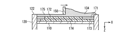
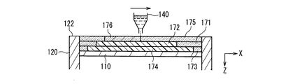
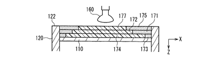
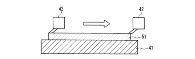
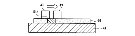
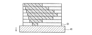
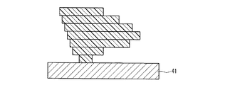
図20は、上記の積層造形装置によって、造形物が形成される工程を示す図である。まず、図20Aに示すように、積層造形装置が備える造形テーブル41上に粉体フィーダ42によって粉体が均一に散布され、粉体層51が形成される。次いで、図20Bに示すように、インクジェットヘッド43が、粉体層51のうち造形したい部分51aに液剤を射出する。液剤が射出された部分51aは、例えば、光が照射されることによって形状化する。図20Aおよび20Bに示す動作は、造形テーブル41が所定のピッチだけ降下するたびに繰り返される。その結果、図20Cに示すように、層の一部が選択的に形状化された粉体層が複数積層される。最後に形状化していない粉体を除去することにより、形状化した部分だけが造形物として残る(図20D参照)。このように積層造形装置を用いることによって、例えば、歯科用構造材のような複雑な形状の構造材を形成することができる。
FIG. 20 is a diagram illustrating a process in which a model is formed by the additive manufacturing apparatus. First, as shown in FIG. 20A, powder is uniformly dispersed by a
その後この造形物を焼結した後に仕上げ処理を施して目的の構造物を完成する。
しかしながら、上記の積層造形装置によって形成される造形物を補綴物のフレームなどに応用する場合、造形後の焼成工程が必要になるので、昇温中に造形物が自重や炉内の雰囲気の流れなどによって垂れたり、崩れたりして本来の目的の形状とは異なる形に変形する事が多かった。特にロングスパンブリッジフレームなどの長大な造形物を焼成する場合には修正しきれないほどの大きな変形を生じることも多い。また、焼成が不要な材料で造形物が形成される場合であっても、形状化する際の乾燥や重合により、変形を生じることがある。 However, when applying a model formed by the layered modeling apparatus to a prosthesis frame or the like, a firing process after modeling is required, so that the model has its own weight or the flow of the atmosphere in the furnace during the temperature rise. In many cases, it droops or collapses due to the above, and deforms into a shape different from the original shape. In particular, when firing a long shaped object such as a long span bridge frame, a large deformation that cannot be corrected often occurs. Further, even when a shaped article is formed of a material that does not require firing, deformation may occur due to drying or polymerization during shaping.
また、歯科補綴物のフレームなどは、患者の支台歯にセメントなどの材料を介して適合、合着するように設計されることが多いため、造形テーブルとの間に空間を有する場合が多い。そのため、事前に把握する事が困難な変形が生じやすい。 In addition, since a dental prosthesis frame or the like is often designed to fit and attach to a patient's abutment tooth via a material such as cement, there is often a space between the shaping table and the table. . For this reason, deformation that is difficult to grasp in advance is likely to occur.
そこで、本発明は、形成過程または焼成過程で変形しにくい構造の造形物を表す造形データを作成する造形データ作成システム、プログラムおよび前記造形物の製造方法を提供することを目的とする。 Then, an object of this invention is to provide the modeling data creation system and program which create the modeling data showing the modeling object of a structure which cannot change easily in a formation process or a baking process, and the manufacturing method of the said modeling object.
本発明にかかる造形データ作成システムは、層光を照射することにより、またはバインダー液を含浸させることにより、少なくとも一部を形状化させた造形層を、基礎平面上に積層することによって前記形状化された部分を造形物として形成する積層造形装置で用いられる、前記造形物の形状を表す造形データを作成する造形データ作成システムであって、所望の構造物の形状を表す構造物データを入力する構造物データ入力部と、前記積層造形装置が形成する前記造形物に用いられる材料の組成を表す組成データを記録する組成データ記録部と、前記造形物に用いられる可能性のある材料の組成と、当該材料の乾燥、重合または焼結による変化の量を示す変化量データとを対応づけて記録する変化量データ記録部と、前記組成データで示される材料の組成に対応する変化の量を示す変化量データを前記変化量データから取得し、取得した変化量データに基づいて、前記構造物データを用いて形成される造形物が、乾燥、重合または焼結による変化後に前記所望の構造物の形状に近くなるように当該構造物データを補正する補正部と、前記構造物を前記基礎平面上に配置し、前記配置された前記構造物を前記基礎平面に垂直に投影した投影面と、前記構造物との間の空間の外形を表す外形データを、前記構造物データを用いて生成する外形生成部と、前記空間の略全体を満たすように形成され、前記構造物を支持する支持部材の形状を表す支持部材データを生成する支持部材生成部と、前記基礎平面に略平行な複数の平面それぞれにおける断面形状を表す断面データを、前記構造物データ、前記支持部材データおよび前記外形データに基づいて生成する断面生成部とを備える。 The modeling data creation system according to the present invention is formed by laminating a modeling layer formed at least partially on a basic plane by irradiating layer light or impregnating with a binder liquid. A modeling data creation system for creating modeling data representing the shape of the modeled object, which is used in a layered modeling apparatus that forms the formed part as a modeled object, and inputs structure data representing the shape of a desired structure A structure data input unit; a composition data recording unit that records composition data representing a composition of a material used for the modeled object formed by the additive manufacturing apparatus; and a composition of a material that may be used for the modeled object. A change amount data recording unit for recording change amount data indicating the amount of change due to drying, polymerization or sintering of the material in association with each other, and the composition data Change amount data indicating the amount of change corresponding to the composition of the material to be obtained is acquired from the change amount data, and based on the acquired change amount data, the shaped object formed using the structure data is dried and polymerized. Alternatively, a correction unit that corrects the structure data so as to be close to the shape of the desired structure after change due to sintering, and the structure is arranged on the base plane, and the arranged structure is An outline generation unit that generates outline data representing the outline of the space between the projection plane projected perpendicularly to the base plane and the structure using the structure data, and so as to satisfy substantially the entire space. A support member generating unit that generates support member data that represents the shape of the support member that is formed and supports the structure, and cross-sectional data that represents the cross-sectional shape in each of a plurality of planes substantially parallel to the base plane. Chromatography comprising data and a section generating unit that generates, based on the support member data and the outline data.
前記補正部は、造形物の乾燥、重合または焼結による変化の量を示す変化量データを用いることにより、予め想定される乾燥、重合または焼結による収縮や変形など変化の量に応じて、構造物データを補正することができる。そのため、積層造形装置が構造物データを基に形成する造形物が、できるだけ所望の形状に近くなるように、構造物データが補正される。これにより、造形物が乾燥、重合または焼結(焼成)後に目的の形状および大きさとなることを可能にする構造物データが得られる。 According to the amount of change such as shrinkage or deformation due to drying, polymerization or sintering, which is assumed in advance, by using the change amount data indicating the amount of change due to drying, polymerization or sintering of the shaped object, The structure data can be corrected. Therefore, the structure data is corrected so that the modeled object formed by the additive manufacturing apparatus based on the structure data is as close to the desired shape as possible. As a result, structure data that enables the shaped object to have the desired shape and size after drying, polymerization, or sintering (firing) is obtained.
さらに、前記支持部材生成部は、前記外形データで表される空間の略全体を満たす支持部材の形状を表す支持部材データを生成する。そのため、前記支持部材データで表される前記支持部材と、前記構造物データで表される前記構造物とで構成される造形物は、前記構造物の前記基礎平面側の面すなわち、前記構造物の下面が前記支持部材によって前記基礎平面上に略全面に渡って支持される構成となる。 Further, the support member generation unit generates support member data representing the shape of the support member that satisfies substantially the entire space represented by the outer shape data. Therefore, the modeled object composed of the support member represented by the support member data and the structure represented by the structure data is a surface on the base plane side of the structure, that is, the structure. The lower surface is supported on the base plane over the entire surface by the support member.
このような補正された構造物データ、支持部材データおよび外形データにより造形物の断面形状を表す断面データが生成される。上述のように補正部は、前記積層造形装置がこの断面データを用いて、造形物の形成過程や、焼成工程で生じる変化の量を見越した構造物データの補正を行っている。その結果、前記断面データを用いて積層され、焼結された後の造形物は、構造物データ入力部で入力された構造物データが示す所望の構造物の形状を正確に反映した形状となる。すなわち、構造物データで表される構造物を形成する過程または焼結する過程で、前記構造物が収縮する等して変化することによる適合性や精度の低下が抑えられる。 Cross-sectional data representing the cross-sectional shape of the modeled object is generated from such corrected structure data, support member data, and outer shape data. As described above, the correction unit uses the cross-sectional data to correct the structure data in anticipation of the amount of change that occurs in the formation process of the molded object and the firing process. As a result, the shaped object after being laminated and sintered using the cross-sectional data has a shape that accurately reflects the shape of the desired structure indicated by the structure data input in the structure data input unit. . That is, in the process of forming the structure represented by the structure data or in the process of sintering, a decrease in compatibility and accuracy due to the structure changing due to shrinkage or the like can be suppressed.
さらに、前記断面データを用いて積層される構造物は、前記支持部材によって、その下面が前記基礎平面上に、略全面に渡って支持される状態で形成される。そのため、前記断面データに基づいた造形物が形成される過程においては、構造物の反り等の変形が抑えられる。さらに、形成過程において、支持部材によって構造物の下面が全面的に支持されているので、構造物は目的の形状を保ったまま正確に形成される。 Furthermore, the structure laminated using the cross-sectional data is formed in a state where the lower surface of the structure is supported on the basic plane by the support member over substantially the entire surface. Therefore, deformation such as warping of the structure can be suppressed in the process of forming the shaped object based on the cross-sectional data. Furthermore, since the lower surface of the structure is fully supported by the support member in the formation process, the structure is accurately formed while maintaining the target shape.
したがって、造形データ作成システムは、形成過程で変形しにくく、かつ形成、焼結後に所望の形状を正確に反映した造形物を得るための造形データを提供することができる。造形データ作成システムは、例えば、クラウン、ブリッジ等のように、その表面が複雑で、かつ精密に形成する必要がある構造物の造形に有用な造形データを提供することができる。 Therefore, the modeling data creation system can provide modeling data for obtaining a model that is not easily deformed in the forming process and accurately reflects a desired shape after forming and sintering. The modeling data creation system can provide modeling data useful for modeling a structure whose surface is complex and needs to be precisely formed, such as a crown and a bridge.
本発明によれば、本発明は、形成過程または焼結過程で変形しにくい構造の造形物を表す造形データを作成する造形データ作成システム、プログラムおよび前記造形物の製造方法を提供することができる。 According to the present invention, the present invention can provide a modeling data creation system, a program, and a method for manufacturing the modeled object that create modeled data representing a modeled object that is difficult to deform in the forming process or the sintering process. .
本発明の実施形態において、前記構造物データ入力部は、前記所望の構造物が他の物体に装着されるものである場合に、前記物体と前記構造物との相対的な位置関係を示す関係データをさらに入力し、前記関係データに基づいて、前記物体と前記構造物との前記位置関係を固定するための部材を表す補助形状データを生成し、前記構造物データに付加する補助形状データ生成部をさらに備える態様とすることができる。 In an embodiment of the present invention, the structure data input unit indicates a relative positional relationship between the object and the structure when the desired structure is attached to another object. Further inputting data, generating auxiliary shape data representing a member for fixing the positional relationship between the object and the structure based on the relationship data, and generating auxiliary shape data to be added to the structure data It can be set as the aspect further provided with a part.
補助形状データ生成部により、構造物と装着対象の物体との位置関係を固定するための部材を表す情報が付加された構造物データが生成される。この構造物データから生成される断面データが積層造形装置で用いられることにより、前記部材が付加された構造物が形成される。すなわち、物体に装着する際にその向きや位置を一意に決定して正確に適合させる事ができる構造物を表す構造物データが得られる。その結果、構造物を、前記物体に対して正しい位置および向きで装着することが可能になる。構造物を物体へ装着した時の向きのずれ等が生じることが抑えられる。 The auxiliary shape data generation unit generates structure data to which information representing a member for fixing the positional relationship between the structure and the object to be mounted is added. The cross-section data generated from the structure data is used in the additive manufacturing apparatus, whereby the structure to which the member is added is formed. That is, structure data representing a structure that can be accurately matched by uniquely determining its orientation and position when mounted on an object is obtained. As a result, the structure can be attached to the object at the correct position and orientation. It is possible to suppress the deviation of the orientation when the structure is mounted on the object.
例えば、造形しようとする構造物がクラウンやブリッジなどのフレームとして使用される場合、補助形状データ生成部により、支台歯との合着または接着のためのセメントスペースを付加したり、フレームが支台歯に対して正しい位置及び向きを維持するように、フレームの位置決めをしたりすることが可能になる。 For example, when a structure to be shaped is used as a frame such as a crown or bridge, the auxiliary shape data generation unit adds a cement space for attachment or adhesion to the abutment tooth, or supports the frame. The frame can be positioned so as to maintain the correct position and orientation with respect to the base tooth.
本発明の実施形態において、前記補助形状データ生成部は、前記前記物体と前記構造物との間に設けられた板状体または柱状体を表すデータを、補助形状データとして生成するものであって、前記組成データ記録部に記録された前記組成データを用いて、前記板状体または前記柱状体の断面積を求めることで前記補助形状データを生成することができる。 In an embodiment of the present invention, the auxiliary shape data generation unit generates data representing a plate-like body or a columnar body provided between the object and the structure as auxiliary shape data. The auxiliary shape data can be generated by obtaining a cross-sectional area of the plate-like body or the columnar body using the composition data recorded in the composition data recording section.
前記補助形状データで表される部材は、複数の板状体または柱状体になっているので、前記断面データで表される構造物と物体との間は、前記部材によって複数箇所で支持され、かつ、前記構造物と部材が接する面積が小さくなる。これにより、精密な形状の構造物を物体に正確に位置決めすることが容易になる。 Since the member represented by the auxiliary shape data is a plurality of plate-like bodies or columnar bodies, the structure and the object represented by the cross-sectional data are supported at a plurality of locations by the member, And the area which the said structure and a member contact becomes small. Thereby, it becomes easy to accurately position a precisely-shaped structure on the object.
本発明の実施形態において、前記補助形状データ生成部は、前記部材が前記物体と接触する部分の面積を、前記位置関係を固定するのに必要な面積であり、且つ前記構造物と前記物体との間の接着強度が所定値を下回らないために必要な面積となるように構造物データおよび関係データを用いて計算し、前記補助形状データを生成することができる。 In an embodiment of the present invention, the auxiliary shape data generation unit has an area of a portion where the member contacts the object, an area necessary for fixing the positional relationship, and the structure and the object. The auxiliary shape data can be generated by calculating using the structure data and the relational data so that the area required to prevent the adhesive strength between the two pieces from falling below a predetermined value.
これにより、構造物と物体との相対位置を十分な強度で固定し、かつ、構造物と物体を十分な強度で接着することを可能にする補助形状データが得られる。 Thereby, auxiliary shape data that makes it possible to fix the relative position between the structure and the object with sufficient strength and to bond the structure and the object with sufficient strength is obtained.
本発明の実施形態において、前記補助形状データ生成部は、前記構造物データが示す構造体のうち、前記物体に装着される面に付加され、前記構造体と前記物体との間に所望のスペースに等しい厚みを持ち、前記物体と接触する面が前記物体の該当する部分の形状と同じ形状の面である複数の板状体、または柱状体で形成される部材を表す補助形状データを生成することができる。 In an embodiment of the present invention, the auxiliary shape data generation unit is added to a surface attached to the object among the structures indicated by the structure data, and a desired space between the structure and the object. Auxiliary shape data representing a member formed of a plurality of plate-like bodies or columnar bodies having a thickness equal to and a surface in contact with the object having the same shape as the corresponding portion of the object is generated. be able to.
これにより、完成した造形物は装着対象の物体に正しい位置と向きで、接着等のための適切な厚みを保って、より的確に装着固定されることが可能になる。例えば、完成した造形物が、患者の口腔内の支台歯に装着される補綴物である場合、その補綴物は、支台歯に対して正しい位置と向きで、適切なセメント層の厚みを保って的確に装着固定されることが可能になる。 As a result, the completed modeled object can be mounted and fixed more accurately with the correct position and orientation on the object to be mounted while maintaining an appropriate thickness for adhesion and the like. For example, if the completed object is a prosthesis that is attached to an abutment tooth in the patient's mouth, the prosthesis is positioned and oriented with respect to the abutment tooth and has an appropriate cement layer thickness. It is possible to maintain and accurately fix it.
本発明の実施形態において、前記補助形状データ生成部は、前記構造体の前記部材と当接する部分における法線方向に伸びている複数の板状体、または柱状体で形成される部材を表す補助形状データを生成することができる。これにより、補助形状データ生成部は、簡単な計算により補助形状データを生成することができる。 In an embodiment of the present invention, the auxiliary shape data generation unit is an auxiliary representing a member formed of a plurality of plate-like bodies or columnar bodies extending in a normal direction in a portion of the structure that contacts the member. Shape data can be generated. Thereby, the auxiliary shape data generation unit can generate auxiliary shape data by a simple calculation.
本発明の実施形態において、前記外形生成部は、前記補正部によって補正された補正済み構造物データと前記基礎平面上との間にできる空間の体積に基づいて前記補正済み構造物の配置を決定し、前記補正済み構造物データと前記基礎平面との間にできる空間の外形を表す外形データを生成することができる。 In an embodiment of the present invention, the outline generation unit determines an arrangement of the corrected structure based on a volume of a space formed between the corrected structure data corrected by the correction unit and the base plane. Then, it is possible to generate outer shape data representing the outer shape of the space formed between the corrected structure data and the base plane.
これにより、前記外形生成部が、前記空間の体積が最適になるように前記構造物を配置することができる。そのため、前記外形データは、最適な体積を持つ空間の外形を表すことになる。このような最適な体積を持つ空間の外形データに基づいて、前記支持部材生成部が支持部材データを生成する。そのため、最適な体積を持つ支持部材を表す支持部材データが得られる。例えば、前記空間の体積が小さくなると、前記空間に形成される支持部材も小さくてすむ。すなわち、前記支持部材データで表される前記支持部材が小さくなる。その結果、前記支持部材の形成に用いられる材料の量が少なくてすむ。 Thereby, the said external shape production | generation part can arrange | position the said structure so that the volume of the said space may become optimal. Therefore, the outline data represents the outline of a space having an optimal volume. Based on the outer shape data of the space having such an optimal volume, the support member generation unit generates support member data. Therefore, support member data representing a support member having an optimal volume is obtained. For example, when the volume of the space is reduced, the support member formed in the space can be reduced. That is, the support member represented by the support member data becomes smaller. As a result, the amount of material used to form the support member can be reduced.
本発明の実施形態において、前記支持部材データは、前記基礎平面に対して垂直に設けられた複数の板状体または柱状体で形成される支持部材を表すことができる。 In an embodiment of the present invention, the support member data may represent a support member formed of a plurality of plate-like bodies or columnar bodies provided perpendicular to the base plane.
前記支持部材データで表される支持部材は、複数の板状体または柱状体になっているので、前記支持部材が前記構造物に接する部分が小さくなる。従って、前記断面データで表される構造物は、前記支持部材によって全体に渡って支持され、かつ、前記支持部材と接する面積が小さくなる。このような断面データに基づいて形成される構造物は、形成過程での変形が抑えられ、かつ、支持部材を取り外しても、その残骸が構造物に残りにくいものとなる。すなわち、前記支持部材と前記構造物とが接する面積が小さいと、前記支持部材を除去する際に、前記構造物の根元近くで折れやすくなる。その結果、前記支持部材を除去した後の前記構造物の表面を平滑化するための後加工が容易になる。つまり、精密な形状の構造物を得ることが容易になる。このように、前記造形データ作成システムは、上記の支持部材データが用いることにより、精密な構造物を容易に得るための造形データを提供することが可能となる。 Since the support member represented by the support member data is a plurality of plate-like bodies or columnar bodies, a portion where the support member is in contact with the structure is reduced. Therefore, the structure represented by the cross-sectional data is supported throughout the support member, and the area in contact with the support member is reduced. A structure formed based on such cross-sectional data is prevented from being deformed during the formation process, and even if the support member is removed, the debris is unlikely to remain in the structure. That is, when the area where the support member and the structure are in contact with each other is small, the support member is easily broken near the base of the structure when the support member is removed. As a result, post-processing for smoothing the surface of the structure after removing the support member is facilitated. That is, it becomes easy to obtain a precisely shaped structure. As described above, the modeling data creation system can provide modeling data for easily obtaining a precise structure by using the support member data.
本発明の実施形態において、前記支持部材データは、前記板状体または前記柱状体の水平方向の厚みが、前記構造物に接する部分において、他の部分に比べて小さくなっている前記支持部材を表す態様とすることができる。 In an embodiment of the present invention, the support member data includes the support member in which a horizontal thickness of the plate-like body or the columnar body is smaller than that of other portions in a portion in contact with the structure. It can be set as the aspect to represent.
これにより、前記支持部材データで表される前記支持部材が前記構造物に接する部分の面積が小さくなる。すなわち、前記支持部材と前記構造物との接点が小さくなるので、前記断面データに基づいて造形される造形物においては、前記支持部材は、前記構造物から除去される際に、前記構造物に接する部分の近くで折れやすくなる。その結果、前記構造物には、前記支持部材の残骸が残りにくくなる。すなわち、前記支持部材データを用いて生成される断面データは、前記支持部材の残骸が残りにくい形状の造形物を表すことになる。 Thereby, the area of the part which the said supporting member represented with the said supporting member data contacts the said structure becomes small. In other words, since the contact point between the support member and the structure is reduced, in the modeled object that is modeled based on the cross-sectional data, the support member is attached to the structure when the support member is removed from the structure. It becomes easy to break near the part that touches. As a result, it is difficult for the debris of the support member to remain in the structure. In other words, the cross-sectional data generated using the support member data represents a shaped object having a shape in which the debris of the support member is unlikely to remain.
本発明の実施形態において、前記支持部材生成部は、前記構造物に接する部分の近くに切り欠きを有する支持部材を表す支持部材データを生成することができる。これにより、前記構造物から前記支持部材を除去した際に、前記構造物に残骸が残りにくい形状を表す支持部材データが得られる。 In an embodiment of the present invention, the support member generation unit can generate support member data representing a support member having a notch near a portion in contact with the structure. Thereby, when the support member is removed from the structure, support member data representing a shape in which debris hardly remains in the structure is obtained.
本発明の実施形態において、前記支持部材生成部は、前記構造物において、前記支持部材が接する部分の周辺部を構造物の内面方向へ窪ませるように前記構造物データを修正することができる。これにより、前記構造物から前記支持部材を除去した際に、前記構造物に残骸が残りにくい形状を表す構造物データが得られる。 In an embodiment of the present invention, the support member generation unit can correct the structure data so that a peripheral portion of a portion in contact with the support member in the structure is recessed toward the inner surface of the structure. Thereby, when the support member is removed from the structure, structure data representing a shape in which debris hardly remains in the structure is obtained.
本発明の実施形態において、前記組成データ記録部は、前記支持部材に用いられる材料の組成を表す組成データもさらに記録し、前記支持部材生成部は、前記組成データ記録部に記録された前記組成データを用いて、前記板状体または前記柱状体の水平方向の厚みを求めることができる。 In an embodiment of the present invention, the composition data recording unit further records composition data representing a composition of a material used for the support member, and the support member generating unit records the composition recorded in the composition data recording unit. Using the data, the horizontal thickness of the plate-like body or the columnar body can be obtained.
前記支持部材生成部は、前記組成データを用いることで、支持部材に必要な強度を確保し、かつ最小の厚みが得られる。すなわち、前記支持部材生成部は、前記支持部材が適切な強度を持ち、かつ前記構造物から容易に取り外すことができ、かつ取り除いた後の構造物の表面に前記支持部材の一部が残らない程度の前記板状体または前記柱状体の水平方向の厚みを求めることができる。 By using the composition data, the support member generation unit ensures the strength necessary for the support member and obtains the minimum thickness. In other words, the support member generating unit has an appropriate strength and can be easily detached from the structure, and a part of the support member does not remain on the surface of the structure after the removal. The thickness in the horizontal direction of the plate-like body or the columnar body can be determined.
本発明の実施形態において、前記支持部材生成部は、前記構造物が前記支持部材に与える力の分布を、構造物データを用いて計算し、該分布に基づいて前記板状体または前記柱状体の水平方向の厚みを求めることができる。 In an embodiment of the present invention, the support member generation unit calculates a distribution of force that the structure gives to the support member using structure data, and the plate-like body or the columnar body based on the distribution. The horizontal thickness can be obtained.
前記支持部材生成部は、前記構造物から前記支持部材に加わる力の分布に基づいて、前記板状体または前記柱状体の水平方向の厚みを求めるので、前記支持部材が前記構造物の変形を抑えるのに必要な強度を持ち、かつ前記構造物から容易に取り外すことができ、かつ取り除いた後の構造物の表面に前記支持部材の一部が残らない程度の前記厚みを求めることができる。なお、前記支持部材生成部は、前記組成データおよび前記力の分布の両方を用いて前記厚みを求めてもよい。 The support member generation unit obtains a horizontal thickness of the plate-like body or the columnar body based on a distribution of force applied from the structure to the support member, so that the support member deforms the structure. The thickness can be obtained such that it has a strength necessary to suppress, can be easily detached from the structure, and does not leave a part of the support member on the surface of the structure after removal. The support member generation unit may obtain the thickness using both the composition data and the force distribution.
本発明の実施形態において、前記構造物は、口腔内の補綴物であり、前記構造物データは、前記口腔内またはその周辺部を測定することによって得られた測定データを基に生成されたデータである態様とすることができる。 In an embodiment of the present invention, the structure is a prosthesis in the oral cavity, and the structure data is data generated based on measurement data obtained by measuring the oral cavity or its peripheral part. It can be set as the aspect which is.
口腔内の補綴物の形状を表す構造物データは、前記測定によって得られた測定データを基に生成され、乾燥、重合または焼結による収縮量を予め見越して補正をかけられているので、焼結後に前記口腔内またはその周辺部の形状に適合した形状の補綴物を表すデータとなる。 The structure data representing the shape of the prosthesis in the oral cavity is generated on the basis of the measurement data obtained by the above measurement and is corrected in advance by taking into account the shrinkage due to drying, polymerization or sintering. The data represents a prosthesis having a shape suitable for the shape of the oral cavity or its peripheral portion after ligation.
前記造形データ作成システムで作成される前記断面データと、前記積層造形装置とを用いて前記構造物を製造するための製造方法も本発明の一実施形態である。この製造方法は、前記積層造形装置が備える上下に移動可能な造形テーブル上に、所定の厚みの造形層を形成する層形成工程と、前記造形層の少なくとも一部であって、前記断面データが表す断面形状に応じた形状の部分のみ選択的に光を照射するかまたはバインダー液を射出し、含浸させて形状化する造形工程と、前記造形テーブルを前記所定の厚み分降下させる降下工程と、前記層形成工程および前記形状化工程を、前記断面データが表す前記複数の平面それぞれについて順次繰り返すことによって、前記造形層を積層する積層工程と、前記積層工程で積層された前記造形層において、前記形状化工程で形状化された部分以外の部分を除去することによって、前記支持部材によって前記造形テーブル上に支持された状態の前記構造物を形成する除去工程とを備える。 A manufacturing method for manufacturing the structure using the cross-sectional data created by the modeling data creation system and the layered modeling apparatus is also an embodiment of the present invention. The manufacturing method includes a layer forming step of forming a modeling layer having a predetermined thickness on a modeling table that is movable up and down included in the layered modeling apparatus, and at least a part of the modeling layer, wherein the cross-sectional data is A modeling step of selectively irradiating only a portion of the shape corresponding to the cross-sectional shape to be represented or injecting a binder liquid and impregnating and shaping, a descending step of lowering the modeling table by the predetermined thickness, In the layering step of laminating the modeling layer by sequentially repeating the layer forming step and the shaping step for each of the plurality of planes represented by the cross-sectional data, and in the modeling layer stacked in the layering step, By removing a portion other than the portion shaped in the shaping step, the structure in a state of being supported on the modeling table by the support member is shaped. And a removing step for.
上記の製造方法によれば、前記積層造形装置は、前記断面データに基づいて前記層形成工程、前記形状化工程および前記降下工程を繰り返すことにより、前記形状化工程で形状化された部分が、前記支持部材によって前記造形テーブル上に支持される前記構造物となる。そのため、前記構造物を形成する過程において前記構造物に生じる変形を抑えることができる。前記除去工程により、前記造形層のうち、前記構造物と同時に形成された支持形状部分が除去される。 According to the above manufacturing method, the layered manufacturing apparatus repeats the layer forming step, the shaping step, and the descending step based on the cross-sectional data, so that the portion shaped in the shaping step is The structure is supported on the modeling table by the support member. Therefore, deformation that occurs in the structure during the process of forming the structure can be suppressed. By the removal step, a support shape portion formed simultaneously with the structure is removed from the modeling layer.
また、前記積層造形装置によって形成された前記構造物は、焼結によって生じる収縮、変形などの変化を予め補正したデータを基にしているので焼結後に目的の大きさとなり、良好な適合性を持つことができる。 In addition, the structure formed by the additive manufacturing apparatus is based on data obtained by correcting changes such as shrinkage and deformation caused by sintering in advance. Can have.
光を照射することにより、またはバインダー液を含浸させることにより、少なくとも一部を形状化させた造形層を、基礎平面上に積層することによって前記形状化された部分を造形物として形成する積層造形装置で用いられる、前記造形物の形状を表す造形データを作成する処理をコンピュータに実行させる造形データ作成プログラムも本発明の一実施形態である。所望の構造物の形状を表す構造物データを入力する構造物データ入力処理と、前記積層造形装置が形成する前記造形物に用いられる材料の組成を表す組成データを記録する組成データ記録部と、前記造形物に用いられる可能性のある材料の組成と、当該材料の乾燥、重合または焼結による変化の量を示す変化量データとを対応づけて記録する変化量データ記録部とにアクセスし、前記組成データで示される材料の組成に対応する変化の量を示す変化量データを前記変化量データから取得し、取得した変化量データに基づいて、前記構造物データを用いて形成される造形物が、乾燥、重合または焼結による変化後に前記所望の構造物の形状に近くなるように当該構造物データを補正する補正処理と、前記構造物を前記基礎平面上に配置し、前記配置された前記構造物を前記基礎平面に垂直に投影した投影面と、前記構造物との間の空間の外形を表す外形データを、前記構造物データを用いて生成する外形生成処理と、前記空間の略全体を満たすように形成され、前記構造物を支持する支持部材の形状を表す支持部材データを生成する支持部材生成処理と、前記支持部材データで表される前記支持部材と、前記補正部によって補正された構造物データで表される前記構造物とで構成される造形物の、前記基礎平面に略平行な複数の平面それぞれにおける断面形状を表す断面データを、前記構造物データ、前記支持部材データおよび前記外形データに基づいて生成する断面生成処理とをコンピュータに実行させる。 Laminate modeling that forms the shaped part as a modeled object by laminating a shaping layer at least partially shaped by irradiating light or impregnating with a binder liquid on a basic plane. A modeling data creation program for causing a computer to execute processing for creating modeling data representing the shape of the modeled object used in the apparatus is also an embodiment of the present invention. A structure data input unit that inputs structure data representing the shape of a desired structure; a composition data recording unit that records composition data representing a composition of a material used for the shaped article formed by the layered shaping apparatus; Access to a change amount data recording unit that records the composition of a material that can be used for the modeled object and change amount data indicating the amount of change due to drying, polymerization, or sintering of the material in association with each other, A change amount data indicating an amount of change corresponding to the composition of the material indicated by the composition data is acquired from the change amount data, and a shaped article formed using the structure data based on the acquired change amount data Correction processing for correcting the structure data so as to be close to the shape of the desired structure after change due to drying, polymerization or sintering, and arranging the structure on the base plane, An outer shape generation process for generating outer shape data representing the outer shape of a space between the projection surface obtained by projecting the placed structure perpendicular to the base plane and the structure using the structure data; A support member generation process for generating support member data representing the shape of a support member that supports the structure, and is formed so as to fill substantially the entire space; the support member represented by the support member data; and the correction Cross-sectional data representing a cross-sectional shape in each of a plurality of planes substantially parallel to the basic plane of a model formed by the structure represented by the structure data corrected by the unit, the structure data, The computer executes a cross-section generation process that is generated based on the support member data and the outer shape data.
上記プログラムにより、前記積層造形装置が、前記基礎平面上に前記構造物を支持するための前記支持部材を作成するために用いられる支持部材データが生成される。さらに、前記積層造形装置で利用しやすい断面データを生成することができる。 According to the program, support member data used for the additive manufacturing apparatus to create the support member for supporting the structure on the base plane is generated. Furthermore, it is possible to generate cross-sectional data that can be easily used by the additive manufacturing apparatus.
本発明の実施形態にかかる製造方法は、その層の一部を選択的に形状化させた造形層を基礎平面上に積層することによって、前記形状化された部分を造形物として形成する造形物の製造方法であって、所望の形状を有する構造物を前記基礎平面上で支持するための支持部材を形成する工程と、前記支持部材の上に前記構造物を形成する工程とを備える。 In the manufacturing method according to the embodiment of the present invention, a modeled object is formed by stacking a modeled layer in which a part of the layer is selectively shaped on a basic plane, thereby forming the shaped part as a modeled object. The method includes: a step of forming a support member for supporting a structure having a desired shape on the base plane, and a step of forming the structure on the support member.
以下、本発明の実施形態について、図面を用いて詳しく説明する。 Hereinafter, embodiments of the present invention will be described in detail with reference to the drawings.
(実施の形態1)
実施の形態1は、造形テーブル上に粉体を積層させることよって形成される造形物の形状を表すデータを作成する造形データ作成システムに関する。本実施形態においては、造形物が、例えば、陶材焼付け冠のブリッジフレームとして用いるジルコニア製構造物を積層造形装置で製造する場合を例にとり説明する。図1は、本実施の形態1における造形データ作成システムの構成を表す機能ブロック図である。(Embodiment 1)
The first embodiment relates to a modeling data creation system that creates data representing the shape of a modeled object formed by laminating powder on a modeling table. In the present embodiment, a case where the modeled object is a zirconia structure used as, for example, a bridge frame of a porcelain baking crown will be described as an example. FIG. 1 is a functional block diagram showing the configuration of the modeling data creation system in the first embodiment.
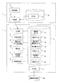
図1に示すように、造形データ作成システム1は、入力部3、出力部4、補助形状データ生成部27、補正部28、外形生成部5、支持部材生成部7、断面生成部9および記録部11を備える。造形データ作成システム1は、補綴物形状データ作成システム2および積層造形装置100に接続されている。
As shown in FIG. 1, the modeling
補綴物形状データ作成システム2は、測定装置17、作成部15、モデル記録部13を備える。測定装置17は、例えば、患者の口腔内またはその周辺部の形状等を測定する。測定装置17が測定した形状は、測定データとして、作成部15に送られる。作成部15は、測定装置17から送られる測定データと、モデル記録部13に予め記録されたモデル21とに基づいて、所望の補綴物の形状を表す構造物データ22を作成する。モデル21には、例えば、補綴物の基本的または一般的な構造を表すデータ等が含まれる。
The prosthesis shape
入力部3は、作成部15が作成した構造物データを読み込み、記録部11に記録する。その結果、造形データ作成システム1が構造物データ22を利用できる状態になる。また、入力部3は、構造物データで示される構造物が、他の物体に装着されるものである場合には、その装着時における物体と構造物との位置関係を示す関係データを入力する。関係データには、例えば、構造物が物体に装着される際に、物体に接着される構造物上の面を特定するデータや、物体と構造物との間に設けられる空間の厚みを示すデータ、装着対象の物体の形状を表すデータ等が含まれる。
The
補助形状データ生成部27は、記録部11に記録された構造物データ22と関係データに基づいて補助形状データを生成し、これを構造物データに付加して新たな構造物データ22として記録部11に記録する。補助形状データは、構造物データ22で表される構造物が物体に装着される際の、構造物と物体との位置関係を固定する補助部材の形状(以下、補助形状と称する)を表すデータである。
The auxiliary shape
例えば、構造物が陶材焼付けブリッジフレーム(以下、単にフレームと称する)である場合、フレームが患者の口腔内の支台歯に装着される際に、フレームを、支台歯に対して正しい位置と正しい向きで、且つ支台歯とフレームとの間に適切なスペースを維持して装着するための補助部材の形状を表す補助形状データが生成される。 For example, when the structure is a porcelain baked bridge frame (hereinafter simply referred to as a frame), when the frame is attached to the abutment tooth in the patient's oral cavity, the frame is positioned in the correct position with respect to the abutment tooth. Auxiliary shape data representing the shape of the auxiliary member for mounting in the correct orientation and maintaining an appropriate space between the abutment tooth and the frame is generated.
補助形状データ生成部27が、補助形状を決定する際、あらかじめ記録部11に記録されている組成データ23が参照されることが好ましい。組成データ23は、例えば、補助部材、構造物または支持部材を形成する材料の組成を表すデータである。
When the auxiliary shape
なお、この補助形状データ生成部27は製造しようとする構造物の使用目的によって、補助形状が不必要である場合には経由させない事ができる。
The auxiliary shape
補正部28は、後の工程で造形した構造物を乾燥、重合、焼結、焼成する際に生じる変形や収縮による精度や適合性の低下を抑制するため、記録部11に記録された構造物データ22、組成データ23および変化量データ30に基づいて、構造物データを補正した補正済み構造物データ29を生成する。生成された補正済み構造物データ29は記録部11に記録される。
The
外形生成部5は、記録部11に記録された補正済み構造物データ29に基づいて、外形データ24を生成する。外形データ24は、補正済み構造物データ29が表す構造物を、例えば、造形テーブル上等の基礎平面上に配置した場合の、構造物と造形テーブルとの間にできる空間の外形を表す外形データ24である。生成された外形データ24は記録部11に記録される。
The
支持部材生成部7は、記録部11に記録された外形データ24に基づいて、造形テーブル上で構造物を支持する支持部材の形状を表す支持部材データ25を生成する。支持部材データ25は、例えば、外形データ24で表される空間内に設けられる支持部材の形状を表すデータである。支持部材生成部7が、支持部材の形状を決定する際、あらかじめ記録部11に記録されている組成データ23が参照されることが好ましい。生成された支持部材データ25は記録部11に記録される。
The support
断面生成部9は、補正済み構造物データ29と支持部材データ25とに基づいて、断面データ26を生成する。生成された断面データ26は、記録部11に記録される。
The cross section generator 9 generates
出力部4は、断面データ26を積層造形装置100へ出力する。また、出力部4は、積層造形装置100の動作を制御するための制御プログラムも積層造形装置100へ出力する。制御プログラムの例については、実施の形態2において後述する。積層造形装置100は、断面データ26および制御プログラムに基づいて、支持部材と構造物とで構成される造形物を作製する。積層造形装置100の構成および動作の詳細は後述する。
The output unit 4 outputs the
造形データ作成システム1および補綴物形状データ作成システム2は、例えば、パーソナルコンピュータ、サーバ等のコンピュータ上に構築される。造形データ作成システム1および補綴物形状データ作成システム2は、1台のコンピュータ上に構築されてもよいし、互いに異なる2台のコンピュータ上にそれぞれ構築されてもよい。入力部3、出力部4、外形生成部5、支持部材生成部7、断面生成部9、作成部15の機能は、コンピュータのCPUが所定のプログラムを実行することによって実現される。記録部11、モデル記録部13には、例えば、コンピュータに内蔵されているハードディスク、RAM等の記憶媒体の他、フレキシブルディスク、メモリカード等の可搬型記憶媒体や、ネットワーク上にある記憶装置内の記憶媒体等を用いることができる。
The modeling
次に、造形データ作成システム1の動作について説明する。本実施形態では、患者が使用する陶材焼付け冠のブリッジフレームとして用いるジルコニア製構造物を積層造形装置で作製するための造形データを作成する処理を例にとって説明する。ここで、造形データは、積層造形装置で作製される造形物の形状を表すデータである。
Next, the operation of the modeling
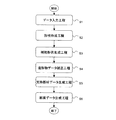
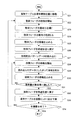
はじめに、大まかな処理の流れについて説明する。図2は、造形データ作成システム1が造形データを作成する際の処理の流れを示すフローチャートである。図2に示すように、まず、補綴物形状データ作成システム2の測定装置17が患者の口腔内またはその周辺を測定して測定データを得る。作成部15は、測定装置17から測定データを入力する(ステップS1)。
First, a rough processing flow will be described. FIG. 2 is a flowchart showing a process flow when the modeling
作成部15は、モデル記録部13に記録されたモデル21および測定データに基づいて、目的とする構造物、すなわちフレームの形状を表す構造物データ22を作成する。また、作成部15は、フレームを支台歯に装着する際の支台歯との位置関係を特定する関係データも作成する。(ステップS2)。作成部15が作成した構造物データおよび関係データは、入力部3により造形データ作成システム1に読み込まれ、記録部11に記録される。
The
補助形状データ生成部27は、作成部15が作成した構造物データ22および関係データを用いて、フレームとフレームを装着する支台歯との位置を固定するための補助部材の形状を表す補助形状データを作成し、これを構造物データ22に付加する。(ステップ3)。ここで、補助形状は、例えば、フレームを患者の支台歯に装着する際に術者が容易に正しい位置と正しい向きで装着できるようにするための位置決め用のガイド形状、及び/またはフレームを支台歯に装着する際に合着、あるいは接着のために用いられる歯科用セメントが介在するためのスペースを保持するためのスペーサ形状などである。
The auxiliary shape
なお、補助形状データ生成部27は、例えば、構造物が他の物体に装着するものでない場合のように、補助部材が必要ない場合には上記ステップ3の処理を実行しなくてもよい。
Note that the auxiliary shape
補正部28は、作成部15あるいは補助形状データ生成部27が作成した構造物データ22を補正した補正済み構造物データ29を作成する(ステップS4)。補正部28は、構造物データ22が示す構造物と、構造物データ22を用いて造形された構造物が焼結される際に生じる収縮や変形によって変化した構造物との差異が相殺されるように、構造物データ22を補正し、補正済み構造物データ29を作成する。
The
ステップ4において、補正部28は、記録部11に記録された組成データ23および変化量データ30を用いて、前記造形物の収縮量を参照あるいは算出し、これを用いて必要な補正を施して補正済み構造物データを生成する。
In step 4, the
外形生成部5と支持部材生成部7が、補正部28が作成した補正済み構造物データ29を用いて、構造物を支持する支持部材の形状を表す支持部材データ25を作成する(ステップS5)。
The outer
断面生成部9は、支持部材と補正済み構造物とで構成される造形物の、互いに平行な複数の平面それぞれにおける断面形状を表す断面データ26を生成する(ステップS6)。本実施形態においては、この断面データ26が、目的とする構造物であるフレームを作製するための造形データである。
The cross-section generator 9 generates
次に、一例としてブリッジのフレームを、所要の構造物とした場合の各ステップS1〜S6の詳細な処理について説明する。 Next, as an example, detailed processing in steps S1 to S6 when the bridge frame is a required structure will be described.
(ステップS1 データ入力工程)
ステップS1において、補綴物形状データ作成システム2の測定装置17が、例えば、ブリッジを使用する患者の口腔内および支台歯周辺部を測定することによって得た測定データを作成部15へ入力する。測定データは、例えば、支台歯形状、支台歯、対合歯列の形状、咬合高径(上下顎の間隔)、中心位(中心位置)、ゴシックアーチ等の患者固有の値である。ゴシックアーチは、顎の運動に伴って生じる特定部位の運動経路を描記したものである。患者の口腔内および支台歯周辺部の形状は、例えば、点群データ、すなわちXYZ座標値の集まりで表現される。(Step S1 data input process)
In step S <b> 1, the
(ステップS2 形状作成工程)
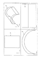
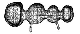
ステップS2の形状作成工程において、作成部15は、モデル記録部13に記録されたモデル21および測定データに基づいて、構造物データ22および関係データを作成する。図3Aは、作成部15が作成した構造物データ22が表すフレームの例を示す図である。なお、図3Aは、フレームが、後述するステップS5で生成される支持部材の上に形成された状態を示している。(Step S2 shape creation process)
In the shape creation step of step S2, the
作成部15は、測定データのうち、例えば、支台歯、隣接歯、対合歯(かみ合う相手の歯)の形状、反対側の歯牙形態、咬合高径(上下顎の間隔)、中心位(中心位置)、ゴシックアーチ等のデータから、製作しようとするフレームの大まかな形状を決定する。
In the measurement data, the
モデル記録部13に記録されたモデル21は、例えば、クラウン、ブリッジ等を再現するためのモデルである。モデル21には、例えば、各部位の歯牙ごとのクラウンや、さまざまな部位及び本数からなるブリッジ形状を作成する基になる各種フレーム形状のデータベースや、基本的または一般的なポンティックの形状を表すモデル等が含まれる。作成部15は、一般的なクラウン、ブリッジの形状を表すモデル21に、上記の測定データより得られた患者特有の値を反映させて、フレームの大まかな形状を表すフレームモデルを作成する。
The
作成部15は、例えば、組成データ23を参照してフレームの材質を特定し、特定したフレームの材質から必要な強度を発現するための最低限必要なフレームの厚み等を計算する。また、作成部15は、フレームの材質に適したセメントスペースなどの情報を例えば、予め記録されたデータから取得する。さらに、作成部15は、セメントスペースの情報を用い、支台歯データを基にして、ブリッジのフレーム底面(すなわち、支台歯と接着される面)の形状を決定することができる。
For example, the creating
このようにして決定されたブリッジのフレーム底面や、フレームの厚み等と前記フレームモデルとを組み合わせて、図3Aに示すようなフレームの形状を表す構造物データ22が生成される。また、作成部15は、支台歯に接着されるフレーム底面を特定するデータや、セメントスペースを示すデータ等を関係データとして記録しておいてもよい。
(ステップS3 補助形状作成工程)
ステップS3の補助形状作成工程は正確なスペースの確保や位置決めが必要な場合など、補助形状が必要な場合に行われる。例えば、前記入力部3が、作成部15が作成した構造物データ22とともに関係データも読み込んだ場合に、造形データ作成システム1は補助形状作成工程が必要と判断することができる。(Step S3 auxiliary shape creation process)
The auxiliary shape creation step in step S3 is performed when an auxiliary shape is required, such as when an accurate space is required and positioning is required. For example, when the
ステップS3の補助形状作成工程が必要と判断された実行される場合、補助形状データ生成部27が呼び出される。補助形状データ生成部27は、ステップS2の形状作成工程において作成され、記録部11に記録された構造物データ22を用いて必要な補助部材の数値的特長を生成し、構造物データ22に付加する。補助部材の数値的特徴として、例えば、フレームと支台歯との間に必要なスペース量や、支台歯とフレームとの間にスペースを設けた場合にフレームの正しい方向や位置を決定できるようなガイド形状が生成される。
When it is determined that the auxiliary shape creation process in step S3 is necessary, the auxiliary shape
これにより、完成後の構造物であるフレームが正しい位置に正しい向きで支台歯に装着できるようにし、かつ必要充分なセメントスペースを確保して確実な支台歯への合着、あるいは接着を実現することが可能になる。 As a result, the frame, which is the completed structure, can be attached to the abutment tooth in the correct position and in the correct orientation, and secure and sufficient cement space is secured to the abutment tooth. Can be realized.
位置決めのための補助形状は最低でも3個以上で構成される。また、それぞれの補助形状が支台歯と接触する面は、最低でも補助形状が充分な強度を持つだけの広さを有する必要がある。同時に歯科用セメントや接着材料が支台歯とフレームを充分に合着あるいは接着することを妨げないようにこれらの材料がフレーム及び支台歯と充分に接触できるだけの面積を確保できるように、自身の接触面積は可能な限り小さい事が求められる。 There are at least three auxiliary shapes for positioning. In addition, the surface where each auxiliary shape comes into contact with the abutment tooth needs to be wide enough that at least the auxiliary shape has sufficient strength. At the same time, the dental cement and adhesive material should be able to secure enough area for these materials to make sufficient contact with the frame and the abutment so that they do not interfere with the abutment and the frame. The contact area is required to be as small as possible.
ステップS3の補助形状生成工程では、補助形状データ生成部27が、このように相反する条件を両立できるような補助部材の形状と個数を構造物データ22、関係データ及び組成データ23を参照して決定する。
In the auxiliary shape generation step of step S3, the auxiliary shape
ここで、補助形状決定処理の具体例を説明する。補助形状データ生成部27は、まず関係データが示す、あるいはシステムの操作者が入力したセメントスペース分の厚みを構造物データ22の支台歯に装着する側の面から除去する。これにより、元の構造物データ22が示すフレームの支台歯に装着する側の面、即ちフレーム底面と、支台歯との間に所望のスペースが設けられる。
Here, a specific example of the auxiliary shape determination process will be described. The auxiliary shape
次に、補助形状データ生成部27は前記スペースの中に設けられる補助部材の形状を示す補助形状データを生成する。例えば、前記スペースにおいて、フレームから法線方向に延びる板状体、または柱状体を表すデータが補助形状データとして生成される(以下では一例として、補助部材が柱状体である場合について説明する)。このように所定のスペース内の柱状体を表すデータの生成には、後述する支持部材生成部7による柱状体を表すデータの生成(ステップS5)と同様の方法を用いることができる。また、例えば、支台歯の形状面をそのままフレームの方向にオフセットして、フレームから法線方向に延びる柱状体を表すデータを算出することもできる。次に、補助形状データ生成部27は、柱状体の断面積、すなわち、補助部材が支台歯と接触する面の面積を計算する。それぞれの補助部材が支台歯と接触する面は、最低でも補助部材がフレームと支台歯の位置決めに充分な強度を持つだけの広さを有する必要がある。また、フレームを装着する際に、支台歯が補助部材と接触する部分の面積が極端に狭いと、支台歯にかかる応力が、狭い範囲に集中して支台歯を損傷する恐れがある。したがって、柱状体の断面積は、支台歯とフレームの位置を固定するために十分に広く設定する必要がある。
Next, the auxiliary shape
一方、歯科用セメントや接着剤などの接着材料が支台歯とフレームを充分に合着あるいは接着することを妨げないようにする必要がある。したがって、この接着材料がフレーム及び支台歯と充分に接触できるだけの面積を確保する必要がある。そのため、補助部材が支台歯と接触する部分が広すぎると、フレームを支台歯に装着する際に、補助部材と支台歯の間に接着材料が過剰に残って、設定した以上の厚みで固定されることが起こり得る。このようなことを防ぐためには、補助部材と支台歯の接触面積、すなわち柱状体の断面積は可能な限り小さい事が求められる。 On the other hand, it is necessary to prevent an adhesive material such as dental cement or an adhesive from sufficiently preventing the abutment tooth and the frame from being bonded or bonded together. Therefore, it is necessary to secure an area that allows the adhesive material to sufficiently contact the frame and the abutment tooth. Therefore, if the part where the auxiliary member comes into contact with the abutment tooth is too wide, when the frame is mounted on the abutment tooth, an excessive amount of adhesive material remains between the auxiliary member and the abutment tooth, resulting in a thickness greater than the set thickness. It can happen to be fixed at. In order to prevent this, the contact area between the auxiliary member and the abutment tooth, that is, the cross-sectional area of the columnar body is required to be as small as possible.
補助形状データ生成部は組成データ23を参照して上記の相反する2つの条件を満たすような補助形状データを生成する。まず、最低でも補助部材がフレームと支台歯の位置決めに充分な強度を持つだけため柱状体の断面積を計算する例を説明する。例えば、補助形状データ生成部27は、予め、補助部材に使用する材料の組成ごとに計算され、記録部11に記録されている断面積と強度の関係を参照する。この断面積と強度の関係は、例えば、補助部材に用いられる材料でできた柱状体の断面積を様々に変えて製作した試験体を用いて、曲げ強さ試験などの強度試験を行うことで求められる。補助形状データ生成部27は、補助部材の形状等を勘案して必要な補助部材の強度を求め、前記断面積と強度の関係を用いて、必要な強度を発現するために必要な断面積を逆算する。
The auxiliary shape data generation unit refers to the
次に、接着材料がフレームおよび支台歯に充分に接触できるだけの面積を確保するために必要な柱状体の断面積を計算する例を説明する。まず、基本データとして、接着材料とフレームとの単位面積あたりの接着強度と、使用材料と支台歯との単位面積あたりの接着強度とが予め求められて記録部11に記録される。接着強度は接着面積の増減と正の相関がある。そのため、補助形状データ生成部27は、フレームの装着に必要な接着強度を算出して、上記の単位面積あたりの接着強度を参照することにより、前記必要な接着強度を発現するのに必要な接着面積を求めることができる。
Next, an example in which the cross-sectional area of the columnar body necessary for securing an area that allows the adhesive material to sufficiently contact the frame and the abutment tooth will be described. First, as basic data, an adhesive strength per unit area between the adhesive material and the frame and an adhesive strength per unit area between the material used and the abutment tooth are obtained in advance and recorded in the
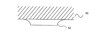
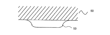
図21Aおよび図21Bは造形物(フレーム)50に付加された補助部材の形状の一例を示す断面図である。図21Aは支台歯と接する部分の肩に角があるタイプの例である。図21Bは支台歯と接する部分が丸められているタイプの例である。このタイプはフレーム50を支台歯に装着する際に、支台歯に接する補助部材53の面上にセメントが存在する場合でも、セメントがその補助部材53の支台歯に接する面からスムーズに排除される。そのため、残留応力が減少するという効果を奏する。
21A and 21B are cross-sectional views showing an example of the shape of the auxiliary member added to the modeled object (frame) 50. FIG. 21A is an example of a type with a corner on the shoulder in contact with the abutment tooth. FIG. 21B is an example of a type in which a portion in contact with the abutment tooth is rounded. In this type, when the
図21Aおよび図21Bに示す例において、造形物50と補助部材52、53の接合部分が角を持たず曲面で構成されているのは、接合部分の強度確保を図っているものである。曲面の半径はあまり大きいとスペーサの設置面積が不足して設計に支障をきたす。また、あまり小さすぎると実質的に角で接合したのと同様の形態となり、セメントが充填されにくくなったり、強度低下につながったり、亀裂の発生箇所になったりする恐れがある。接合部の曲面の半径は支台歯とフレーム間距離の0.1倍から3倍の範囲が好ましい。
In the example shown in FIG. 21A and FIG. 21B, the joined portion between the modeled
もちろん補助形状は、図21A、21Bに示したような造形物側に広がりを持たせた形状だけに制限されるものではなく、適切なセメントスペースの確保と造形物を正しい向きと位置に装着できる限りにおいてその形状に制約を設けるものではない。 Of course, the auxiliary shape is not limited to the shape having a spread on the side of the modeled object as shown in FIGS. 21A and 21B, and it is possible to secure an appropriate cement space and attach the modeled object in the correct orientation and position. As long as the shape is not limited.
補助部材は、この他に長い帯状のものを複数本設けた形状とする事もできる。このような補助形状は、例えば、ステントなど広い面積で患者口腔内に設置される補綴物への適用が好ましい。 In addition to this, the auxiliary member may have a shape in which a plurality of long strips are provided. Such an auxiliary shape is preferably applied to a prosthesis installed in a patient's oral cavity with a large area such as a stent.
次に、補助形状データ生成部27はフレームを正しい向きで正しい位置に装着するのに必要充分な補助部材の数と、補助部材の効果的な配置位置を求める。補助形状データ生成部27は、構造物データ22で示されるフレームの形状に基づいて、支台歯にフレームを装着したときに、その方向が一意に決定されるように個数と場所を決定する。フレームを支台歯に合着する際、その力の方向は限られるので、経験則を用いることにより、補助部材の個数と場所をある程度決定することができる。
Next, the auxiliary shape
例えば、構造物が単冠の場合は、少なくとも2個の補助部材が用いられる。この単冠の場合、補助部材の個数に上限はないが、3個から12個が好ましい。また、構造物がブリッジなどのように、複数の支台歯装着部位がある補綴物である場合は、支台歯装着部位ごとに上述の個数の補助形状データを設ける事が望ましい。 For example, when the structure is a single crown, at least two auxiliary members are used. In the case of this single crown, there is no upper limit to the number of auxiliary members, but 3 to 12 are preferable. Further, when the structure is a prosthesis having a plurality of abutment tooth mounting parts such as a bridge, it is desirable to provide the above-mentioned number of auxiliary shape data for each abutment tooth mounting part.
補助部材の配置場所として、例えば、前歯にあっては切端から見て唇側面、舌即面、近心面、遠心面のうちいずれか1箇所以上と、これらの中間点即ち舌側面と近心面の接続部付近、近心面と唇側面の接続部付近、唇側面と遠心面の接続部付近、遠心面と舌側面の接続部付近のうちいずれか1箇所以上にそれぞれ1個以上補助部材を設ける事が望ましい。 As the location of the auxiliary member, for example, in the case of anterior teeth, one or more of the lip side surface, the tongue immediate surface, the mesial surface, and the distal surface as viewed from the cutting edge, and the intermediate point between these, that is, the tongue side surface and the mesial surface One or more auxiliary members each at one or more of the vicinity of the connection portion of the face, the vicinity of the connection portion of the mesial surface and the labial surface, the connection portion of the labial surface and the distal surface, and the vicinity of the connection portion of the distal surface and the lingual surface It is desirable to provide
臼歯にあっては、例えば、頬側面、舌側面、近心面、遠心面のうちいずれか1箇所以上と、これらの中間点即ち頬側面と遠心面の接続部付近、遠心面と舌側面の接続部付近、舌側面と近心面の接続部付近、近心面と頬側面の接続部付近のうちいずれか1箇所以上にそれぞれ1個以上、補助部材を設ける事が望ましい。 For molars, for example, one or more of the buccal lateral surface, lingual lateral surface, mesial surface, and distal surface, and the midpoint between these, that is, the connection between the buccal lateral surface and the distal surface, the distal surface and the lateral surface of the tongue It is desirable to provide one or more auxiliary members at each one or more of the vicinity of the connecting portion, the vicinity of the connecting portion of the tongue side surface and the mesial surface, and the vicinity of the connecting portion of the mesial surface and the cheek side surface.
こうして生成された補助形状データは記録部11において、構造物データ22に付加される。すなわち、それまでの構造物データ22は、補助形状データ生成部により、上書き保存される。
The auxiliary shape data generated in this way is added to the
補助形状データは、フレームを正しい向きで正しい位置に支台歯に装着する上で大きな効果を発揮する。また、補助形状データにより、設定したとおりの適切なセメントスペースを確保する事ができる。 The auxiliary shape data is very effective in mounting the frame on the abutment tooth at the correct position in the correct orientation. In addition, the auxiliary shape data can ensure an appropriate cement space as set.
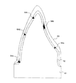
図22は補助形状データが付加された構造物データ22を用いて、積層造形装置100が製造したフレームを、支台歯に装着した様子を横から見た断面図である。図22に示す例では、支台歯61とフレーム63の間には、接着材料62が充填されている。そして、支台歯61に対するフレーム63の位置および向きを固定する補助部材64a〜64eが支台歯61とフレーム63との間に設けられている。
FIG. 22 is a cross-sectional view of a state in which the frame manufactured by the
以上の項目を考慮して作成される補助形状データは適切なセメントスペースを高精度で確保するのに大きな効果をもたらす。また、補助形状はフレームなどの造形物を支台歯に装着する際、セメントスペースが遊びとなって正確な位置決めを妨げる要因になるという問題の発生を防ぎ、設計通りに正確な向きと位置を一意に決定するためのガイドとして機能する。 The auxiliary shape data created in consideration of the above items has a great effect in ensuring an appropriate cement space with high accuracy. In addition, the auxiliary shape prevents the problem that the cement space becomes a play and hinders accurate positioning when mounting a shaped object such as a frame on the abutment tooth, and the correct orientation and position as designed. Serves as a guide to uniquely determine.
これらの効果は補綴物を患者に装着する差異、その調整作業を大幅に削減し、またその作業に要求される熟練度も低減される。これは術者の作業および患者の負担や苦痛の減少に大きく寄与する。 These effects greatly reduce the difference in attaching the prosthesis to the patient, the adjustment work thereof, and the skill required for the work. This greatly contributes to the reduction of the operator's work and the burden and pain on the patient.
このように、造形しようとする構造物が、例えばクラウンやブリッジなどのフレームであり、支台歯との合着、接着のためのセメントスペースを付加したり、フレームが正しい位置及び向きを維持して支台歯に位置決めしたりすることが必要とされる場合に、補助形状データ生成部27は、補助形状データを生成することができる。
In this way, the structure to be modeled is a frame such as a crown or a bridge, for example, to add a cement space for attachment and adhesion to the abutment tooth, or to maintain the correct position and orientation of the frame. The auxiliary shape
(ステップS4 構造物データ補正工程)
ステップS4の構造物データ補正工程において、補正部28は作成部15、あるいは補助形状データ生成部27によって生成され、記録部11に記録された構造物データ22を組成データ23に基づいて補正することにより、補正済み構造物データ29を生成し記録部11に記録する。(Step S4 Structure data correction process)
In the structure data correction process of step S4, the
通常歯科で用いられるクラウンやブリッジのフレームは金属、セラミックスなどで製作される事が多い。また、フレームの上層に築盛される材料としては樹脂やセラミックスが多用される。その他、インレーやオンレーなどのように適切な処置を施した穿洞に歯科用セメントや接着剤を介して嵌め込まれる補綴物には金属、樹脂、セラミックスが用いられている。 The crown and bridge frames usually used in dentistry are often made of metal or ceramics. In addition, as materials to be built up on the upper layer of the frame, resins and ceramics are frequently used. In addition, metals, resins, and ceramics are used for prosthetics that are fitted into dental cavities that have undergone appropriate treatment such as inlays and onlays through dental cement and adhesive.
セラミックス系材料は焼結(焼成)によって最終的な強度を発現させるという工程が必須である。これによって高湿度で繰り返し応力のかかる環境下でも長期間その強度を維持し、化学的に安定で生体に対する為害作用がほとんどなく、また、高い明度、透明感や天然歯類似の色調を良く再現した補綴物を提供することを可能にしている。 For ceramic materials, a process of expressing the final strength by sintering (firing) is essential. This maintains its strength for a long time even in an environment of repeated stress at high humidity, is chemically stable and has little harmful effect on the living body, and reproduces high brightness, transparency and color similar to natural teeth. Prosthesis can be provided.
特に、アルミナやジルコニアを主成分とする素材は、クラウンやブリッジなどそれまで金属でしか実用にならなかった用途に適用できる強度と靭性を持つ上に、色調の面でも金属と比較するとより生体組織と調和する色調を持っている。そのため、これらの素材は、最近注目を集めている。 In particular, alumina and zirconia-based materials have strength and toughness that can be applied to applications such as crowns and bridges that have only been practical with metals, and are also more biological in terms of color. It has a color that harmonizes with. Therefore, these materials have recently attracted attention.
焼成工程の実施は上述の利点をもたらす反面、焼成後に収縮などの寸法や形状の変化を引き起こすという課題も持っている。 While the firing process brings the above-mentioned advantages, it also has the problem of causing changes in size and shape such as shrinkage after firing.
ステップS4の構造物データ補正工程は、例えば、このような焼成による収縮、形状変化、精度低下といった問題を解消するために用いられる。 The structure data correction process in step S4 is used, for example, to solve such problems as shrinkage, shape change, and accuracy reduction due to firing.
補正部28は焼成後に構造物データ22にできる限り近い構造物となるように予め収縮や変形の分だけ構造物データ22に補正を施す。以下では、焼成による収縮の分だけ補正する例を示すが、補正部28による補正は、収縮分に限られない。例えば、焼成工程での変形や膨張等の変化分を補正することもできる。この補正量(収縮量)の算出には組成データ23および変化量データ30が用いられる。組成データ23は、積層造形装置100が積層造形しようとする構造物に用いられる材料の組成を表すデータである。例えば、上記のフレームを、粉末ジルコニアを積層造形によって造形しようとした場合、組成データ23には、粉末ジルコニアとその比重を示すデータが記録される。
The
変化量データ20は、積層造形される構造物に用いられうる様々な材料の組成と、それぞれの材料の焼結による変化の量を示す変化量データとを対応づけて記録したデータである。下記表1に、変化量データ20の内容の一例を示す。下記表1に示す例においては、造形物の組成、比重、および焼結による収縮量が一組のレコードとして記録されている。なお、変化量データ20の内容は下記表1に限られない。
The
例えば、粉末ジルコニアを積層造形によって造形しようとしたとき、組成データ23で示される造形物の比重が5.82であるとすると、補正部28は、上記表1に示す変化量データ20を参照して、比重5.82におけるジルコニアの収縮量19.5を得ることができる。補正部28は、収縮量19.5に対応する分だけ構造物データ22が示す構造物を拡大して補正済み構造物データ29を生成する。
For example, when trying to model powder zirconia by additive modeling, if the specific gravity of the modeled object indicated by the
これにより焼成によって生じる収縮を見込んだ補正済み構造物データ29が得られる。補正済み構造物データ29は記録部11に記録される。
As a result, corrected
なお、構造物を拡大・縮小する計算には、例えば、3次元CADやCAMで用いられている拡大・縮小の計算式を適用することができる。例えば、原点と構造物の各部間との距離を必要倍して得られる距離に、構造物の各部を配置しなおすことで拡大、縮小が行われる。また、補正部28は、3次元空間における座標変換公式(例えば、アフィン変換等)を適用して、構造物データ22の補正してもよい。
For the calculation for enlarging / reducing the structure, for example, the enlargement / reduction calculation formula used in three-dimensional CAD or CAM can be applied. For example, enlargement or reduction is performed by rearranging each part of the structure to a distance obtained by multiplying the distance between the origin and each part of the structure as necessary. The
なお、上記例では、補正部28は、変化量データ30に含まれる収縮量を用いて補正を行っているが、補正部28が変化量データ30を使って収縮量を算出する構成であってもよい。例えば、変化量データ30として、比重から収縮量を求めるための関数を材料ごとに記録しておくことで、補正部28は、その関数を用いて収縮量を計算することができる。
In the above example, the
また、補正部28は、上記例のような焼結による収縮を補正する場合に限られない。例えば、補正部28は、樹脂等の材料が乾燥や重合によって変形する量を変化量データから算出し、その変形を補う補正をしてもよい。なお、樹脂等の材料が乾燥や重合によって変形する場合と、セラミックスが焼結によって変形する場合とでは変形のメカニズムや変形の程度、形状変化の傾向などは異なる。これら両方の変形を補正する場合には、それぞれの変形について、変化量データや、変化量の計算、補正の計算が必要となる。このように、補正部28は、様々な材料や変形メカニズムに対応した適切な補正を施すことができる。
Moreover, the correction |
また、乾燥や重合による変化および焼結による変化のいずれの場合も、寸法の変化とそれに伴う形状変化という2つの現象が起こる場合が多い。そのため、補正部28は、これらのそれぞれの現象について変化量の算出および補正計算を行ってもよい。
Also, in both cases of changes due to drying and polymerization and changes due to sintering, two phenomena often occur, that is, a change in dimensions and a change in shape associated therewith. Therefore, the
(ステップS5 支持部材データ生成工程)
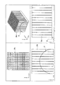
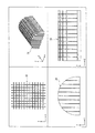
ステップS5の支持部材データ生成工程において、外形生成部5と支持部材生成部7が、補正部28が作成した補正済み構造物データ29を用いて、構造物を支持する支持部材の形状を表す支持部材データ25を作成する。以下、一例として、補正済み構造物データ29が表す構造物がステップS4で説明したブリッジのフレームである場合について説明する。(Step S5 support member data generation process)
In the support member data generation process of step S5, the outer
図3Bは、支持部材生成部7が作成した支持部材データ25が表す支持部材の例を示す図である。図3Bに示す支持部材は、図3Aに示すフレームが積層造形装置100で形成される際に、フレームを後述する造形テーブル上に支持するための支持部材である。すなわち、図3Bに示す支持部材の上に、図3Aに示す構造物であるフレームが形成される。
FIG. 3B is a diagram illustrating an example of the support member represented by the
図4は、支持部材データ25を作成する処理の一例を示すフローチャートである。まず、外形生成部5は、記録部11に記録された補正済み構造物データ29を読み込んで、補正済み構造物データ29が表す構造物を、基礎平面に対して、造形しやすい向きに回転させる(ステップS11)。基礎平面は、構造物を形成するために積層される造形層の基礎となる平面である。造形データ作成システム1における処理においては、基礎平面を例えば、xy平面とすることができる。なお、積層造形装置100においては、基礎平面は、例えば、造形テーブルである。
FIG. 4 is a flowchart illustrating an example of processing for creating the
補正済み構造物データ29が表す構造物であるフレームが、基礎平面に対してどのような向きで配置されるかによって、基礎平面と構造物との間の空間の形状が変わる。基礎平面と構造物との間の空間の形状が変わると、その空間に配置される支持部材の形状も変わる。そこで、構造物の配置は、支持部材に用いられる材料の量が最小になるような配置、または支持部材および構造物の造形時間が最短になるような配置になるように決定されることが好ましい。このような配置の決定要素のうちどちらかを優先させるか、あるいは両立させるように構造物の基礎平面に対する配置が決定されることが好ましい。
The shape of the space between the foundation plane and the structure changes depending on the orientation of the frame, which is the structure represented by the corrected
また、このステップで、フレームを、支台歯側の面を下(基礎平面側)にして配置すると、フレームの支台歯側が支持部材により支持される構造となる。このような構造になると、補助部材と支持部材との境界が不明確になる場合がある。また、支台歯に接する側の空間が狭いので造形、焼成工程終了後の補助部材除去工程で、指や道具が入りにくく、補助形状を取り除きにくくなる場合が多くなる。これらの問題の発生を事前に回避し、除去工程がスムーズに実施できるようにするため、フレームは支台歯側の面を上向きにした状態で支持部材データが生成されることが好ましい。 In this step, when the frame is arranged with the surface on the abutment tooth side down (the base plane side), the abutment tooth side of the frame is supported by the support member. In such a structure, the boundary between the auxiliary member and the support member may be unclear. In addition, since the space on the side in contact with the abutment tooth is narrow, it is difficult for the fingers and tools to enter and the auxiliary shape to be removed in the auxiliary member removing step after the shaping and firing steps. In order to avoid the occurrence of these problems in advance and perform the removal process smoothly, it is preferable that the support member data is generated with the surface of the frame facing the abutment tooth side upward.
外形生成部5は、例えば、構造物を回転させ、様々な配置において、基礎平面と構造物との間の空間の体積を計算する。外形生成部5は、様々な配置のうち、例えば、前記体積が最小となる状態を、構造物を形成する際の配置として選択することができる。
For example, the
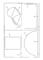
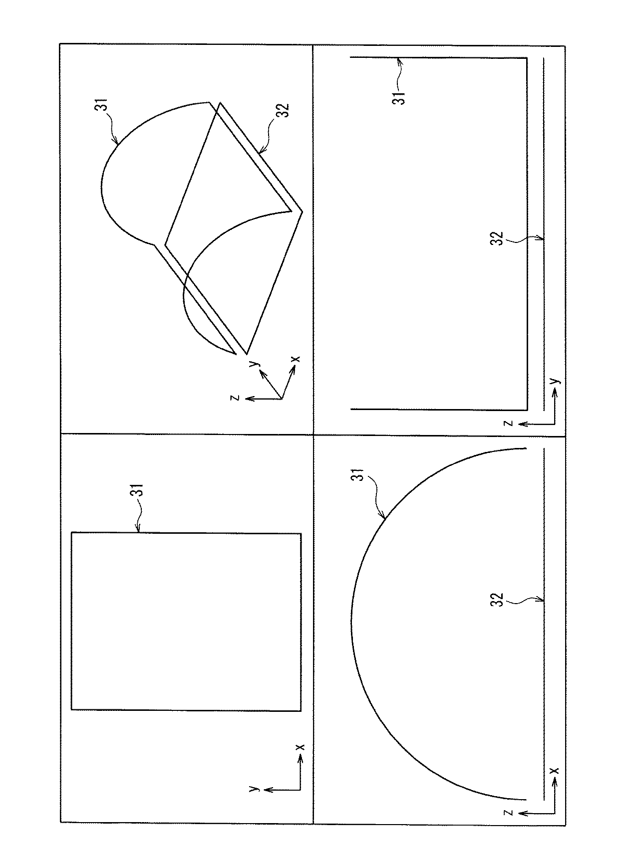
図5は、補正済み構造物データ29が表す構造物31が、xyz座標上に配置された状態を表示する画面の例を示す図である。図5に示す画面において、右上の画像は斜め上から見た構造物31の形状、右下の画像はx軸方向から見た構造物31の形状、左上の画像はz軸方向からみた構造物31の形状、左下の画像はy軸方向から見た構造物31の形状をそれぞれ表している。図5に示す画面におけるxyz座標は、例えば、基礎平面に垂直な方向をz軸に、基礎平面の面をxy平面に対応させた座標とすることができる。なお、図5に示す画面で表示される構造物31の形状は、説明を簡単にするため、フレームの形状ではなく単純な形状とされている。以下に示す図6〜13においても、図5と同様に、補正済み構造物データ29で表される構造物31および支持部材データ25で表される支持部材は単純な形状で表されている。
FIG. 5 is a diagram illustrating an example of a screen that displays a state in which the
外形生成部5は、補正済み構造物データ29が表す構造物31の基礎平面に対する高さを、造形しやすい適切な高さに設定する(ステップS12)。外形生成部5は、例えば、記録部11に予め設定されている高さを表すデータを、構造物31の基礎平面に対する高さに設定することができる。構造物31の基礎平面に対する高さは、支持部材に用いられる材料の量を少なくするためには、なるべく低い方が好ましい。しかし、構造物が基礎平面に対して低すぎると、支持部材から構造物を取り外しにくくなるので、構造物を取り出しやすい程度の高さを保つことが好ましい。
The
外形生成部5は、構造物31の形状をz軸方向からxy平面すなわち基礎平面に投影した形の平面を作成する(ステップS13)。図6は、構造物31の形状をxy平面に投影した平面32を表示する画面の例を表す図である。
The
外形生成部5は、構造物31を投影した平面32と、構造物31との間の空間を、例えば、ルールド面等で埋めてこの空間の外形を生成する。図7は、外形データ24が表す、構造物31と基礎平面(xy平面)との間の空間の外形33を表示する画面の例を表す図である。例えば、構造物31がフレームである場合、フレームの最大輪郭線で構成される面とフレームを基礎平面に投影した平面32との間の空間の外形を表すデータが外形データ24となる。外形データ24は、前記空間の周囲全てを囲む外形を表す必要はなく、少なくとも一部の外形を表すデータであればよい。
The outer
外形データ24の形式は、例えば、閉じたサーフェスとしてもソリッドとしてもよい。外形データ24の形式は、例えば、外形生成部5の機能を実現するソフトウエアにおいて扱われるデータの形式に依存する。
The form of the outline data 24 may be, for example, a closed surface or a solid. The format of the outline data 24 depends on, for example, the format of data handled by software that implements the function of the
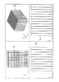
支持部材生成部7は、外形データ24で表される空間内に、所定の断面形状を有する複数の柱状体または板状体を並べることにより、支持部材34を生成する。支持部材34は、例えば、xy平面に垂直に一定間隔で並べられた複数の柱状体または板状体によって形成される。図8は、xy平面に垂直に等間隔で並べられた柱状体34aを表示する画面の例を表す図である。図8に示す例のように、井桁構造の薄壁の集合体を支持部材34にすることができる。支持部材34は、xy平面に垂直な板形状を縦横に交差させた構造であってもよい。
The support
支持部材生成部7が、支持部材34の形状を表す支持部材データ25を生成する方法として、例えば、論理演算による方法、または、単純に柱状体あるいは板状体を並べて外形データ24が表す外形でトリムする方法等がある。
As a method for the support
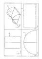
論理演算により支持部材データ25を生成する方法の一例を説明する。例えば、支持部材生成部7は、支持部材34の外形33を定義する形状(図7参照)のデータと、図8に示すように等間隔に並べられた柱状体34a(図8参照)のデータとで論理積演算する。図9は、柱状体34aに外形33を重ね合わせた状態を表示する画面の例を表す図である。論理積演算の結果、外形33と柱状体34aの両方の形状に含まれる部分だけが残って支持部材34の形状が得られる。図10は、支持部材34の形状を表示する画面の例である。図10に示す支持部材34の形状と、目的とする構造物31の形状(図5参照)とを論理和演算することによって、両方の形状が足し算される。その結果、造形しようとする造形物の形状が得られる。このようにして得られる造形物の形状は、目的とする構造物31の形状と支持部材34の形状とが合成された形状である。図11は、目的とする構造物31と支持部材34とで構成される造形物を表示する画面の例を表す図である。図11の画面は、支持部材34の上に構造物31が支持される状態を示している。
An example of a method for generating the
次に、トリムにより支持部材データ25を生成する方法の一例を説明する。図8に示すように並べられた柱状体34aに、外形33(図7参照)を重ね合わせてトリムすることにより、支持部材34の形状を表す支持部材データ25が生成される。図9は、柱状体34aに外形33を重ね合わせた状態を表示する画面の例を表す図である。支持部材生成部7は、柱状体34aのうち外形33内に含まれる部分以外の部分をトリムすることにより、支持部材34の形状を形成する。トリムされた柱状体34aによって形成された支持部材34の形状は、例えば、図10のように表示される。
Next, an example of a method for generating the
このようにして形成された支持部材34の形状は、構造物31を基礎平面上に支持することができる形状である必要がある。図11は、支持部材34の上に構造物31が支持される状態を表示する画面の例を表す図である。図11に示すように、支持部材34は、構造物31の基礎平面(xy平面)側の面を全体的に支持する構造になっている。この構造により、構造物31は、焼成工程において、崩れたり、ガラス化中に垂れたり、変形したりするなどの形状変化が防止される。
The shape of the
柱状体の断面形状は、正方形か長方形が好ましい。この場合、柱の側面が壁となる。その壁の厚みと、柱状体の断面形状における正方形または長方形の一辺の長さによって、支持部材34の強度が変わる。また、支持部材34に用いられる材料の強度によっても、支持部材34の強度は変わる。支持部材34の求められる強度は、造形時に構造物31の重量によって押しつぶされない程度、且つ焼結時に構造物31の重さで押しつぶされない程度が望ましい。一方で、壁の厚みを厚くしすぎると、支持部材34が構造物31に接する面積が大きくなり、焼結後に、支持部材34を構造物31から除去した際に、支持部材34の残骸が構造物31に残りやすくなる。
The cross-sectional shape of the columnar body is preferably square or rectangular. In this case, the side surface of the column becomes a wall. The strength of the
したがって、支持部材34を構成する柱状体間の壁の厚みは、構造物31が造形時に変形しない程度に厚く、かつ造形終了後、あるいは焼成後に手指で簡単に除去でき、かつ支持部材34除去後も構造物31に残骸が残らない程度に薄くすることが好ましい。支持部材生成部7は、支持部材34に用いられる材料の組成が決まれば、壁の厚みを決めることができる。以下、支持部材34を構成する柱状体の壁の厚みを求める方法の例について説明する。
Therefore, the thickness of the wall between the columnar bodies constituting the
(支持部材34の壁の厚み計算方法例)
記録部11には、支持部材34に用いられる材料の組成を表す組成データ23が予め記録されていることが好ましい。例えば、構造物31の設計者が、支持部材34に用いる材料の組成を組成データ23に設定してもよい。支持部材生成部7は、設定された組成データ23を基に、支持部材34の壁の厚みを計算により求めることができる。(Example of a method for calculating the wall thickness of the support member 34)
It is preferable that
前記測定データは、例えば、積層造形装置で、一層の厚みに粉材を散布し、液を射出して形状化させて一定形状のテストピースを形成し、焼成後にテストピースに生じる収縮や変形の量を計測し、焼成前の寸法と比較、検討することによって得られる。 The measurement data is, for example, a layered modeling apparatus, in which a powder material is dispersed in a single layer thickness, and a liquid is injected to be shaped to form a test piece having a fixed shape. It is obtained by measuring the amount and comparing and examining the dimensions before firing.
上記の構造物31の形状、材料を表すデータや、前記測定データは、予め記録部11に記録されていることが好ましい。支持部材生成部7は、これらのデータを用いて、例えば、有限要素法等、一般的な計算方法によって収縮や垂れの生じる部位、方向と大きさを求めることができる。算出した変形の生じる部位、方向と大きさを表すデータは、支持部材34の壁の厚さを求めるのに用いられる。
The data representing the shape and material of the
また、支持部材生成部7は構造物31の重量配分(例えば、構造物31を平面に投影した場合の単位面積あたりの重さ)を、支持部材34の壁の厚みの計算に用いてもよい。場所によって支持部材34にかかる重さが変化する場合、支持部材34の壁の厚みを場所によって変えられる可能性がある。例えば、支持部材生成部7は、単位面積あたりの重さが大きい部分にある支持部材34の壁の厚みを、他の部分より厚くすることができる。
Further, the support
このようにして作製された支持部材自身も焼結による収縮変化を起こし、一般的にその厚みが薄くなる。これは指示部材の除去を容易にするという副次的な効果を有する。すなわち、支持部材データ25は補正済み構造物データ29と外形データ24から生成されるので、支持部材データ25を基に造形された支持部材は、焼結により構造物(フレーム)と同様に収縮する。これにより支持部材を構成する板状体または柱状体の断面積も収縮によって薄くなり、強度が低下する。その結果、焼成後の構造物からの支持部材の除去がより容易になるという利点を有する。
The support member itself thus produced also undergoes shrinkage change due to sintering, and its thickness generally decreases. This has the secondary effect of facilitating removal of the indicator member. That is, since the
(支持部材34が構造物31と接する部分の形状の例)
ここで、支持部材34が構造物31と接する部分の形状の例について説明する。支持部材データ25および補正済み構造物データ29で表される造形物が、積層造形装置100によって造形された後、あるいは焼成工程終了後に、支持部材34は構造物31から除去される。支持部材34が除去された後の構造物には後加工(検索、研磨、バフがけ)が施され、表面が平滑化される。支持部材34を除去する際に、支持部材34のどの部分で折り取ることができるかは、後加工の作業量や所要時間に大きく影響する。後加工を容易にするためには、構造物31と支持部材34が接する部分の近くが折れることが好ましい。すなわち、支持部材34として、構造物31から除去した時に、その残骸が構造物31に残らないような形状を表す支持部材データ25を生成することが好ましい。(Example of the shape of the portion where the
Here, an example of the shape of the portion where the
支持部材生成部7は、支持部材34が構造物31と接する部分の面積がなるべく小さくなるように支持部材34の壁の厚みを算出することが好ましい。支持部材34が構造物31と接する部分の面積を小さいと、支持部材34を除去した後に構造物31に残る残骸が少なくなる。
The
また、支持部材生成部7は、支持部材34を構成する柱状体または板状体と構造物31とが接する部分において、柱状体または板状体の壁の厚みを他の部分よりも薄くすることができる。
In addition, the support
また、支持部材生成部7は、構造物31において、支持部材34が接する部分の周辺部を構造物31の内面方向へ窪ませるように構造物データ22を修正してもよい。図12Aは、支持部材34が接する部分の周辺部を窪ませた場合の支持部材34と構造物31の断面形状を示す図である。図12Aに示す例では、支持部材34と構造物31が接する部分の周辺部に窪み31aが設けられている。窪み31aの深さは構造物31の厚み以下であることが好ましい。構造物31の破壊防止のためである。
In addition, the support
また、窪み31aの大きさは、後処理で解消できる程度であることが好ましい。例えば、構造物31がブリッジのフレームである場合、窪み31aの面積が構造物31の表面全体に対して、面積比で30%程度以上にならないことが好ましい。
Moreover, it is preferable that the magnitude | size of the hollow 31a is a grade which can be eliminated by post-processing. For example, when the
また、支持部材生成部7は、構造物31に接する部分の近くに切り欠きを有する支持部材34を表す支持部材データ25を生成してもよい。図12Bは、切り欠きを有する支持部材34の断面形状を示す図である。図12Bに示す例では、支持部材34と構造物31が接する部分の根元に切り欠き34bが設けられている。これにより、支持部材34は、除去されるときに根元に近い切り欠き34a部分で折れやすくなり、残骸を構造物31に残しにくくなる。
Further, the support
なお、支持部材34を構成する柱状体の断面形状は、正方形または長方形に限られない。例えば、円、楕円、菱形、平行四辺形、五角形、正六角形、ひょうたん型等任意の形状の断面形状を持つ柱状体で支持部材34を構成してもよい。すなわち、断面形状として、三角形よりも多くの角を有する多角形、円形や扇形のような曲面を含む形状等が用いられてもよい。また、これらのうち任意の2種類以上の形状が併用されてもよい。なお、ステップS3における補助部材の断面形状も、支持部材34と同様に形状に構成しうる。
In addition, the cross-sectional shape of the columnar body constituting the
(支持部材34の変形例)
図13および図14は、図10に示す支持部材34の例とは、異なる形状を有する支持部材34の変形例を表示する画面を表す図である。図13に示す支持部材34の形状は、xy平面に垂直な板状体を縦横に交差させた構造であり、それぞれの板状体におけるxy方向の端部が外側へ突出している。図14に示す支持部材34においては、支持部材34を構成する柱状体の断面形状が、x軸に対して略45°の角度を有する辺を持つ正方形となっている。(Modification of support member 34)
FIGS. 13 and 14 are diagrams showing a screen displaying a modification of the
(ステップS6 断面データ生成工程)
ステップS6において、断面生成部9は、支持部材データ25で表される支持部材34と、補正済み構造物データ29で表される構造物31とで構成される造形物の、基礎平面に略平行な複数の平面それぞれにおける断面形状を表す断面データ26を生成する。(Step S6 Cross-section data generation process)
In step S <b> 6, the cross-section generating unit 9 is substantially parallel to the base plane of the shaped object constituted by the
図15A〜図15Cは、構造物31であるブリッジのフレームと支持部材とで構成される造形物を、互いに所定の間隔を有する複数の平行な面で輪切りにした様子を示す図である。図15A〜15Cにおいては、輪切りにした場合の各断面における構造物31あるいは支持部材の形状が、線により示されている。図15Aは、造形物を横から見た図、図15Bは、造形物を斜め上から見た図、図15Cは造形物を上から見た図である。
FIG. 15A to FIG. 15C are views showing a state in which a three-dimensional object composed of a bridge frame and a support member, which is the
断面生成部9は、例えば、図15A〜15Cに示すように、構造物31を所定の間隔(ピッチ)で輪切りにした場合の、各断面における構造物31の2次元の形状を断面データ26として生成する。前記所定の間隔は、構造物31が造形される際の造形層の厚みに応じて決められることが好ましい。
For example, as illustrated in FIGS. 15A to 15C, the cross-section generator 9 uses the two-dimensional shape of the
断面データ26は、例えば、各断面の2次元形状をビットマップで表す画像データ群である。各断面の画像において、構造物31に相当する部分は、構造物31が形成される領域であることを示す階調のデータで表される。構造物31を形成する材料または色によって階調を変えて、各断面における構造物31の形状が表されてもよい。図16は、構造物31であるフレームの各断面における画像データの例を示す図である。
The
断面生成部9は、各断面の2次元形状を表す画像データの解像度が、後述する積層造形装置100におけるインクジェットヘッドの解像度に適合するように、画像データのサイズを補正してもよい。例えば、前記インクジェットヘッドのドット密度が、512ドット/36mm(14.2ドット/mm)である場合、これに合うビット間隔になるように画像データのサイズが補正されることが好ましい。
The cross-section generator 9 may correct the size of the image data so that the resolution of the image data representing the two-dimensional shape of each cross-section matches the resolution of the inkjet head in the layered
以上のように、実施の形態1においては、構造物の一例としてブリッジのフレームを造形するためのデータを作成する場合について説明したが、構造物は、ブリッジのフレームに限らない。例えば、矯正用ブラケット・矯正装置、インレー、オンレー、クラウン、ブリッジ、クラウンのフレーム、コア材、インプラント上部構造、人工歯、各種模型、実験用治具、実験用構造材などの歯科用構造材、人工歯、術前評価などに用いられる顎骨形状模型、インプラント埋入時に用いる方向・位置決め用治具を構造物とすることができる。さらに、構造物は、歯科用材に限られず、他の分野における任意の形状の構造物を目的とする構造物とすることができる。 As described above, in the first embodiment, the case of creating data for modeling the bridge frame as an example of the structure has been described. However, the structure is not limited to the bridge frame. For example, orthodontic brackets and orthodontic devices, inlays, onlays, crowns, bridges, crown frames, core materials, implant superstructures, artificial teeth, various models, experimental jigs, experimental structural materials, and other dental structural materials, An artificial tooth, a jawbone model used for preoperative evaluation, and a direction / positioning jig used for implant placement can be used as a structure. Furthermore, the structure is not limited to a dental material, and can be a structure intended for a structure of any shape in other fields.
(実施の形態2)
実施の形態2は、実施の形態1における造形データ作成システム1で作成される断面データ26と、積層造形装置100とを用いて、例えば、フレーム等のような構造物を製造するための製造方法に関する。積層造形装置100は、造形テーブル上に、その層の一部を選択的に形状化させた造形層を積層することによって所望の造形物を製作する装置である。(Embodiment 2)
The second embodiment is a manufacturing method for manufacturing a structure such as a frame using the
図17は、積層造形装置100の概略構成を示す斜視図である。図17において、互いに直交する水平方向軸をX軸およびY軸、上下方向軸をZ軸とする。図17に示すように、積層造形装置100は、造形テーブル110、升120、粉体フィーダ130、液剤フィーダ140、掻き取り部材150、光源160を備える。図11では、構造を理解しやすくするために、升120が二点鎖線で示され、その中の造形テーブル110が透視されるように図示されている。
FIG. 17 is a perspective view illustrating a schematic configuration of the
造形テーブル110は、Z軸方向に昇降可能であり。升120は、造形テーブル110の水平方向の周囲を取り囲む壁を備える。粉体フィーダ130は、粉体を造形テーブル110上に散布する。液剤フィーダ140は、液剤を造形テーブル110上に射出する。掻き取り部材150は、造形テーブル110上に散布された粉体の上面を平面にならす。
The modeling table 110 can be moved up and down in the Z-axis direction. The
光源160は、射出された液剤を光重合させるための光源、または液剤の乾燥を促進させるための熱線光源として必要に応じて設ける事ができる。
The
積層造形装置100は、コンピュータ(図示せず)を備える。このコンピュータは、所定の制御プログラムに基づいて、造形テーブル110、粉体フィーダ130、液剤フィーダ140、掻き取り部材150および光源160の動作を制御する。
The
粉体フィーダ130は、Y軸方向において、造形テーブル110の寸法と略同一幅の粉体散布幅を有する。粉体フィーダ130は、粉体を散布しながらX軸方向に移動することにより、造形テーブル110の全面に粉体を散布する。
The
粉体フィーダ130は、例えば、スライダ(図示せず)によって、X軸方向に移動させられる。前記コンピュータは、前記スライダを駆動するためのドライバに制御信号を送ることによって、粉体フィーダ130を制御することができる。
The
掻き取り部材150は、その下端にY軸方向に延びた掻き取り端縁151を有する。掻き取り端縁151を升120の上面122に摺動させながら、掻き取り部材150はX軸方向に移動する。掻き取り部材150は、例えば、スライダ(図示せず)によって、X軸方向へ移動させられる。
The scraping
液剤フィーダ140は、例えば、インクジェットヘッドである。液剤フィーダ140は、一軸案内機構148によりY軸方向に移動する。そして、この一軸案内機構148は図示しない駆動機構によりX軸方向へ駆動される。すなわち、液剤フィーダ140は、造形テーブル110上をX軸方向およびY軸方向に走査しながら、所望する位置にて造形テーブル110に向かって液剤を射出する。積層造形装置100は、例えば、一軸案内機構148において液剤フィーダ140をY軸方向へ移動するYスライダ(図示せず)と、液剤フィーダ140をX軸方向へ移動させるXスライダ(図示せず)を備えてもよい。
The
この液剤フィーダ140の動作は、前記コンピュータによって制御される。前記コンピュータは、前記Xスライダおよび前記Yスライダを駆動するためのドライバに制御信号を送ることによって液剤フィーダ140を制御する。また、コンピュータは、例えば、造形データ作成システム1で生成された断面データ26等に基づいて、液剤フィーダ140が液剤を射出する位置を制御することできる。
The operation of the
造形テーブル110は、図示しない駆動機構により一定ピッチで下降される。この1ピッチが、造形テーブル110上に積層される粉体の1層の厚さに対応する。すなわち、1ピッチに相当する厚さずつ、造形テーブル110上に粉体が積層されていく。造形テーブル110は、例えば、スライダ(図示せず)によって、上下方向へ移動させられる。 The modeling table 110 is lowered at a constant pitch by a driving mechanism (not shown). This one pitch corresponds to the thickness of one layer of powder laminated on the modeling table 110. That is, the powder is laminated on the modeling table 110 by a thickness corresponding to one pitch. The modeling table 110 is moved in the vertical direction by a slider (not shown), for example.
次に、積層造形装置100が、造形物を製造する方法について図18を用いて詳細に説明する。
Next, a method in which the layered
図18Aは、造形テーブル110上にすでに粉体による造形層が、複数層(図では2層)積層された状態を示している。図18Aに示す状態において、造形テーブル110上の堆積された複数の造形層のうち最上層171は、液剤の形状化により形成された固結部172を含む。最上層171の1つ前に堆積された造形層173も、液剤の形状化により形成された固結部174を含む。
FIG. 18A shows a state in which a plurality of layers (two layers in the drawing) of powdered layers are already stacked on the modeling table 110. In the state shown in FIG. 18A, the
図18Aに示す状態において、粉体フィーダ130は、X軸方向に移動しながら、そのスリット132から造形テーブル110上に粉体134を散布する。
In the state shown in FIG. 18A, the
次に、図18Bに示すように、掻き取り部材150が、X軸方向に移動して、粉体134の上面を升120の上面122と同一の高さに規制する。これにより最上層171上に、均一の厚みを持つ粉体層175が形成される。
Next, as shown in FIG. 18B, the scraping
次いで、図18Cに示すように液剤フィーダ140が移動しながら、粉体層175中の造形物を形成する位置に向かって液剤を射出する。液剤が射出される位置は、断面データ26に基づいて制御される。例えば、断面データ26が表す断面形状を、粉体層175に形成するように、液剤フィーダ140が液剤を射出する。その結果、粉体層175において、断面データ26で表される断面形状が形成される。すなわち、液剤フィーダ140が射出した液剤が、紛体層175の断面データ26で表される断面形状の部分にバインダー液として含浸する。
Next, as shown in FIG. 18C, the
次いで、図18Dに示すように、光源160により光を照射して、粉体層175に付与された液剤を重合させ形状化させる。液剤が形状化する際、液剤が付与された領域内の粉体が一体化される。かくして、粉体層175中に固結部177が形成される。形成される固結部177の形状は、断面データ26によって表されたある1つ断面における断面形状である。
Next, as shown in FIG. 18D, light is irradiated from the
次いで、造形テーブル110を所定のピッチだけ降下させて、上記の図18A〜図18Dに示す動作を行う。上記の図18A〜図18Dに示す動作を、断面データ26に含まれる断面それぞれについて順次繰り返す。
Next, the modeling table 110 is lowered by a predetermined pitch, and the operations shown in FIGS. 18A to 18D are performed. The operations shown in FIGS. 18A to 18D are sequentially repeated for each cross section included in the
最後に、造形テーブル110の未固結の粉体を除去することにより、図18Eに示すように、固結部174、172、177等が一体となった造形物を得ることができる。この造形物は、例えば、焼成炉を用いて焼成される。
Finally, by removing the unconsolidated powder from the modeling table 110, as shown in FIG. 18E, a modeled object in which the
以上の工程を、例えば、実施の形態1における造形データ作成システム1で作成された断面データ26を用いて行うことにより、構造物31およびそれを支持する支持部材34が一体となった造形物を製造することができる。
By performing the above process using, for example, the
以上のような、積層造形装置100の動作は、積層造形装置100が備えるコンピュータが所定の制御プログラムに基づいて積層造形装置100を制御することによって実行することができる。以下、図18に示す動作を実現するための制御プログラムによる制御の一例を説明する。図19は、制御プログラムによって制御される処理の一例を示すフローチャートである。
The operation of the
まず、コンピュータは、造形テーブル110のスライダを駆動するためのドライバに制御信号を送って、造形テーブル110を造形開始位置に移動させる(ステップS21)。造形テーブル110が所定の位置に配置されると、コンピュータは、粉体フィーダ130に移動を開始させる(ステップS22)。コンピュータは、例えば、粉体フィーダ130のスライダを駆動させるドライバに制御信号を送ることにより、粉体フィーダ130を移動させることができる。
First, the computer sends a control signal to a driver for driving the slider of the modeling table 110, and moves the modeling table 110 to the modeling start position (step S21). When the modeling table 110 is placed at a predetermined position, the computer causes the
コンピュータは、粉体フィーダ130の移動開始後一定時間が経過したら、粉体フィーダ130の撒布口を開く(ステップS23)。コンピュータは前記一定時間経過後に粉体フィーダ130が一定速度に達し、加速度がゼロになったと判断することができる。
When a certain time has elapsed after the start of the movement of the
粉体フィーダ130が撒布口を開いて、粉体134を撒布し始めてから一定距離を移動した時点(あるいは一定時間経過した時点)で、コンピュータは、粉体フィーダ130の撒布口を閉じる(ステップS24)。その後、コンピュータは、粉体フィーダ130の移動を止めて(ステップS25)、待避場所に戻す(ステップS26)。
When the
次に、コンピュータは、液剤射出パターンを表すデータを読み込む(ステップS27)。液剤射出パターンは、例えば、断面データ26が表すある一断面における断面形状である。コンピュータは、液剤フィーダ140の移動を開始する(ステップS28)。移動開始後、一定時間経過した時点で、コンピュータは、液剤フィーダ140が一定速度に達し、その加速度がゼロになったと判断して、液剤の射出を開始する。液剤の射出は、ステップS27で読み込んだデータに従って行われる。一断面分の射出が終了すると、コンピュータは液剤フィーダ140の移動を止める(ステップS30)。
Next, the computer reads data representing the liquid injection pattern (step S27). The liquid agent injection pattern is, for example, a cross-sectional shape in a certain cross section represented by the
コンピュータは、射出した液剤の量が、予め設定されている量に達しているか否か判断する(ステップS31)。液剤の量が設定されている量に達していない場合(ステップS31でNOの場合)、ステップS28〜S31の処理が再度実行される。このように、液剤量が多く設定されている場合はステップS28〜31を複数回繰り返すことで、所定の液剤量を射出することができる。 The computer determines whether or not the amount of the injected liquid agent has reached a preset amount (step S31). When the amount of the liquid agent has not reached the set amount (NO in step S31), the processes in steps S28 to S31 are executed again. As described above, when a large amount of liquid agent is set, a predetermined amount of liquid agent can be injected by repeating steps S28 to S31 a plurality of times.
ステップS31でYESの場合、コンピュータは、液剤フィーダ140を退避位置に戻し(ステップS32)、造形テーブル110を積層ピッチ1回分下降する(ステップS33)。コンピュータは、全積層分について終了するまで、ステップS21〜33の処理を繰り返す(ステップS34)。すなわち、ステップS21〜33までの処理は必要な回数繰り返される。以上が、図18に示す動作を実現するための制御プログラムによる制御の一例である。
If YES in step S31, the computer returns the
図19に示す処理において、ステップS27で読み込む断面データ26として、実施の形態1における造形データ作成システム1で作成されたデータを用いることができる。造形データ作成システム1で作成されたデータを用いることによって、構造物31およびそれを支持する支持部材34が一体となった造形物が製造される。構造物31は、支持部材34に支持された状態で形成されるので、形成過程で崩れにくい。また、支持部材34は、簡単に構造物31から除去でき、かつ構造物31に残骸が残りにくい形状になっている。
In the process shown in FIG. 19, the data created by the modeling
支持部材34を除去した後の構造物31は、外周全面に渡って高さ方向に一回の積層厚み分の段差が生じる。また、インクジェットヘッドの解像度や吐出液量と、粉体の粒子径の組み合わせ等によって、平面方向で細かなぎざぎざが生じる事がある。
In the
例えば、構造物31が、フレームである場合、その表面は平滑ではない。そこで、支持部材34を除去した後の焼成工程において焼結条件(焼成条件)を適切に設定することにより、造形物の表面段差を解消することができる。また焼成工程での加熱作業を焼結、焼成処理とグレーズ処理の2つの処理で構成することによって精度よくかつ表面の滑沢な焼結品、あるいは焼成品を製造する事が可能である。
For example, when the
更に必要があれば造形後の後処理(研削、研磨、バフがけ)を実施してもよい。積層造形装置100において、造形データ作成システム1で作成された断面データ26を用いて形成されるブリッジのフレームは、形成過程で崩れにくく、焼結過程で変形が起こりにくく、かつ支持部材34を除去しても残骸が残りにくい。そのため、後処理によって、フレームの表面を容易に平滑化することができる。また、支台歯との適合精度も実用上十分なレベルにできる可能性が高い。
If necessary, post-processing (grinding, polishing, buffing) after modeling may be performed. In the
また、実施の形態2においては、積層造形装置100が、粉体を積層して層の一部を形状化することによって造形物を製造する方法について説明したが、造形層を積層することによって造形物を製造する方法は、粉体を積層する方法に限られない。例えば、光形状化樹脂を積層して、光を照射することによって層の一部を形状化する光造形方法や、シート材を積層してその一部をカットする方法を用いることもできる。また、粉末素材の層にレーザを照射することによって層の一部を瞬間焼結して形状化する粉末焼結法を用いることもできる。その他の積層造形方法として、例えば、インクジェット法、樹脂押し出し法、シート切断法等を用いることができる。
Moreover, in
また、実施の形態2における積層造形装置100の造形テーブル110に、例えば、テーブル面に平行な回転軸を設けて、造形テーブル110のテーブル面が、上下逆さまになるように回転可能な構成とすることができる。この回転可能な造形テーブル110を使用して積層造形を行う場合の動作の例を説明する。まず、形状化させたい部分に液剤が射出され、次に粉体が一層撒布される。このとき、液剤が射出された部分に撒布された粉体のみが液剤と接触して形状化する。その後、一旦造形テーブルが回転して粉体が撒布された面が逆さまになることにより、形状化しなかった粉体は重力によって落下する。このような動作を繰り返すことにより積層造形が行われる。
In addition, for example, the modeling table 110 of the
Claims (14)
所望の構造物の形状を表す構造物データを入力する構造物データ入力部と、
前記積層造形装置が形成する前記造形物に用いられる材料の組成を表す組成データを記録する組成データ記録部と、
前記造形物に用いられる可能性のある材料の組成と、当該材料の乾燥、重合または焼結による変化の量を示す変化量データとを対応づけて記録する変化量データ記録部と、
前記組成データで示される材料の組成に対応する変化の量を示す変化量データを前記変化量データから取得し、取得した変化量データに基づいて、前記構造物データを用いて形成される造形物が、乾燥、重合または焼結による変化後に前記所望の構造物の形状に近くなるように当該構造物データを補正する補正部と、
前記構造物を前記基礎平面上に配置し、前記配置された前記構造物を前記基礎平面に垂直に投影した投影面と、前記構造物との間の空間の外形を表す外形データを、前記構造物データを用いて生成する外形生成部と、
前記空間の略全体を満たすように形成され、かつ前記基礎平面に対して垂直に設けられた複数の板状体または柱状体で形成され、前記構造物を支持する支持部材の形状を表す支持部材データを生成する支持部材生成部と、
前記基礎平面に略平行な複数の平面それぞれにおける断面形状を表す断面データを、前記構造物データ、前記支持部材データおよび前記外形データに基づいて生成する断面生成部とを備え、
前記組成データ記録部は、前記支持部材に用いられる材料の組成を表す組成データもさらに記録し、
前記支持部材生成部は、前記組成データ記録部に記録された前記組成データを用いて、前記板状体または前記柱状体の水平方向の厚みを求める、造形データ作成システム。Lamination that forms the shaped part as a modeled object by laminating a shaped layer shaped at least partly by irradiating light or impregnating with a binder liquid on a basic plane. A modeling data creation system for creating modeling data representing the shape of the modeled object used in a modeling apparatus,
A structure data input unit for inputting structure data representing the shape of a desired structure;
A composition data recording unit for recording composition data representing a composition of a material used for the modeled object formed by the additive manufacturing apparatus;
A change amount data recording unit that records the composition of a material that may be used for the modeled object and change amount data indicating the amount of change due to drying, polymerization, or sintering of the material in association with each other;
A change amount data indicating an amount of change corresponding to the composition of the material indicated by the composition data is acquired from the change amount data, and a shaped article formed using the structure data based on the acquired change amount data A correction unit that corrects the structure data so as to be close to the shape of the desired structure after changes due to drying, polymerization, or sintering;
The structure is arranged on the base plane, and outline data representing the outline of a space between the structure and a projection plane obtained by projecting the arranged structure perpendicular to the base plane is used as the structure. An outline generation unit that generates using object data;
A support member that is formed so as to fill substantially the entire space and that is formed of a plurality of plate-like bodies or columnar bodies provided perpendicular to the base plane and that represents the shape of the support member that supports the structure. A support member generator for generating data;
A cross-section generator that generates cross-sectional data representing a cross-sectional shape in each of a plurality of planes substantially parallel to the base plane based on the structure data, the support member data, and the outer shape data ;
The composition data recording unit further records composition data representing the composition of the material used for the support member,
The modeling data creation system , wherein the support member generation unit obtains a horizontal thickness of the plate-like body or the columnar body using the composition data recorded in the composition data recording unit .
所望の構造物の形状を表す構造物データを入力する構造物データ入力部と、
前記積層造形装置が形成する前記造形物に用いられる材料の組成を表す組成データを記録する組成データ記録部と、
前記造形物に用いられる可能性のある材料の組成と、当該材料の乾燥、重合または焼結による変化の量を示す変化量データとを対応づけて記録する変化量データ記録部と、
前記組成データで示される材料の組成に対応する変化の量を示す変化量データを前記変化量データから取得し、取得した変化量データに基づいて、前記構造物データを用いて形成される造形物が、乾燥、重合または焼結による変化後に前記所望の構造物の形状に近くなるように当該構造物データを補正する補正部と、
前記構造物を前記基礎平面上に配置し、前記配置された前記構造物を前記基礎平面に垂直に投影した投影面と、前記構造物との間の空間の外形を表す外形データを、前記構造物データを用いて生成する外形生成部と、
前記空間の略全体を満たすように形成され、前記構造物を支持する支持部材の形状を表す支持部材データを生成する支持部材生成部と、
前記基礎平面に略平行な複数の平面それぞれにおける断面形状を表す断面データを、前記構造物データ、前記支持部材データおよび前記外形データに基づいて生成する断面生成部とを備え、
前記構造物データ入力部は、前記所望の構造物が他の物体に装着されるものである場合に、前記物体と前記構造物との相対的な位置関係を示す関係データをさらに入力し、
前記関係データに基づいて、前記物体と前記構造物との前記位置関係を固定するための部材を表す補助形状データを生成し、前記構造物データに付加する補助形状データ生成部をさらに備え、
前記補助形状データ生成部は、前記物体と前記構造物との間に設けられた板状体または柱状体を表すデータを、補助形状データとして生成するものであって、前記組成データ記録部に記録された前記組成データを用いて、前記板状体または前記柱状体の断面積を求めることで前記補助形状データを生成する、造形データ作成システム。 Lamination that forms the shaped part as a modeled object by laminating a shaped layer shaped at least partly by irradiating light or impregnating with a binder liquid on a basic plane. A modeling data creation system for creating modeling data representing the shape of the modeled object used in a modeling apparatus,
A structure data input unit for inputting structure data representing the shape of a desired structure;
A composition data recording unit for recording composition data representing a composition of a material used for the modeled object formed by the additive manufacturing apparatus;
A change amount data recording unit that records the composition of a material that may be used for the modeled object and change amount data indicating the amount of change due to drying, polymerization, or sintering of the material in association with each other;
A change amount data indicating an amount of change corresponding to the composition of the material indicated by the composition data is acquired from the change amount data, and a shaped article formed using the structure data based on the acquired change amount data A correction unit that corrects the structure data so as to be close to the shape of the desired structure after changes due to drying, polymerization, or sintering;
The structure is arranged on the base plane, and outline data representing the outline of a space between the structure and a projection plane obtained by projecting the arranged structure perpendicular to the base plane is used as the structure. An outline generation unit that generates using object data;
A support member generating unit that generates support member data representing a shape of a support member that is formed so as to fill substantially the entire space and supports the structure;
A cross-section generator that generates cross-sectional data representing a cross-sectional shape in each of a plurality of planes substantially parallel to the base plane based on the structure data, the support member data, and the outer shape data;
The structure data input unit further inputs relation data indicating a relative positional relationship between the object and the structure when the desired structure is attached to another object,
An auxiliary shape data generating unit that generates auxiliary shape data representing a member for fixing the positional relationship between the object and the structure based on the relationship data, and adds the auxiliary shape data to the structure data ;
The auxiliary shape data generation unit generates data representing a plate-like body or a columnar body provided between the object and the structure as auxiliary shape data, and records the data in the composition data recording unit. The modeling data creation system which produces | generates the said auxiliary | assistant shape data by calculating | requiring the cross-sectional area of the said plate-shaped object or the said columnar body using the said composition data .
前記積層造形装置が備える上下に移動可能な造形テーブル上に、所定の厚みの造形層を形成する層形成工程と、
前記造形層の少なくとも一部であって、前記断面データが表す断面形状に応じた形状の部分のみ選択的に光を照射するかまたはバインダー液を射出し、含浸させて形状化する造形工程と、
前記造形テーブルを前記所定の厚み分降下させる降下工程と、
前記層形成工程および前記形状化工程を、前記断面データが表す前記複数の平面それぞれについて順次繰り返すことによって、前記造形層を積層する積層工程と、
前記積層工程で積層された前記造形層において、前記形状化工程で形状化された部分以外の部分を除去することによって、前記支持部材によって前記造形テーブル上に支持された状態の前記構造物を形成する除去工程とを備える製造方法。A manufacturing method for manufacturing the structure using the cross-sectional data created by the modeling data creation system according to any one of claims 1 to 11 and the layered modeling apparatus,
A layer forming step of forming a modeling layer of a predetermined thickness on a modeling table that is movable up and down with the layered modeling apparatus;
A modeling step that is at least a part of the modeling layer and selectively irradiates light only with a portion corresponding to a cross-sectional shape represented by the cross-sectional data, or injects a binder liquid and impregnates it into a shape, and
A lowering step of lowering the modeling table by the predetermined thickness;
A laminating step of laminating the modeling layer by sequentially repeating the layer forming step and the shaping step for each of the plurality of planes represented by the cross-sectional data;
In the modeling layer laminated in the laminating step, the structure in a state of being supported on the modeling table by the support member is formed by removing a portion other than the portion shaped in the shaping step. And a removing process.
所望の構造物の形状を表す構造物データを入力する構造物データ入力処理と、
前記積層造形装置が形成する前記造形物に用いられる材料の組成を表す組成データを記録する組成データ記録部と、前記造形物に用いられる可能性のある材料の組成と、当該材料の乾燥、重合または焼結による変化の量を示す変化量データとを対応づけて記録する変化量データ記録部とにアクセスし、前記組成データで示される材料の組成に対応する変化の量を示す変化量データを前記変化量データから取得し、取得した変化量データに基づいて、前記構造物データを用いて形成される造形物が、乾燥、重合または焼結による変化後に前記所望の構造物の形状に近くなるように当該構造物データを補正する補正処理と、
前記構造物を前記基礎平面上に配置し、前記配置された前記構造物を前記基礎平面に垂直に投影した投影面と、前記構造物との間の空間の外形を表す外形データを、前記構造物データを用いて生成する外形生成処理と、
前記空間の略全体を満たすように形成され、かつ前記基礎平面に対して垂直に設けられた複数の板状体または柱状体で形成され、前記構造物を支持する支持部材の形状を表す支持部材データを生成する支持部材生成処理と、
前記支持部材データで表される前記支持部材と、前記補正部によって補正された構造物データで表される前記構造物とで構成される造形物の、前記基礎平面に略平行な複数の平面それぞれにおける断面形状を表す断面データを、前記構造物データ、前記支持部材データおよび前記外形データに基づいて生成する断面生成処理とをコンピュータに実行させ、
前記組成データ記録部は、前記支持部材に用いられる材料の組成を表す組成データもさらに記録し、
前記支持部材生成処理は、前記組成データ記録部に記録された前記組成データを用いて、前記板状体または前記柱状体の水平方向の厚みを求める、造形データ作成プログラム。Lamination that forms the shaped part as a modeled object by laminating a shaped layer shaped at least partly by irradiating light or impregnating with a binder liquid on a basic plane. A modeling data creation program for causing a computer to execute processing for creating modeling data representing the shape of the modeled object, which is used in a modeling apparatus,
Structure data input processing for inputting structure data representing the shape of a desired structure;
A composition data recording unit that records composition data representing a composition of a material used for the modeled object formed by the additive manufacturing apparatus, a composition of a material that may be used for the modeled object, and drying and polymerization of the material Alternatively, the change amount data indicating the amount of change corresponding to the composition of the material indicated by the composition data is accessed by accessing a change amount data recording unit that records change amount data indicating the amount of change due to sintering in association with each other. Obtained from the change amount data, and based on the obtained change amount data, the shaped object formed using the structure data becomes close to the shape of the desired structure after the change due to drying, polymerization, or sintering. A correction process for correcting the structure data,
The structure is arranged on the base plane, and outline data representing the outline of a space between the structure and a projection plane obtained by projecting the arranged structure perpendicular to the base plane is used as the structure. Outline generation processing generated using object data,
A support member that is formed so as to fill substantially the entire space and that is formed of a plurality of plate-like bodies or columnar bodies provided perpendicular to the base plane and that represents the shape of the support member that supports the structure. A support member generation process for generating data;
Each of a plurality of planes substantially parallel to the base plane of the shaped object constituted by the support member represented by the support member data and the structure represented by the structure data corrected by the correction unit Causing the computer to execute cross-section generation processing for generating cross-section data representing a cross-sectional shape based on the structure data, the support member data, and the outer shape data ,
The composition data recording unit further records composition data representing the composition of the material used for the support member,
The support member generation process is a modeling data creation program for obtaining a horizontal thickness of the plate-like body or the columnar body using the composition data recorded in the composition data recording unit .
所望の構造物の形状を表す構造物データを入力する構造物データ入力処理と、 Structure data input processing for inputting structure data representing the shape of a desired structure;
前記積層造形装置が形成する前記造形物に用いられる材料の組成を表す組成データを記録する組成データ記録部と、前記造形物に用いられる可能性のある材料の組成と、当該材料の乾燥、重合または焼結による変化の量を示す変化量データとを対応づけて記録する変化量データ記録部とにアクセスし、前記組成データで示される材料の組成に対応する変化の量を示す変化量データを前記変化量データから取得し、取得した変化量データに基づいて、前記構造物データを用いて形成される造形物が、乾燥、重合または焼結による変化後に前記所望の構造物の形状に近くなるように当該構造物データを補正する補正処理と、 A composition data recording unit that records composition data representing a composition of a material used for the modeled object formed by the additive manufacturing apparatus, a composition of a material that may be used for the modeled object, and drying and polymerization of the material Alternatively, the change amount data indicating the amount of change corresponding to the composition of the material indicated by the composition data is accessed by accessing a change amount data recording unit that records change amount data indicating the amount of change due to sintering in association with each other. Obtained from the change amount data, and based on the obtained change amount data, the shaped object formed using the structure data becomes close to the shape of the desired structure after the change due to drying, polymerization, or sintering. A correction process for correcting the structure data,
前記構造物を前記基礎平面上に配置し、前記配置された前記構造物を前記基礎平面に垂直に投影した投影面と、前記構造物との間の空間の外形を表す外形データを、前記構造物データを用いて生成する外形生成処理と、 The structure is arranged on the base plane, and outline data representing the outline of a space between the structure and a projection plane obtained by projecting the arranged structure perpendicular to the base plane is used as the structure. Outline generation processing generated using object data,
前記空間の略全体を満たすように形成され、前記構造物を支持する支持部材の形状を表す支持部材データを生成する支持部材生成処理と、 A support member generation process for generating support member data representing a shape of a support member that is formed to fill substantially the entire space and supports the structure;
前記支持部材データで表される前記支持部材と、前記補正部によって補正された構造物データで表される前記構造物とで構成される造形物の、前記基礎平面に略平行な複数の平面それぞれにおける断面形状を表す断面データを、前記構造物データ、前記支持部材データおよび前記外形データに基づいて生成する断面生成処理とをコンピュータに実行させ、 Each of a plurality of planes substantially parallel to the base plane of the shaped object constituted by the support member represented by the support member data and the structure represented by the structure data corrected by the correction unit Causing the computer to execute cross-section generation processing for generating cross-section data representing a cross-sectional shape based on the structure data, the support member data, and the outer shape data,
前記構造物データ入力処理においては、前記所望の構造物が他の物体に装着されるものである場合に、前記物体と前記構造物との相対的な位置関係を示す関係データがさらに入力され、 In the structure data input process, when the desired structure is attached to another object, relational data indicating a relative positional relationship between the object and the structure is further input.
前記関係データに基づいて、前記物体と前記構造物との前記位置関係を固定するための部材を表す補助形状データを生成し、前記構造物データに付加する補助形状データ生成処理をさらにコンピュータに実行させ、 Based on the relation data, auxiliary shape data representing a member for fixing the positional relationship between the object and the structure is generated, and auxiliary shape data generation processing for adding to the structure data is further executed on the computer. Let
前記補助形状データ生成処理は、前記物体と前記構造物との間に設けられた板状体または柱状体を表すデータを、補助形状データとして生成するものであって、前記組成データ記録部に記録された前記組成データを用いて、前記板状体または前記柱状体の断面積を求めることで前記補助形状データを生成する処理を含む、造形データ作成プログラム。 The auxiliary shape data generation processing generates data representing a plate-like body or a columnar body provided between the object and the structure as auxiliary shape data, and records it in the composition data recording unit. The modeling data creation program including the process which produces | generates the said auxiliary | assistant shape data by calculating | requiring the cross-sectional area of the said plate-shaped object or the said columnar object using the said composition data.
Priority Applications (1)
| Application Number | Priority Date | Filing Date | Title |
|---|---|---|---|
| JP2008538732A JP4792504B2 (en) | 2006-10-10 | 2007-10-10 | Modeling data creation system, manufacturing method and modeling data creation program |
Applications Claiming Priority (4)
| Application Number | Priority Date | Filing Date | Title |
|---|---|---|---|
| JP2006276201 | 2006-10-10 | ||
| JP2006276201 | 2006-10-10 | ||
| PCT/JP2007/069723 WO2008044693A1 (en) | 2006-10-10 | 2007-10-10 | Modeling data creating system, manufacturing method, and modeling data creating program |
| JP2008538732A JP4792504B2 (en) | 2006-10-10 | 2007-10-10 | Modeling data creation system, manufacturing method and modeling data creation program |
Publications (2)
| Publication Number | Publication Date |
|---|---|
| JPWO2008044693A1 JPWO2008044693A1 (en) | 2010-02-12 |
| JP4792504B2 true JP4792504B2 (en) | 2011-10-12 |
Family
ID=39282886
Family Applications (1)
| Application Number | Title | Priority Date | Filing Date |
|---|---|---|---|
| JP2008538732A Active JP4792504B2 (en) | 2006-10-10 | 2007-10-10 | Modeling data creation system, manufacturing method and modeling data creation program |
Country Status (5)
| Country | Link |
|---|---|
| US (1) | US8209044B2 (en) |
| JP (1) | JP4792504B2 (en) |
| CN (1) | CN101535032B (en) |
| DE (1) | DE112007002411T5 (en) |
| WO (1) | WO2008044693A1 (en) |
Cited By (3)
| Publication number | Priority date | Publication date | Assignee | Title |
|---|---|---|---|---|
| KR101796693B1 (en) | 2016-08-11 | 2017-11-10 | 주식회사 신도리코 | Infill apparatus and method for output of 3D printer |
| KR20180124542A (en) * | 2017-05-12 | 2018-11-21 | 울산대학교 산학협력단 | 3d printing apparatus for preventing strain of output due to residual stress and 3d printing method using the same |
| KR20200019285A (en) * | 2018-08-08 | 2020-02-24 | 한국생산기술연구원 | 3d printing method of 3d shaped body having double wall structure |
Families Citing this family (68)
| Publication number | Priority date | Publication date | Assignee | Title |
|---|---|---|---|---|
| WO2009039159A2 (en) * | 2007-09-17 | 2009-03-26 | 3D Systems, Inc. | Region-based supports for parts produced by solid freeform fabrication |
| JP2011185650A (en) * | 2010-03-05 | 2011-09-22 | Omron Corp | Model generation apparatus and model generation program |
| DE102010041461B4 (en) * | 2010-09-27 | 2016-03-17 | Siemens Aktiengesellschaft | Test method for an additive manufacturing process |
| GB2485598A (en) | 2010-11-22 | 2012-05-23 | Biocad Medical Inc | Method and device for producing a dental component: shaping the component with support pin, then engaging second holding means for subsequent pin removal. |
| JP5841162B2 (en) * | 2010-11-28 | 2016-01-13 | ストラタシス リミテッド | System and method for additive manufacturing of objects |
| CN102081693B (en) * | 2011-01-11 | 2013-01-30 | 大连理工大学 | Preprocessing method for 3D machining of thin-walled complex curved surface parts |
| JP5890683B2 (en) * | 2011-01-28 | 2016-03-22 | キヤノン株式会社 | Information processing apparatus and method |
| US8973249B2 (en) * | 2011-08-09 | 2015-03-10 | Toyota Motor Engineering & Manufacturing North America, Inc. | Test fixtures for automotive parts and methods of fabricating the same |
| CN104067295B (en) | 2011-12-01 | 2018-06-22 | 诺基亚技术有限公司 | Gesture recognition method, device and computer program for the method |
| CN102592005B (en) * | 2011-12-29 | 2013-11-13 | 北京煜邦电力技术有限公司 | Method and device for generating single line drawing |
| DE102012013318A1 (en) | 2012-07-06 | 2014-01-09 | Eos Gmbh Electro Optical Systems | Method and device for layering a three-dimensional object |
| US8751543B2 (en) * | 2012-07-13 | 2014-06-10 | Sap Ag | Database view modeling using existing data model |
| FR3002168B1 (en) * | 2013-02-15 | 2016-12-23 | Michelin & Cie | PIECE OBTAINED BY SELECTIVE FUSION OF A POWDER COMPRISING A MAIN ELEMENT AND RIGID SECONDARY ELEMENTS |
| US20140303942A1 (en) | 2013-04-05 | 2014-10-09 | Formlabs, Inc. | Additive fabrication support structures |
| JP2015058678A (en) * | 2013-09-20 | 2015-03-30 | インターナショナル・ビジネス・マシーンズ・コーポレーションInternational Business Machines Corporation | Method of making data for minimizing difference between dimension of three-dimensional structure formed by laser irradiation and design value of scan path of three-dimensional structure, computer for making data and computer program |
| KR20160138117A (en) * | 2014-03-24 | 2016-12-02 | 디더블유에스 에스.알.엘. | Method and equipment for generating a numerical representation of a three-dimensional object, said numerical representation being suited to be used for making said three-dimensional object through stereolithography |
| JP6414714B2 (en) * | 2014-03-25 | 2018-10-31 | ディーダブリューエス エス.アール.エル. | An improved computer-implemented method for defining the development point of a support element of an object made by a stereolithography process |
| CN104015360B (en) * | 2014-06-13 | 2016-03-16 | 英华达(上海)科技有限公司 | The column printing method of three-dimensional printing machine and storage device |
| US10252466B2 (en) * | 2014-07-28 | 2019-04-09 | Massachusetts Institute Of Technology | Systems and methods of machine vision assisted additive fabrication |
| WO2016054744A1 (en) * | 2014-10-09 | 2016-04-14 | Dental Wings Inc. | Method and system for processing dental prostheses |
| GB2532470A (en) | 2014-11-19 | 2016-05-25 | Digital Metal Ab | Manufacturing method, manufacturing apparatus, data processing method, data processing apparatus, data carrier |
| US10442138B2 (en) | 2014-12-01 | 2019-10-15 | Canon Kabushiki Kaisha | Three-dimensional object manufacturing method and three-dimensional shaping apparatus |
| GB201500607D0 (en) * | 2015-01-14 | 2015-02-25 | Digital Metal Ab | Additive manufacturing method, method of processing object data, data carrier, object data processor and manufactured object |
| GB201500608D0 (en) * | 2015-01-14 | 2015-02-25 | Digital Metal Ab | Sintering method, manufacturing method, object data processing method, data carrier and object data processor |
| WO2017009820A2 (en) | 2015-07-13 | 2017-01-19 | Massivit 3D Printing Technologies Ltd. | Support structure |
| JP6798184B2 (en) * | 2015-10-01 | 2020-12-09 | 株式会社リコー | Control device for 3D modeling device, control method for 3D modeling device, control program for 3D modeling device, 3D modeling system, and manufacturing method for 3D model |
| JP2017077707A (en) * | 2015-10-22 | 2017-04-27 | ローランドディー.ジー.株式会社 | Three-dimensional molding data creating apparatus and three-dimensional molding system including the same |
| WO2017075231A2 (en) | 2015-10-30 | 2017-05-04 | Seurat Technologies, Inc. | Multi-functional ingester system for additive manufacturing |
| JP6699161B2 (en) * | 2015-12-18 | 2020-05-27 | 株式会社リコー | Stereoscopic modeling apparatus, control method of stereoscopic modeling apparatus, and program |
| FR3046094A1 (en) | 2015-12-23 | 2017-06-30 | Michelin & Cie | PROCESS FOR THE ADDITIVE MANUFACTURE OF A PIECE BY TOTAL OR PARTIAL SELECTIVE FUSION OF A POWDER AND MACHINE SUITABLE FOR THE IMPLEMENTATION OF SUCH A METHOD |
| FR3046095B1 (en) * | 2015-12-23 | 2018-01-26 | Addup | ADDITIVE MANUFACTURING MACHINE AND ADDITIVE MANUFACTURING METHOD USING SUCH A MACHINE |
| CN105426642B (en) * | 2015-12-29 | 2018-07-20 | 成都天衡电科科技有限公司 | A kind of manufacturing process's model extraction method |
| JP6676984B2 (en) * | 2016-01-29 | 2020-04-08 | セイコーエプソン株式会社 | Manufacturing method of three-dimensional objects |
| WO2017130834A1 (en) * | 2016-01-29 | 2017-08-03 | パナソニックIpマネジメント株式会社 | Method for manufacturing three-dimensionally shaped object |
| JP6778883B2 (en) * | 2016-01-29 | 2020-11-04 | パナソニックIpマネジメント株式会社 | Manufacturing method of 3D shaped object |
| AU2017234493B2 (en) * | 2016-03-16 | 2020-04-23 | Ricoh Company, Ltd. | Information processing device, program, information processing method and molding system |
| US20170297099A1 (en) | 2016-04-14 | 2017-10-19 | Desktop Metal, Inc. | Fused filament fabrication system configured to fabricate interface layers for breakaway support |
| US10556383B2 (en) * | 2016-05-12 | 2020-02-11 | General Electric Company | Methods and rail supports for additive manufacturing |
| JP6877993B2 (en) * | 2016-05-18 | 2021-05-26 | 三菱重工業株式会社 | Data creation device, 3D stacking system, control method and program |
| JP6112693B1 (en) * | 2016-09-01 | 2017-04-12 | 株式会社ソディック | Additive manufacturing equipment |
| US10195708B2 (en) * | 2016-09-28 | 2019-02-05 | The Boeing Company | Method and apparatus for centralized compliance, operations and setup of automated cutting tool machines |
| JP6188103B1 (en) | 2016-11-16 | 2017-08-30 | 株式会社ソディック | Additive manufacturing equipment |
| WO2018169587A2 (en) | 2016-12-16 | 2018-09-20 | Massachusetts Institute Of Technology | Adaptive material deposition for additive manufacturing |
| US10705510B2 (en) * | 2016-12-28 | 2020-07-07 | Mitsubishi Electric Corporation | Additive manufacturing support device, additive manufacturing support method, and computer program product |
| JP6415004B2 (en) | 2017-03-14 | 2018-10-31 | 株式会社ソディック | Additive manufacturing equipment |
| JP6854339B2 (en) * | 2017-03-29 | 2021-04-07 | 三井化学株式会社 | Photo-curable composition, artificial nails, modeling data generation method, artificial nail manufacturing method and artificial nail manufacturing system |
| JP2018171308A (en) * | 2017-03-31 | 2018-11-08 | 三井化学株式会社 | Artificial tooth molding data generation method, artificial tooth molding data generation program, artificial tooth manufacturing method, and artificial tooth manufacturing program |
| DE102017208520A1 (en) | 2017-05-19 | 2018-11-22 | Premium Aerotec Gmbh | Method for producing an object by means of generative manufacturing, component, in particular for an aircraft or spacecraft, and computer-readable medium |
| CN110831735B (en) * | 2017-06-28 | 2021-12-14 | 3M创新有限公司 | Additive Manufacturing Methods for Adhesives and Adhesive Articles |
| EP3473418B1 (en) * | 2017-10-19 | 2023-12-06 | Essilor International | Method for manufacturing an ophthalmic lens |
| US20190126558A1 (en) | 2017-11-02 | 2019-05-02 | Eos Gmbh Electro Optical Systems | Method and assembly for generating control data for the manufacture of a three-dimensional object by means of an additive manufacturing method |
| CN108247055B (en) * | 2018-02-12 | 2019-01-29 | 成都优材科技有限公司 | The digitlization integrated molding method of dentistry attachment |
| JP2020001374A (en) * | 2018-03-16 | 2020-01-09 | 株式会社リコー | Modeling system, information processing device, modeling device, method and program |
| JP7027221B2 (en) * | 2018-03-29 | 2022-03-01 | 三菱重工業株式会社 | Modeling data generation system and modeling data generation method |
| FR3086567B1 (en) * | 2018-10-02 | 2022-07-22 | Norimat | METHOD FOR MAKING A COUNTERFORM AND METHOD FOR MANUFACTURING PARTS OF COMPLEX SHAPE USING SUCH A COUNTER-FORM |
| CN109648856B (en) * | 2018-12-19 | 2021-04-16 | 上海汉邦联航激光科技有限公司 | Machining time estimation method of 3D printer |
| CN109657362B (en) | 2018-12-22 | 2021-06-08 | 上海杰达齿科制作有限公司 | Scaling method and processing technology of prosthesis porcelain material layer |
| WO2020198331A1 (en) * | 2019-03-25 | 2020-10-01 | Align Technology, Inc. | Various structured supports for 3d printed aligners/mouth pieces |
| US20220176453A1 (en) * | 2019-03-25 | 2022-06-09 | Nikon Corporation | Build system |
| JP7290565B2 (en) * | 2019-12-27 | 2023-06-13 | 京セラ株式会社 | Shrinkage rate prediction device, shrinkage rate prediction system, shrinkage rate prediction device control method, ceramic product manufacturing method |
| JP7290564B2 (en) * | 2019-12-27 | 2023-06-13 | 京セラ株式会社 | Shrinkage rate prediction device, shrinkage rate prediction system, shrinkage rate prediction device control method, ceramic product manufacturing method |
| JP7257316B2 (en) * | 2019-12-27 | 2023-04-13 | 京セラ株式会社 | Shrinkage rate prediction device, shrinkage rate prediction system, shrinkage rate prediction device control method, ceramic product manufacturing method |
| WO2022108517A1 (en) * | 2020-11-20 | 2022-05-27 | Agency For Science, Technology And Research | Optimization of support structures for additive manufacturing |
| US12162074B2 (en) | 2020-11-25 | 2024-12-10 | Lawrence Livermore National Security, Llc | System and method for large-area pulsed laser melting of metallic powder in a laser powder bed fusion application |
| JP7759083B2 (en) * | 2021-06-08 | 2025-10-23 | 株式会社コスモス・コーポレイション | How to get dentures |
| EP4252705B1 (en) | 2022-03-31 | 2025-07-23 | Ivoclar Vivadent AG | Method for manufacturing a dental object |
| JP2023154441A (en) * | 2022-04-07 | 2023-10-20 | キヤノン株式会社 | Modeled object, method for manufacturing a modeled object, stereolithography device, method for creating a processing program, creation program, processing program, and recording medium |
| EP4309621B1 (en) * | 2022-07-21 | 2025-05-07 | Ivoclar Vivadent AG | Method for arranging supporting structures for the additive manufacturing of a dental restoration |
Family Cites Families (28)
| Publication number | Priority date | Publication date | Assignee | Title |
|---|---|---|---|---|
| US5691905A (en) * | 1990-06-11 | 1997-11-25 | Dentsply Research & Development Corp. | Prosthetic teeth and mold making and polishing therefor |
| SE501411C2 (en) * | 1993-07-12 | 1995-02-06 | Nobelpharma Ab | Method and apparatus for three-dimensional body useful in the human body |
| US7013191B2 (en) * | 1999-11-30 | 2006-03-14 | Orametrix, Inc. | Interactive orthodontic care system based on intra-oral scanning of teeth |
| US6648640B2 (en) * | 1999-11-30 | 2003-11-18 | Ora Metrix, Inc. | Interactive orthodontic care system based on intra-oral scanning of teeth |
| AU2607301A (en) * | 1999-12-29 | 2001-07-09 | Ormco Corporation | Custom orthodontic appliance forming method and apparatus |
| US6633789B1 (en) * | 2000-02-17 | 2003-10-14 | Align Technology, Inc. | Effiicient data representation of teeth model |
| US6463344B1 (en) * | 2000-02-17 | 2002-10-08 | Align Technology, Inc. | Efficient data representation of teeth model |
| JP3873571B2 (en) | 2000-03-28 | 2007-01-24 | 松下電工株式会社 | Data creation method and apparatus for stereolithography machine |
| WO2001074268A1 (en) * | 2000-03-30 | 2001-10-11 | Align Technology, Inc. | System and method for separating three-dimensional models |
| US6772026B2 (en) * | 2000-04-05 | 2004-08-03 | Therics, Inc. | System and method for rapidly customizing design, manufacture and/or selection of biomedical devices |
| US7245977B1 (en) * | 2000-07-20 | 2007-07-17 | Align Technology, Inc. | Systems and methods for mass customization |
| US6915178B2 (en) * | 2000-09-06 | 2005-07-05 | O'brien Dental Lab, Inc. | Dental prosthesis manufacturing process, dental prosthesis pattern & dental prosthesis made thereby |
| US6682684B1 (en) * | 2000-09-07 | 2004-01-27 | Honeywell International Inc. | Procedures for rapid build and improved surface characteristics in layered manufacture |
| JP4739507B2 (en) * | 2000-11-29 | 2011-08-03 | 株式会社アスペクト | 3D modeling equipment |
| US20050043835A1 (en) * | 2002-09-30 | 2005-02-24 | Medical Modeling Llc | Method for design and production of custom-fit prosthesis |
| US6882894B2 (en) * | 2003-01-06 | 2005-04-19 | Duane Milford Durbin | Method and system for automated mass manufacturing of custom tooth die models for use in the fabrication of dental prosthetics |
| US7328077B2 (en) * | 2003-01-06 | 2008-02-05 | Duane Milford Durbin | Method and system for automated mass manufacturing of custom tooth die models for use in the fabrication of dental prosthetics |
| DK1610708T3 (en) * | 2003-04-03 | 2020-02-24 | Align Technology Inc | Method and system for fabricating a toothpick |
| US7228191B2 (en) * | 2003-05-02 | 2007-06-05 | Geodigm Corporation | Method and apparatus for constructing crowns, bridges and implants for dental use |
| JP2004344623A (en) | 2003-05-23 | 2004-12-09 | Shiyoufuu:Kk | Automatic forming device for dental structure |
| ATE336957T1 (en) * | 2003-06-13 | 2006-09-15 | Ivoclar Vivadent Ag | METHOD FOR PRODUCING A DENTAL RESTORATION AND CORRESPONDING APPARATUS |
| JP2005059477A (en) | 2003-08-18 | 2005-03-10 | Shiyoufuu:Kk | 3D structure manufacturing equipment |
| US7474932B2 (en) * | 2003-10-23 | 2009-01-06 | Technest Holdings, Inc. | Dental computer-aided design (CAD) methods and systems |
| US7333874B2 (en) * | 2004-02-24 | 2008-02-19 | Cadent Ltd. | Method and system for designing and producing dental prostheses and appliances |
| US7236842B2 (en) * | 2004-12-02 | 2007-06-26 | Cadent Ltd. | System and method for manufacturing a dental prosthesis and a dental prosthesis manufactured thereby |
| DE102005035474B4 (en) * | 2005-07-28 | 2019-06-13 | Institut Straumann Ag | Method for producing dental prostheses, computer, computer program and computer-readable medium |
| JP4751144B2 (en) * | 2005-08-29 | 2011-08-17 | 株式会社松風 | Modeling data creation system, manufacturing method and modeling data creation program |
| US7844429B2 (en) * | 2006-07-19 | 2010-11-30 | Align Technology, Inc. | System and method for three-dimensional complete tooth modeling |
-
2007
- 2007-10-10 WO PCT/JP2007/069723 patent/WO2008044693A1/en not_active Ceased
- 2007-10-10 JP JP2008538732A patent/JP4792504B2/en active Active
- 2007-10-10 DE DE112007002411T patent/DE112007002411T5/en not_active Withdrawn
- 2007-10-10 CN CN2007800378047A patent/CN101535032B/en not_active Expired - Fee Related
- 2007-10-10 US US12/444,942 patent/US8209044B2/en not_active Expired - Fee Related
Cited By (7)
| Publication number | Priority date | Publication date | Assignee | Title |
|---|---|---|---|---|
| KR101796693B1 (en) | 2016-08-11 | 2017-11-10 | 주식회사 신도리코 | Infill apparatus and method for output of 3D printer |
| CN107718532A (en) * | 2016-08-11 | 2018-02-23 | 新都有限公司 | Pad device and method for the output of 3D printer |
| CN107718532B (en) * | 2016-08-11 | 2019-05-10 | 新都有限公司 | Filling apparatus and method for output of a 3D printer |
| KR20180124542A (en) * | 2017-05-12 | 2018-11-21 | 울산대학교 산학협력단 | 3d printing apparatus for preventing strain of output due to residual stress and 3d printing method using the same |
| KR101960594B1 (en) * | 2017-05-12 | 2019-03-20 | 울산대학교 산학협력단 | 3d printing apparatus for preventing strain of output due to residual stress and 3d printing method using the same |
| KR20200019285A (en) * | 2018-08-08 | 2020-02-24 | 한국생산기술연구원 | 3d printing method of 3d shaped body having double wall structure |
| KR102147215B1 (en) | 2018-08-08 | 2020-08-26 | 한국생산기술연구원 | 3d printing method of 3d shaped body having double wall structure |
Also Published As
| Publication number | Publication date |
|---|---|
| WO2008044693A1 (en) | 2008-04-17 |
| CN101535032A (en) | 2009-09-16 |
| US20100042241A1 (en) | 2010-02-18 |
| DE112007002411T5 (en) | 2009-07-30 |
| US8209044B2 (en) | 2012-06-26 |
| JPWO2008044693A1 (en) | 2010-02-12 |
| CN101535032B (en) | 2012-02-08 |
Similar Documents
| Publication | Publication Date | Title |
|---|---|---|
| JP4792504B2 (en) | Modeling data creation system, manufacturing method and modeling data creation program | |
| US11523887B2 (en) | Method and system for fabricating a dental coping, and a coping fabricated thereby | |
| US11413117B2 (en) | Ceramic processing and design for the direct manufacture of customized labial and lingual orthodontic clear aligner attachments | |
| CA2698525C (en) | Systems and methods for 3d previewing | |
| EP2763622B1 (en) | Virtual design of the attachment of a dental model in an articulator | |
| CA2615461C (en) | Method and device for producing dental prosthetic elements | |
| CN104644276B (en) | Method of manufacturing a dental appliance and dental appliance | |
| US20130081271A1 (en) | Method of Making Self-Ligating Orthodontic Brackets and Component Parts | |
| US20140308623A1 (en) | Computer fabrication of dental prosthetics | |
| US20150289954A1 (en) | Computer fabrication of dental prosthetics | |
| US8857058B2 (en) | Method and system for making dental restorations | |
| JP4751144B2 (en) | Modeling data creation system, manufacturing method and modeling data creation program | |
| Alammar et al. | The accuracy of 3D‐printed fixed dental restorations | |
| CN103338722A (en) | Dental prosthetic framework and a method to produce the same | |
| Noh et al. | Comparison of accuracy in internal, marginal, and external regions of ceramic copings fabricated via milling, DLP printing, and heat-pressing methods | |
| Galeva et al. | Fixed prosthetic constructionsmanufacturing technology–significance for their precision |
Legal Events
| Date | Code | Title | Description |
|---|---|---|---|
| A131 | Notification of reasons for refusal |
Free format text: JAPANESE INTERMEDIATE CODE: A131 Effective date: 20110405 |
|
| A521 | Request for written amendment filed |
Free format text: JAPANESE INTERMEDIATE CODE: A523 Effective date: 20110511 |
|
| TRDD | Decision of grant or rejection written | ||
| A01 | Written decision to grant a patent or to grant a registration (utility model) |
Free format text: JAPANESE INTERMEDIATE CODE: A01 Effective date: 20110707 |
|
| A01 | Written decision to grant a patent or to grant a registration (utility model) |
Free format text: JAPANESE INTERMEDIATE CODE: A01 |
|
| A61 | First payment of annual fees (during grant procedure) |
Free format text: JAPANESE INTERMEDIATE CODE: A61 Effective date: 20110725 |
|
| FPAY | Renewal fee payment (event date is renewal date of database) |
Free format text: PAYMENT UNTIL: 20140729 Year of fee payment: 3 |
|
| R150 | Certificate of patent or registration of utility model |
Ref document number: 4792504 Country of ref document: JP Free format text: JAPANESE INTERMEDIATE CODE: R150 |
|
| FPAY | Renewal fee payment (event date is renewal date of database) |
Free format text: PAYMENT UNTIL: 20140729 Year of fee payment: 3 |
|
| R250 | Receipt of annual fees |
Free format text: JAPANESE INTERMEDIATE CODE: R250 |
|
| R250 | Receipt of annual fees |
Free format text: JAPANESE INTERMEDIATE CODE: R250 |
|
| R250 | Receipt of annual fees |
Free format text: JAPANESE INTERMEDIATE CODE: R250 |
|
| R250 | Receipt of annual fees |
Free format text: JAPANESE INTERMEDIATE CODE: R250 |
|
| R250 | Receipt of annual fees |
Free format text: JAPANESE INTERMEDIATE CODE: R250 |
|
| R250 | Receipt of annual fees |
Free format text: JAPANESE INTERMEDIATE CODE: R250 |
|
| R250 | Receipt of annual fees |
Free format text: JAPANESE INTERMEDIATE CODE: R250 |
|
| R250 | Receipt of annual fees |
Free format text: JAPANESE INTERMEDIATE CODE: R250 |
|
| R250 | Receipt of annual fees |
Free format text: JAPANESE INTERMEDIATE CODE: R250 |
|
| R250 | Receipt of annual fees |
Free format text: JAPANESE INTERMEDIATE CODE: R250 |
|
| R250 | Receipt of annual fees |
Free format text: JAPANESE INTERMEDIATE CODE: R250 |
|
| R250 | Receipt of annual fees |
Free format text: JAPANESE INTERMEDIATE CODE: R250 |