JP4792306B2 - Shock absorber for vehicle - Google Patents
Shock absorber for vehicle Download PDFInfo
- Publication number
- JP4792306B2 JP4792306B2 JP2006078713A JP2006078713A JP4792306B2 JP 4792306 B2 JP4792306 B2 JP 4792306B2 JP 2006078713 A JP2006078713 A JP 2006078713A JP 2006078713 A JP2006078713 A JP 2006078713A JP 4792306 B2 JP4792306 B2 JP 4792306B2
- Authority
- JP
- Japan
- Prior art keywords
- shock absorbing
- bumper beam
- collision
- vehicle
- plate
- Prior art date
- Legal status (The legal status is an assumption and is not a legal conclusion. Google has not performed a legal analysis and makes no representation as to the accuracy of the status listed.)
- Expired - Fee Related
Links
Images


Landscapes
- Body Structure For Vehicles (AREA)
- Vibration Dampers (AREA)
Description
本発明は、車体フレームとバンパービームとを衝突時の衝撃吸収力が可変な可変衝撃吸収機構で接続した車両用衝撃吸収装置に関する。 The present invention relates to a shock absorber for a vehicle in which a vehicle body frame and a bumper beam are connected by a variable shock absorbing mechanism having a variable shock absorbing force at the time of collision.
フロントサイドフレームの前端に設けたバンパーステーとバンパービーム(バンパーレインフォース)との結合部に、車両の衝突時に入力する荷重でバンパーステーに対してバンパービームが車幅方向に移動することを許容する脆弱部を設けることで、車幅方向の衝突荷重を逃がして車体前後方向の衝突荷重をフロントサイドフレームに効果的に伝達し、衝突エネルギーの吸収効果の向上を図るものが、下記特許文献1により公知である。 Allow the bumper beam to move in the vehicle width direction with respect to the bumper stay at the joint between the bumper stay and the bumper beam (bumper reinforcement) provided at the front end of the front side frame. By providing the fragile portion, the collision load in the vehicle width direction is released and the collision load in the longitudinal direction of the vehicle body is effectively transmitted to the front side frame to improve the absorption effect of the collision energy. It is known.
また座屈剛性が高い状態と低い状態とを切換え可能な強度可変装置をバンパービームに設け、衝突時に強度可変装置の座屈剛性を高くして衝突エネルギーの吸収効果を高めるとともに、衝突時に強度可変装置の座屈剛性を低くして衝突の衝撃を低減するものが、下記特許文献2により公知である。
ところで上記引用文献1に記載されたものは、バンパービームの剛性が一定であるため、衝突時にバンパービームの座屈剛性を変えることができないという問題があった。 By the way, what was described in the above cited reference 1 has a problem that the buckling rigidity of the bumper beam cannot be changed at the time of collision because the rigidity of the bumper beam is constant.
また上記特許文献2に記載されたものは、衝突時にバンパービームの座屈剛性を変えることができるが、その強度可変装置が多数の部品を相対移動可能に組み合わせて構成されているためにバンパービームを確実に支持することが難しくなり、バンパービームが重力により垂れ下がったり、路面の凹凸により振動したりする問題があった。 Further, in the above-mentioned Patent Document 2, the buckling rigidity of the bumper beam can be changed at the time of a collision, but the strength varying device is configured by combining a large number of components so that they can be moved relative to each other. It has become difficult to reliably support the bumper beam, causing the bumper beam to hang down due to gravity or to vibrate due to road surface irregularities.
本発明は前述の事情に鑑みてなされたもので、衝突時の座屈剛性を低く抑えて衝突の衝撃を低減しながら、バンパービームを車体フレームに確実に支持し得る車両用衝撃吸収装置を提供することを目的とする。 The present invention has been made in view of the above-described circumstances, and provides a vehicle impact absorbing device that can reliably support a bumper beam on a vehicle body frame while suppressing a buckling rigidity during a collision to reduce a collision impact. The purpose is to do.
上記目的を達成するために、請求項1に記載された発明によれば、車体フレームとバンパービームとを衝突時の衝撃吸収力が可変な可変衝撃吸収機構で接続し接続し、概ね鉛直面内に配置した衝撃吸収板の前後端部を前記車体フレームと前記バンパービームとに接続した車両用衝撃吸収装置であって、前記衝撃吸収板の前後端部の少なくとも一方は、前記車体フレームあるいは前記バンパービームに、鉛直方向の軸線を有するヒンジで接続され、前記衝撃吸収板の前記ヒンジまわりの回動を許可および規制するアクチュエータを備えることを特徴とする車両用衝撃吸収装置が提案される。 To achieve the above object, according to the invention described in claim 1, connected in the vehicle body frame and the bumper beam and a shock absorption during collision variable variable shock absorbing mechanism connected, vertical plane I GENERAL A shock absorber for a vehicle in which front and rear end portions of a shock absorbing plate disposed therein are connected to the vehicle body frame and the bumper beam , wherein at least one of the front and rear end portions of the shock absorbing plate is the vehicle body frame or the the bumper beam are connected by a hinge having a vertical axis, said shock absorbing plate of the permit rotation around the hinge and regulations for a vehicle shock absorber, characterized in that it comprises an actuator which is Ru been proposed.
また請求項2に記載された発明によれば、車体フレームとバンパービームとを衝突時の衝撃吸収力が可変な可変衝撃吸収機構で接続し、概ね鉛直面内に配置した衝撃吸収板の前後端部を前記車体フレームと前記バンパービームとに接続した車両用衝撃吸収装置であって、前記衝撃吸収板の前後端部の少なくとも一方は、前記車体フレームあるいは前記バンパービームに車幅方向摺動自在に接続され、前記衝撃吸収板の車幅方向の摺動を許可および規制するアクチュエータを備えることを特徴とする車両用衝撃吸収装置が提案される。 According to the second aspect of the present invention, the front and rear ends of the shock absorbing plate that are arranged in a substantially vertical plane are connected to the vehicle body frame and the bumper beam by the variable shock absorbing mechanism that can change the shock absorbing force at the time of collision. A vehicle impact absorbing device having a portion connected to the body frame and the bumper beam, wherein at least one of the front and rear end portions of the impact absorbing plate is slidable in the vehicle width direction with respect to the body frame or the bumper beam. connected, the shock absorbing plate vehicle shock absorber, characterized in that it comprises an actuator for permitting and restricting the sliding of the vehicle width direction is proposed.
尚、実施の形態のクロスメンバ14は本発明の車体フレームに対応する。
The
本発明によれば、車体フレームとバンパービームとを衝突時の衝撃吸収力が可変な可変衝撃吸収機構で接続したことで、車体フレームに対するバンパービームの上下方向の支持剛性が低くなり、バンパービームが重力で下方に垂れ下がったり、バンパービームが上下に振動したりして可変衝撃吸収機構の耐久性に悪影響を及ぼす可能性があるが、概ね鉛直面内に配置した衝撃吸収板の前後端部を車体フレームとバンパービームとに接続したことにより、バンパービームの上下方向の支持剛性を高めて上記問題を解決することができる。しかも衝突時にはバンパービームに入力する衝突荷重で衝撃吸収板が容易に座屈するため、衝撃吸収板を設けたことによって衝突の衝撃が増加することもない。 According to the present invention , since the vehicle body frame and the bumper beam are connected by the variable shock absorbing mechanism in which the shock absorption force at the time of collision is variable, the support rigidity in the vertical direction of the bumper beam with respect to the vehicle body frame is reduced, and the bumper beam is Although it may hang downward due to gravity or the bumper beam may vibrate up and down, it may adversely affect the durability of the variable shock absorbing mechanism. By connecting to the frame and the bumper beam, the support rigidity in the vertical direction of the bumper beam can be increased to solve the above problem. In addition, since the impact absorbing plate is easily buckled by the impact load input to the bumper beam at the time of collision, the impact of the impact is not increased by providing the impact absorbing plate.
また特に請求項1の発明によれば、衝撃吸収板の前後端部の少なくとも一方を車体フレームあるいはバンパービームにヒンジを介して車幅方向回動自在に接続したので、バンパービームの上下方向の支持剛性を低下させることなく、車体変形を小さくする必要がある衝突時にはアクチュエータで衝撃吸収板のヒンジまわりの回動を規制することで、衝撃吸収板を確実に座屈させて衝突エネルギーを効果的に吸収し、また衝突の衝撃を小さくする必要がある衝突時にはアクチュエータで衝撃吸収板のヒンジまわりの回動を許容することで、衝撃吸収板を倒して衝突の衝撃を効果的に低減することができる。 In particular , according to the invention of claim 1, since at least one of the front and rear end portions of the impact absorbing plate is connected to the vehicle body frame or the bumper beam via the hinge so as to be rotatable in the vehicle width direction, the bumper beam is supported in the vertical direction. In the event of a collision where the body deformation needs to be reduced without lowering the rigidity, the actuator is used to restrict the rotation of the shock absorber plate around the hinge, thereby effectively buckling the shock absorber plate to effectively reduce the collision energy. In the event of a collision that needs to be absorbed and reduced in impact, the actuator can be rotated around the hinge of the impact absorbing plate to effectively reduce the impact of the collision by tilting the impact absorbing plate. .
また特に請求項2の発明によれば、衝撃吸収板の前後端部の少なくとも一方を車体フレームあるいはバンパービームに車幅方向摺動自在に接続したので、バンパービームの上下方向の支持剛性を低下させることなく、車体変形を小さくする必要がある衝突時にはアクチュエータで衝撃吸収板の車幅方向の摺動を規制することで、衝撃吸収板を確実に座屈させて衝突エネルギーを効果的に吸収し、また衝突の衝撃を小さくする必要がある衝突時にはアクチュエータで衝撃吸収板の車幅方向の摺動を許容することで、衝撃吸収板を倒して衝突の衝撃を効果的に低減することができる。 In particular , according to the invention of claim 2, since at least one of the front and rear end portions of the shock absorbing plate is slidably connected to the vehicle body frame or the bumper beam in the vehicle width direction, the support rigidity in the vertical direction of the bumper beam is reduced. Without impact, it is necessary to reduce the deformation of the vehicle body, and by restricting the sliding of the shock absorbing plate in the vehicle width direction by the actuator, the shock absorbing plate is securely buckled to effectively absorb the collision energy, also in the event of a collision it is necessary to reduce the impact of the collision is that it allows the sliding of the vehicle width direction of the shock absorbing plate in the actuator, Ru can be reduced by tilting the impact absorption plate impact collision effectively.
以下、参考例及び本発明の実施の形態を添付の図面に基づいて説明する。 Hereinafter, reference examples and embodiments of the present invention will be described with reference to the accompanying drawings.
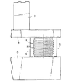
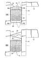
図1〜図8は第1参考例の実施の形態を示すもので、図1は自動車の車体前部の斜視図、図2は図1の2方向拡大矢視図、図3は図1の3−3線拡大断面図、図4は図3の4−4線断面図、図5は図3の5−5線断面図、図6は図3の6−6線断面図、図7は可変衝撃吸収機構の斜視図、図8は衝突時の可変衝撃吸収機構の作用説明図である。 1 to 8 show an embodiment of a first reference example . FIG. 1 is a perspective view of a front portion of a vehicle body of an automobile, FIG. 2 is a two-way enlarged view of FIG. 1, and FIG. FIG. 4 is a sectional view taken along line 4-4 of FIG. 3, FIG. 5 is a sectional view taken along line 5-5 of FIG. 3, FIG. 6 is a sectional view taken along line 6-6 of FIG. FIG. 8 is a perspective view of the variable shock absorbing mechanism, and FIG. 8 is an operation explanatory view of the variable shock absorbing mechanism at the time of collision.
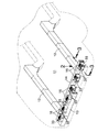
図1に示すように、自動車のエンジンルーム11の左右両側部に車体前後方向に延びる左右一対のフロントサイドフレーム12,12が配置されており、両フロントサイドフレーム12,12の前端間を車体左右方向に接続するクロスメンバ14の前部に、複数個(第1参考例の形態では6個)の可変衝撃吸収機構16…を介してバンパービーム13が支持される。
As shown in FIG. 1, a pair of left and right
6個の可変衝撃吸収機構16の構造は同一であるため、そのうち1個の構造を、図2〜図7に基づいて説明する。
Since the six variable
可変衝撃吸収機構16はフロントエンドプレート17の後面に溶接された第1座屈板18と、リヤエンドプレート19の前面に溶接された第2座屈板20とを備えており、それら第1、第2座屈板18,20は車体前後方向に延びる共通の鉛直面内に配置される。第1座屈板18の後端の上下部にそれぞれ第1ヒンジアーム21,21の基端が溶接され、かつ第2座屈板20の前端の上下部にそれぞれ第2ヒンジアーム22,22の基端が溶接される。第1、第2ヒンジアーム21,21;22,22は、前記鉛直面に対して車幅方向片側に屈曲している。
The variable
第1ヒンジアーム21,21の中間部を上下方向に貫通する第1ヒンジピン23と、第2ヒンジアーム22,22の中間部を上下方向に貫通する第2ヒンジピン24とが、それらの上部、中間部および下部において、それぞれ上部連結部材25、中間部連結部材26および下部連結部材27により回動可能に連結される。
A
上側の第1、第2ヒンジアーム21,22は相互に重なり合うピン孔21a,22a(図6参照)を備えており、そのピン孔21a,22aを第1ロックピン28が摺動自在に貫通する。また下側の第1、第2ヒンジアーム21,22は相互に重なり合うピン孔21a,22aを備えており、そのピン孔21a,22aを第2ロックピン29が摺動自在に貫通する。第1、第2ロックピン28,29の対向部はクランク状に屈曲しており、その対向面にそれぞれラック28a,29aが形成される。何れか一方の座屈板、本参考例の形態では第2座屈板20の一側面に電動モータ30が固定されており、この電動モータ30の出力軸30aに設けたピニオン31が前記第1、第2ロックピン28,29のラック28a,29aに同時に噛合する。
The upper first and
従って、電動モータ30を一方向に回転駆動すると、ピニオン31およびラック28a,29aを介して第1、第2ロックピン28,29が相互に接近する方向に移動し、それら第1、第2ロックピン28,29の先端が第1座屈板18の第1ヒンジアーム21,21のピン孔21a,21aから離脱する。電動モータ30を他方向に回転駆動すると、ピニオン31およびラック28a,29aを介して第1、第2ロックピン28,29が相互に離反する方向に移動し、それら第1、第2ロックピン28,29の先端が第1座屈板18の第1ヒンジアーム21,21のピン孔21a,21aに係合する。
Therefore, when the
前記第1ヒンジアーム21,21、第2ヒンジアーム22,22、第1ヒンジピン23および第2ヒンジピン24はヒンジ機構51を構成する。また前記電動モータ30および第1、第2ロックピン28,29は本発明のロック機構52を構成する。
The
第1、第2座屈板18,20、第1、第2ヒンジアーム21,21;22,22、第1、第2ヒンジピン23,24、上部連結部材25、中間部連結部材26、下部連結部材27、第1、第2ロックピン28,29および電動モータ30は、フロントエンドプレート17およびリヤエンドプレート19を接続する防塵、防水用のベローズ32内に収納される。そしてフロントエンドプレート17およびリヤエンドプレート19が、それぞれバンパービーム13の後面およびクロスメンバ14の前面に固定される。
First and
各々の可変衝撃吸収機構16の左右両側において、バンパービーム13の後面とクロスメンバ14の前面とに一対の衝撃吸収板33,33の前後両端が溶接される。衝撃吸収板33,33は平坦な板状の部材であって、車体前後方向に沿う鉛直面内に配置される。
The front and rear ends of the pair of
可動部分の多い可変衝撃吸収機構16…を介してクロスメンバ14の前部に支持されたバンパービーム13は支持剛性が低下するため、重力で下方に垂れ下がったり、路面から入力される上下方向の荷重で振動して可変衝撃吸収機構16…の耐久性を低下させたりする問題があるが、鉛直面に沿うように配置されているために上下方向の剛性が比較的に高い衝撃吸収板33,33によってクロスメンバ14およびバンパービーム13を連結したことで、クロスメンバ14に対するバンパービーム13の支持剛性を高めて上記問題を解決することができる。
The
次に、上記参考例の形態の作用を説明する。 Next, the operation of the embodiment of the reference example will be described.
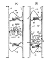
通常時に、バンパービーム13およびクロスメンバ14間に配置された各可変衝撃吸収機構16は、その第1、第2ロックピン28,29が第1、第2ヒンジアーム21,21;22,22のピン孔21a,21a;22a,22aに係合した状態にあり、従って第1、第2座屈板18,20は車体前後方向に沿う鉛直面内で平面状に一体化される。この状態で自車両が他車両に衝突してバンパービーム13に車体前後方向の圧縮荷重が加わると、バンパービーム13およびクロスメンバ14間に挟まれた各可変衝撃吸収機構16が圧縮される。このとき、前記圧縮荷重は第1、第2ロックピン28,29で一体化された第1、第2座屈板18,20の面に沿う方向に入力されるため、図8(A)に示すように、第1、第2座屈板18,20を確実に座屈させて大きな衝突エネルギーを効果的に吸収することができる。
In the normal state, each variable
このとき、各可変衝撃吸収機構16の両側に配置された一対の衝撃吸収板33,33も、その面内に沿う車体前後方向の衝突荷重で効率的に座屈し、衝突エネルギーの吸収に寄与することができる。
At this time, the pair of
一方、車両に搭載したレーダー装置やテレビカメラで衝突の衝撃を小さくする必要がある衝突が予知されると、電動モータ30が作動してピニオン31およびラック28a,29aを介して第1、第2ロックピン28,29が相互に接近する方向に移動し、その先端が第1ヒンジアーム21,21のピン孔21a,21aから離脱することで、第1、第2座屈板18,20はそれぞれ第1、第2ヒンジピン23,24まわりに回動自在な状態になる。しかも第1、第2ヒンジピン23,24の位置は第1、第2座屈板18,20が配置された面から車幅方向片側にオフセットしているため、衝突によって第1、第2座屈板18,20の面に沿う方向の荷重が入力すると、その荷重により第1、第2ヒンジピン23,24まわりにモーメントが発生する。その結果、図8(B)に示すように、第1、第2座屈板18,20は相互に重なり合うように容易に折り畳まれ、バンパービーム13の剛性を小さくして衝突の衝撃を効果的に低減することができる。
On the other hand, when a collision that requires the impact of the collision to be reduced is predicted by a radar device or a television camera mounted on the vehicle, the
このとき、第1座屈板18の第1ヒンジピン23と、第2座屈板20の第2ヒンジピン24とを別個に設けたことにより、第1ヒンジアーム21,21の角部21b,21b(図5参照)および第2ヒンジアーム22,22の角部22b,22b(図5参照)が相互に干渉するのを防止し、第1、第2座屈板18,20を相互に密着するように折り畳んで剛性を小さくすることができる。また同時に衝撃吸収板33,33も座屈するが、これらの衝撃吸収板33,33が座屈する荷重は比較的に小さいため、衝突の衝撃が増加する虞はない。
At this time, by providing the
このように、本参考例の形態によれば、座屈板を第1、第2座屈板18,20に分割して第1、第2ヒンジピン23,24で回動自在に枢支したので、衝突時に第1、第2座屈板18,20を座屈させることなく自由に回動させて折り畳むことで、バンパービーム13を小さい荷重で圧壊して衝突の衝撃を効果的に低減することができる。
Thus, according to the embodiment of the present embodiment, the seat屈板first, first divided into second seat屈板18, since the rotatably supported by the
次に、図9に基づいて第2、第3参考例の形態を説明する。 Next, forms of the second and third reference examples will be described with reference to FIG.
第1参考例の形態の衝撃吸収板33,33は平坦な板状部材であったが、図9(A)に示す第2参考例の形態の衝撃吸収板33,33は、それぞれの前後方向中間部に二つの屈曲部33b,33bを備えている。バンパービーム13に衝突荷重が入力したとき、前記屈曲部33b,33bの作用で衝撃吸収板33,33は一層容易に座屈することができ、衝突の衝撃を更に効果的に低減することができる。図9(B)に示す第3参考例の形態は、一対の平坦な衝撃吸収板33,33を楔状に組み合わせたものである。この配置により、衝撃吸収板33,33の延びる方向と衝突荷重が入力する方向とが傾斜するため、衝撃吸収板33,33の座屈が容易になって衝突の衝撃を更に効果的に低減することができる。
Although the
ところで、バンパービーム13に入力する衝突荷重は基本的に可変衝撃吸収機構16…によって吸収されるため、通常時に衝撃吸収板33,33はバンパービーム13を上下方向に確実に支持する剛性さえ備えていれば良く、衝突の衝撃を小さくすることを考えると前後方向の剛性は低い方が望ましい。
By the way, since the collision load input to the
上記第1〜第3参考例の形態では、衝撃吸収板33,33の両端がバンパービーム13およびクロスメンバ14に溶接により結合されているが、その両端の結合方法には種々の形態が考えられる。
In the first to third reference embodiments, both ends of the
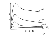
図15(a)は衝撃吸収板33の一端をヒンジ34により左右回動自在に支持し、他端をヒンジ35およびスライダ36により左右回動自在かつ左右摺動自在に支持したものである。図15(b)は衝撃吸収板33の一端を固定し、他端をヒンジ35およびスライダ36により左右回動自在かつ左右摺動自在に支持したものである。図15(c)は衝撃吸収板33の一端および他端を共にヒンジ34,35により左右回動自在支持したものである。図15(d)は衝撃吸収板33の一端を固定し、他端をヒンジ35により左右回動自在支持したものである。図15(d)は衝撃吸収板33の一端および他端を共に固定したものである。
In FIG. 15A, one end of the
このような衝撃吸収板33に前後方向の衝突荷重が入力したとき、前記図15(a)〜(e)の各態様の変位に対する荷重をは、図16に示すように、小さい順に(a)→(b)→(c)→(d)→(e)となる。即ち、一端をヒンジ34により左右回動自在に支持し、他端をヒンジ35およびスライダ36により左右回動自在かつ左右摺動自在に支持した図15(a)の態様が、最も小さい荷重でバンパービーム13を変位させることができ、一端および他端を共に固定した図15(e)の態様が、バンパービーム13を変位させるのに最も大きい荷重が必要であることが分かる。
When a collision load in the front-rear direction is input to such a
従って、図15(a)の態様で衝撃吸収板33をバンパービーム13およびクロスメンバ14に接続することが望ましいが、通常時にバンパービーム13およびクロスメンバ14との接続部の自由度が高過ぎると、バンパービーム13を左右方向に確実に支持することができなくなって振動の問題が発生する。このような問題を解決するのが、以下に説明する本発明の実施の形態である。
Therefore, it is desirable to connect the
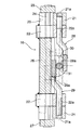
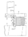
図10〜図12は本発明の実施の形態を示すもので、図10は前記図2に対応する図、図11は図10の11−11線断面図、図12は図11の12−12線断面図である。 10 to 12 show an embodiment of the present invention. FIG. 10 is a view corresponding to FIG. 2, FIG. 11 is a sectional view taken along line 11-11 in FIG. 10, and FIG. It is line sectional drawing.
本実施の形態の衝撃吸収板33,33は平坦な板状部材であって、その前端がヒンジ34,34でバンパービーム13の後面に左右回動自在に支持される。バンパービーム13の上下面から後方に延びる2個のブラケット13a,13aにそれぞれアクチュエータ37,37が設けられており、それらのアクチュエータ37,37により出没するロックピン38,38が衝撃吸収板33の上下縁に設けたロック孔33a,33aに係合する。従って、アクチュエータ37,37のロックピン38,38がロック孔33a,33aに係合した状態で衝撃吸収板33はヒンジ34,34まわりに回動不能にロックされ、アクチュエータ37,37のロックピン38,38がロック孔33a,33aから離脱した状態で衝撃吸収板33はヒンジ34,34まわりに回動可能にアンロックされる。
The
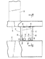
またクロスメンバ14の前面の上下部に左右方向に延びるスリット14a,14aが形成されており、これらのスリット14a,14aにスライダ36,36が左右摺動自在に支持される。そしてスライダ36,36の前面にヒンジ35,35を介して衝撃吸収板33の後端が左右回動自在に支持される。クロスメンバ14の内部に2個のアクチュエータ39,39が設けられており、それらのアクチュエータ39,39により出没するロックピン40,40がスライダ36,36に設けたロック孔36a,36aに係合する。従って、アクチュエータ39,39のロックピン40,40がロック孔36a,36aに係合した状態でスライダ36,36は左右摺動不能にロックされ、アクチュエータ39,39のロックピン40、40がロック孔36a,36aから離脱した状態でスライダ36,36は左右摺動可能にアンロックされる。
Further, slits 14a, 14a extending in the left-right direction are formed at the upper and lower portions of the front surface of the
従って、通常時に衝撃吸収板33の前端のヒンジ34,34の回動をアクチュエータ37,37のピン38,38とピン孔33a,33aとの係合により規制し、衝撃吸収板33の後端のスライダ36,36の摺動をアクチュエータ39,39のピン40,40とピン孔36a,36aとの係合により規制した状態では、衝撃吸収板33の支持態様が図15(d)および図16(d)と同じになり、重力や振動に対してバンパービーム13を確実に支持することができる。そして、この状態で車両が衝突して衝撃吸収板33の前後方向の荷重が入力すると、衝撃吸収板33は確実に座屈して充分な衝撃吸収効果を発揮することができる。
Therefore, the rotation of the
そして衝突の衝撃を小さくする必要がある衝突時には、衝撃吸収板33の前端のヒンジ34,34の回動をアクチュエータ37,37のピン48,48をピン孔33a,33aから離脱させることにより許可し、衝撃吸収板33の後端のスライダ36,36の摺動をアクチュエータ39,39のピン40,40をピン孔36a,36aから離脱させることにより許可するので、衝撃吸収板33の支持態様が図15(a)および図16(a)と同じになり、衝撃吸収板33を容易に左右方向に倒してバンパービーム13の後方への変位を可能にし、衝突の衝撃を大幅に低減することができる。
At the time of a collision that needs to reduce the shock of the collision, the rotation of the
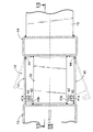
図13および図14は第4参考例の形態を示すもので、図13は前記図2に対応する図(図14の13−13線断面図)、図14は図13の14−14線断面図である。 13 and 14 show the form of the fourth reference example . FIG. 13 is a view corresponding to FIG. 2 (cross-sectional view taken along line 13-13 in FIG. 14), and FIG. 14 is a cross-sectional view taken along line 14-14 in FIG. FIG.
第4参考例の形態は可変衝撃吸収機構16の構造が参考例及び本発明の実施の形態と異なっており、衝撃吸収板33の構造は第1参考例の形態と同じで、その前後両端がそれぞれバンパービーム13およびクロスメンバ14に溶接される。
In the fourth reference example, the structure of the variable
可変衝撃吸収機構16は水平に配置されて車体前後方向に延びる上下一対の座屈板41,41を備えており、各座屈板41の後端はヒンジ44,44でクロスメンバ14に枢支され、前端の左右両側に設けたピン孔41a,41aに、バンパービーム13に設けたブラケット13b,13bに支持したアクチュエータ42,42のロックピン43,43が係脱自在に嵌合する。
The variable
従って、車体変形を小さくする必要がある衝突時にはアクチュエータ42,42のロックピン43,43を座屈板41のピン孔41a,41aに係合させておくことで、座屈板41を衝突の荷重で確実に座屈させて大きな衝突エネルギーを効果的に吸収することができる。一方、衝突の衝撃を小さくする必要がある衝突時にはアクチュエータ42,42のロックピン43,43を座屈板41のピン孔41a,41aから離脱させ、座屈板41の前端をバンパービーム13から切り離すことで、座屈板41の座屈剛性を実質的にゼロにして衝突の衝撃を大幅に低減することができる。
Therefore, when the vehicle body deformation needs to be reduced, the lock pins 43 and 43 of the
このように、本参考例の形態によれば、車体変形を小さくする必要がある衝突時には可変衝撃吸収機構16の座屈剛性を充分に大きくし、衝突の衝撃を小さくする必要がある衝突時には座屈剛性を充分に小さくすることができ、可変衝撃吸収機構16の構造が大幅に簡素化される。尚、衝撃吸収板33,33の作用は上述した第1参考例の形態のものと同じである。
Thus, according to the embodiment of the present reference example , the buckling rigidity of the variable
以上、本発明の実施の形態を説明したが、本発明はその要旨を逸脱しない範囲で種々の設計変更を行うことが可能である。 The embodiments of the present invention have been described above, but various design changes can be made without departing from the scope of the present invention.
例えば、第3参考例の形態では、スライダ36に設けたヒンジ35は左右回動不能にロックできない構造になっているが、それをアクチュエータでロックおよびアンロックできるようにすれば、通常時の衝撃吸収板33の支持態様を図15(e)および図16(e)と同じにして車両との衝突時の衝撃吸収効果を更に高めることができる。
For example, in the form of the third reference example , the
また実施の形態ではレーダー装置やテレビカメラ等で衝突が予知されると、可変衝撃吸収機構16の電動モータ30を作動させているが、衝突に伴う加速度センサの出力や接触センサの出力や車速の情報に基づいて可変衝撃吸収機構16の電動モータ30を作動させても良い。
In the embodiment, when a collision is predicted by a radar device, a TV camera, or the like, the
13 バンパービーム
14 クロスメンバ(車体フレーム)
16 可変衝撃吸収機構
33 衝撃吸収板
34 ヒンジ
37 アクチュエータ
39 アクチュエータ
13
16 variable
Claims (2)
前記衝撃吸収板(33)の前後端部の少なくとも一方は、前記車体フレーム(14)あるいは前記バンパービーム(13)に、鉛直方向の軸線を有するヒンジ(34)で接続され、
前記衝撃吸収板(33)の前記ヒンジ(34)まわりの回動を許可および規制するアクチュエータ(37)を備えることを特徴とする、車両用衝撃吸収装置。 Connect the vehicle frame (14) and the bumper beam (13) and a shock absorption during collision variable variable shock absorbing mechanism (16), the shock absorbing plate disposed in the approximate I vertical plane front and rear ends (33) A vehicle impact absorbing device having a portion connected to the body frame (14) and the bumper beam (13) ,
At least one of the front and rear ends of the shock absorbing plate (33) is connected to the body frame (14) or the bumper beam (13) by a hinge (34) having a vertical axis,
The hinge (34), characterized in that it comprises an actuator (37) for permitting and restricting the rotation around the shock absorbing equipment for a vehicle of the shock absorbing plate (33).
前記衝撃吸収板(33)の前後端部の少なくとも一方は、前記車体フレーム(14)あるいは前記バンパービーム(13)に車幅方向摺動自在に接続され、
前記衝撃吸収板(33)の車幅方向の摺動を許可および規制するアクチュエータ(39)を備えることを特徴とする、車両用衝撃吸収装置。 The vehicle body frame (14) and the bumper beam (13) are connected by a variable shock absorbing mechanism (16) having a variable shock absorbing force at the time of collision, and front and rear end portions of a shock absorbing plate (33) disposed substantially in a vertical plane. A vehicle shock absorber connected to the vehicle body frame (14) and the bumper beam (13),
At least one of the front and rear end portions of the shock absorbing plate (33) is slidably connected to the vehicle body frame (14) or the bumper beam (13) in the vehicle width direction ,
The impact absorption plate, characterized in that it comprises an actuator (39) for permitting and restricting the sliding of the vehicle width direction (33), the shock-absorbing equipment for vehicles.
Priority Applications (1)
| Application Number | Priority Date | Filing Date | Title |
|---|---|---|---|
| JP2006078713A JP4792306B2 (en) | 2006-03-22 | 2006-03-22 | Shock absorber for vehicle |
Applications Claiming Priority (1)
| Application Number | Priority Date | Filing Date | Title |
|---|---|---|---|
| JP2006078713A JP4792306B2 (en) | 2006-03-22 | 2006-03-22 | Shock absorber for vehicle |
Publications (2)
| Publication Number | Publication Date |
|---|---|
| JP2007253700A JP2007253700A (en) | 2007-10-04 |
| JP4792306B2 true JP4792306B2 (en) | 2011-10-12 |
Family
ID=38628385
Family Applications (1)
| Application Number | Title | Priority Date | Filing Date |
|---|---|---|---|
| JP2006078713A Expired - Fee Related JP4792306B2 (en) | 2006-03-22 | 2006-03-22 | Shock absorber for vehicle |
Country Status (1)
| Country | Link |
|---|---|
| JP (1) | JP4792306B2 (en) |
Families Citing this family (2)
| Publication number | Priority date | Publication date | Assignee | Title |
|---|---|---|---|---|
| KR101224576B1 (en) | 2011-01-19 | 2013-01-22 | 에스엘 주식회사 | Front end module for Vehicle |
| JP6245040B2 (en) * | 2014-04-01 | 2017-12-13 | 株式会社豊田中央研究所 | Frame structure and frame device |
Family Cites Families (3)
| Publication number | Priority date | Publication date | Assignee | Title |
|---|---|---|---|---|
| JPH0672757U (en) * | 1993-03-26 | 1994-10-11 | 日産ディーゼル工業株式会社 | Vehicle front bumper |
| JP3516588B2 (en) * | 1998-04-03 | 2004-04-05 | 本田技研工業株式会社 | Body rigidity control device |
| JP4647371B2 (en) * | 2004-05-27 | 2011-03-09 | 本田技研工業株式会社 | Body strength adjustment device |
-
2006
- 2006-03-22 JP JP2006078713A patent/JP4792306B2/en not_active Expired - Fee Related
Also Published As
| Publication number | Publication date |
|---|---|
| JP2007253700A (en) | 2007-10-04 |
Similar Documents
| Publication | Publication Date | Title |
|---|---|---|
| JP4235842B2 (en) | Vehicle hood equipment | |
| US7185934B2 (en) | Vehicle body structure | |
| JP5367152B2 (en) | Vehicle front impact energy absorption structure | |
| JP5967292B2 (en) | Vehicle front structure | |
| JP2001225707A (en) | Shock absorbing mechanism and bumper reinforcement provided with the mechanism | |
| CN109421816A (en) | Body Structure | |
| CN109649501A (en) | Body Structure | |
| JP4539366B2 (en) | Body front structure | |
| JP5914272B2 (en) | Vehicle shock absorption structure | |
| JP4792306B2 (en) | Shock absorber for vehicle | |
| JP2005239092A (en) | Hood structure for automobile | |
| JP4792303B2 (en) | Shock absorber for vehicle | |
| JP5135030B2 (en) | Body front structure | |
| JP2005022598A (en) | Bumper equipment | |
| JP2008213518A (en) | Lamp unit mounting structure | |
| JP4477558B2 (en) | Sheet | |
| JP4851800B2 (en) | Vehicle collision control device | |
| JP2007137224A (en) | Body front structure | |
| JP5013914B2 (en) | Automobile hood shock absorption structure | |
| JP2009248737A (en) | Glove box | |
| JP2002052993A (en) | Front body structure of vehicle | |
| JP4617170B2 (en) | Knee guard structure | |
| JP2008001149A (en) | Vehicle side structure | |
| JP5958790B2 (en) | Impact energy absorption type underlamp protector | |
| JP2016078542A (en) | Vehicle body structure of vehicle rear part |
Legal Events
| Date | Code | Title | Description |
|---|---|---|---|
| A621 | Written request for application examination |
Free format text: JAPANESE INTERMEDIATE CODE: A621 Effective date: 20081127 |
|
| A977 | Report on retrieval |
Free format text: JAPANESE INTERMEDIATE CODE: A971007 Effective date: 20101227 |
|
| A131 | Notification of reasons for refusal |
Free format text: JAPANESE INTERMEDIATE CODE: A131 Effective date: 20101228 |
|
| A521 | Written amendment |
Free format text: JAPANESE INTERMEDIATE CODE: A523 Effective date: 20110223 |
|
| TRDD | Decision of grant or rejection written | ||
| A01 | Written decision to grant a patent or to grant a registration (utility model) |
Free format text: JAPANESE INTERMEDIATE CODE: A01 Effective date: 20110713 |
|
| A01 | Written decision to grant a patent or to grant a registration (utility model) |
Free format text: JAPANESE INTERMEDIATE CODE: A01 |
|
| A61 | First payment of annual fees (during grant procedure) |
Free format text: JAPANESE INTERMEDIATE CODE: A61 Effective date: 20110725 |
|
| FPAY | Renewal fee payment (event date is renewal date of database) |
Free format text: PAYMENT UNTIL: 20140729 Year of fee payment: 3 |
|
| R150 | Certificate of patent or registration of utility model |
Free format text: JAPANESE INTERMEDIATE CODE: R150 |
|
| LAPS | Cancellation because of no payment of annual fees |