JP4792181B2 - Goods storage box - Google Patents
Goods storage box Download PDFInfo
- Publication number
- JP4792181B2 JP4792181B2 JP2001253454A JP2001253454A JP4792181B2 JP 4792181 B2 JP4792181 B2 JP 4792181B2 JP 2001253454 A JP2001253454 A JP 2001253454A JP 2001253454 A JP2001253454 A JP 2001253454A JP 4792181 B2 JP4792181 B2 JP 4792181B2
- Authority
- JP
- Japan
- Prior art keywords
- box
- lid
- contact
- portions
- flange
- Prior art date
- Legal status (The legal status is an assumption and is not a legal conclusion. Google has not performed a legal analysis and makes no representation as to the accuracy of the status listed.)
- Expired - Fee Related
Links
- 229920003002 synthetic resin Polymers 0.000 claims description 6
- 239000000057 synthetic resin Substances 0.000 claims description 6
- 238000005452 bending Methods 0.000 description 1
- 230000000694 effects Effects 0.000 description 1
- 239000000463 material Substances 0.000 description 1
- 230000002093 peripheral effect Effects 0.000 description 1
Images

Landscapes
- Closures For Containers (AREA)
Description
【0001】
【発明の属する技術分野】
本発明は、衣類等の物品を収納する箱体と、この箱体に被せる蓋体とから成る物品収納箱に関するものである。
【0002】
【従来の技術】
この種の物品収納箱の形状や材質は多種多様となっているが、平面長方形で合成樹脂製となっている場合が多い。そして、仕分けの容易さや搬送の容易さ等から、物品収納箱は薄型で積み重ねて使用できるようになっている。
【0003】
一方、マンション等の部屋の専有面積は狭い場合が多いので、その居住者の多くは部屋全体を有効に利用している。例えば、複数の物品収納箱を部屋の壁際に重ねて配置したり、ベッドの下に横に並べて配置したりしている。
【0004】
【発明が解決しようとする課題】
しかしながら、ベッドの下の空間の高さは一様ではないので、物品収納箱の高さが僅かでも高過ぎた場合には、物品収納箱をベッドの下に配置できないことがある。これに対し、物品収納箱の高さがベッドの下に容易に配置し得る高さである場合には、その物品収納箱とベッドとの間の空間が無駄になることが多い。
【0005】
本発明の目的は、上述の課題を解決し、高さを変更可能とすることにより、狭い空間に有効に対応し得る物品収納箱を提供することにある。
【0006】
【課題を解決するための手段】
上記目的を達成するための本発明に係る物品収納箱は、底板と側壁と該側壁の上端縁から側方に突出するフランジを備え物品を収納する合成樹脂製の箱体と、天板と該天板の周縁に設けた外側板と該外側板の内側に設けた当接部を備え前記箱体に被せる合成樹脂製の蓋体とから成る物品収納箱において、前記箱体のフランジには高さ位置が異なる上位段部と下位段部とを有する複数の支持部を設け、前記蓋体の外側板は前記箱体のフランジの外側に嵌合すると共に前記箱体の周辺部を覆い、前記蓋体の当接部は、前記箱体の支持部と同数とし、前記箱体の側壁の内面に接する面部と、前記支持部の上位段部又は下位段部に択一的に上方から当接する突起部とを有し、前記箱体の側壁及びフランジは、前記蓋体の外側板と当接部の面部との間に接して位置し、前記箱体に前記蓋体を第1の方向に向けて被せた際に、前記複数の当接部の突起部は前記複数の支持部の上位段部にそれぞれ当接し、前記箱体に前記蓋体を前記第1の方向とは180度異なる第2の方向に向けて被せた際に、前記複数の当接部の突起部は前記複数の支持部の下位段部にそれぞれ当接するようにしたことを特徴とする。
【0007】
【発明の実施の形態】
本発明を図示の実施の形態に基づいて詳細に説明する。
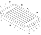
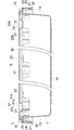
図1は本発明の実施の形態の外観斜視図、図2は図1の中心線Aに沿って切断した拡大短縮断面図である。この実施の形態の物品収納箱は合成樹脂製とし、衣類等の物品を収納し得る平面長方形の箱体1と、この箱体1に被せ得る平面長方形の蓋体2とから構成している。そして、蓋体2の向きを反対にすることにより、蓋体2を箱体1に異なる高さ位置で被せ得るようにしている。なお、物品収納箱の短手方向を前後方向とし、長手方向を左右方向とした場合に、中心線Aは物品収納箱の前後の中心を結ぶ線とし、基線Bは物品収納箱の左右の中心を結ぶ線としている。
【0008】
箱体1は四角筒を形成する側壁11〜14と、これらの側壁11〜14の下端縁側を閉じる底板15と、側壁11〜14の上端縁から外方にそれぞれ突出するフランジ16〜19(フランジ17は図示せず)とを有している。
【0009】
左右のフランジ18、19は、蓋体2を係止するための係止突起20、21を上下方向に間隔をおいてそれぞれ有している。係止突起20、21の前後方向の長さは任意とすることができるが、これらの係止突起20、21は箱体1の方向の基準として利用することができる。
【0010】
例えば、左方のフランジ18の上方の係止突起20は、中心線Aを含むように位置する1つの短い突条とすることができる。また、右方のフランジ19の上方の係止突起20は、中心線Aを挟むように位置する2つの短い突条とすることができる。そして、左右のフランジ18、19の下方の係止突起21は、それぞれ1つの長い突条とすることができる。
【0011】
ここで、蓋体2を異なる高さ位置で支持するために、箱体1の前後のフランジ16、17には例えば3つの支持部22をそれぞれ設け、左右のフランジ18、19には例えば2つの支持部22をそれぞれ設けている。これらの支持部22は中心線Aに関して対称に設けていると共に、基線Bに関して非対称に設けている。
【0012】
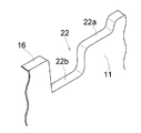
図3は箱体1の例えば前方のフランジ16に設けた1つの支持部22の部分拡大斜視図である。この支持部22には蓋体2を高い位置に支持する上位段部22aと、蓋体2を低い位置に支持する下位段部22bとをそれぞれ設け、その他の支持部22も同様としている。
【0013】
そして、前後のフランジ16、17に沿って位置する3つの支持部22のうち、中央の支持部22の上位段部22aの中心位置は基線Bから右方に距離Cだけ偏心させ、下位段部22bの中心位置は基線Bから左方に距離Cだけ偏心させている。また、両側の支持部22は中央の支持部22に対して等距離で設けている。
【0014】
一方、蓋体2は箱体1のフランジ16〜19の外側に嵌合する外側板31〜34と、これらの外側板31〜34の上端縁側を閉じる天板35とを有している。左右の外側板33、34の内面には、箱体1の係止突起20、21と係合可能な係止突起36をそれぞれ設けている。
【0015】
そして、蓋体2の天板35には、蓋体2を箱体1に被せた際に、箱体1の全ての支持部22の上位段部22a又は下位段部22bにそれぞれ当接する当接部37を設けている。これらの当接部37は中心線Aに関して対称に設けていると共に、基線Bに関して非対称に設けている。
【0016】
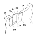
図4にも示すように、当接部37は箱体1の上位段部22a又は下位段部22bの上面に当接するコ字形状の突起部37aと、この突起部37aから側方に延在して箱体1の側壁11〜14の内面に当接する面部37b、37cとを有し、これらの面部37b、37cは蓋体2のがたつきを防止するようになっている。
【0017】
なお、蓋体2の外側板31、32に沿って位置する3つの当接部37のうち、中央の当接部37の突起部37aの中心位置は、基線Bから右方に上述と同様な距離Cだけ偏心させている。また、両側の当接部37は中央の当接部37に対して等距離で設けている。そして、右端の当接部37の面部37cは、右方の外側板34に沿って位置する当接部37との干渉を避けるために幅を狭くしている。
【0018】
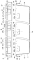
蓋体2を箱体1に高い位置で被せる際には、図5に示すように蓋体2を上述と同様な向きに保持して箱体1に被せる。これにより、蓋体2の全ての当接部37の突起部37aが箱体1の全ての支持部22の上位段部22aにそれぞれ当接すると共に、全ての当接部37の面部37b、37cが箱体1の側壁11〜14の内面にそれぞれ当接する。同時に、蓋体2の係止突起36が箱体1の上方の係止突起20と係合する。なお、蓋体2を取り外す際には、蓋体2の左右の外側板33、34を外方に撓ませながら、蓋体2を上方に持ち上げればよい。
【0019】
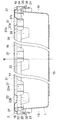
蓋体2を箱体1に低い位置で被せる場合には、図6に示すように蓋体2を水平方向に180度回転して箱体1に被せる。これにより、蓋体2の前後の外側板31、32と左右の外側板33、34がそれぞれ逆方向に位置する。そして図7にも示すように、蓋体2の全ての当接部37の突起部37aが箱体1の全ての支持部22の下位段部22bにそれぞれ当接すると共に、全ての当接部37の面部37b、37cが箱体1の側壁11〜14の内面にそれぞれ当接する。同時に、蓋体2の係止突起36が箱体1の下方の係止突起21と係合する。
【0020】
この実施の形態では、箱体1のフランジ16〜19に支持部22を10個所に設けると共に、蓋体2の天板35に支持部22と同数の当接部37を設け、支持部22には高さ位置の異なる上位段部22aと下位段部22bを設け、箱体1に蓋体2を被せた際に、全ての当接部37が全ての支持部22のうちの同じ高さ位置の上位段部22a又は下位段部22bにそれぞれ当接するようにしたので、蓋体2の高さ位置を変更することが可能となり、狭い空間に有効に対応することができる。
【0021】
以上本発明を好ましい実施の形態について説明したが、本発明は特許請求の範囲を逸脱することなく多様に変形できることは云うまでもない。例えば、箱体1と蓋体2の平面形状を長方形としたが、蓋体2の向きを変えて箱体1に被せ得るのであれば、その他の形状としても支障はない。
【0024】
【発明の効果】
以上説明したように本発明に係る物品収納箱は、箱体の側壁の支持部には高さ位置の異なる2つの段部を設け、箱体に蓋体を被せた際に、蓋体の複数の当接部と上位段部又は下位段部とがそれぞれ当接し、箱体に蓋体を向きを変えて被せた際に、複数の当接部が下位段部又は上位段部とそれぞれ当接するようにしたので、蓋体の向きに応じて蓋体の高さ位置を変更することが可能となり、狭い空間に有効に対応することができる。また、箱体と蓋体との間のがたつきもなく、当接機構が外部から見えることもない。
【図面の簡単な説明】
【図1】本発明の実施の形態の外観斜視図である。
【図2】図1の中心線Aに沿って切断した拡大短縮断面図である。
【図3】支持部の部分拡大斜視図である。
【図4】支持部の上位段部に当接部が当接した状態の部分拡大斜視図である。
【図5】蓋体を箱体に高い位置で被せた状態の拡大短縮断面図である。
【図6】蓋体を箱体に低い位置で被せた状態の拡大短縮断面図である。
【図7】支持部の下位段部に当接部が当接した状態の部分拡大斜視図である。
【符号の説明】
1 箱体
2 蓋体
11〜14 側壁
15 底板
16〜19 フランジ
20、21、36 係止突起
22 支持部
22a 上位段部
22b 下位段部
31〜34 外側板
35 天板
37 当接部
37a 突起部
37b、37c 面部
A 中心線
B 基線[0001]
BACKGROUND OF THE INVENTION
The present invention relates to an article storage box comprising a box for storing articles such as clothes and a lid that covers the box.
[0002]
[Prior art]
There are various shapes and materials of this type of article storage box, but they are often flat rectangular and made of synthetic resin. The article storage boxes are thin and can be used by being stacked because of the ease of sorting and the ease of transport.
[0003]
On the other hand, since the occupied area of a room such as a condominium is often small, many of its residents use the entire room effectively. For example, a plurality of article storage boxes are stacked on the wall of a room or arranged side by side under a bed.
[0004]
[Problems to be solved by the invention]
However, since the height of the space under the bed is not uniform, the article storage box may not be placed under the bed if the height of the article storage box is too high. On the other hand, when the height of the article storage box is such that it can be easily placed under the bed, the space between the article storage box and the bed is often wasted.
[0005]
An object of the present invention is to provide an article storage box that can effectively cope with a narrow space by solving the above-described problems and making the height changeable.
[0006]
[Means for Solving the Problems]
In order to achieve the above object, an article storage box according to the present invention includes a bottom plate, a side wall, a flange that protrudes laterally from the upper edge of the side wall, a box made of synthetic resin that stores articles, a top plate, In an article storage box comprising an outer plate provided at the periphery of the top plate and a synthetic resin lid that is provided on the inner side of the outer plate and covers the box, the flange of the box has a height A plurality of support portions having upper and lower step portions having different positions are provided, and the outer plate of the lid body fits outside the flange of the box body and covers the peripheral portion of the box body, The number of the contact portions of the lid is the same as the number of support portions of the box, and alternatively the surface portion that contacts the inner surface of the side wall of the box and the upper step portion or the lower step portion of the support portion are alternatively contacted from above. A side wall and a flange of the box body between the outer plate of the lid body and the surface portion of the contact portion. And is located, when the lid to the box body is covered toward the first direction, the protrusion of the plurality of abutment abut respectively upper stepped portion of the plurality of support portions, wherein When the lid is put on the box in a second direction that is 180 degrees different from the first direction, the protrusions of the plurality of abutting portions are respectively disposed on lower step portions of the plurality of support portions. It is characterized by being in contact.
[0007]
DETAILED DESCRIPTION OF THE INVENTION
The present invention will be described in detail based on the illustrated embodiment.
FIG. 1 is an external perspective view of an embodiment of the present invention, and FIG. 2 is an enlarged shortened sectional view cut along a center line A of FIG. The article storage box of this embodiment is made of synthetic resin, and includes a flat
[0008]
The
[0009]
The left and
[0010]
For example, the
[0011]
Here, in order to support the
[0012]
FIG. 3 is a partially enlarged perspective view of one
[0013]
Of the three
[0014]
On the other hand, the
[0015]
Then, the
[0016]
As shown in FIG. 4, the
[0017]
Of the three
[0018]
When the
[0019]
When the
[0020]
In this embodiment, the
[0021]
Although the present invention has been described with reference to the preferred embodiment, it is needless to say that the present invention can be variously modified without departing from the scope of the claims. For example, the planar shape of the
[0024]
【The invention's effect】
As described above, the article storage box according to the present invention is provided with two step portions having different height positions on the support portion of the side wall of the box, and when the box is covered with the lid, When the plurality of abutting portions and the upper step portion or the lower step portion are in contact with each other, and the lid is placed on the box with the direction changed, the plurality of abutting portions respectively contact the lower step portion or the upper step portion. Since it contacts, it becomes possible to change the height position of a cover body according to the direction of a cover body, and can respond | correspond effectively to a narrow space. Further, there is no rattling between the box and the lid, and the contact mechanism is not visible from the outside.
[Brief description of the drawings]
FIG. 1 is an external perspective view of an embodiment of the present invention.
2 is an enlarged shortened cross-sectional view taken along the center line A of FIG.
FIG. 3 is a partially enlarged perspective view of a support portion.
FIG. 4 is a partially enlarged perspective view of a state in which a contact portion is in contact with an upper step portion of a support portion.
FIG. 5 is an enlarged and shortened cross-sectional view of a state where a lid is put on a box at a high position.
FIG. 6 is an enlarged shortened cross-sectional view of a state where a lid is put on a box at a low position.
FIG. 7 is a partially enlarged perspective view showing a state in which the contact portion is in contact with the lower step portion of the support portion.
[Explanation of symbols]
DESCRIPTION OF
31-34
Claims (3)
前記箱体のフランジには高さ位置が異なる上位段部と下位段部とを有する複数の支持部を設け、
前記蓋体の外側板は前記箱体のフランジの外側に嵌合すると共に前記箱体の周辺部を覆い、
前記蓋体の当接部は、前記箱体の支持部と同数とし、前記箱体の側壁の内面に接する面部と、前記支持部の上位段部又は下位段部に択一的に上方から当接する突起部とを有し、
前記箱体の側壁及びフランジは、前記蓋体の外側板と当接部の面部との間に接して位置し、
前記箱体に前記蓋体を第1の方向に向けて被せた際に、前記複数の当接部の突起部は前記複数の支持部の上位段部にそれぞれ当接し、
前記箱体に前記蓋体を前記第1の方向とは180度異なる第2の方向に向けて被せた際に、前記複数の当接部の突起部は前記複数の支持部の下位段部にそれぞれ当接するようにしたことを特徴とする物品収納箱。A synthetic resin box having a bottom plate, a side wall, and a flange projecting laterally from the upper edge of the side wall, housing the article, a top plate, an outer plate provided on the periphery of the top plate, and an inner side of the outer plate In the article storage box comprising a cover made of synthetic resin and having a contact portion provided , and covering the box body,
The flange of the box is provided with a plurality of support portions having upper and lower steps different in height position,
The outer plate of the lid is fitted to the outside of the flange of the box and covers the periphery of the box,
The number of contact portions of the lid is the same as the number of support portions of the box, and alternatively, the surface portion that contacts the inner surface of the side wall of the box and the upper step portion or the lower step portion of the support portion are selectively applied from above. And a protruding portion that contacts
The side wall and the flange of the box are positioned between the outer plate of the lid and the surface portion of the contact portion,
When the lid is put on the box body in the first direction, the protrusions of the plurality of contact portions are in contact with the upper stage portions of the plurality of support portions , respectively.
When the lid is put on the box in a second direction that is 180 degrees different from the first direction, the protrusions of the plurality of abutting portions are arranged at lower steps of the plurality of support portions. An article storage box characterized by being in contact with each other.
Priority Applications (1)
| Application Number | Priority Date | Filing Date | Title |
|---|---|---|---|
| JP2001253454A JP4792181B2 (en) | 2001-08-23 | 2001-08-23 | Goods storage box |
Applications Claiming Priority (1)
| Application Number | Priority Date | Filing Date | Title |
|---|---|---|---|
| JP2001253454A JP4792181B2 (en) | 2001-08-23 | 2001-08-23 | Goods storage box |
Publications (2)
| Publication Number | Publication Date |
|---|---|
| JP2003063534A JP2003063534A (en) | 2003-03-05 |
| JP4792181B2 true JP4792181B2 (en) | 2011-10-12 |
Family
ID=19081777
Family Applications (1)
| Application Number | Title | Priority Date | Filing Date |
|---|---|---|---|
| JP2001253454A Expired - Fee Related JP4792181B2 (en) | 2001-08-23 | 2001-08-23 | Goods storage box |
Country Status (1)
| Country | Link |
|---|---|
| JP (1) | JP4792181B2 (en) |
Family Cites Families (3)
| Publication number | Priority date | Publication date | Assignee | Title |
|---|---|---|---|---|
| JPH0610136U (en) * | 1991-12-09 | 1994-02-08 | 天昇電気工業株式会社 | Costume case |
| JPH10175636A (en) * | 1996-10-14 | 1998-06-30 | Sekisui Chem Co Ltd | container |
| JP3451051B2 (en) * | 2000-01-31 | 2003-09-29 | 株式会社ニトムズ | Food storage containers |
-
2001
- 2001-08-23 JP JP2001253454A patent/JP4792181B2/en not_active Expired - Fee Related
Also Published As
| Publication number | Publication date |
|---|---|
| JP2003063534A (en) | 2003-03-05 |
Similar Documents
| Publication | Publication Date | Title |
|---|---|---|
| JPH02504501A (en) | container adapter | |
| JP4792181B2 (en) | Goods storage box | |
| JP2000168779A (en) | Storing box | |
| JP7199083B2 (en) | packaging container | |
| JPH0635943Y2 (en) | Rectangular container | |
| JP3677440B2 (en) | Folding container | |
| JP4535593B2 (en) | Storage case | |
| JP4303561B2 (en) | Dunedage stacking system and cover member for Dunedge stacking system | |
| JP4538172B2 (en) | Resin storage case | |
| JP3006787U (en) | Storage case | |
| JP3025667U (en) | CD case | |
| JP3252873B2 (en) | Box type container | |
| JP4089805B2 (en) | Container with lid | |
| JP3028647U (en) | Bento container | |
| JP3842638B2 (en) | Folding container | |
| JP3243343B2 (en) | Container with partition | |
| KR200417982Y1 (en) | Goods packaging boxes | |
| JPH09165042A (en) | Containing case | |
| JP3261258B2 (en) | Transport container | |
| JPH074341U (en) | Container | |
| JPH068050Y2 (en) | Package | |
| JP4480288B2 (en) | Large container | |
| JPH063838U (en) | Transport container | |
| JP3059441U (en) | Multi-stage storage case | |
| JPH0239933Y2 (en) |
Legal Events
| Date | Code | Title | Description |
|---|---|---|---|
| A621 | Written request for application examination |
Free format text: JAPANESE INTERMEDIATE CODE: A621 Effective date: 20080424 |
|
| A977 | Report on retrieval |
Free format text: JAPANESE INTERMEDIATE CODE: A971007 Effective date: 20101018 |
|
| A131 | Notification of reasons for refusal |
Free format text: JAPANESE INTERMEDIATE CODE: A131 Effective date: 20101109 |
|
| A521 | Written amendment |
Free format text: JAPANESE INTERMEDIATE CODE: A523 Effective date: 20101224 |
|
| TRDD | Decision of grant or rejection written | ||
| A01 | Written decision to grant a patent or to grant a registration (utility model) |
Free format text: JAPANESE INTERMEDIATE CODE: A01 Effective date: 20110705 |
|
| A01 | Written decision to grant a patent or to grant a registration (utility model) |
Free format text: JAPANESE INTERMEDIATE CODE: A01 |
|
| A61 | First payment of annual fees (during grant procedure) |
Free format text: JAPANESE INTERMEDIATE CODE: A61 Effective date: 20110725 |
|
| FPAY | Renewal fee payment (event date is renewal date of database) |
Free format text: PAYMENT UNTIL: 20140729 Year of fee payment: 3 |
|
| R150 | Certificate of patent or registration of utility model |
Free format text: JAPANESE INTERMEDIATE CODE: R150 |
|
| R250 | Receipt of annual fees |
Free format text: JAPANESE INTERMEDIATE CODE: R250 |
|
| R250 | Receipt of annual fees |
Free format text: JAPANESE INTERMEDIATE CODE: R250 |
|
| LAPS | Cancellation because of no payment of annual fees |