JP4792179B2 - Vehicle door - Google Patents
Vehicle door Download PDFInfo
- Publication number
- JP4792179B2 JP4792179B2 JP2001230789A JP2001230789A JP4792179B2 JP 4792179 B2 JP4792179 B2 JP 4792179B2 JP 2001230789 A JP2001230789 A JP 2001230789A JP 2001230789 A JP2001230789 A JP 2001230789A JP 4792179 B2 JP4792179 B2 JP 4792179B2
- Authority
- JP
- Japan
- Prior art keywords
- inner panel
- wiper motor
- mounting bracket
- vehicle
- panel
- Prior art date
- Legal status (The legal status is an assumption and is not a legal conclusion. Google has not performed a legal analysis and makes no representation as to the accuracy of the status listed.)
- Expired - Fee Related
Links
Images

Landscapes
- Body Structure For Vehicles (AREA)
Description
【0001】
【発明の属する技術分野】
本発明は、車両用ドアに係り、例えば、四輪車両のバックドアであるテールゲートに利用できるものである。
【0002】
【背景技術】
特開平10−100684号には、四輪車両のバックドアであるテールゲートの補強構造が示されている。この補強構造は、車両外側のアウターパネルに接合される車両内側のインナーパネルに車両外側への立ち上げによる立上部を設けるとともに、インナーパネルの車両外側の面に補強プレートを結合し、この補強プレートにも車両外側へ立ち上がった立上部を設け、この立上部とインナーパネルの立上部とを接合している。
【0003】
これによると、補強プレートによってインナーパネルが補強されるとともに、補強プレートの立上部とインナーパネルの立上部との接合により、インナーパネルの強度、延いてはテールゲートの強度を向上させることができる。
【0004】
【発明が解決しようとする課題】
しかし、テールゲートには、ドア用部品であるドアロックやアウターハンドル等が取り付けられ、ワイパー装置を備えるタイプのテールゲートの場合には、これらのドア用部品の他に、ワイパーモータも取り付けられ、そして、ワイパーモータ等のドア用部品をインナーパネルに取り付けるためのブラケットもインナーパネルに結合される。
【0005】
このため、インナーパネルに補強プレートを結合するようにした上記従来技術では、インナーパネルに、上記各種のドア用部品と、これらのドア用部品のための取付用ブラケットと、補強プレートとが取り付けられることになる。これによると、車両の燃費改善のために求められるテールゲート全体重量の軽量化の実現には一定の限界があり、テールゲート全体重量を一層軽量化できる工夫が求められる。
【0006】
本発明の目的は、大きな強度を確保しながら、ドア重量の一層の軽量化を図ることができる車両用ドアを提供するところにある。
【0007】
【課題を解決するための手段】
本発明に係る車両用ドアは、車両外側のアウターパネルと、このアウターパネルに接合される車両内側のインナーパネルとを含んで形成され、このインナーパネルに車両外側への立ち上げで形成された立上部が設けられている車両用ドアにおいて、前記インナーパネルにドア用部品取付用ブラケットが結合され、このブラケットに車両外側へ立ち上った立上部が設けられているとともに、この立上部と、前記インナーパネルの立上部とが接合されていることを特徴とするものである。
【0008】
この車両用ドアによると、インナーパネルにドア用部品取付用ブラケットが結合されるとともに、、このブラケットに車両外側へ立ち上った立上部が設けられ、この立上部と、インナーパネルの立上部とが接合されているため、インナーパネルの強度は向上し、車両用ドアの強度も向上することになる。
【0009】
特に、インナーパネルの立上部と接合される立上部が設けられている部材は、インナーパネルに取り付けられるドア用部品のための取付用ブラケットであるため、車両用ドアに設けなければならない部材が活用されることになる。このため、インナーパネルの立上部と接合される立上部を設けるための特別の部材をインナーパネルに結合する必要はなく、これにより、インナーパネルの重量は重くならず、車両用ドアの全体重量を従来技術よりも軽量化できることになる。
【0010】
本発明において、インナーパネルの立上部を第1立上部とした場合、インナーパネルに第2立上部も設け、この第2立上部の延設方向を第1立上部の延設方向と直交又は略直交する方向とすることが好ましい。
【0011】
これによると、インナーパネルの強度は第2立上部でさらに補強されることになるとともに、第1立上部の延設方向と第2立上部の延設方向は互いに直交又は略直交することになるため、各方向の荷重に対するインナーパネルの強度が確保されることになる。
【0012】
また、第1立上部と第2立上部のそれぞれを複数とすると、これらの立上部はインナーパネルに井桁形状をなして形成されることになり、この結果、インナーパネルの全体強度は一層大きくなり、車両用ドアの全体強度も充分大きくなる。
【0013】
さらに、第1立上部と第2立上部をインナーパネルに形成される同じ開口部の縁部の立ち上げで形成するとともに、この開口部の面積を第1立上部と第2立上部の合計面積よりも大きくしてもよい。
【0014】
これによると、第1立上部と第2立上部をインナーパネルに形成される同じ開口部の縁部を利用して設けることができるとともに、開口部の面積は第1立上部と第2立上部の合計面積よりも大きいため、その分だけインナーパネルの重量の一層の軽量化を図ることができ、車両用ドアの全体重量を一層軽くできる。
【0015】
なお、第1立上部と第2立上部は、インナーパネルにそれぞれ別に形成される開口部の縁部の立ち上げで形成してもよい。
【0016】
また、第1立上部と第2立上部はその立ち上がり方向に直線的に延びるものでもよく、立ち上がり方向の途中に1個又は複数個の屈曲部があるものでもよい。
【0017】
また、以上において、板金製であるインナーパネルは一枚のブランク材で形成してもよく、あるいは、板厚が異なるブランク材を含む複数のブランク材の接合によるテーラードブランクで形成してもよい。
【0018】
後者によると、インナーパネルの重量を軽量化しつつ、インナーパネルの特定箇所の強度を大きくできるという効果を得られる。また、インナーパネルの材料となるブランク材の材料歩留まりを向上させることができる。
【0019】
このようにインナーパネルをテーラドブランクで形成する場合には、テーラードブランクを形成している複数のブランク材のうち、前記ドア用部品取付用ブラケットが結合されるブランク材の板厚を、このブランク材の周囲のブランク材の板厚よりも大きくしてもよい。
【0020】
これによると、インナーパネルのうち、ドア用部品取付用ブラケットが配置される箇所についての大きな強度がこのブラケットと板厚の大きいブランク材とによって確保されることになり、この箇所に重量物であるドア用部品でも充分取り付けることができる。
【0021】
以上の本発明に係る車両用ドアは、テールゲートでもよく、サイドドアでもよい。また、本発明に係る車両用ドアがテールゲートである場合には、このテールゲートは、上部のヒンジで車体に連結され、開閉方向が上下方向となっているものでもよく、側部のヒンジで車体に連結され、開閉方向が左右方向となっているものでもよい。また、本発明に係る車両用ドアがサイドドアである場合には、このサイドドアは、ヒンジで車両に連結され、このヒンジを中心に開閉する開き戸タイプのものでもよく、車体にスライド自在に配置され、スライドによって開閉するタイプのものでもよい。
【0022】
本発明に係る車両用ドアにおける前記ドア用部品取付用ブラケットは、車両に取り付けられるアウターハンドル、ウォッシャノズル、キーシリンダ等の任意なドア用部品をインナーパネルに取り付けるためのものでよいが、本発明に係る車両用ドアがテールゲートである場合における前記ドア用部品取付用ブラケットの一例は、ワイパー装置付きテールゲートに配設されるワイパーモータをインナーパネルに取り付けるためのブラケットである。
【0023】
このようにドア用部品取付用ブラケットをワイパーモータ取付用ブラケットとすると、ワイパーモータは他のドア用部品よりも一般的に大型でしかも重いため、ワイパーモータ取付用ブラケットも自ずと大きなものとなる。このため、このブラケット自体及びこのブラケットの前記立上部で補強されるインナーパネルの強度を充分大きくできるという効果を得られる。
【0024】
【発明の実施の形態】
以下に本発明の一実施形態を図面に基づいて説明する。本実施形態に係る車両用ドアは四輪車両のテールゲートであり、図1に示すように、このテールゲート1は、四輪車両の車体2の後部に上部のヒンジ3で連結され、これらのヒンジ3を中心に上下に開閉自在である。また、テールゲート1は、窓孔1Aに嵌め込まれたガラス4を清掃するワイパー装置5を備えており、このワイパー装置5のワイパーアーム5Aの基端部は左右に一定角度揺動する揺動軸5Bに結合されている。
【0025】
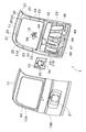
図2はテールゲート1の分解斜視図であり、テールゲート1は車両外側の板金製のアウターパネル10と、車両内側の板金製のインナーパネル11とを主要な部材として形成され、これ以外にテールゲート1を形成する部材の一つには、インナーパネル11よりも車両内側においてインナーパネル11の略下半分に結合される図示しない合成樹脂製のライニングがある。ワイパー装置5の前記揺動軸5Aを備えているワイパーモータ12は、テールゲート1に取り付けられるドア用部品の一つであり、このワイパーモータ12はインナーパネル11に板金製のワイパーモータ取付用ブラケット13で取り付けられる。
【0026】
テールゲート1に取り付けられる他のドア用部品には、図1で示されているアウターハンドル6やウォッシャノズル7、さらには図面では示されていないドアロック等があるが、これらは図2では省略され、ドアロックをインナーパネル11に取り付けるためのブラケットも省略されている。
【0027】
図2において、アウターパネル10は、窓孔20が形成された上部の窓枠部10Aと、図1で示すライセンスプレート8が取り付けられる窪み部21が形成された下部のパネル本体部10Bとからなる。全体形状及び大きさがアウターパネル10と対応しているインナーパネル11は、窓孔22が形成された上部の窓枠部11Aと、アウターパネル10のパネル本体部10Bと対応する下部のパネル本体部11Bとからなる。
【0028】
また、インナーパネル11は、接合部23で接合された合計7個の構成要素30〜36からなり、すなわち、インナーパネル11はそれぞれの構成要素30〜36ごとに用意された合計7枚の鋼鈑製のブランク材によるテーラードブランクから形成されている。これらのブランク材のうち、図1のヒンジ3の結合箇所に配置されている構成要素31,32のブランク材の厚さが最も大きく、これは例えば1.4mmであり、インナーパネル11の窓枠11Aとパネル本体部11Bとに跨る箇所に配置されている構成要素35のブランク材の厚さが次ぎに大きく、これは例えば0.7mmであり、残りの構成要素30,33,34,36のブランク材の厚さが最も小さく、その厚さは構成要素30,33,34,36について同じであって、これは例えば0,6mmである。
【0029】
したがって、ヒンジ3を介して図1の車体2と連結される箇所の強度は、ブランク材の厚さを大きくすることにより確保されている。
【0030】
また、インナーパネル11には、断面がハット形状であって車両外側に向かって開口しているハット形状部37が形成されており、このハット形状部37は、幅及び深さは変化しているが、インナーパネル11の全周に亘って連続して形成されている。テールゲート1を製造するために、インナーパネル11とアウターパネル10とが接着とヘミング加工あるいはヘミング加工とスポット溶接等で接合されることにより、インナーパネル11のハット形状部37の車両外側に向かって開口した開口部がアウターパネル10で塞がれ、これにより、断面がボックス形状となったボックス部がテールゲート1の全周に亘って連続して形成されるようになっている。
【0031】
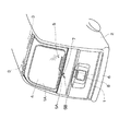
図3は、インナーパネル11の下部のパネル本体部11Bについての拡大斜視図である。前述のテーラドブランクをプレス成形することにより形成されるインナーパネル11には、窓孔22の下部において左右に延びる溝部40が形成され、この溝部40の下部には車両外側へ高くなった段丘部41が設けられ、さらにこの段丘部41の下部には車両外側へ隆起した隆起部42が形成されている。この隆起部42の下部には、ドアロックを配置するための凹部43が設けられている。
【0032】
段丘部41には、ワイパーモータ12をインナーパネル11の車両内側から挿入して車両外側へ露出させるためのワイパーモータ用挿入孔44が形成され、この孔44の外周部には、孔44の外周縁部の立ち上げによって設けられた壁部45が形成されている。また、隆起部42には、略縦長四角形となった4個の開口部46〜49が左右方向に並設され、これらの開口部46〜49の外周部にも、開口部46〜49の外周縁部の立ち上げによる壁部50〜53が形成されている。
【0033】
これらの壁部50〜53のうち、それぞれの開口部46〜49の左右辺部は第1立上部50A,50B,51A,51B,52A,52B,53A,53Bとなっており、上下辺部は第2立上部50C,50D,51C,51D,52C,52D,53C,53Dとなっている。また、第1立上部50A,50B,51A,51B,52A,52B,53A,53Bのうち、第1立上部50B,51A,51B,52Aの立上量は大きく、その先端には開口部46〜48の内側へ屈曲したリップ50F,51E,51F,52Eが形成されている。
【0034】
第1立上部50A,50B,51A,51B,52A,52B,53A,53Bの延設方向は、インナーパネル11の上下方向又は略上下方向であり、第2立上部50C,50D,51C,51D,52C,52D,53C,53Dの延設方向は、インナーパネル11の左右方向又は略左右方向である。このため、第1立上部50A,50B,51A,51B,52A,52B,53A,53Bと第2立上部50C,50D,51C,51D,52C,52D,53C,53Dは、互いに直交又は略直交する方向に延びている。
【0035】
また、第1立上部50A,50B,51A,51B,52A,52B,53A,53Bと第2立上部50C,50D,51C,51D,52C,52D,53C,53Dは、それぞれの開口部46〜49をインナーパネル11にプレス成形で形成する際に形成され、開口部46についてのリップ50Fを含む立上部50A〜Dの合計面積は開口部46の面積よりも小さく、以下同じく、開口部47についてのリップ51E,51Fを含む立上部51A〜Dの合計面積は開口部47の面積よりも小さく、開口部48についてのリップ52Eを含む立上部52A〜Dの合計面積は開口部48の面積よりも小さく、開口部49についての立上部53A〜Dの合計面積は開口部46の面積よりも小さい。
【0036】
したがって、それぞれの開口部46〜49は、それぞれの開口部46〜49における立上部の合計面積よりも大きな面積となっている。
【0037】
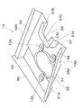
図4は、ワイパーモータ取付用ブラケット13の全体を示す斜視図である。板金プレス製品であるこのブラケット13は、上部立上部60と、この上部立上部60の左右端部から下方へ略平行に延びる側部立上部61,62とを有し、これらの側部立上部61,62の先端には外側へ屈曲したリップ61A,62Aが形成されている。また、上部立上部60と左右の側部立上部61,62とで囲まれる内部は、上部立上部60側の第1底部63と、第1底部63よりも高い第2底部64とになっており、第2底部64に、図3で示したインナーパネル11のワイパーモータ用挿入孔44と対応する孔65が設けられ、この孔65の外周縁部は立ち上がった壁部65Aとなっている。そして、第1底部63と第2底部64には、ワイパーモータ12の結合用座凹部13Aが設けられている。第2底部64の下端の左右中央部には上方へ切り込まれた凹欠部66が設けられ、この凹欠部66の外周縁部は立ち上がった壁部67となっている。この壁部67は、左右の側部立上部61,62と平行又は略平行となった左右の縦立上部67A,67Bと、これらの縦立上部67A,67Bの上部間を繋ぐ横立上部67Cとからなり、これらの立上部67A〜Cの先端には、凹欠部66の内側へ屈曲したリップ67Dが形成されている。
【0038】
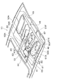
図5は、インナーパネル11の車両外側の面にワイパーモータ取付用ブラケット13を当て、インナーパネル11にブラケット13を結合したときを示す。インナーパネル11の車両外側の面にブラケット13を当てるときは、図5で示されているように、インナーパネル11の孔44とブラケット13の孔65とを、孔44の壁部45を孔65の壁部65Aの内側に入れて一致させ、インナーパネル11の溝部40にブラケット13の第1底部63を嵌め込み、インナーパネル11の段丘部41と隆起部42とにブラケット13の第2底部64を跨らせるとともに、インナーパネル11の第1立上部50B,51A,51B,52Aとブラケット13の側部立上部61、縦立上部67A,67B、側部立上部62とを互いに隣接させ、第1立上部50B,51A,51B,52Aのリップ50F,51E,51F,52Eに側部立上部61のリップ61A、縦立上部67A,67Bのリップ67D、側部立上部62のリップ62Aを重ねる。
【0039】
この後、インナーパネル11とブラケット13とを複数箇所でスポット溶接する。これにより、インナーパネル11とブラケット13は結合一体化されるとともに、インナーパネル11の第1立上部50B,51A,51B,52Aとブラケット13の側部立上部61、縦立上部67A,67B、側部立上部62とが互いに接合され、第1立上部50B,51A,51B,52Aのリップ50F,51E,51F,52Eと側部立上部61のリップ61A、縦立上部67A,67Bのリップ67D、側部立上部62のリップ62Aも互いに接合される。
【0040】
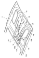
図6は、インナーパネル11にブラケット13を介してワイパーモータ12を取り付けるときを示す。このワイパーモータ取付作業は、インナーパネル11の孔44とブラケット13の孔65とにワイパーモータ12を車両内側から挿入し、ワイパーモータ12の大部分をブラケット1の車両外側へ露出させるとともに、ワイパーモータ12に設けられているブラケット部12Aに配置したボルト12Bを、インナーパネル11の孔44の周囲に設けたボルト挿通孔と、ブラケット13のワイパーモータ結合用座凹部13Aに設けたボルト挿通孔とに挿通し、それぞれのボルト12Bの先端にナットを螺締することにより行われる。
【0041】
また、ワイパーモータ12以外の前述したドアロック等のドア用部品をインナーパネル11に取り付ける作業や、ハーネスを配線する作業も行う。
【0042】
そして、インナーパネル11とアウターパネル10とを前述のヘミング加工等で接合一体化する作業が行われ、また、前述したライニングをインナーパネル11の下部のパネル本体部11Bにおける車両内側の面に取り付ける作業も行われる。インナーパネル11とアウターパネル10とを接合一体化する作業時において、インナーパネル11の立上量が大きい第1立上部50B,51A,51B,52Aによってテールゲート1の所定の厚さが確保される。
【0043】
なお、ワイパーモータ12のボルト12Bに螺締される前記ナットを予めワイパーモータ結合用座凹部13Aに結合しておくことにより、インナーパネル11とアウターパネル10とを接合一体化した後に、ワイパーモータ12のブラケット部12Aに挿入したボルト12Bを前記ボルト挿通孔に挿通してナットに螺入することにより、ワイパーモータ12をブラケット13を介してインナーパネル11に取り付ける作業を行ってもよい。このような作業順序でワイパーモータ取付作業を行う場合には、ワイパーモータ12以外のドア用部品をインナーパネル11に取り付ける作業やハーネス配線作業も、開口部46〜49を利用することにより、インナーパネル11とアウターパネル10を接合一体化した後に行ってもよい。
【0044】
これによると、インナーパネル11とアウターパネル10の全体をこれらを接合一体化した後に塗装処理できるという利点を得られる。
【0045】
以上説明した実施形態によると、インナーパネル11にワイパーモータ取付用ブラケット13が結合され、このブラケット13に車両外側へ立ち上った立上部61,62,67A,67Bが設けられ、これらの立上部61,62,67A,67Bとインナーパネル11の第1立上部50B,51A,51B,52Aとが接合されるため、インナーパネル11の強度は向上し、テールゲート1の強度も向上することになる。
【0046】
特に、インナーパネル11の第1立上部50B,51A,51B,52Aと接合される立上部61,62,67A,67Bが設けられている部材は、インナーパネル11に取り付けられるワイパーモータ12のための取付用ブラケット13であるため、テールゲート1に設けなければならない部材を活用してインナーパネル11の強度を大きくできることになり、このため、インナーパネル11の立上部と接合される立上部を設けるために特別の部材をインナーパネルに結合する必要はなく、これにより、インナーパネル11の重量は重くならず、テールゲート1の全体重量を従来技術よりも軽量化できることになる。
【0047】
また、ワイパーモータ12はインナーパネル11に取り付けられるドア用部品のなかで大型のものであり、このため、ワイパーモータ取付用ブラケット13は比較的大きな面積を有するため、この大面積のブラケット13によってインナーパネル11の補強強度を充分大きくできる。
【0048】
また、インナーパネル11には、第1立上部50A,50B,51A,51B,52A,52B,53A,53Bと、これらの第1立上部50A,50B,51A,51B,52A,52B,53A,53Bと直交又は略直交する方向に延設された第2立上部50C,50D,51C,51D,52C,52D,53C,53Dとが設けられているため、インナーパネル11はこれらの第1及び第2立上部によって補強されることになり、各方向の荷重に対しての強度をインナーパネルは備えることになる。
【0049】
また、第1立上部50A,50B,51A,51B,52A,52B,53A,53Bと第2立上部50C,50D,51C,51D,52C,52D,53C,53Dのそれぞれは複数個あるため、これらの立上部はインナーパネル11に井桁形状をなして形成されることになり、この結果、インナーパネル11の全体強度は一層大きくなり、テールゲート1の全体強度も充分大きくなる。
【0050】
また、ワイパーモータ取付用ブラケット13にも、立上部61,62,67A,67Bと直交又は略直交する方向に延設された上部立上部60、横立上部67Cがあるため、これらの立上部60、67Cもインナーパネル11の強度向上に貢献する。
【0051】
さらに、インナーパネル11には、インナーパネル11の全周に亘って連続しているハット形状部37が設けられ、このハット形状部37は、インナーパネル11とアウターパネル10とを接合一体化すると、テールゲート1の全周に亘って連続するボックス形状部となるため、テールゲート1の全体強度はこのボックス形状部によっても向上する。
【0052】
また、インナーパネル11の第1立上部50A,50Bと第2立上部50C,50Dは同じ開口部46の縁部の立ち上げで、第1立上部51A,51Bと第2立上部51C,51Dは同じ開口部47の縁部の立ち上げで、第1立上部52A,52Bと第2立上部52C,52Dは同じ開口部48の立ち上げで、第1立上部53A,53Bと第2立上部53C,53Dは同じ開口部49の縁部の立ち上げでそれぞれ形成されているため、第1立上部と第2立上部を同じ開口部の縁部を利用して設けることができるとともに、同じ開口部の縁部の立ち上げで形成されたリップを含む第1立上部と第2立上部の合計面積は、その開口部の面積よりも小さく、開口部の面積が第1立上部と第2立上部の合計面積よりも大きくなっている分だけ、インナーパネル11の全体重量を軽量化することができる。
【0053】
また、インナーパネル11は合計7枚のブランク材の接合によるテーラードブランクで形成され、これらのブランク材のうち、図2で示したワイパーモータ取付用ブラケット13が結合される構成要素35のブランク材は、この構成要素35の周囲の構成要素33,34,36のブランク材よりも板厚が大きいため、インナーパネル11の全体重量の軽量化を図りながら、重量物であるワイパーモータ12が取り付けられる構成要素35の箇所の強度を大きくできる。
【0054】
また、図1で示したヒンジ3が結合される構成要素31,32の箇所のブランク材の板厚も大きいため、車体2にテールゲート1を連結するための強度も大きくできる。
【0055】
また、インナーパネル11を複数枚のブランク材の接合によるテーラードブランクで形成しているため、接合前のそれぞれのブランク材の大きさ及び形状を構成要素30〜36と対応したものとしておくことにより、インナーパネルを一枚の大面積のブランク材の打ち抜きプレス成形で形成する場合よりも、材料歩留まりを向上させることができる。
【0056】
【発明の効果】
本発明によると、大きな強度を確保しながら、車両用ドアの一層の軽量化を図ることができるという利点を得られる。
【図面の簡単な説明】
【図1】本発明に係る車両用ドアの一実施形態であるテールゲートを備えている車両の後部斜視図である。
【図2】図1のテールゲートを形成する部材のうち、主要な部材を示すテールゲートの分解斜視図である。
【図3】インナーパネルの下部のパネル本体部示す拡大斜視図である。
【図4】ワイパーモータ取付用ブラケットの全体を斜視図である。
【図5】ワイパーモータ取付用ブラケットの結合後を示すインナーパネルのパネル本体部の拡大斜視図である。
【図6】ワイパーモータの取付作業状態を示すインナーパネルのパネル本体部の拡大斜視図である。
【符号の説明】
1 車両用ドアであるテールゲート
5 ワイパー装置
10 アウターパネル
11 インナーパネル
12 ドア用部品であるワイパーモータ
13 ワイパーモータ取付用ブラケット
23 テーラードブランクからなるインナーパネルの接合部
30〜36 テーラードブランクのそれぞれのブランク材によるインナーパネルの構成要素
46〜49 インナーパネルの開口部
50A,50B,51A,51B,52A,52B,53A,53B インナーパネルの第1立上部
50C,50D,51C,51D,52C,52D,53C,53D インナーパネルの第2立上部
61,62,67A,67B ワイパーモータ取付用ブラケットの立上部[0001]
BACKGROUND OF THE INVENTION
The present invention relates to a vehicle door, and can be used, for example, for a tailgate which is a back door of a four-wheel vehicle.
[0002]
[Background]
Japanese Patent Laid-Open No. 10-100654 discloses a reinforcing structure for a tailgate which is a back door of a four-wheel vehicle. This reinforcing structure is provided with an upright portion by raising to the outside of the vehicle on an inner panel of the vehicle that is joined to an outer panel on the outside of the vehicle, and a reinforcing plate is coupled to the outer surface of the inner panel. In addition, an upright part rising to the outside of the vehicle is provided, and the upright part and the upright part of the inner panel are joined.
[0003]
According to this, the inner panel is reinforced by the reinforcing plate, and the strength of the inner panel and thus the strength of the tailgate can be improved by joining the raised portion of the reinforcing plate and the raised portion of the inner panel.
[0004]
[Problems to be solved by the invention]
However, a door lock or an outer handle, which is a door part, is attached to the tailgate. In the case of a tailgate having a wiper device, a wiper motor is also attached in addition to these door parts. And the bracket for attaching door components, such as a wiper motor, to an inner panel is also couple | bonded with an inner panel.
[0005]
For this reason, in the prior art in which the reinforcing plate is coupled to the inner panel, the various door parts, the mounting brackets for these door parts, and the reinforcing plate are attached to the inner panel. It will be. According to this, there is a certain limit to the reduction of the total weight of the tailgate required for improving the fuel efficiency of the vehicle, and a device that can further reduce the total weight of the tailgate is required.
[0006]
An object of the present invention is to provide a vehicle door that can further reduce the weight of the door while securing a large strength.
[0007]
[Means for Solving the Problems]
The vehicle door according to the present invention includes an outer panel on the vehicle outer side and an inner panel on the vehicle inner side joined to the outer panel, and is formed on the inner panel by rising to the vehicle outer side. In a vehicle door provided with an upper part, a bracket for mounting a door part is coupled to the inner panel, and an upright part rising to the outside of the vehicle is provided on the bracket. It is characterized by being joined to the upright part.
[0008]
According to this vehicle door, the door component mounting bracket is coupled to the inner panel, and the bracket is provided with an upright portion that rises to the outside of the vehicle, and the upright portion and the upright portion of the inner panel are joined to each other. Therefore, the strength of the inner panel is improved and the strength of the vehicle door is also improved.
[0009]
In particular, the member provided with the upright part joined to the upright part of the inner panel is a mounting bracket for door parts attached to the inner panel, so the member that must be provided on the vehicle door is utilized. Will be. For this reason, there is no need to connect a special member for providing an upright portion to be joined to the upright portion of the inner panel to the inner panel. The weight can be reduced as compared with the conventional technology.
[0010]
In the present invention, when the upright portion of the inner panel is the first upright portion, the inner panel is also provided with a second upright portion, and the extending direction of the second upright portion is orthogonal to or substantially the same as the extending direction of the first upright portion. Preferably, the directions are orthogonal.
[0011]
According to this, the strength of the inner panel is further reinforced at the second upright portion, and the extending direction of the first upright portion and the extending direction of the second upright portion are orthogonal or substantially orthogonal to each other. Therefore, the strength of the inner panel against the load in each direction is ensured.
[0012]
Further, if there are a plurality of first and second raised portions, these raised portions are formed in a cross-girder shape on the inner panel, and as a result, the overall strength of the inner panel is further increased. In addition, the overall strength of the vehicle door is sufficiently increased.
[0013]
Further, the first rising portion and the second rising portion are formed by rising the edge of the same opening formed in the inner panel, and the area of the opening is the total area of the first rising portion and the second rising portion. May be larger.
[0014]
According to this, the first rising portion and the second rising portion can be provided by using the edge of the same opening formed in the inner panel, and the area of the opening is the first rising portion and the second rising portion. Therefore, the weight of the inner panel can be further reduced, and the overall weight of the vehicle door can be further reduced.
[0015]
In addition, you may form a 1st standing part and a 2nd standing part by raising the edge part of the opening part each formed in an inner panel separately.
[0016]
Further, the first rising portion and the second rising portion may extend linearly in the rising direction, or may have one or a plurality of bent portions in the rising direction.
[0017]
Moreover, in the above, the inner panel made of sheet metal may be formed by a single blank material, or may be formed by a tailored blank by joining a plurality of blank materials including blank materials having different plate thicknesses.
[0018]
According to the latter, the effect that the intensity | strength of the specific location of an inner panel can be enlarged can be acquired, reducing the weight of an inner panel. Moreover, the material yield of the blank material used as an inner panel material can be improved.
[0019]
Thus, when forming an inner panel with a tailored blank, among the plurality of blank materials forming the tailored blank, the thickness of the blank material to which the door component mounting bracket is coupled is determined as the blank. You may make it larger than the plate | board thickness of the blank material around a material.
[0020]
According to this, in the inner panel, a large strength is secured by the bracket and the blank material having a large plate thickness at the portion where the door component mounting bracket is disposed, and this portion is heavy. Even door parts can be installed sufficiently.
[0021]
The vehicle door according to the present invention described above may be a tailgate or a side door. Further, when the vehicle door according to the present invention is a tailgate, the tailgate may be connected to the vehicle body by an upper hinge, and the opening / closing direction may be a vertical direction. It may be connected to the vehicle body, and the opening and closing direction may be the left-right direction. When the vehicle door according to the present invention is a side door, the side door may be of a hinged door type that is connected to the vehicle by a hinge and opens and closes around the hinge, and is slidably disposed on the vehicle body. It may be of a type that opens and closes by sliding.
[0022]
The door component mounting bracket in the vehicle door according to the present invention may be used for mounting arbitrary door components such as an outer handle, a washer nozzle, a key cylinder, and the like attached to the vehicle to the inner panel. An example of the door component mounting bracket when the vehicle door according to the above is a tailgate is a bracket for mounting a wiper motor disposed on a tailgate with a wiper device to an inner panel.
[0023]
Thus, if the door component mounting bracket is a wiper motor mounting bracket, the wiper motor is generally larger and heavier than other door components, and therefore the wiper motor mounting bracket is naturally large. For this reason, the effect that the intensity | strength of this bracket itself and the inner panel reinforced by the said upright part of this bracket can be enlarged enough is acquired.
[0024]
DETAILED DESCRIPTION OF THE INVENTION
Hereinafter, an embodiment of the present invention will be described with reference to the drawings. The vehicle door according to this embodiment is a tailgate of a four-wheel vehicle. As shown in FIG. 1, the tailgate 1 is connected to a rear portion of a
[0025]
FIG. 2 is an exploded perspective view of the tailgate 1. The tailgate 1 is formed mainly by a sheet metal
[0026]
Other door parts attached to the tailgate 1 include the
[0027]
In FIG. 2, the
[0028]
The
[0029]
Accordingly, the strength of the portion connected to the
[0030]
In addition, the
[0031]
FIG. 3 is an enlarged perspective view of the panel
[0032]
The
[0033]
Among these
[0034]
The extending direction of the
[0035]
Further, the first
[0036]
Accordingly, each of the
[0037]
FIG. 4 is a perspective view showing the entire wiper
[0038]
FIG. 5 shows a state where the wiper
[0039]
Thereafter, the
[0040]
FIG. 6 shows a case where the
[0041]
Moreover, the operation | work which attaches door components, such as the door lock mentioned above other than the
[0042]
And the operation | work which joins and integrates the
[0043]
In addition, by previously connecting the nut screwed to the
[0044]
According to this, it is possible to obtain an advantage that the entire
[0045]
According to the embodiment described above, the wiper
[0046]
In particular, the member provided with the
[0047]
Further, the
[0048]
Further, the
[0049]
Also, since there are a plurality of first rising
[0050]
The wiper
[0051]
Furthermore, the
[0052]
Also, the
[0053]
Further, the
[0054]
Further, since the thickness of the blank material at the location of the
[0055]
Moreover, since the
[0056]
【The invention's effect】
According to the present invention, it is possible to obtain an advantage that the vehicle door can be further reduced in weight while securing a large strength.
[Brief description of the drawings]
FIG. 1 is a rear perspective view of a vehicle including a tailgate which is an embodiment of a vehicle door according to the present invention.
2 is an exploded perspective view of a tailgate showing main members among members forming the tailgate of FIG. 1. FIG.
FIG. 3 is an enlarged perspective view showing a panel main body portion below the inner panel.
FIG. 4 is a perspective view of the entire wiper motor mounting bracket.
FIG. 5 is an enlarged perspective view of the panel body portion of the inner panel after the wiper motor mounting bracket is coupled.
FIG. 6 is an enlarged perspective view of a panel main body portion of the inner panel showing a state in which the wiper motor is attached.
[Explanation of symbols]
1 Tailgate, a vehicle door
5 Wiper device
10 Outer panel
11 Inner panel
12 Wiper motors for door parts
13 Wiper motor mounting bracket
23 Joint of inner panel made of tailored blank
30-36 Components of inner panel made of tailored blanks
46-49 Inner panel opening
50A, 50B, 51A, 51B, 52A, 52B, 53A, 53B First upright part of inner panel
50C, 50D, 51C, 51D, 52C, 52D, 53C, 53D The second upright part of the inner panel
61, 62, 67A, 67B Upright part of the wiper motor mounting bracket
Claims (5)
前記アウターパネル及び前記インナーパネルは、テールゲートのためのアウターパネル及びインナーパネルであり、
前記インナーパネルには、前記テールゲートに配設されるワイパー装置のワイパーモータを車両内側から挿入して車両外側に露出させるためのワイパーモータ挿入孔と、複数個の開口部とが形成され、
前記複数個の開口部の外周部に、これらの開口部の外周縁部の立ち上げにより前記立上部を形成するための壁部が設けられているとともに、それぞれの前記立上部の先端に、これらの立上部に対して屈曲したリップが形成され、
前記ワイパーモータを前記インナーパネルに取り付けるためのワイパーモータ取付用ブラケットには、前記インナーパネルに形成されている前記ワイパーモータ挿入孔と対応する孔が形成され、
前記ワイパーモータ取付用ブラケットには複数個の立上部が形成されているとともに、これらの立上部の先端に、これらの立上部に対して屈曲したリップが形成され、
前記インナーパネルの前記ワイパーモータ挿入孔と、前記ワイパーモータ取付用ブラケットにこのワイパーモータ挿入孔と対応して形成されている前記孔とを一致させて、前記インナーパネルの車両外側の面に前記ワイパーモータ取付用ブラケットが当てられ、
前記インナーパネルに形成されている前記立上部と、前記ワイパーモータ取付用ブラケットの前記立上部とが接合されているとともに、前記インナーパネルの前記リップと、前記ワイパーモータ取付用ブラケットの前記リップとが接合されていることを特徴とする車両用ドア。A vehicle door that is formed to include an outer panel on the vehicle outer side and an inner panel on the inner side of the vehicle joined to the outer panel. In
The outer panel and the inner panel are an outer panel and an inner panel for a tailgate,
The inner panel is formed with a wiper motor insertion hole for inserting a wiper motor of a wiper device disposed on the tailgate from the inside of the vehicle and exposing it to the outside of the vehicle, and a plurality of openings.
Walls for forming the raised portions by raising the outer peripheral edge portions of the openings are provided on the outer peripheral portions of the plurality of openings, and at the tips of the raised portions, A bent lip is formed with respect to
In the wiper motor mounting bracket for mounting the wiper motor to the inner panel, a hole corresponding to the wiper motor insertion hole formed in the inner panel is formed,
The wiper motor mounting bracket has a plurality of raised portions, and a lip bent with respect to these raised portions is formed at the tips of these raised portions,
The wiper motor insertion hole of the inner panel is aligned with the hole formed in the wiper motor mounting bracket so as to correspond to the wiper motor insertion hole, and the wiper motor is mounted on the outer panel surface of the inner panel. The motor mounting bracket is applied,
The rising portion formed on the inner panel and the rising portion of the wiper motor mounting bracket are joined, and the lip of the inner panel and the lip of the wiper motor mounting bracket are A vehicle door characterized by being joined .
前記ワイパーモータ挿入孔の外周部の前記壁部を、前記ワイパーモータ取付用ブラケットの前記壁部の内側に入れることにより、前記インナーパネルの前記ワイパーモータ挿入孔と、前記ワイパーモータ取付用ブラケットにこのワイパーモータ挿入孔と対応して形成されている前記孔とを一致させて、前記インナーパネルの車両外側の面に前記ワイパーモータ取付用ブラケットが当てられていることを特徴とする車両用ドア。By inserting the wall portion of the outer periphery of the wiper motor insertion hole inside the wall portion of the wiper motor mounting bracket, the wiper motor insertion hole of the inner panel and the wiper motor mounting bracket A vehicle door, wherein the wiper motor mounting bracket is applied to a surface of the inner panel on the vehicle outer side so that the hole formed corresponding to the wiper motor insertion hole is aligned.
Priority Applications (1)
| Application Number | Priority Date | Filing Date | Title |
|---|---|---|---|
| JP2001230789A JP4792179B2 (en) | 2001-07-31 | 2001-07-31 | Vehicle door |
Applications Claiming Priority (1)
| Application Number | Priority Date | Filing Date | Title |
|---|---|---|---|
| JP2001230789A JP4792179B2 (en) | 2001-07-31 | 2001-07-31 | Vehicle door |
Publications (2)
| Publication Number | Publication Date |
|---|---|
| JP2003039954A JP2003039954A (en) | 2003-02-13 |
| JP4792179B2 true JP4792179B2 (en) | 2011-10-12 |
Family
ID=19062936
Family Applications (1)
| Application Number | Title | Priority Date | Filing Date |
|---|---|---|---|
| JP2001230789A Expired - Fee Related JP4792179B2 (en) | 2001-07-31 | 2001-07-31 | Vehicle door |
Country Status (1)
| Country | Link |
|---|---|
| JP (1) | JP4792179B2 (en) |
Families Citing this family (1)
| Publication number | Priority date | Publication date | Assignee | Title |
|---|---|---|---|---|
| JP6106145B2 (en) * | 2014-10-28 | 2017-03-29 | 本田技研工業株式会社 | Vehicle door |
Family Cites Families (5)
| Publication number | Priority date | Publication date | Assignee | Title |
|---|---|---|---|---|
| JPS624426U (en) * | 1985-06-26 | 1987-01-12 | ||
| JPH0235820U (en) * | 1988-08-31 | 1990-03-08 | ||
| JP3106885B2 (en) * | 1994-12-15 | 2000-11-06 | 日産自動車株式会社 | Mounting structure of rear wiper motor for vehicles |
| JP3521644B2 (en) * | 1996-09-18 | 2004-04-19 | 日産自動車株式会社 | Back door structure |
| JP2001080361A (en) * | 1999-09-14 | 2001-03-27 | Suzuki Motor Corp | Car back door structure |
-
2001
- 2001-07-31 JP JP2001230789A patent/JP4792179B2/en not_active Expired - Fee Related
Also Published As
| Publication number | Publication date |
|---|---|
| JP2003039954A (en) | 2003-02-13 |
Similar Documents
| Publication | Publication Date | Title |
|---|---|---|
| US6929308B2 (en) | Vehicle door and manufacture thereof | |
| JP3969054B2 (en) | Vehicle pillar substructure | |
| JP2003200786A (en) | Glove box for vehicle | |
| EP4121307B1 (en) | Overmold bracket with open mounting surface on bracket | |
| US7296845B2 (en) | Combined palm-latch reinforcement for closure panels | |
| JP2007126151A (en) | Vehicle door | |
| JP4792179B2 (en) | Vehicle door | |
| JPS6361234B2 (en) | ||
| JP6950124B2 (en) | Vehicle backdoor inner panel | |
| JPH082438A (en) | Car body side structure | |
| JP3223627B2 (en) | Car back door reinforcement structure | |
| JP2004306797A (en) | Sliding door seal structure | |
| JPH09202262A (en) | Body connection structure | |
| JP2001163055A (en) | Vehicle door hinge mounting structure | |
| JP2008149893A (en) | Body structure | |
| JPH04143174A (en) | Module assembly structure of car body | |
| JP2584383Y2 (en) | Heavy concrete counterweight | |
| JPH0585421A (en) | Front side member structure | |
| JP2860903B2 (en) | Truck cab structure | |
| JP2000085361A (en) | Vehicle door hinge structure | |
| JPH053078U (en) | Car body superstructure | |
| JP3104482B2 (en) | Reinforcement structure of rear pillar | |
| WO2018101197A1 (en) | Vehicle back door inner panel | |
| JP3076957B2 (en) | Back door checker mounting part structure | |
| JP2600691Y2 (en) | Car front body structure |
Legal Events
| Date | Code | Title | Description |
|---|---|---|---|
| A621 | Written request for application examination |
Free format text: JAPANESE INTERMEDIATE CODE: A621 Effective date: 20080516 |
|
| A977 | Report on retrieval |
Free format text: JAPANESE INTERMEDIATE CODE: A971007 Effective date: 20101129 |
|
| A131 | Notification of reasons for refusal |
Free format text: JAPANESE INTERMEDIATE CODE: A131 Effective date: 20101221 |
|
| A521 | Written amendment |
Free format text: JAPANESE INTERMEDIATE CODE: A523 Effective date: 20110215 |
|
| TRDD | Decision of grant or rejection written | ||
| A01 | Written decision to grant a patent or to grant a registration (utility model) |
Free format text: JAPANESE INTERMEDIATE CODE: A01 Effective date: 20110719 |
|
| A01 | Written decision to grant a patent or to grant a registration (utility model) |
Free format text: JAPANESE INTERMEDIATE CODE: A01 |
|
| A61 | First payment of annual fees (during grant procedure) |
Free format text: JAPANESE INTERMEDIATE CODE: A61 Effective date: 20110725 |
|
| FPAY | Renewal fee payment (event date is renewal date of database) |
Free format text: PAYMENT UNTIL: 20140729 Year of fee payment: 3 |
|
| R150 | Certificate of patent or registration of utility model |
Free format text: JAPANESE INTERMEDIATE CODE: R150 |
|
| LAPS | Cancellation because of no payment of annual fees |