JP4792170B2 - Objective lens assembly for microscope - Google Patents
Objective lens assembly for microscope Download PDFInfo
- Publication number
- JP4792170B2 JP4792170B2 JP2001144520A JP2001144520A JP4792170B2 JP 4792170 B2 JP4792170 B2 JP 4792170B2 JP 2001144520 A JP2001144520 A JP 2001144520A JP 2001144520 A JP2001144520 A JP 2001144520A JP 4792170 B2 JP4792170 B2 JP 4792170B2
- Authority
- JP
- Japan
- Prior art keywords
- lens
- line
- microscope
- objective lens
- lens assembly
- Prior art date
- Legal status (The legal status is an assumption and is not a legal conclusion. Google has not performed a legal analysis and makes no representation as to the accuracy of the status listed.)
- Expired - Fee Related
Links
- 230000004075 alteration Effects 0.000 claims description 46
- 201000009310 astigmatism Diseases 0.000 claims description 23
- 239000007787 solid Substances 0.000 claims 1
- 238000010586 diagram Methods 0.000 description 30
- 230000003287 optical effect Effects 0.000 description 23
- 238000003384 imaging method Methods 0.000 description 19
- 238000012360 testing method Methods 0.000 description 19
- 239000000463 material Substances 0.000 description 11
- 239000011521 glass Substances 0.000 description 7
- 239000003086 colorant Substances 0.000 description 5
- 238000013461 design Methods 0.000 description 5
- 239000005304 optical glass Substances 0.000 description 5
- 230000007170 pathology Effects 0.000 description 5
- 206010010071 Coma Diseases 0.000 description 4
- 238000012937 correction Methods 0.000 description 4
- 230000002093 peripheral effect Effects 0.000 description 4
- 108090000623 proteins and genes Proteins 0.000 description 4
- 239000000853 adhesive Substances 0.000 description 3
- 230000001070 adhesive effect Effects 0.000 description 3
- 239000003822 epoxy resin Substances 0.000 description 3
- 229920000647 polyepoxide Polymers 0.000 description 3
- 229920002477 rna polymer Polymers 0.000 description 3
- 239000000126 substance Substances 0.000 description 3
- 235000007173 Abies balsamea Nutrition 0.000 description 2
- 239000004857 Balsam Substances 0.000 description 2
- 244000018716 Impatiens biflora Species 0.000 description 2
- 239000005331 crown glasses (windows) Substances 0.000 description 2
- 238000011161 development Methods 0.000 description 2
- 230000005284 excitation Effects 0.000 description 2
- 239000005308 flint glass Substances 0.000 description 2
- 102000004169 proteins and genes Human genes 0.000 description 2
- 230000011514 reflex Effects 0.000 description 2
- 230000002547 anomalous effect Effects 0.000 description 1
- WUKWITHWXAAZEY-UHFFFAOYSA-L calcium difluoride Chemical compound [F-].[F-].[Ca+2] WUKWITHWXAAZEY-UHFFFAOYSA-L 0.000 description 1
- 230000001413 cellular effect Effects 0.000 description 1
- 239000000470 constituent Substances 0.000 description 1
- 239000006185 dispersion Substances 0.000 description 1
- 230000000694 effects Effects 0.000 description 1
- 239000007850 fluorescent dye Substances 0.000 description 1
- 239000010436 fluorite Substances 0.000 description 1
- 230000004907 flux Effects 0.000 description 1
- 230000001744 histochemical effect Effects 0.000 description 1
- 238000007689 inspection Methods 0.000 description 1
- 238000004519 manufacturing process Methods 0.000 description 1
- 238000000034 method Methods 0.000 description 1
- 230000000704 physical effect Effects 0.000 description 1
- 238000012545 processing Methods 0.000 description 1
- 239000010453 quartz Substances 0.000 description 1
- 229910052594 sapphire Inorganic materials 0.000 description 1
- 239000010980 sapphire Substances 0.000 description 1
- VYPSYNLAJGMNEJ-UHFFFAOYSA-N silicon dioxide Inorganic materials O=[Si]=O VYPSYNLAJGMNEJ-UHFFFAOYSA-N 0.000 description 1
- 229920002545 silicone oil Polymers 0.000 description 1
- 230000003595 spectral effect Effects 0.000 description 1
- 238000010186 staining Methods 0.000 description 1
- 230000004304 visual acuity Effects 0.000 description 1
Images


Classifications
-
- G—PHYSICS
- G02—OPTICS
- G02B—OPTICAL ELEMENTS, SYSTEMS OR APPARATUS
- G02B21/00—Microscopes
- G02B21/02—Objectives
- G02B21/025—Objectives with variable magnification
-
- G—PHYSICS
- G02—OPTICS
- G02B—OPTICAL ELEMENTS, SYSTEMS OR APPARATUS
- G02B15/00—Optical objectives with means for varying the magnification
- G02B15/02—Optical objectives with means for varying the magnification by changing, adding, or subtracting a part of the objective, e.g. convertible objective
- G02B15/04—Optical objectives with means for varying the magnification by changing, adding, or subtracting a part of the objective, e.g. convertible objective by changing a part
-
- G—PHYSICS
- G02—OPTICS
- G02B—OPTICAL ELEMENTS, SYSTEMS OR APPARATUS
- G02B7/00—Mountings, adjusting means, or light-tight connections, for optical elements
- G02B7/02—Mountings, adjusting means, or light-tight connections, for optical elements for lenses
- G02B7/14—Mountings, adjusting means, or light-tight connections, for optical elements for lenses adapted to interchange lenses
- G02B7/16—Rotatable turrets
Landscapes
- Physics & Mathematics (AREA)
- General Physics & Mathematics (AREA)
- Optics & Photonics (AREA)
- Chemical & Material Sciences (AREA)
- Analytical Chemistry (AREA)
- Lens Barrels (AREA)
- Microscoopes, Condenser (AREA)
- Lenses (AREA)
Description
【0001】
【発明の属する技術分野】
本発明は、顕微鏡用対物レンズ組立体に関し、特に大口径、長焦点化を可能にするとともに高い解像度が得られ、細胞生物学、病理学等の分野に用いて好適な顕微鏡用対物レンズ組立体に関する。
【0002】
【従来の技術】
通常、顕微鏡に用いられている倍率Xが10倍の対物レンズは、焦点距離fが1.5〜20mm程度で場合、実視野が1.8〜2.5mm程度である。倍率を高くすると、当然焦点距離が短くなり実視野はもっと狭くなる。
【0003】
ところで、細胞生物学の分野において、遺伝子、タンパク質、RNA(リボ核酸)などの細胞成分を顕微鏡で観察する場合、通常適当な蛍光プローブで照射して反応させた後、蛍光プロフィールをスキャナーで取り込み発現の様子を画像解析している。しかし、スキャンニングに要する時間は無視できない。病理学の分野では、スライドガラスに固定した組織切片を組織化学染色した後、このスライドガラスをステージの上に設置し、ステージを動かして組織接片を観察している。したがって、観察すべき被検物が対物レンズの実視野に比べて大きい場合は、ステージを動かす回数が増加するため、観察に長時間を要する。
【0004】
【発明が解決しようとする課題】
上記したように、従来の顕微鏡は、実視野が狭いため、大きな組織切片等の被検物を広い視野で観察するには、ステージを動かす必要があり、またその回数が増加する。したがって、例えば、直径が43mm程度の被検物を観察しようとすると、分割し長時間にわたって観察する必要があった。このように、観察に長時間を要すると、被検物が生きた組織切片の場合は、組織切片のある部分を観察している間に未観察部分の組織が変異したり、死滅したりすることがあるため、組織全体を短時間に観察することができないという問題があった。このため、細胞生物学、病理学等の分野においては、実視野が広くて大きな被検物を短時間に、しかも鮮鋭に観察することができる顕微鏡の開発が要望されている。
【0005】
そこで、従来の対物レンズを単純に10倍にスケールアップして、例えば口径108mm、焦点距離180mmの屈折系対物レンズを製作すると、光の波長ごとに屈折角が異なり分散されるためバックフォーカス(bf)が異なり、1つの波長に対してピントを合わせ、他の波長に対して使用するとピンボケになる(色収差)。これは再フォーカスすれば済む問題であるが、光学ガラスの屈折率の波長に対する変化の特徴にしたがって球面収差曲線、非点収差曲線の形が異なってきて再フォーカスしても実際は良好な性能が得られない。
【0006】
図9に従来の対物レンズにおける球面収差曲線を示す。この図は、赤色(R)、緑色(G)、青色(B)領域内の3つの代表色であるC線(波長:656.3nm)、d線(波長:587.6nm)、F線(波長:486.1nm)の光における球面収差曲線を示すもので、d線のみに着目して最高性能になるように補正したものである。すなわち、近軸光線においてd線の球面収差が最少になるように補正している。しかし、d線のみに着目して補正すると、C線はよりアンダー(補正不足)に、F線はよりオーバー(補正過剰)になり、F線−d線間では0.074mm、C線−d線間では0.065mmの軸上収差があり、これは再フォーカスすれば改善できるが、球面収差は限界で、d線で−0.042mm、C線で−0.069mm、F線で+0.026mmとなり、ペッツファール和(光学系による平面物体の像の湾曲の軸上特性)がプラスのこのレンズでは、特にF線でよい性能が到底得られない。
【0007】
この3波長に対し、クラウン系ガラスからなる凸レンズとフリント系ガラスからなる凹レンズの組み合わせによってどの波長の線も高性能になるように最適化しようとしても、F線の性能向上に引っ張られてd線に対しても、C線に対しても高性能にならない。言い換えれば、C線、d線、F線における球面収差曲線を略一致させることができない。
【0008】
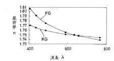
このような傾向は、大口径になればなる程、また長焦点になればなる程顕著に現れる。これは図10に示すようにフリント系ガラスFGがクラウン系ガラスKGより、屈折率が短波長で急峻に高くなるためで、光学ガラス材料の物性に起因しているため、通常の方法では避けられない。
【0009】
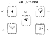
このことをd線、C線、F線のスポットダイアグラムで見ると、図11〜図13の通りに現れる。すなわち、図11(a)〜(e)において、d線のbf=8.0mmの位置でのスポットダイアグラムは、一辺の長さが20μmのボックスの中に全て入り、密集した小さな核があって目標を達成している。つまり、軸上収差が少ない。なお、同図(a)〜(e)におけるスポットダイアグラムの入射角は、それぞれ0.0000、3.4000、4.3000°、6.1800°、6.8000°で、光軸中心からのスポットの距離は0.000mm、10.673mm、13.491mm、19.342mm、21.246mmである。
【0010】
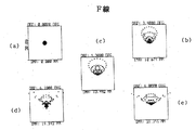
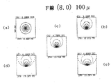
d線のbf=8.0mmの位置で、C線のスポットダイアグラムを見ると、図12(a)〜(e)に示すように20μmのボックス一杯に広がり、核がなく目標を果たすことができない。つまり、軸上収差が大きすぎる。F線のスポットダイアグラムは、図13(a)〜(e)に示すように100μmのボックス一杯に広がっており目標には程遠い。
【0011】
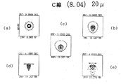
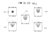
フォーカスしてbfをC線で8.04mm、F線で8.12mmに位置させた場合、C線は図14(a)〜(e)に示すようにかなり目標に近づいてきているが未だ不十分である。F線は図15(a)〜(e)に示すように40μmのボックス一杯に広がっており、到底目標を達成したとは言えない。すなわち、再フォーカスして軸上収差の影響を除去できても、球面収差の色差の影響で目標とする性能を達成することができない。
【0012】
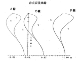
図16に従来のタイプでの対物レンズにおける非点収差曲線を示す。この図から明らかなように、C線、d線、F線の非点収差曲線は大きくずれている。なお、Tは環状方向の非点収差、Sは放射方向の非点収差である。
【0013】
このような傾向は、上記した球面収差曲線と全く同様な理由から、大口径になればなる程、また長焦点になればなる程顕著に現れるため、通常の方法では避けられない。
【0014】
反射系レンズを用いた場合は、色収差の問題は解消されるが、3枚の非球面オファクシス矩形アパーチャーになるため、高精度に非球面加工することが著しく困難になり反射系レンズに比べて高価になったり、使用する光束がリング状になったりするといった別の問題が発生する。したがって、屈折系レンズでこれらの難点を解決することが望ましい。
【0015】
そこで、本発明者らは、大口径で長焦点の顕微鏡用対物レンズの開発、実用化について鋭意検討した結果、レンズ毎に主波長をそれぞれC線、d線、F線とし、各レンズの主波長の光における球面収差曲線、非点収差曲線を略一致するように最適に補正した単色光用の3つの屈折系レンズを製作し、これらのレンズを選択的に使用することにより、いずれのレンズを用いた場合でも、色が異なるだけで、バックフォーカスを調節することなく球面収差、非点収差が最適に補正された鮮鋭な像を広い実視野で、しかも同一の倍率でもって観察または撮影することができることを見出した。このような対物レンズは、可視域全体を使用するが、同時に可視域全体を使用することのない用途、例えば分子生物学等において用いて有効である。
【0016】
本発明は上記した従来の問題、要請および検討結果に基づいてなされたもので、その目的とするところは、大口径、長焦点を可能にし、高い解像度が得られる顕微鏡用対物レンズ組立体を提供することにある。
【0017】
【課題を解決するための手段】
上記目的を達成するために第1の発明は、交換不能な1組のレンズ群と、このレンズ群とそれぞれが一体に交換可能に組み付けられる3組のレンズ群とからなり、上記交換可能な3組のレンズ群は、波長が300〜520nm、500〜620nm、600〜700nmの範囲内のある特定の波長をそれぞれ主波長とし、これらの主波長の光における球面収差曲線を略一致させるように構成されているものである。
【0018】
第2の発明は、交換不能な1組のレンズ群と、このレンズ群とそれぞれが一体に交換可能に組み付けられる3組のレンズ群とからなり、上記交換可能な3組のレンズ群は、波長が300〜520nm、500〜620nm、600〜700nmの範囲内の波長をそれぞれ主波長とし、これらの主波長の光における非点収差曲線を略一致させるように構成されているものである。
【0019】
これらの発明においては、交換可能な3組のレンズ群の主波長の光における球面収差曲線、非点収差曲線がそれぞれ略一致しているので、いずれのレンズ群を用いても、色が異なるだけでバックフォーカスを調節することなく球面収差、非点収差が最適に補正された鮮鋭な像を同一の倍率でもって観察または撮影することができる。また、交換可能な3組のレンズ群は3つの代表的な色を主波長として設計されているので、R,G,Bの可視域全般に有効に使用できる。
【0020】
第3の発明は、上記第1または第2の発明において、上記交換可能な3組の各レンズ群が、それぞれ凹レンズと、この凹レンズよりアッベ数が大きく屈折率が低く設定された凸レンズとで構成されているものである。
この発明においては、交換可能な3組の各レンズ群の球面収差、非点収差をそれぞれ良好に補正する。凸レンズの屈折率nは1.8以下、アッベ数νは45以下が望ましい。凹レンズは相対的に屈折率nが大きく、アッベ数νが小さい。
【0021】
第4の発明は、上記第1、第2または第3の発明において、上記交換可能な3組のレンズ群の主波長の光をそれぞれC線、d線、F線としたものである。
この発明においては、3つの代表色であるC線、d線、F線を主波長として用いているので、可視域全域に有効に使用することができる。
【0022】
第5の発明は、上記第1、第2、第3または第4の発明において、交換可能な3組のレンズ群が交換不能なレンズ群より前側に配置されているものである。
この発明においては、前側に配置すると後側に配置した場合に比べて周縁光線の出射角が小さく、したがって屈折角も小さく、コマ収差等の収差を小さくすることができ、収差補正のためのレンズを追加したりする必要がない。したがって、レンズ設計が後側に配置する場合に比べて容易で、安価に製作することができる。
【0023】
第6の発明は、上記第5の発明において、対物レンズ組立体の前端から後端までの全長をTとしたとき、交換可能なレンズ群を前記対物レンズ組立体の前端から0.35T以内に配置したものである。
この発明においては、レンズ群が0.35T以内であって薄く、周縁光線の出射角が小さく、したがって屈折角も小さくコマ面収差等の収差を小さくする。
【0024】
【発明の実施の形態】
以下、本発明を図面に示す実施の形態に基づいて詳細に説明する。
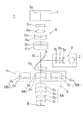
図1は本発明に係る対物レンズ組立体を備えた顕微鏡の概略構成を示す図、図2は対物レンズ組立体を示す図である。これら図において、全体を符号1で示す顕微鏡は、光源2、集光レンズ3、ハーフミラー4、対物レンズ組立体5、撮像レンズ組立体6、撮像装置7等で構成されている。光源2としては、白色電球、レーザー光源等が用いられる。集光レンズ組立体3は、光源2が白色電球の場合、一例として1枚の凹レンズ3aと2枚の凸レンズ3b,3cが用いられ、光源2から出た光を平行光にしてハーフミラー4に導く。ハーフミラー4は、例えば透過率と反射率の比が1対1のものが用いられ、集光レンズ組立体3によって平行光となった光源2からの光を下方に反射して対物レンズ組立体5に導き、被検物8によって反射され対物レンズ組立体5を通って戻ってくる光を透過し、前記撮像装置7に導く。撮像装置7としては、CCD、デジタルカメラ、一眼レフカメラ等が用いられる。被検物8の大きさは直径が43mmである。
【0025】
前記対物レンズ組立体5は、図示してない顕微鏡本体に固定された交換不能な複数のレンズG1 〜G4 ,G7 と、これらのレンズG1 〜G4 ,G7 に対してそれぞれ交換可能に組み付けられる3組のレンズ群5B1 〜5B3 とで構成されており、焦点距離F=180mm、バックフォーカス(bf)>8mm、倍率X10、F/2.5の明るさ、43mmの画面サイズで2.2億画素を越える解像力、テレセントリック条件で可視域全体での使用を可能にしている。画面サイズを43mmに設定した理由は、通常の写真フィルム(36×24mm)による撮影を可能にするためである。
【0026】
交換不能なレンズG1 〜G4 ,G7 のうち、4枚のレンズG1 〜G4 は、1組のレンズ群5Aを構成している。これらのレンズのうちレンズG1 とレンズG2 は、所定の開口数N・Aを確保するためのもので、凸レンズと凹レンズとをエポキシ樹脂、カナダ・バルサム等の光学レンズ用接着剤によって一体的に貼り合わせた2枚一組とするダブレットを構成している。また、レンズG3 とレンズG4 は、対物レンズ組立体5の収差をバランスさせるためのもので、凸レンズと凹レンズとをエポキシ樹脂、カナダ・バルサム等の光学レンズ用接着剤によって一体的に貼り合わせた2枚一組とするダブレットを構成している。残り1枚のレンズG7 は凸レンズからなり、対物レンズ組立体5Bの前側(光源側)に配置されている。
【0027】
レンズG1 〜G4 ,G7 の曲率半径(Rmm)、間隔(dmm)および屈折率(n値&V)を下記表1に示す。
【0028】
【表1】
交換可能な3組のレンズ群5B1 〜5B3 は、それぞれ口径が108mmで、顕微鏡1の図示しない鏡筒に回転自在または移動自在に設けたレンズ転換器11にそれぞれ配設されている。レンズ転換器11は、回転自在に設けられる場合、顕微鏡1の光軸12に対して垂直な面内において回転自在で、その回転中心が光軸12から所定距離離間するように設けられ、内部に前記3組のレンズ群5B1 〜5B3 がレンズ転換器11の回転中心を中心とし光軸12までの距離を半径とする同一円周上に周方向に略等間隔おいて、かつ略同一平面内に位置するようにそれぞれ配設されている。したがって、レンズ転換器11を所要角度回転させると、各レンズ群5B1 〜5B3 の光学中心(光軸)を顕微鏡1の光軸12に対して選択的に一致させることができる。また、通常の顕微鏡における対物レンズ転換器と同様に、スライドガラスのステージに対する着脱操作を容易にするためにレンズ転換器11の中心軸線を光軸12に対して所要角度傾けて回転自在に取付けられるものであってもよい。移動自在に設けられる場合は、顕微鏡の光軸12に対して垂直な面内において移動自在で、内部に3組のレンズ群5B1 〜5B3 がレンズ転換器11の移動方向と平行な同一直線上に位置するように配列される。なお、図1においては中央のレンズ群5B2 の光軸を顕微鏡の光軸12と一致させて被検物8の観察を行っている状態を示している。
【0030】
また、移動可能な3組のレンズ群5B1 〜5B3 は、それぞれ色収差を補正し、バックフォーカスを一致させるとともに、主波長における球面収差曲線、非点収差曲線をそれぞれ略一致させるために凸レンズと凹レンズとで構成されている。各レンズ群5B1 〜5B3 の凸レンズは屈折率nが1.8以下で、アッベ数νが45以上で、凹レンズは相対的に屈折率nが大きく、アッベ数νが小さく設定されている。また、各レンズ群5B1 〜5B3 は、色の3原色であるR,G,Bの各領域、言い換えれば波長が300〜520nm程度の範囲、500〜620nm程度の範囲、600〜700nm程度の範囲内のある特定の波長をそれぞれ主波長としている。
【0031】
さらに、各レンズ群5B1 〜5B3 を詳述すると、図1において中央のレンズ群5B1 は、凸レンズG6 と凹レンズG5 とを貼り合わせた2枚一組とするダブレットからなり、主波長が587.6nmのd線とされる。
【0032】
左側のレンズ群5B2 は、同じく凸レンズG8 と凹レンズG9 とを貼り合わせた2枚一組とするダブレットからなり、主波長が656.3nmのC線とされる。
【0033】
右側のレンズ群5B3 は、同じく凸レンズG10と凹レンズG11とを貼り合わせた2枚一組とするダブレットからなり、主波長が486.1nmのF線とされる。
【0034】
各レンズ群5B1 〜5B3 の曲率半径R1 ,R2 ,R3 ,R4 (mm)、屈折率(n)およびアッベ数(ν)を下記表2に示す。
【0035】
【表2】
凸レンズG6 ,G8 ,G10の中心厚d1 はそれぞれ40mm、凹レンズG7 ,G9 ,G11の中心厚d2 はそれぞれ4.65mmである。なお、レンズ設計において屈折率nとアッベ数νが異なる光学ガラス材料を用いた場合には、各レンズの球面の曲率R1 ,R2 ,R3 ,R4 、中心厚d1 ,d2 が異なることは言うまでもない。
【0037】
このような各レンズ群5B1 〜5B3 の凸レンズG6 ,G8 ,G10と凹レンズG5 ,G9 ,G11は、それぞれエポキシ樹脂、カナダ・バルサム等の光学レンズ用接着剤によって一体的に貼り合わされているが、これに限らず両レンズ間に空隙を設けたものか、またはシリコーンオイルを介在させたものであってもよい。
【0038】
さらに、各レンズ群5B1 〜5B3 は、対物レンズ組立体5の全長をTとすると、対物レンズ組立体5の前端から0.35T以内に位置するように配置されている。このため、各レンズ群5B1 〜5B3 の厚さ、すなわち凸レンズの前端から凹レンズの後端までの距離は、最大でも0.35T(レンズG7 を用いない場場合)である。なお、上記説明においては対物レンズ組立体5の焦点距離を180mmとして説明したが、厳密には各レンズ群5B1 〜5B3 によってきわめて僅かではあるが異なり、レンズ群5B1 を用いた場合は180.0001mm、レンズ群5B2 を用いた場合は180.0003mm、レンズ群5B3 を用いた場合は179.9997mmである。
【0039】
凸レンズG6 ,G8 ,G10の材料としては、屈折率の低いクラウン系の光学ガラス材料が用いられ、凹レンズG5 ,G9 ,G11の材料としてはフリント系の光学ガラス材料が用いられる。この他、凸レンズと凹レンズの材料としては、クラウン系とフリント系のガラス材料に限らず、人工サファイア、水晶、蛍石等からなる異常分散性光学材料を使用することも可能である。
【0040】
前記撮像レンズ組立体6は、複数枚の凸レンズと凹レンズG12〜G17とで構成されており、対物レンズ組立体5およびハーフミラー4を透過した被検物8の映像光を撮像装置7に導く。撮像レンズ組立体6の倍率Xは1で、ハーフミラー4を透過する映像光は、光軸12に平行な平行光である。
【0041】
このような顕微鏡1において、被検物8が貼り付けられたスライドガラスをステージの上に設置する。次いで、交換可能な3つのレンズ群5B1 〜5B3 のうちのいずれか1つ、例えばレンズ群5B1 を選択して光軸12と一致させ、光源2を点灯させる。光源2から出た光は集光レンズ組立体3によって平行光に変換された後、ハーフミラー4によって下方に反射され、対物レンズ組立体5によって被検物8の表面に集光される。そして、被検物8の表面で反射した光は、再び対物レンズ組立体5を通り、さらにハーフミラー4を透過した後、撮像レンズ組立体6によって撮像装置7の受光面7aに投影され、被検物8の映像としてCCDによって撮像されるかまたはデジタルカメラや一眼レフカメラによって撮影される。
【0042】
この場合、被検物8の撮像または撮影に際してレンズ群5B1 を用いているため、その主波長であるd線の色(黄色)の画像が得られる。レンズ群5B2 を用いた場合はC線の色(赤)の画像が得られ、レンズ群5B3 を用いた場合はF線の色(青)の画像が得られる。
【0043】
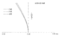
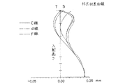
図3と図4に各レンズ群5B1 〜5B3 の球面収差曲線と非点収差曲線をそれぞれ示す。これらの図から明らかなように、3つのレンズ群5B1 〜5B3 の球面収差曲線と非点収差曲線は、それぞれ略一致しており非常によく似た補正状況を示していることが判る。これは、光学レンズの特性からして唯1つのレンズ群ではC線、d線、F線の全ての光における球面収差曲線および非点収差曲線を略一致させることは不可能であるが、各レンズ群5B1 〜5B3 の主波長をそれぞれC線、d線、F線の単波長としているため、レンズ群5B1 についてはd線の光における球面収差曲線および非点収差曲線の収差補正を適正に行うだけでよく、レンズ群5B2 についてはC線の光における球面収差曲線および非点収差曲線の収差補正をd線の球面収差曲線および非点収差曲線とそれぞれ略一致するように適正に行うだけでよく、またレンズ群5B3 についてはF線の光における球面収差曲線および非点収差曲線の収差補正をd線、C線の光における球面収差曲線および非点収差曲線とそれぞれ略一致するように行うだけでよいからである。したがって、いずれのレンズ群5B1 〜5B3 を用いて被検物8を撮像または撮影した場合でも、映像の色が異なるだけでレンズ群を交換した時にバックフォーカスする必要が全くなく、同一の倍率で同一の像を撮像または撮影することができる。
【0044】
また、対物レンズ組立体5のレンズ設計に当たっては、交換可能な3つのレンズ群5B1 〜5B3 を交換不能な1組のレンズ群5Aの前側に配置しているので、レンズ設計が容易で、安価に製作することができる。すなわち、後側に配置した場合は、各レンズ群5B1 〜5B3 の縁近くを通る周縁光線の出射角が大きくなり、屈折角が大きくなるため画面周辺部に影響の大きい収差が生じる。このため、その収差を補正するためのレンズをさらに追加する必要がある。したがって、レンズ設計が複雑になり高価になる。一方、前側に配置した場合は後側に配置した場合に比べて周縁光線の出射角が小さいため屈折角も小さく、画面周縁部に収差が生じず、レンズの枚数を増やさないでも良好な映像を得ることができる。
【0045】
また、被検物8が直径43mmの大きなものであっても、全体を照射することができるので、ステージを動かして撮像または撮影したい箇所を探す必要がなく、被検物8全体を一枚の画面に撮像または撮影することができる。
【0046】
図5〜図7にd線、C線、F線のスポットダイアグラムを示す。
図5において、d線のスポットダイアグラムは、どの画角でも20μmのボックスの中に全て入り、密集した小さな核があって目標を達している。同図(a)〜(e)におけるスポットダイアグラムの入射角は、それぞれ0.0000、3.4000、4.3000°、6.1800°、6.8000°で、光軸中心からのスポットの距離は0.000mm、10.673mm、13.491mm、19.342mm、21.246mmであった。
【0047】
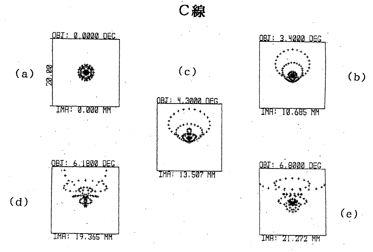
図6において、C線についてもd線と同様に密集した小さな核があって達成できていることが判る。同図(a)〜(e)におけるスポットダイアグラムの入射角は、それぞれ0.0000、3.4000、4.3000°、6.1800°、6.8000°で、光軸中心からのスポットの距離は0.000mm、10.685mm、13.507mm、19.365mm、21.272mmであった。
【0048】
一方、F線の光はC線とd線の光における球面収差曲線とは異なり補正過剰なため、補正するのに最も困難であったが、光線をカットして少なくすることにより、図7に示すように、C線、d線と略同様なスポットダイアグラムが得られた。同図(a)〜(e)におけるスポットダイアグラムの入射角は、それぞれ0.0000、3.4000、4.3000°、6.1800°、6.8000°で、光軸中心からのスポットの距離は0.000mm、10.674mm、13.492mm、19.342mm、21.246mmであった。
【0049】
以上のことから、スポットが80%集中する直径が、画面中心で3μmくらい、隅部で5μm以下にまとまっていて、この種の大口径、長焦点レンズでは従来では期待できなかった高性能であることが判る。
【0050】
このような顕微鏡1は、細胞生物学、病理学等の分野において、遺伝子、タンパク質、RNA、組織接片などの被検物を観察する際に用いて有効である。すなわち、これらの被検物は、励起光を被検物に照射すると蛍光を発するので、3つのレンズ群5B1 〜5B3 のうちからその色に近い主波長のレンズ群を選択して観察すると、被検物を良好に観察することができる。蛍光物質の種類によって発する蛍光の分光分布は、さして広い波長域にはわたらないが、用途により蛍光物質が何種類も使われるので、その全部をカバーする波長域はかなり広い。そこで、3つのレンズ群5B1 〜5B3 の主波長をC線、d線、F線とすることにより、赤色領域、緑色領域、青色領域の可視域全般にわたる蛍光物質に対して使用が可能である。
【0051】
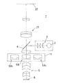
図8は本発明の他の実施の形態を示す顕微鏡の概略構成図である。
この実施の形態は、図1に示した撮像レンズ組立体6と撮像装置7の代わりに結像レンズ組立体21と投影スクリーン22を用いている。顕微鏡1の倍率は10倍である。投影スクリーン22は、直径が430mmである。その他の構造は、図1に示した実施の形態と全く同一であるため、同一構成部材のものについては同一符号をもって示し、その説明を省略する。
【0052】
このような顕微鏡1においては、被検物8の像を結像レンズ組立体21によって投影スクリーン22に投射させることができるので、観察者は投影スクリーン22に投影された被検物8の像を肉眼で観察することができる。
【0053】
なお、上記した実施の形態においては、交換可能な3つのレンズ群5B1 〜5B3 の主波長して、C線、d線、F線を用いた例を示したが、本発明はこれに何等限定されるものではなく、赤色、緑色、青色の各領域の波長の範囲内におけるある特定の適宜な波長の線、例えば、D線(589.3nm)、E線(527.0nm)、G線(430.8nm)等を主波長として用いてもよい。
また、撮像レンズ組立体6や結像レンズ組立体21の代わりに接眼レンズを用いることも可能である。
【0054】
【発明の効果】
以上説明したように本発明に係る顕微鏡用対物レンズ組立体によれば、可視域全体で使用することができ、特に特定波長の単色光による観察であるため、励起光を被検物に照射し、蛍光を発しさせたり、あるいは被検物を化学染色して観察を行う細胞生物学、病理学等の分野に用いて好適である。
【0055】
また、長焦点で大口径の屈折系レンズが得られ、いずれのレンズ群を用いた場合でもバックフォーカスの調整をする必要がなく、被検物を同一の倍率で観察することができる。
【0056】
また、実視野を広くすることができるため大きな被検物の全画面を一度に撮影することが可能でき、画像解析するときコンピュータによる解析処理が容易で、大量の被検物を迅速に解析することができる。さらに、レンズ群の交換時にその都度バックフォーカスの調整をする必要がないため、顕微鏡の取扱いも容易である。
【0057】
また、本発明は交換可能なレンズ群を交換不能なレンズ群より前側に配置しているので、後側に配置した場合に比べて屈折角が小さく、コマ収差等の収差を小さくすることができ、収差補正のためのレンズを追加したりする必要がなく、レンズ設計が容易で、安価に製作することができる。
【0058】
さらに、本発明によれば、レンズ群の厚さが薄く、周縁光線の出射角を小さくでき、したがって屈折角も小さく、コマ面収差等の収差を小さくすることができる。
【図面の簡単な説明】
【図1】 本発明に係る対物レンズ組立体を備えた顕微鏡の概略構成を示す図である。
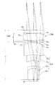
【図2】 対物レンズ組立体を示す図である。
【図3】 レンズ群の球面収差曲線を示す図である。
【図4】 レンズ群の非点収差曲線を示す図である。
【図5】 d線のスポットダイアグラムである。
【図6】 C線のスポットダイアグラムである。
【図7】 F線のスポットダイアグラムである。
【図8】 本発明の他の実施の形態を示す顕微鏡の概略構成図である。
【図9】 従来の対物レンズにおける球面収差曲線を示す図である。
【図10】 クラウン系ガラスとフリント系ガラスの屈折率と波長の関係を示す図である。
【図11】 従来の対物レンズにおけるd線のスポットダイアグラムである。
【図12】 従来の対物レンズにおけるC線のスポットダイアグラムである。
【図13】 従来の対物レンズにおけるF線のスポットダイアグラムである。
【図14】 フォーカス後のC線のスポットダイアグラムである。
【図15】 フォーカス後のF線のスポットダイアグラムである。
【図16】 従来の対物レンズにおける非点収差曲線を示す図である。
【符号の説明】
1…顕微鏡、2…光源、3…集光レンズ組立体、4…ハーフミラー、5…対物レンズ組立体、5A…交換不能なレンズ群、5B1 〜5B3 …交換可能なレンズ群、6…撮像レンズ組立体、7…撮像装置、8…被検物、12…光軸、21…結像レンズ組立体、22…投影スクリーン、G6 ,G8 ,G10…凸レンズ、 G5 ,G9 ,G11…凹レンズ。[0001]
BACKGROUND OF THE INVENTION
The present invention relates to an objective lens assembly for a microscope, and in particular, enables a large aperture and a long focal length and obtains a high resolution and is suitable for use in fields such as cell biology and pathology. About.
[0002]
[Prior art]
Usually, an objective lens having a magnification X of 10 used in a microscope has a real field of view of about 1.8 to 2.5 mm when the focal length f is about 1.5 to 20 mm. Increasing the magnification naturally reduces the focal length and narrows the real field of view.
[0003]
By the way, in the field of cell biology, when observing cellular components such as genes, proteins, and RNA (ribonucleic acid) with a microscope, they are usually irradiated with an appropriate fluorescent probe, reacted, and then captured by a scanner for expression. The state of the image is analyzed. However, the time required for scanning cannot be ignored. In the field of pathology, a tissue section fixed on a slide glass is subjected to histochemical staining, and then the slide glass is placed on a stage, and the stage is moved to observe a tissue contact piece. Therefore, when the object to be observed is larger than the real field of view of the objective lens, the number of times the stage is moved increases, so that a long time is required for observation.
[0004]
[Problems to be solved by the invention]
As described above, since a conventional microscope has a narrow real field of view, it is necessary to move the stage in order to observe a specimen such as a large tissue section in a wide field of view, and the number of times increases. Therefore, for example, when an object having a diameter of about 43 mm is to be observed, it is necessary to divide and observe for a long time. In this way, if observation takes a long time, if the specimen is a living tissue section, the tissue in the unobserved part is mutated or killed while observing a certain part of the tissue section. Therefore, there is a problem that the entire tissue cannot be observed in a short time. For this reason, in the fields of cell biology, pathology, etc., there is a demand for the development of a microscope capable of observing a large test object having a wide real field of view in a short time and in a sharp manner.
[0005]
Therefore, if a conventional objective lens is simply scaled up 10 times to produce a refractive objective lens having a diameter of 108 mm and a focal length of 180 mm, for example, the refraction angle varies depending on the wavelength of light, and the back focus (bf ) Is different, focusing on one wavelength and using it for other wavelengths results in out of focus (chromatic aberration). This is a problem that only needs to be refocused, but the shape of the spherical aberration curve and astigmatism curve differ according to the characteristics of the change in the refractive index of the optical glass with respect to the wavelength. I can't.
[0006]
FIG. 9 shows a spherical aberration curve in the conventional objective lens. This figure shows three representative colors in the red (R), green (G), and blue (B) regions: C line (wavelength: 656.3 nm), d line (wavelength: 587.6 nm), F line ( This shows a spherical aberration curve in light having a wavelength of 486.1 nm) and is corrected so as to obtain the highest performance by paying attention only to the d-line. That is, correction is performed so that the spherical aberration of the d-line is minimized in the paraxial ray. However, if correction is performed by focusing on only the d line, the C line becomes under (undercorrection) and the F line becomes over (overcorrection), and the distance between the F line and the d line is 0.074 mm. There is an axial aberration of 0.065 mm between the lines, which can be improved by refocusing, but the spherical aberration is the limit, -0.042 mm for the d line, -0.069 mm for the C line, and +0. With this lens in which the Petzfahl sum (on-axis characteristic of the curvature of a planar object image by the optical system) is plus, it is difficult to obtain satisfactory performance particularly with F-line.
[0007]
For these three wavelengths, the combination of a convex lens made of crown glass and a concave lens made of flint glass tries to optimize the line of any wavelength to achieve high performance. However, it does not have high performance for C-line. In other words, the spherical aberration curves for the C line, d line, and F line cannot be substantially matched.
[0008]
Such a tendency becomes more prominent as the aperture becomes larger and as the focal length becomes longer. As shown in FIG. 10, the flint glass FG has a refractive index that is sharply higher at a short wavelength than the crown glass KG, and is caused by the physical properties of the optical glass material. Absent.
[0009]
When this is seen in the spot diagrams of d-line, C-line, and F-line, it appears as shown in FIGS. That is, in FIGS. 11 (a) to 11 (e), the spot diagram at the position of b line = 8.0 mm of the d line is all inside a box with a side length of 20 μm, and there are small nuclei that are dense. The goal has been achieved. That is, there is little axial aberration. In addition, the incident angles of the spot diagrams in FIGS. 4A to 4E are 0.0000, 3.4000, 4.3000 °, 6.1800 °, and 6.8000 °, respectively, and the spot from the center of the optical axis. Are 0.000 mm, 10.673 mm, 13.491 mm, 19.342 mm, and 21.246 mm.
[0010]
When the spot diagram of the C line is seen at the position of b line = 8.0 mm of the d line, as shown in FIGS. 12 (a) to 12 (e), it spreads over the 20 μm box and there is no nucleus, and the target cannot be achieved. . That is, the axial aberration is too large. As shown in FIGS. 13A to 13E, the spot diagram of the F line spreads over the 100 μm box and is far from the target.
[0011]
When focusing and bf is positioned at 8.04 mm for the C line and 8.12 mm for the F line, the C line is approaching the target as shown in FIGS. It is enough. As shown in FIGS. 15 (a) to 15 (e), the F line spreads over the 40 μm box, and it cannot be said that the target has been achieved. That is, even if refocusing can remove the influence of axial aberration, the target performance cannot be achieved due to the influence of the color difference of spherical aberration.
[0012]
FIG. 16 shows an astigmatism curve in an objective lens of a conventional type. As is apparent from this figure, the astigmatism curves of the C line, d line, and F line are greatly deviated. T is the astigmatism in the annular direction, and S is the astigmatism in the radial direction.
[0013]
For the same reason as the above-mentioned spherical aberration curve, such a tendency becomes more noticeable as the aperture becomes larger and the focal length becomes longer.
[0014]
When a reflective lens is used, the problem of chromatic aberration is solved. However, since three aspherical off-axis rectangular apertures are used, it is extremely difficult to process aspherical surfaces with high accuracy, and it is more expensive than a reflective lens. Another problem arises that the light flux used becomes a ring shape. Therefore, it is desirable to solve these difficulties with a refractive lens.
[0015]
Thus, as a result of intensive studies on the development and practical application of a large-diameter, long-focus microscope objective lens, the present inventors have determined that the main wavelengths of each lens are C-line, d-line, and F-line, respectively. By producing three refractive lenses for monochromatic light that have been optimally corrected so that the spherical aberration curve and astigmatism curve in the light of the wavelength substantially coincide with each other, any lens can be used by selectively using these lenses. Even when using, you can observe or shoot a sharp image with spherical aberration and astigmatism optimally corrected with a wide real field of view, with the same magnification, without adjusting the back focus, only with different colors I found that I can do it. Such an objective lens uses the entire visible range, but is effective for use in applications that do not use the entire visible range, such as molecular biology.
[0016]
The present invention has been made on the basis of the above-described conventional problems, requirements, and examination results. The object of the present invention is to provide an objective lens assembly for a microscope that enables a large aperture and a long focal length, and that provides high resolution. There is to do.
[0017]
[Means for Solving the Problems]
In order to achieve the above object, the first invention comprises a set of non-exchangeable lens groups and three sets of lens groups each of which is assembled so as to be interchangeable together. The pair of lens groups are configured such that specific wavelengths within the range of 300 to 520 nm, 500 to 620 nm, and 600 to 700 nm are set as the main wavelengths, and the spherical aberration curves in the light of these main wavelengths are substantially matched. It is what has been.
[0018]
The second invention comprises a set of non-exchangeable lens groups and three lens groups each of which is assembled so as to be interchangeable with each other. Is configured such that the wavelengths in the range of 300 to 520 nm, 500 to 620 nm, and 600 to 700 nm are the main wavelengths, respectively, and the astigmatism curves in the light of these main wavelengths are substantially matched.
[0019]
In these inventions, since the spherical aberration curve and the astigmatism curve in the principal wavelength light of the three interchangeable lens groups are substantially the same, only the color is different regardless of which lens group is used. Thus, a sharp image in which spherical aberration and astigmatism are optimally corrected can be observed or photographed at the same magnification without adjusting the back focus. In addition, since the three interchangeable lens groups are designed with three representative colors as the main wavelengths, they can be effectively used in the entire visible range of R, G, and B.
[0020]
According to a third invention, in the first or second invention, each of the three interchangeable lens groups includes a concave lens and a convex lens having a larger Abbe number and a lower refractive index than the concave lens. It is what has been.
In the present invention, the spherical aberration and astigmatism of each of the three interchangeable lens groups are corrected satisfactorily. The refractive index n of the convex lens is desirably 1.8 or less, and the Abbe number ν is desirably 45 or less. The concave lens has a relatively large refractive index n and a small Abbe number ν.
[0021]
According to a fourth invention, in the first, second, or third invention, the light having the main wavelength of the three interchangeable lens groups is a C-line, a d-line, and an F-line, respectively.
In the present invention, the three representative colors C-line, d-line, and F-line are used as the main wavelengths, so that they can be used effectively over the entire visible range.
[0022]
According to a fifth invention, in the first, second, third, or fourth invention, three interchangeable lens groups are arranged in front of the non-exchangeable lens group.
In the present invention, when arranged on the front side, the emission angle of the marginal ray is smaller than when arranged on the rear side, and hence the refraction angle is also small, and aberrations such as coma aberration can be reduced. There is no need to add. Therefore, it is easier and cheaper to manufacture than when the lens design is arranged on the rear side.
[0023]
In a sixth aspect based on the fifth aspect, when the total length from the front end to the rear end of the objective lens assembly is T, the interchangeable lens group is within 0.35 T from the front end of the objective lens assembly. It is arranged.
In the present invention, the lens group is within 0.35T and is thin, the emission angle of the marginal ray is small, the refraction angle is also small, and aberrations such as coma aberration are reduced.
[0024]
DETAILED DESCRIPTION OF THE INVENTION
Hereinafter, the present invention will be described in detail based on embodiments shown in the drawings.
FIG. 1 is a diagram showing a schematic configuration of a microscope provided with an objective lens assembly according to the present invention, and FIG. 2 is a diagram showing an objective lens assembly. In these drawings, the microscope denoted as a whole by
[0025]
The
[0026]
Of the non-replaceable lenses G1 to G4 and G7, the four lenses G1 to G4 constitute a set of
[0027]
Table 1 below shows the radius of curvature (Rmm), distance (dmm) and refractive index (n value & V) of the lenses G1 to G4 and G7.
[0028]
[Table 1]
Three interchangeable lens groups 5B1 to 5B3 each have a diameter of 108 mm, and are respectively disposed in a
[0030]
The three movable lens groups 5B1 to 5B3 correct the chromatic aberration, match the back focus, and substantially match the spherical aberration curve and the astigmatism curve at the main wavelength respectively. It consists of The convex lenses of the lens groups 5B1 to 5B3 have a refractive index n of 1.8 or less, an Abbe number ν of 45 or more, and a concave lens has a relatively large refractive index n and a small Abbe number ν. Each of the lens groups 5B1 to 5B3 has R, G, and B regions which are the three primary colors, in other words, the wavelength range is about 300 to 520 nm, the range is about 500 to 620 nm, and the range is about 600 to 700 nm. Each of the specific wavelengths is the main wavelength.
[0031]
Further, each lens group 5B1 to 5B3 will be described in detail. In FIG. 1, the central lens group 5B1 is composed of a doublet in which a convex lens G6 and a concave lens G5 are bonded together, and has a main wavelength of 587.6 nm. d line.
[0032]
The left lens group 5B2 is composed of a doublet in which a convex lens G8 and a concave lens G9 are bonded together, and is a C-line having a main wavelength of 656.3 nm.
[0033]
The right lens group 5B3 is composed of a doublet in which a convex lens G10 and a concave lens G11 are bonded together, and is an F-line having a main wavelength of 486.1 nm.
[0034]
Table 2 shows the radii of curvature R1, R2, R3, R4 (mm), the refractive index (n), and the Abbe number (ν) of each of the lens groups 5B1 to 5B3.
[0035]
[Table 2]
The center thicknesses d1 of the convex lenses G6, G8 and G10 are 40 mm, and the center thicknesses d2 of the concave lenses G7, G9 and G11 are 4.65 mm. Needless to say, when an optical glass material having a refractive index n and an Abbe number ν different in lens design is used, the spherical curvatures R1, R2, R3, R4 and center thicknesses d1, d2 of each lens are different.
[0037]
The convex lenses G6, G8, and G10 and the concave lenses G5, G9, and G11 of the lens groups 5B1 to 5B3 are integrally bonded to each other with an optical lens adhesive such as epoxy resin and Canadian balsam. However, the present invention is not limited to this, and a lens having a gap between the two lenses or a silicone oil interposed may be used.
[0038]
Further, each of the lens groups 5B1 to 5B3 is disposed so as to be located within 0.35T from the front end of the
[0039]
As the material of the convex lenses G6, G8, and G10, a crown type optical glass material having a low refractive index is used, and as the material of the concave lenses G5, G9, and G11, a flint type optical glass material is used. In addition, the material of the convex lens and the concave lens is not limited to a crown-type and flint-type glass material, and an anomalous dispersion optical material made of artificial sapphire, quartz, fluorite, or the like can also be used.
[0040]
The
[0041]
In such a
[0042]
In this case, since the lens group 5B1 is used for imaging or photographing the
[0043]
3 and 4 show the spherical aberration curve and astigmatism curve of each lens group 5B1 to 5B3, respectively. As can be seen from these drawings, the spherical aberration curves and astigmatism curves of the three lens groups 5B1 to 5B3 are substantially coincident with each other, indicating a very similar correction situation. This is because the spherical aberration curve and the astigmatism curve in all the light of the C-line, d-line, and F-line cannot be substantially matched with only one lens group because of the characteristics of the optical lens. Since the main wavelengths of the lens groups 5B1 to 5B3 are the single wavelengths of the C-line, d-line, and F-line, respectively, the lens group 5B1 appropriately corrects the aberrations of the spherical aberration curve and astigmatism curve in the d-line light. For the lens group 5B2, the spherical aberration curve and the astigmatism curve in the C-line light need only be corrected appropriately so that they substantially coincide with the d-line spherical aberration curve and the astigmatism curve, respectively. For the lens group 5B3, the spherical aberration curve and the astigmatism curve correction for the F-line light are performed so as to substantially match the spherical aberration curve and the astigmatism curve for the d-line and C-line light, respectively. This is because it only needs to be done. Therefore, even when any of the lens groups 5B1 to 5B3 is used to image or photograph the
[0044]
Further, in designing the lens of the
[0045]
Further, even if the
[0046]
5 to 7 show spot diagrams of d-line, C-line, and F-line.
In FIG. 5, the d-line spot diagram is all in a 20 μm box at any angle of view, and there are dense nuclei to reach the target. The incident angles of the spot diagrams in FIGS. 4A to 4E are 0.0000, 3.4000, 4.3000 °, 6.1800 °, and 6.8000 °, respectively, and the distance of the spot from the optical axis center. Were 0.000 mm, 10.673 mm, 13.491 mm, 19.342 mm, and 21.246 mm.
[0047]
In FIG. 6, it can be seen that the C line is also achieved with small nuclei that are dense like the d line. The incident angles of the spot diagrams in FIGS. 4A to 4E are 0.0000, 3.4000, 4.3000 °, 6.1800 °, and 6.8000 °, respectively, and the distance of the spot from the optical axis center. Were 0.000 mm, 10.855 mm, 13.507 mm, 19.365 mm, and 21.272 mm.
[0048]
On the other hand, the F-line light is overcorrected unlike the spherical aberration curves for the C-line and d-line light, and is therefore the most difficult to correct. As shown, a spot diagram substantially similar to the C line and d line was obtained. The incident angles of the spot diagrams in FIGS. 4A to 4E are 0.0000, 3.4000, 4.3000 °, 6.1800 °, and 6.8000 °, respectively, and the distance of the spot from the optical axis center. Were 0.000 mm, 10.694 mm, 13.492 mm, 19.342 mm, and 21.246 mm.
[0049]
From the above, the diameter at which 80% of the spots are concentrated is about 3 μm at the center of the screen and 5 μm or less at the corners, which is a high performance that could not be expected with this type of large aperture and long focus lens. I understand that.
[0050]
Such a
[0051]
FIG. 8 is a schematic configuration diagram of a microscope showing another embodiment of the present invention.
In this embodiment, an
[0052]
In such a
[0053]
In the above-described embodiment, an example in which C-line, d-line, and F-line are used as the main wavelengths of the three interchangeable lens groups 5B1 to 5B3 is shown, but the present invention is not limited to this. In particular, a line having a certain appropriate wavelength within the wavelength range of each of the red, green, and blue regions, for example, a D line (589.3 nm), an E line (527.0 nm), a G line ( 430.8 nm) or the like may be used as the dominant wavelength.
It is also possible to use an eyepiece instead of the
[0054]
【The invention's effect】
As described above, according to the objective lens assembly for a microscope according to the present invention, it can be used in the entire visible range, and in particular, since it is observation with monochromatic light of a specific wavelength, the excitation light is irradiated onto the test object. It is suitable for use in the fields of cell biology, pathology, etc. in which fluorescence is emitted or chemical observation is performed on a test substance for observation.
[0055]
In addition, a refraction lens having a long focal length and a large aperture is obtained, and it is not necessary to adjust the back focus regardless of which lens group is used, and the test object can be observed at the same magnification.
[0056]
In addition, since the real field of view can be widened, it is possible to capture the entire screen of a large test object at one time, and it is easy to perform analysis processing by a computer when analyzing images, and a large amount of test objects can be analyzed quickly. be able to. Furthermore, since it is not necessary to adjust the back focus each time the lens group is replaced, handling of the microscope is easy.
[0057]
In the present invention, the interchangeable lens group is arranged in front of the non-exchangeable lens group, so that the refraction angle is smaller than that of the rear lens group, and coma and other aberrations can be reduced. Further, it is not necessary to add a lens for correcting aberrations, and the lens design is easy and can be manufactured at low cost.
[0058]
Furthermore, according to the present invention, the thickness of the lens group is thin, the emission angle of the peripheral ray can be reduced, and therefore the refraction angle is also small, and aberrations such as coma aberration can be reduced.
[Brief description of the drawings]
FIG. 1 is a diagram showing a schematic configuration of a microscope provided with an objective lens assembly according to the present invention.
FIG. 2 is a diagram showing an objective lens assembly.
FIG. 3 is a diagram illustrating a spherical aberration curve of a lens group.
FIG. 4 is a diagram showing an astigmatism curve of a lens group.
FIG. 5 is a spot diagram of d line.
FIG. 6 is a spot diagram of C line.
FIG. 7 is a spot diagram of F line.
FIG. 8 is a schematic configuration diagram of a microscope showing another embodiment of the present invention.
FIG. 9 is a diagram showing a spherical aberration curve in a conventional objective lens.
FIG. 10 is a diagram showing the relationship between the refractive index and wavelength of crown-based glass and flint-based glass.
FIG. 11 is a spot diagram of d-line in a conventional objective lens.
FIG. 12 is a spot diagram of C line in a conventional objective lens.
FIG. 13 is a spot diagram of F line in a conventional objective lens.
FIG. 14 is a spot diagram of C line after focusing.
FIG. 15 is a spot diagram of an F line after focusing.
FIG. 16 is a diagram showing an astigmatism curve in a conventional objective lens.
[Explanation of symbols]
DESCRIPTION OF
Claims (6)
上記交換可能な3組の各レンズ群は、それぞれ凹レンズと、この凹レンズよりアッベ数が大きく屈折率が低く設定された凸レンズとで構成されていることを特徴とする顕微鏡用対物レンズ組立体。The microscope objective lens assembly according to claim 1 or 2,
3. The microscope objective lens assembly according to claim 1, wherein each of the three interchangeable lens groups includes a concave lens and a convex lens having an Abbe number larger than that of the concave lens and a lower refractive index.
上記交換可能な3組のレンズ群の主波長の光がそれぞれC線、d線、F線であることを特徴とする顕微鏡用対物レンズ組立体。The objective lens assembly for a microscope according to claim 1, 2, or 3,
The objective lens assembly for a microscope, characterized in that light having a main wavelength of the three interchangeable lens groups is a C line, a d line, and an F line, respectively.
交換可能な3組のレンズ群が交換不能なレンズ群より前側に配置されていることを特徴とする顕微鏡用対物レンズ組立体。The objective lens assembly for a microscope according to claim 1, 2, 3, or 4,
3. An objective lens assembly for a microscope, wherein three interchangeable lens groups are arranged in front of a non-exchangeable lens group.
対物レンズ組立体の前端から後端までの全長をTとしたとき、交換可能なレンズ群を前記対物レンズ組立体の前端から0.35T以内に配置したことを特徴とする顕微鏡用対物レンズ組立体。The microscope objective lens assembly according to claim 5,
An objective lens assembly for a microscope, wherein an interchangeable lens group is disposed within 0.35 T from the front end of the objective lens assembly, where T is the total length from the front end to the rear end of the objective lens assembly. .
Priority Applications (1)
| Application Number | Priority Date | Filing Date | Title |
|---|---|---|---|
| JP2001144520A JP4792170B2 (en) | 2001-05-15 | 2001-05-15 | Objective lens assembly for microscope |
Applications Claiming Priority (1)
| Application Number | Priority Date | Filing Date | Title |
|---|---|---|---|
| JP2001144520A JP4792170B2 (en) | 2001-05-15 | 2001-05-15 | Objective lens assembly for microscope |
Publications (2)
| Publication Number | Publication Date |
|---|---|
| JP2002341250A JP2002341250A (en) | 2002-11-27 |
| JP4792170B2 true JP4792170B2 (en) | 2011-10-12 |
Family
ID=18990457
Family Applications (1)
| Application Number | Title | Priority Date | Filing Date |
|---|---|---|---|
| JP2001144520A Expired - Fee Related JP4792170B2 (en) | 2001-05-15 | 2001-05-15 | Objective lens assembly for microscope |
Country Status (1)
| Country | Link |
|---|---|
| JP (1) | JP4792170B2 (en) |
Families Citing this family (2)
| Publication number | Priority date | Publication date | Assignee | Title |
|---|---|---|---|---|
| JP2006267530A (en) * | 2005-03-24 | 2006-10-05 | Mitsubishi Electric Corp | Illumination device and projection display device |
| EP4508872A1 (en) * | 2022-04-11 | 2025-02-19 | Ventana Medical Systems, Inc. | Image sensing system and method for imaging |
-
2001
- 2001-05-15 JP JP2001144520A patent/JP4792170B2/en not_active Expired - Fee Related
Also Published As
| Publication number | Publication date |
|---|---|
| JP2002341250A (en) | 2002-11-27 |
Similar Documents
| Publication | Publication Date | Title |
|---|---|---|
| US6994668B2 (en) | Four-group endoscope objective lens | |
| CN105074531B (en) | Amplify endoscope optical system | |
| EP2490061A1 (en) | Imaging lens, camera and personal digital assistant | |
| JP6838445B2 (en) | Imaging lens, imaging device and inspection device | |
| EP0506955A1 (en) | Apochromatic relay lens systems suitable for use in a high definition telecine apparatus. | |
| JPWO2017216969A1 (en) | Bright relay optical system and optical system for rigid mirror using the same, rigid mirror | |
| JP2019191274A (en) | Image capturing optical system and microscope system | |
| CN110082895B (en) | Modular zoom lens with high optical expansion for machine vision | |
| JPH10268188A (en) | Large-aperture lens for photographic at low illuminance | |
| US7057804B2 (en) | Ultraviolet imaging system | |
| KR20030025828A (en) | Projection lens and projector provided with the same | |
| CN119291899B (en) | A visible-ultraviolet dual-wavelength microscope objective lens and optical system | |
| JP2006084886A (en) | Lens device | |
| JP4792170B2 (en) | Objective lens assembly for microscope | |
| WO2020021662A1 (en) | Microscope objective lens and microscope | |
| JP4160270B2 (en) | Imaging optics and lens barrel | |
| CN217689587U (en) | Line dispersion lens and line spectrum confocal sensor | |
| JPH05119259A (en) | Zoom lens | |
| JP4720319B2 (en) | Objective lens | |
| CN117337385A (en) | Detection lens and detection method for head-mounted display device | |
| CN118567064B (en) | Optical lens | |
| US20060285219A1 (en) | Tube lens unit with chromatically compensating effect | |
| SU1658114A1 (en) | Planapochromatic objective lens of microscope | |
| RU2098853C1 (en) | Planoapochromatic microlens | |
| JPH1062692A (en) | Microscopy photography lens |
Legal Events
| Date | Code | Title | Description |
|---|---|---|---|
| A621 | Written request for application examination |
Free format text: JAPANESE INTERMEDIATE CODE: A621 Effective date: 20080326 |
|
| A131 | Notification of reasons for refusal |
Free format text: JAPANESE INTERMEDIATE CODE: A131 Effective date: 20110329 |
|
| TRDD | Decision of grant or rejection written | ||
| A521 | Request for written amendment filed |
Free format text: JAPANESE INTERMEDIATE CODE: A821 Effective date: 20110525 |
|
| A01 | Written decision to grant a patent or to grant a registration (utility model) |
Free format text: JAPANESE INTERMEDIATE CODE: A01 Effective date: 20110628 |
|
| A01 | Written decision to grant a patent or to grant a registration (utility model) |
Free format text: JAPANESE INTERMEDIATE CODE: A01 |
|
| A61 | First payment of annual fees (during grant procedure) |
Free format text: JAPANESE INTERMEDIATE CODE: A61 Effective date: 20110725 |
|
| FPAY | Renewal fee payment (event date is renewal date of database) |
Free format text: PAYMENT UNTIL: 20140729 Year of fee payment: 3 |
|
| R150 | Certificate of patent or registration of utility model |
Free format text: JAPANESE INTERMEDIATE CODE: R150 |
|
| R250 | Receipt of annual fees |
Free format text: JAPANESE INTERMEDIATE CODE: R250 |
|
| R250 | Receipt of annual fees |
Free format text: JAPANESE INTERMEDIATE CODE: R250 |
|
| R250 | Receipt of annual fees |
Free format text: JAPANESE INTERMEDIATE CODE: R250 |
|
| R250 | Receipt of annual fees |
Free format text: JAPANESE INTERMEDIATE CODE: R250 |
|
| LAPS | Cancellation because of no payment of annual fees |