JP4792138B2 - Ironing equipment for bag packaging - Google Patents
Ironing equipment for bag packaging Download PDFInfo
- Publication number
- JP4792138B2 JP4792138B2 JP2005187491A JP2005187491A JP4792138B2 JP 4792138 B2 JP4792138 B2 JP 4792138B2 JP 2005187491 A JP2005187491 A JP 2005187491A JP 2005187491 A JP2005187491 A JP 2005187491A JP 4792138 B2 JP4792138 B2 JP 4792138B2
- Authority
- JP
- Japan
- Prior art keywords
- ironing
- end seal
- bag
- seal unit
- cam
- Prior art date
- Legal status (The legal status is an assumption and is not a legal conclusion. Google has not performed a legal analysis and makes no representation as to the accuracy of the status listed.)
- Expired - Fee Related
Links
- 238000010409 ironing Methods 0.000 title claims description 193
- 238000004806 packaging method and process Methods 0.000 title claims description 77
- 239000005022 packaging material Substances 0.000 claims description 35
- 230000007246 mechanism Effects 0.000 claims description 28
- 238000007789 sealing Methods 0.000 claims description 27
- 238000006243 chemical reaction Methods 0.000 claims description 10
- 238000013459 approach Methods 0.000 claims description 7
- 239000000463 material Substances 0.000 claims description 3
- 235000000396 iron Nutrition 0.000 claims 1
- XEEYBQQBJWHFJM-UHFFFAOYSA-N Iron Chemical compound [Fe] XEEYBQQBJWHFJM-UHFFFAOYSA-N 0.000 description 6
- 238000000034 method Methods 0.000 description 6
- 238000012423 maintenance Methods 0.000 description 4
- 229910052742 iron Inorganic materials 0.000 description 3
- 238000004519 manufacturing process Methods 0.000 description 3
- 238000010586 diagram Methods 0.000 description 2
- 230000000694 effects Effects 0.000 description 2
- 235000000832 Ayote Nutrition 0.000 description 1
- 241000219122 Cucurbita Species 0.000 description 1
- 235000009854 Cucurbita moschata Nutrition 0.000 description 1
- 235000009804 Cucurbita pepo subsp pepo Nutrition 0.000 description 1
- 240000007594 Oryza sativa Species 0.000 description 1
- 235000007164 Oryza sativa Nutrition 0.000 description 1
- 244000061456 Solanum tuberosum Species 0.000 description 1
- 235000002595 Solanum tuberosum Nutrition 0.000 description 1
- 230000001174 ascending effect Effects 0.000 description 1
- 230000002542 deteriorative effect Effects 0.000 description 1
- 244000013123 dwarf bean Species 0.000 description 1
- 238000012840 feeding operation Methods 0.000 description 1
- 235000013312 flour Nutrition 0.000 description 1
- 235000013305 food Nutrition 0.000 description 1
- 235000013611 frozen food Nutrition 0.000 description 1
- 235000021331 green beans Nutrition 0.000 description 1
- 230000002452 interceptive effect Effects 0.000 description 1
- 235000012015 potatoes Nutrition 0.000 description 1
- 235000015136 pumpkin Nutrition 0.000 description 1
- 235000009566 rice Nutrition 0.000 description 1
Images
Landscapes
- Containers And Plastic Fillers For Packaging (AREA)
- Package Closures (AREA)
Description
この発明は、縦型製袋充填包装機のような袋包装においてエンドシールユニットと連動して作動し、袋に充填されている製品にしごき作用を与える袋包装におけるしごき装置に関する。 This invention provides a bag packaging, such as a vertical bag filling and packaging machine operates in conjunction with the end seal unit relates Ladders-out equipment in the bag packaging giving effect ironing the product being filled into the bag.
製品を袋に詰める袋詰めに関して、袋包装の際に袋の外側から製品を袋内に押し込むようにしごき動作を及ぼすことにより、袋内での製品位置の移動、或いは製品の充填率の向上を図ることがある。袋に充填される製品がしごきの対象となるものとして、例えば、おぷ(小麦粉の粗粉で作った食品)が挙げられる。包装後において包装物が細長い袋に移動しないように、強制的に袋の外側からしごいて充填される。また、別の例として、冷凍ポテト、インゲン、カボチャ等の冷凍食品がある。これらの製品は長さにばらつきがあり、充填しただけでは横ヒートシールの際にヒートシールバーによる製品の噛み込みが生じるので、袋をしごくことによって製品をヒートシールバーの作動位置から予め移動させておくことが必要である。更に、別の例として、ヘッダーパンチ袋(連袋)が挙げられる。この袋は、連袋が多く繋がるほど充填効果の条件が悪くなり、単体袋と違って横ヒートシールの際にヒートシールバーによる噛み込みの発生が高まる。 For bagging of products into bags, moving the product position within the bag or improving the product filling rate by pushing the product into the bag from the outside of the bag during bag packaging. There are things to plan. Examples of the product to be ironed by the product filled in the bag include a pu (food made from coarse flour). The package is forcedly squeezed from the outside of the bag so that the package does not move into the elongated bag after packaging. Another example is frozen foods such as frozen potatoes, green beans, and pumpkins. These products vary in length, and if they are just filled, the product will be bitten by the heat seal bar during lateral heat sealing, so the product is moved beforehand from the operating position of the heat seal bar by rubbing the bag. It is necessary to keep it. Furthermore, a header punch bag (continuous bag) is mentioned as another example. In this bag, the more continuous bags are connected, the worse the condition of the filling effect becomes, and unlike the single bag, the occurrence of biting by the heat seal bar increases at the time of horizontal heat sealing.
縦型製袋充填包装機のような縦型包装機に関連して用いられるしごき装置としては、縦型包装機に用いられるエンドシールユニットが筒状包装材にエンドシールを施す際の動作を利用して、しごき動作をするものがある。例えば、横シールボックス全体を上下動させ、そのストロークの何割かをしごき動作のための動作として利用する形式のものがある。これとは別に、横シールボックスについては上下動をさせないが、シリンダ等の別駆動源を備えておき、横シールヒータブロックの開閉の間に当該別駆動源によってしごき部材にしごき動作を行わすものがある。 As an ironing device used in connection with a vertical packaging machine such as a vertical bag making filling and packaging machine, the operation when the end seal unit used in the vertical packaging machine applies an end seal to the cylindrical packaging material is used. And there is something that performs squeezing operation. For example, there is a type in which the entire horizontal seal box is moved up and down and some of the stroke is used as an operation for the ironing operation. Separately, the horizontal seal box does not move up and down, but is provided with a separate drive source such as a cylinder, and the ironing member is operated by the separate drive source during opening and closing of the horizontal seal heater block. There is.
本出願人は、縦形製袋充填包装機のしごき装置として、横ヒーターにより包装筒に地シールして該包装筒内に製品としてのばらものを落下充填した後に、該包装筒の横ヒーターよりも所要上を横ヒーターと同方向から挟んで横ヒーターが閉じないうちに該横ヒーターよりも下方へしごくことで、製品を横ヒーターが噛み込まないようにしたしごき装置を提案している(特許文献1参照)。この縦形製袋充填包装機のしごき装置によれば、横ヒーターが開くと、しごき棒が包装筒内を落下する製品に当たらないように開いて横ヒーターの内側を通り、横ヒーターよりも高く上昇する。次いで、横ヒーターが閉じていくと、しごき棒は、横ヒーターよりも先に閉じて横ヒーターの内側を通って横ヒーターよりも下方位置に下降する。その際に、横ヒーターと同一高さ以上に堆積する製品又は落下途中の製品をしごき落とすことによって、製品が横ヒーターに噛み込まれるのを回避することを図っている。その後、横ヒーターによる横シールが行われる。
横シール装置によって熱シールされる扁平部を形成するためのシゴキ装置として、一対のスクレーパとその下方で上下方向に移動可能に設けられた一対のシゴキブロックを備えたものが提案されている(特許文献2)。スクレーパとシゴキブロックとが互いに近接した状態で筒状フィルムを挟み込み、スクレーパで筒状フィルムを挟んだままの状態でシゴキブロックを下方に移動させながら筒状フィルムを引き出すことによってスクレーパとシゴキブロックと間に扁平部を形成する。これによって、扁平部に充填物が残留することを防ぎ、横シール時のシール不良の発生を抑えることを図っている。
しかしながら、上記のしごき装置については、包装サイクルにおいて必要となるしごき時間が相対的に相当な割合を占めている。エンドシールユニットの動作を利用するものは勿論のこと、しごき動作のために別の駆動機構を用いるものにおいても、基本的に、エンドシールユニットによるしごき動作の後にエンドシール動作を開始している。したがって、しごき動作期間中にはエンドシールを行うことができず、その分、包装サイクルが長くなり縦型包装機の包装能力が低下する。しごき時間を確保しながら包装能力の低下を避けようとすると、シール時間が短くなり、シール部分の密封が十分でなくなる虞がある。また、しごき装置とエンドシールユニット(特に、ヒータブロック)とが作動中に干渉するのを回避しようとすると、両作動機構が複雑となってコスト高となるとともに、メンテナンスも複雑化するという問題がある。 However, with the ironing device described above, the ironing time required in the packaging cycle occupies a relatively significant proportion. In the case of using another driving mechanism for the ironing operation as well as the one using the operation of the end seal unit, the end seal operation is basically started after the ironing operation by the end seal unit. Therefore, end sealing cannot be performed during the ironing operation period, and accordingly, the packaging cycle becomes longer and the packaging capacity of the vertical packaging machine is lowered. If an attempt is made to avoid a decrease in packaging capacity while securing the ironing time, the sealing time may be shortened and the sealing of the seal portion may not be sufficient. Also, if the ironing device and the end seal unit (especially the heater block) are prevented from interfering during operation, both operating mechanisms become complicated and costly, and maintenance is also complicated. is there.
そこで、袋包装において、エンドシールユニットによるエンドシールを施すための動作の一部を利用して製品のしごきを行うことで、包装能力や密封性を低下させることなく、しごき動作を実行する点で解決すべき課題がある。 Therefore, in bag packaging, ironing of products is performed by using part of the operation for end sealing by the end seal unit, so that the ironing operation can be performed without deteriorating the packaging capacity and sealing performance. There are issues to be solved.
この発明の目的は、エンドシール動作に関連してしごき動作を行う際に、包装サイクルを長くすることを未然に回避して包装能力を低下させることなく、且つシール時間を短くすることに起因するシール部分の密封性を低下させることなく、しごき動作を行うことを可能にする袋包装におけるしごき装置を提供することである。 The object of the present invention is to avoid the lengthening of the packaging cycle when performing the ironing operation in relation to the end sealing operation, and to reduce the sealing time without reducing the packaging capacity. without lowering the sealing performance of the sealing portion, it is to provide a private talk-out equipment in the bag packaging that allows to perform the ironing operation.
上記の課題を解決するため、この発明による袋包装におけるしごき方法は、製品が充填された袋の開口端部にエンドシールユニットによってエンドシールを施す際に、前記エンドシールユニットによるエンドシール動作の一部を前記袋の外側から前記製品へ作用するしごき手段のしごき動作に変換し、前記しごき手段による前記しごき動作は、前記エンドシール動作の開始後に開始し且つ前記エンドシールの実行前に終了する態様で行われることから成っている。 In order to solve the above-described problems, the ironing method in the bag packaging according to the present invention is an example of the end seal operation by the end seal unit when the end seal unit performs end seal on the open end of the bag filled with the product. The part is converted into the ironing operation of the ironing means that acts on the product from the outside of the bag, and the ironing operation by the ironing means starts after the end seal operation starts and ends before the end seal is executed. Consists of what is done in
この袋包装におけるしごき方法によれば、エンドシールユニットが、製品が充填された袋の開口端部にエンドシールを施す際に、エンドシールユニットによるエンドシール動作の一部は袋の外側か記製品へ作用するしごき手段のしごき動作に変換される。この動作変換によって得られるしごき手段のしごき動作は、エンドシール動作の初期、即ち、エンドシール動作の開始後に開始し且つエンドシールの実行前に終了するので、従来のエンドシール動作中に行われ、包装サイクル中にしごき動作専用の期間を設ける必要がない。したがって、包装サイクルが長くなることも、エンドシール時間が短くなることもない。 According to the ironing method in the bag packaging, when the end seal unit applies an end seal to the opening end of the bag filled with the product, a part of the end seal operation by the end seal unit is performed outside the bag. Is converted into a squeezing action of the squeezing means acting on The ironing operation of the ironing means obtained by this operation conversion is performed during the conventional end seal operation since it starts at the beginning of the end seal operation, i.e., after the start of the end seal operation and ends before the execution of the end seal. There is no need for a dedicated period of ironing during the packaging cycle. Therefore, neither the packaging cycle nor the end seal time is shortened.
この袋包装におけるしごき方法において、前記エンドシールユニットによる前記エンドシール動作は前記袋の前記開口端部への接近動作を含んでおり、前記しごき手段による前記しごき動作は前記エンドシールユニットによる前記接近動作をカム機構によって変換することで得ることができる。エンドシールユニットによるエンドシール動作は、例えばヒートシールである場合、袋の開口端部に接近して当接することで開口端部の内面同士をヒートシールしている。エンドシール動作に含まれるこの接近動作が、カム機構によってしごき手段によるしごき動作に変換される。したがって、しごき動作は、専用の動作期間を設ける必要がなく、エンドシールユニットによるエンドシール動作中に行われる。 In the ironing method in the bag packaging, the end sealing operation by the end seal unit includes an approaching operation to the opening end portion of the bag, and the ironing operation by the ironing means is the approaching operation by the end seal unit. Can be obtained by conversion by a cam mechanism. When the end seal operation by the end seal unit is, for example, heat sealing, the inner surfaces of the opening end portions are heat sealed by approaching and contacting the opening end portion of the bag. This approaching operation included in the end seal operation is converted into an ironing operation by the ironing means by the cam mechanism. Therefore, the ironing operation does not require a dedicated operation period and is performed during the end seal operation by the end seal unit.
上記の袋包装におけるしごき方法は、前記エンドシールユニットが、筒状包装材から先行して形成され且つ前記製品が充填された前記袋の前記開口端部に前記エンドシールを施すとともに後続して形成される前記袋の底端部に前記エンドシールを施すことができ、前記エンドシールユニットによる前記エンドシール動作を前記筒状包装材の送りと連動して繰り返すことで袋包装体を連続して製造する製袋充填包装に適用することができる。このしごき方法を製袋充填包装に適用することで、個々の袋包装体についてしごき動作を施して、袋包装体を連続して製造することができる。 In the ironing method in the above bag packaging, the end seal unit is formed in advance from the cylindrical packaging material and the end seal is applied to the opening end portion of the bag filled with the product and subsequently formed. The end seal can be applied to the bottom end portion of the bag, and the end seal operation by the end seal unit is repeated in conjunction with the feeding of the tubular packaging material to continuously manufacture the bag package. It can be applied to bag making and filling packaging. By applying this squeezing method to bag-filling packaging, the sachet operation is performed on individual bag packages, and the bag packages can be continuously manufactured.
上記の課題を解決するため、この発明による袋包装におけるしごき装置は、製品が充填された袋の開口端部にエンドシールを施すエンドシールユニット、前記袋の外側から前記製品をしごくしごき手段、及び前記エンドシールユニットによるエンドシール動作の一部を変換して前記しごき手段のしごき動作に変換する変換機構を備え、前記エンドシールユニットによる前記エンドシール動作は前記袋の前記開口端部への接近動作を含んでおり、
前記変換機構は、前記しごき動作を前記エンドシール動作の開始後に開始させ且つ前記エンドシールの実行前に終了させるため、前記エンドシールユニットによる前記接近動作を前記しごき手段による前記しごき動作に変換するカム機構から成り、前記しごき手段は、前記エンドシールユニットの上部において枢着された軸支部を中間部に有する左右一対のしごきアーム、及び両しごきアームの先端部間に掛け渡されて包装袋の外側にしごき係合可能なしごきバーを備えており、前記カム機構は、前記エンドシールユニットに対して前記接近動作の方向と反対方向後方において前記各しごきアームに対応して設けられており且つカム溝が形成されているしごきカム板、及び前記各しごきアームの基端部に設けられており前記カム溝に嵌入しているカムフォロワを備えており、前記エンドシールユニットが前記接近動作をすることによって生じる前記カム溝と前記カムフォロワとのカム作用により前記しごきアームを前記軸支部の回りに回動させて、前記接近動作をする前記エンドシールユニットの前方位置で前記しごきバーを降下させて前記しごき動作を行わせることから成っている。
前記両しごきアームについては、前記しごき動作の終了状態で、前記基端部から前記軸支部を結ぶ部分が取る水平姿勢に対して前記先端部が前記エンドシールユニットの前方位置で降下した位置を取る形状に形成することができる。また、前記カム板の前記カム溝については、後方の傾斜部と当該傾斜部に接続する前方の急な湾曲部とを有する形状に形成することができ、前記しごき動作の経過に従って、前記カムフォロワが前記傾斜部に沿って移動するときに前記しごきバーは降下しながら前記袋の外側に接近し、前記カムフォロワが前記湾曲部に沿って移動するときに前記しごきバーは前記袋の外側から前記製品をしごくことができる。更に、前記先端部と前記しごきバーとの間には、しごき間隙を調整するためのしごき間隙調整ボルトを設けることができる。
In order to solve the above problems, a squeezing apparatus for bag packaging according to the present invention includes an end seal unit that applies an end seal to an open end of a bag filled with a product, means for squeezing the product from the outside of the bag, and A conversion mechanism that converts a part of the end seal operation by the end seal unit to convert it into the ironing operation of the squeezing means is provided, and the end seal operation by the end seal unit is an operation of approaching the opening end of the bag. Contains
The conversion mechanism is a cam for converting the approaching operation by the end seal unit into the ironing operation by the ironing means in order to start the ironing operation after the start of the end seal operation and to end it before the end seal is executed. The squeezing means comprises a pair of left and right squeezing arms having an intermediate portion that is pivotally attached at the upper part of the end seal unit, and the outer side of the packaging bag. An iron bar that can engage with ironing, and the cam mechanism is provided corresponding to each ironing arm in a direction opposite to the direction of the approaching operation with respect to the end seal unit, and is provided with a cam groove. Are provided at the base end of each of the ironing cam plates and the ironing arms. The cam follower is rotated by the cam action of the cam groove and the cam follower, which is generated when the end seal unit performs the approaching operation, so that the approaching operation is performed. The ironing bar is lowered at a position in front of the end seal unit to perform the ironing operation .
About the both ironing arms, in the state where the ironing operation is finished, the position where the tip end part is lowered at the front position of the end seal unit with respect to the horizontal posture taken by the part connecting the shaft support part from the base end part is taken. It can be formed into a shape. Further, the cam groove of the cam plate can be formed in a shape having a rear inclined portion and a forward sharp curved portion connected to the inclined portion, and the cam follower The ironing bar approaches the outside of the bag while moving down along the inclined portion, and the ironing bar moves the product from the outside of the bag when the cam follower moves along the curved portion. I can do it. Furthermore, an ironing gap adjusting bolt for adjusting the ironing gap can be provided between the tip portion and the ironing bar.
この袋包装におけるしごき装置によれば、エンドシールユニットが、製品が充填された袋の開口端部にエンドシールを施す際に、エンドシールユニットによるエンドシール動作の一部は、変換機構によって袋の外側から前記製品へ作用するしごき手段のしごき動作に変換される。この動作変換によって得られるしごき手段のしごき動作は、エンドシール動作の初期、即ち、エンドシール動作の開始後に開始し且つエンドシールの実行前に終了するので、従来のエンドシール動作中に行われ、包装サイクル中にしごき動作専用の期間を設ける必要がない。したがって、包装サイクルが長くなることも、エンドシール時間が短くなることもない。 According to the ironing device for bag packaging, when the end seal unit performs end sealing on the opening end portion of the bag filled with the product, part of the end seal operation by the end seal unit is performed by the conversion mechanism. is converted to the ironing operation ironing means acting outward or found before Symbol products. The ironing operation of the ironing means obtained by this operation conversion is performed during the conventional end seal operation since it starts at the beginning of the end seal operation, that is, after the end seal operation starts and ends before the end seal is performed There is no need for a dedicated period of ironing during the packaging cycle. Therefore, neither the packaging cycle nor the end seal time is shortened.
この袋包装におけるしごき装置において、前記エンドシールユニットによる前記エンドシール動作は前記袋の前記開口端部への接近動作を含んでおり、前記変換機構は、前記エンドシールユニットによる前記接近動作を前記しごき手段による前記しごき動作に変換るカム機構であるとすることができる。エンドシールユニットによるエンドシール動作は、袋の開口端部に接近して当接することで開口端部の内面同士をシールしている。エンドシール動作に含まれるこの接近動作が、カム機構によってしごき手段によるしごき動作に変換される。したがって、しごき動作は、専用の動作期間を設ける必要がなく、エンドシールユニットによるエンドシール動作中に行われる。 In the ironing apparatus for bag packaging, the end seal operation by the end seal unit includes an approach operation to the opening end of the bag, and the conversion mechanism performs the approach operation by the end seal unit. It can be assumed that the cam mechanism converts the ironing operation by means. The end seal operation by the end seal unit seals the inner surfaces of the open end portions by approaching and contacting the open end portion of the bag. This approaching operation included in the end seal operation is converted into an ironing operation by the ironing means by the cam mechanism. Therefore, the ironing operation does not require a dedicated operation period and is performed during the end seal operation by the end seal unit.
上記カム機構を備えた袋包装におけるしごき装置において、前記しごきカム板は、装置のフレームに固定のものとすることができる。しごきアームは、しごきアームの中間部に設けられている軸支部でエンドシールユニットの上部において枢着されているので、エンドシールユニットが筒状包装材に接近してエンドシール動作をするときにエンドシールユニットの動作とともに移動する。この際、しごきアームの基端部に設けられているカムフォロワが、エンドシールユニットに対して接近動作の方向と反対方向後方において設けられているしごきカム板に形成されているカム溝に追従動作するので、しごきアームは軸支部の回りに回動し、しごきバーは包装袋の外側で上方から下方へと擦るようにしごき係合する。しごきカム板は、筒状包装材の給送方向と前記エンドシールユニットの接近・離間方向との二つの方向で定められる面に平行な板面を備えており、カム溝はその板面に窪む態様で形成することができる。 In the ironing device for bag packaging provided with the cam mechanism, the ironing cam plate may be fixed to the frame of the device. Since the ironing arm is pivotally attached to the upper part of the end seal unit by a shaft support provided in the middle part of the ironing arm , the end seal unit is moved to the end when the end seal operation is performed close to the cylindrical packaging material. It moves with the operation of the seal unit. At this time, the cam follower provided at the base end portion of the ironing arm follows the cam groove formed in the ironing cam plate provided behind the end seal unit in the direction opposite to the approaching operation direction. since, ironing arm is rotated in Ri shaft support times, ironing bars are ironing engagement as rubbing downward from the upper outside of the packaging bag. Gokikamu plate is provided with a parallel plate surface to the plane defined by the two directions of the feeding direction of the tubular packaging material and toward and away direction of the end seal unit, the cam groove plate surface thereof and It can form in the form which dents.
上記の袋包装におけるしごき装置は、筒状包装材の送給手段、及び前記筒状包装材の内部に前記製品を投入する製品投入手段を備えており、前記エンドシールユニットは、前記送給手段による前記筒状包装材の送給作動に連動して作動し、前記筒状包装材から先行して形成され且つ前記製品が充填された前記袋の前記開口端部に前記エンドシールを施すとともに後続して形成される前記袋の底端部にエンドシールを施し、前記エンドシールユニットによる前記エンドシール動作が繰り返されることによって袋包装体が連続して製造される縦型製袋充填包装機に適用することができる。このしごき装置を製袋充填包装機に適用することで、個々の袋包装体についてしごき動作を施して、袋包装体を連続して製造することができる。 The ironing device in the above bag wrapping includes a feeding means for cylindrical packaging material, and a product loading means for feeding the product into the cylindrical packaging material, and the end seal unit includes the feeding means. Is operated in conjunction with the feeding operation of the cylindrical packaging material according to the above, and the end seal is applied to the opening end portion of the bag formed in advance from the cylindrical packaging material and filled with the product. End-seal is applied to the bottom end of the bag formed in this way, and the end-seal operation by the end-seal unit is repeated, so that the bag-packed body is continuously manufactured and applied to a vertical bag-making filling and packaging machine can do. By applying this ironing device to a bag making filling and packaging machine, ironing operations can be performed on individual bag packages to continuously produce bag packages.
この発明による袋包装におけるしごき装置は、上記のように構成されているので、エンドシールを従来と同じように袋の開口端部への接近動作や開口端部を挟み込むような横方向の開閉作動で行い、そうしたエンドシール動作そのものの一部を利用してエンドシールユニットと連動したしごき動作を得ている。その結果、エンドシールユニットの動作にしごき専用の動作を含ませること或いは別の駆動源の動作によってしごき動作を得るのではないので、しごき動作を得ながらも包装能力が低下するのを防止することができる。また、シール時間は十分確保されるので、袋の密封が低下する虞もない。更に、この発明による袋包装におけるしごき装置によれば、しごき手段は、エンドシールユニットの上部において枢着された軸支部を長手方向の中間部に有する左右一対のしごきアーム、及び両しごきアームの先端部間に掛け渡されて包装袋の外側にしごき係合可能なしごきバーを備えており、また、カム機構は、エンドシールユニットに対して接近動作の方向と反対方向後方において各しごきアームに対応して設けられており且つカム溝が形成されているしごきカム板、及び各しごきアームの基端部に設けられておりカム溝に嵌入しているカムフォロワを備えているので、しごきアームとカム板は、エンドシールユニットの上部と、接近動作の方向と反対方向後方とに配置されており、これらのしごき装置の主要な部分へのアクセスが容易になるので、装置の調整やメンテナンス、或いは例えばしごきバーの動作タイミングや軌跡の変更を行う場合のしごきカム板の交換等の部品交換が極めて簡便になるとともに、シールユニットの先端部とその付近の構造を簡素に構成することができる。 Ladders-out equipment in the bag packaging according to the invention, which is configured as described above, the horizontal direction as to sandwich the approaching operation and the open end of the end seal to the open end of the bag like a traditional The ironing operation linked to the end seal unit is obtained by using a part of the end seal operation itself. As a result, the operation of the end seal unit is not included in the operation only for ironing or the ironing operation is not obtained by the operation of another driving source, so that the packaging capacity is prevented from being lowered while the ironing operation is obtained. Can do. Further, since a sufficient sealing time is ensured, there is no possibility that the sealing of the bag is lowered. Further, according to the ironing device in the bag packaging according to the present invention, the ironing means includes a pair of left and right ironing arms having a shaft support portion pivotally attached to the upper portion of the end seal unit in the middle portion in the longitudinal direction, and tips of the two ironing arms. There are ironing bars that are spanned between the parts and can be engaged with the outer side of the packaging bag, and the cam mechanism corresponds to each ironing arm at the rear of the end seal unit in the direction opposite to the approaching direction. And a cam follower provided at the base end of each ironing arm and fitted in the cam groove, so that the ironing arm and the cam plate are provided. Is located at the top of the end seal unit and at the rear in the opposite direction of the approaching movement, making it easy to access the main parts of these ironing devices Therefore, it is extremely easy to replace parts such as adjustment and maintenance of the device, or replacement of the ironing cam plate when changing the operation timing and trajectory of the ironing bar, and the structure of the tip of the seal unit and its vicinity. Can be configured simply.
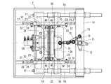
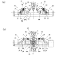
以下、図面を参照して、この発明による袋包装におけるしごき方法及び装置の実施の形態について説明する。図1は、この発明による袋包装におけるしごき装置の一例を示す平面図、図2は図1に示す袋包装におけるしごき装置の側面図であって、図2(a)はしごき装置が作動中である状態を、図2(b)はしごき装置が非作動中である状態を示している。 DESCRIPTION OF THE PREFERRED EMBODIMENTS Embodiments of the ironing method and apparatus for bag packaging according to the present invention will be described below with reference to the drawings. FIG. 1 is a plan view showing an example of the ironing device in the bag packaging according to the present invention, FIG. 2 is a side view of the ironing device in the bag packaging shown in FIG. 1, and FIG. FIG. 2 (b) shows a state where the ironing device is not operating.
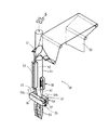
本実施例によるしごき装置は、周知の縦形製袋充填包装機に適用可能である。本実施例では、縦形製袋充填包装機自体は本発明の要部との直接の関連は希薄であるが、図4において概略を示すように、縦形製袋充填包装機50は、ウェブ状包装材60を曲成するフォーマ51と、フォーマ51の内部に挿通された製品充填筒52と、製品充填筒52の前側で曲成された包装材を筒状包装材61に成形する縦シール装置53と、製品充填筒52の左右両側を挟むように設けられており筒状包装材61を製品充填筒52の外側面との間に挟んで給送する送りベルト装置55と、製品充填筒52の下方に設けられたエンドシールユニット54とを備えている。被包装紙である連続するウェブ状の包装材60を、フォーマ51に導いて製品充填筒52を包むように筒状に曲成し、送りベルト装置55により下方へ連続して又は間欠して包装材の送りを行うとともに、製品充填筒52の一側で縦シール装置53によってウェブ端縁同士を縦ヒートシールすることによって筒状包装材61とし、製品充填筒52を通して落下充填される被包装物である製品Sの上下位置においてエンドシールユニット54によって筒状包装材61をエンドシールすることで、製品Sが包装された袋包装体63を連続して製造することができる。
The ironing apparatus according to the present embodiment can be applied to a well-known vertical bag making filling and packaging machine. In this embodiment, the vertical bag making filling and packaging machine itself is not directly related to the main part of the present invention, but as shown schematically in FIG. A former 51 that bends the
エンドシールユニット54は、カッタ56付きとすることができる。カッタ56は、例えば一方のエンドシール部54aにおいて、上下一対のヒートシールバー間に取り付けられており、他方のエンドシール部54bには、カッタ56に対応して、上下一対のヒートシールバー間にカッタ56が入り込むことができるカッタ溝57が形成されている。エンドシールユニット54の作動時に、エンドシール部54a,54bが筒状包装材61を挟み込んでヒートシールをするときに、カッタ56はカッタ溝57内に位置まで進入するので、筒状包装材61を切断し、先行して製造された袋包装体63を後続の袋62(筒状包装材61)から分離する。エンドシールユニット54の上方には、図示しないが、投入される製品Sを途中で一旦受け取り、且つエンドシール部54a,54bが離間するときに、受け止めた製品Sを解放して袋62の底部まで投入するシャッタを筒状包装材61に向かって突出する態様で設けることもできる。
The
図1及び図2に示すように、エンドシールユニット54は、筒状包装材61を挟んで対向して配置された一対のエンドシール部54a,54bを有するエンドシール手段であり、筒状包装材61から形成される袋63の開口端部に相当する部位に対して、単純に側方から接近・離間する形式のものを採用することができる。エンドシールユニット54を駆動するため、図示しない駆動モータ或いはエアシリンダのような駆動機構が用いられる。図示の例では、駆動機構の出力はエンドシール開閉レバー10の中央軸11に入力され、エンドシール開閉レバー10は、中央軸11の回りに回動される。エンドシール開閉レバー10の一方端にはカム作動子12が備わっており、カム作動子12は固定フレーム2に摺動案内されている横スライドブロック14に形成されているカム溝(図示せず)に嵌入されている。エンドシール開閉レバー10の他端部は枢支軸13によってリンク15に枢着されている。
As shown in FIGS. 1 and 2, the
横スライドブロック14には、その左右端部において、一対の案内シャフト16,16が取り付けられており、両案内シャフト16,16は横スライドブロック14のスライド移動と共にそのシャフト軸線方向に移動する。両案内シャフト16,16は、前後方向にシール位置C−Cを越えて反対側にまで延びており、それらの先端部には、取付け具17によってエンドシールユニット54に含まれる一方のエンドシールブロック18が取り付けられている。一方、エンドシール開閉レバー10の他端部に枢着されているリンク15は、その先端部において枢支軸19によって他方のエンドシールブロック20に連結されている。
A pair of
上記のエンドシールユニット54の構造によれば、駆動機構によってエンドシール開閉レバー10が中央軸11回りに回動するとき、リンク15を介してエンドシールブロック20を筒状包装材61に向かって進出・後退するとともに、横スライドブロック14、両案内シャフト16,16を介してエンドシールブロック18が筒状包装材61に向かって進出・後退される。エンドシールブロック18,20の移動量は同じに設定されているので、筒状包装材61はエンドシールブロック18,20にそれぞれ備わるエンドシール部54a,54bよって同期して各側から挟み込まれる。エンドシール部54a,54bは、互いに接近の際に筒状包装材61を挟み込んで、包装袋63の開口端部及び後続の包装袋の袋底端部にヒートシールを施す。
According to the structure of the
エンドシール手段としては、製品充填筒の略中心を通る一垂直面に関して前後に対称なおむすび円形のボックスモーションを行うものもあるが、この種のエンドシール手段は、おむすび円よりなるカム溝を有する板カムと、カム溝内を移動する遊動コロと、遊動コロと同軸のスライダーと、スライダーと係合するクランク等を必要としており、機構が複雑であって製造及びメンテナンスのコストが高いという難点がある。これに対して、本実施例のエンドシールユニット54は、構造が簡単であり、製造及びメンテナンスのコストを最小限のものに抑えることができる。
As an end seal means, there is one that performs a symmetrical box-shaped box motion back and forth with respect to one vertical plane passing through the approximate center of the product filling cylinder, but this type of end seal means has a cam groove made of a rice ball circle. It requires a plate cam, an idler roller that moves in the cam groove, a slider coaxial with the idler roller, a crank that engages with the slider, etc., and the mechanism is complicated and the manufacturing and maintenance costs are high. is there. On the other hand, the
しごき装置1は、エンドシールユニット54に関連して設けられており、筒状包装材61の各側にそれぞれ配設された一対のしごき部21,22(図2参照)から成っている。各しごき部21,22は、中間部にエンドシール部54a,54bに枢着された軸支部(支点ピン)24を有する左右一対のしごきアーム23,23、及び両しごきアーム23,23間に掛け渡されて包装袋の外側からしごき係合可能なしごきバー25を備えている。各しごきアーム23を回動可能に支持する軸支部(支点ピン)24は、エンドシールブロック18,20に取り付けられたしごきホルダ26に対して軸支されている。したがって、エンドシールユニット54が駆動機構によって駆動されるとき、エンドシールブロック18,20の前進・後退の動作に合わせて、しごきホルダ26及び軸支部24を介して、各しごきアーム23が作動する。
The ironing device 1 is provided in association with the
エンドシールユニット54のエンドシール動作の初期動作をしごき部21,22によるしごき動作に変換する変換機構としてのカム機構30が設けられている。カム機構30は、各しごきアーム23に関連して、しごきカム溝32が形成されているしごきカム板31、及びしごきアーム23の基端部、即ち、しごきバー25が設けられている先端部とは反対側の端部に設けられているカムフォロワ33を備えている。カムフォロワ33は、対応するしごきカム板31のしごきカム溝32に嵌入している。フレーム2には、図1に示すように、左右一対のカム板取付けレール36が前後方向に延びる態様で取り付けられている。左右前後の都合四つのしごきカム板31は、カム板取付けレール36に対して、カム溝32を内側に向ける状態で取り付けられている。カム溝32は、しごきアーム23に平行、即ち、筒状包装材61の給送方向とエンドシールユニッ54の接近・離間方向との二つの方向で定められる面と平行なしごきカム板31の板面内に、窪む態様で形成されている。なお、図2において、カム溝32の溝中心は一点鎖線で示されている。
A
各しごきカム溝32は、しごきアーム23が筒状包装際61に近づく動作をするときに、その位置に応じて、しごきバー25を包装袋の開口端部に接近させるとともに、開口端部を上側から下方へと擦るようにしごく動作をさせる形状に形成されている。即ち、しごきカム溝32は、図2(b)に示すように、しごきアーム23が後退した状態にあるときにカムフォロワ33が係合する後方の直線状の傾斜溝34と、しごきアーム23が前進するときにカムフォロワ33が係合する前方の急な湾曲溝35とから成っている。しごきアーム23の先端部としごきバー25との間には、しごき隙間調整ボルト40が設けられている(図1参照)。しごき隙間調整ボルト40は、しごき部21,22において、しごきバー25,25間の隙間を調整するためのボルトであって、手動でねじ込み量を加減することによって適宜に調整される。
Each ironing
次に、しごき装置1の作動について説明する。エンドシールユニット54が駆動機構の作動によってエンドシール動作を開始すると、エンドシール部54a,54bがリンク機構によって互いに同期して接近する。各しごきアーム23は、エンドシール部54a,54bに取り付けられているしごきホルダ26に枢着された軸支部24を介して、前進駆動される。各しごきアーム23の基端部に設けられているカムフォロワ33はしごきカム溝32に案内されるので、しごきアーム23の先端部に設けられているしごきバー25は、軸支部24の前進動作に合わせて、筒状包装材61(包装袋)のエンドシール予定位置を含めて、包装材を上方から下方へ向かってしごき動作をする。
Next, the operation of the ironing device 1 will be described. When the
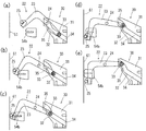
このしごき動作の詳細が、図3(a)〜(e)に段階的に示す説明図に示されている。図3には、筒状包装材61の一側に設けられたエンドシール部54bとしごき部22とが示されている。筒状包装材61の反対側でも、エンドシール部54aとしごき部21とが同期して対称的に作動しているが、これについては記載を省略する。
Details of the ironing operation are shown in the explanatory diagrams shown in steps in FIGS. 3 (a) to 3 (e). FIG. 3 shows the
図3(a)はエンドシール部54bが後退しており、しごき部22もしごき予定位置から上方に退避した位置にある。図3(b)は、(a)からエンドシール部54bがエンドシール動作を開始して僅かに前進した図であり、それに応じてしごき部22も前進するとともに、カムフォロワ33がしごきカム溝32の傾斜溝34に案内されつつ上昇することに応じて、しごきバー25がエンドシーラ部54bの高さ位置まで下がってきた状態を示している。この状態のときに、しごきバー25は、筒状包装材61から形成されている包装袋63のシール予定部分をしごく動作を開始する。
In FIG. 3A, the
図3(c)は、更に、エンドシール部54bが前進し、カムフォロワ33がしごきカム溝32の一層急峻な湾曲溝35に移行する。この時点以降、しごきバー25は、エンドシール部54aの前方位置を急速に降下してしごき動作を継続する。図3(d)は、図3(c)からの本格的なしごき動作を継続しているが、エンドシール部54bがヒートシールを行う高さ位置を経過しつつある状態を示している。図3(e)は、しごきバー25は、エンドシール部54bの下側位置まで下降し、しごき動作を完了した状態を示している。同時に、この状態では、エンドシール部54bは更に前進して、袋開口端部のヒートシールを実行開始している。
In FIG. 3C, the
図4には、既に説明したように、製袋充填包装装置が記載されている。しごきアーム23,23の一部が示されており、しごきバー25が互いに前進した状態であって且つしごき動作が完了した状態を示している。
In FIG. 4, as already described, a bag making filling and packaging apparatus is described. A part of the ironing
以上、説明したように、しごき部21,22において、しごきアーム23,23は左右のしごきカム板31,31によって、同期して案内される。エンドシールユニット54によるエンドシール動作の初期の段階において、その動作の一部を変換してしごきアーム23,23、しごきバー25,25が動作される。即ち、エンドシールユニット54のエンドシール動作の開始後に、しごき動作を開始し、実際にエンドシール動作が実行される前にしごき動作を終了するので、しごき動作を完了した後にエンドシール動作を開始する場合と比較して、包装サイクルを長くすることがない。
As described above, in the
この発明によるしごき装置は、縦型製袋充填包装機に適用された例を挙げて説明したが、必ずしも製袋充填包装に限定されるものではなく、基本的に縦型包装機全般に適用可能である。また、しごき部は袋の両サイドから係合するものとして説明したが、他方側を壁として一側からのみのしごき動作でも適用可能である。 The ironing device according to the present invention has been described with reference to an example applied to a vertical bag making filling packaging machine, but is not necessarily limited to bag making filling packaging, and is basically applicable to all vertical packaging machines. It is. Although the ironing portion has been described as engaging from both sides of the bag, the ironing operation can be applied only from one side with the other side as a wall.
1 しごき装置 2 固定フレーム
10 エンドシール開閉レバー 11 中央軸
12 カム作動子 13 枢支軸
14 横スライドブロック 15 リンク
16 案内シャフト 17 取付け具
18 エンドシールブロック 19 枢支軸
20 エンドシールブロック
21,22 しごき部 23 しごきアーム
24 軸支部(支点ピン) 25 しごきバー
26 しごきホルダ
30 カム機構 31 しごきカム板
32 しごきカム溝 33 カムフォロワ
34 傾斜溝 35 湾曲部
36 カム板取付けレール 40 しごき隙間調整ボルト
50 縦形製袋充填包装機 51 フォーマ
52 製品充填筒 53 縦シール装置
54 エンドシールユニット 54a,54b エンドシール部
55 送りベルト装置 56 カッタ
57 カッタ溝
60 ウェブ状包装材 61 筒状包装材
62 後続の袋 63 袋包装体
S 製品
DESCRIPTION OF SYMBOLS 1
Claims (5)
前記エンドシールユニットによる前記エンドシール動作は前記袋の前記開口端部への接近動作を含んでおり、
前記変換機構は、前記しごき動作を前記エンドシール動作の開始後に開始させ且つ前記エンドシールの実行前に終了させるため、前記エンドシールユニットによる前記接近動作を前記しごき手段による前記しごき動作に変換するカム機構から成り、
前記しごき手段は、前記エンドシールユニットの上部において枢着された軸支部を中間部に有する左右一対のしごきアーム、及び両しごきアームの先端部間に掛け渡されて包装袋の外側にしごき係合可能なしごきバーを備えており、
前記カム機構は、前記エンドシールユニットに対して前記接近動作の方向と反対方向後方において前記各しごきアームに対応して設けられており且つカム溝が形成されているしごきカム板、及び前記各しごきアームの基端部に設けられており前記カム溝に嵌入しているカムフォロワを備えており、前記エンドシールユニットが前記接近動作をすることによって生じる前記カム溝と前記カムフォロワとのカム作用により前記しごきアームを前記軸支部の回りに回動させて、前記接近動作をする前記エンドシールユニットの前方位置で前記しごきバーを降下させて前記しごき動作を行わせること
から成る袋包装におけるしごき装置。 An end seal unit that applies an end seal to an open end of a bag filled with a product, a means for squeezing the product from the outside of the bag, and a part of the end seal operation by the end seal unit for converting the squeezing means It has a conversion mechanism that converts it into a squeezing action
The end seal operation by the end seal unit includes an approach operation to the open end of the bag,
The conversion mechanism is a cam for converting the approaching operation by the end seal unit into the ironing operation by the ironing means in order to start the ironing operation after the start of the end seal operation and to end it before the end seal is executed. Consisting of mechanism,
The ironing means spans between a pair of left and right ironing arms having a shaft support portion pivotally attached to the upper portion of the end seal unit at an intermediate portion, and tip portions of both ironing arms, and irons the outer side of the packaging bag. It has a possible bar
The cam mechanism is provided corresponding to each ironing arm at the rear of the end seal unit in a direction opposite to the direction of the approaching operation, and an ironing cam plate in which a cam groove is formed, and each ironing A cam follower provided at a base end portion of the arm and fitted in the cam groove; and the ironing is effected by a cam action of the cam groove and the cam follower generated when the end seal unit performs the approaching operation. A squeezing device for bag packaging comprising rotating an arm around the shaft support and lowering the squeezing bar at a position in front of the end seal unit that performs the approaching operation to perform the squeezing operation .
から成る請求項1に記載の袋包装におけるしごき装置。 The both ironing arms have a shape in which the distal end portion is lowered at a front position of the end seal unit with respect to a horizontal posture taken by a portion connecting the shaft support portion from the base end portion when the ironing operation is finished. ironing device in the bag packaging according to claim 1 consisting of <br/> be formed in.
Priority Applications (1)
| Application Number | Priority Date | Filing Date | Title |
|---|---|---|---|
| JP2005187491A JP4792138B2 (en) | 2005-06-27 | 2005-06-27 | Ironing equipment for bag packaging |
Applications Claiming Priority (1)
| Application Number | Priority Date | Filing Date | Title |
|---|---|---|---|
| JP2005187491A JP4792138B2 (en) | 2005-06-27 | 2005-06-27 | Ironing equipment for bag packaging |
Publications (2)
| Publication Number | Publication Date |
|---|---|
| JP2007001654A JP2007001654A (en) | 2007-01-11 |
| JP4792138B2 true JP4792138B2 (en) | 2011-10-12 |
Family
ID=37687608
Family Applications (1)
| Application Number | Title | Priority Date | Filing Date |
|---|---|---|---|
| JP2005187491A Expired - Fee Related JP4792138B2 (en) | 2005-06-27 | 2005-06-27 | Ironing equipment for bag packaging |
Country Status (1)
| Country | Link |
|---|---|
| JP (1) | JP4792138B2 (en) |
Families Citing this family (9)
| Publication number | Priority date | Publication date | Assignee | Title |
|---|---|---|---|---|
| JP5253882B2 (en) * | 2008-05-23 | 2013-07-31 | 株式会社イシダ | Bag making and packaging machine |
| JP5331273B2 (en) * | 2008-12-26 | 2013-10-30 | 株式会社川島製作所 | Vertical packaging machine with squeezing equipment |
| JP5433231B2 (en) * | 2008-12-26 | 2014-03-05 | 株式会社川島製作所 | Vertical packaging machine with squeezing equipment |
| JP2011240958A (en) * | 2010-05-18 | 2011-12-01 | Sanko Kikai Kk | Lateral sealing device of automatic multiple line stick packing machine and automatic multiple line stick packing machine |
| MX387357B (en) * | 2017-02-23 | 2025-03-04 | Univ Iberoamericana A C | TUBULAR PLASTIC FILM PACKAGING SYSTEM. |
| CN110217427B (en) * | 2019-06-11 | 2024-07-16 | 邓旭辉 | Packaging adhesive bag sealing assembly for packaging machine |
| CN116573241B (en) * | 2023-05-10 | 2025-07-18 | 广东嘉威包装机械有限公司 | A packaging machine |
| CN118494842B (en) * | 2024-07-19 | 2024-09-13 | 常州强记机械制造有限公司 | Packaging equipment and preparation process of layered double hydroxide adsorbent |
| CN118953816B (en) * | 2024-10-17 | 2024-12-13 | 南通漫游通艺术包装有限公司 | A bag sealing device for packaging design |
Family Cites Families (2)
| Publication number | Priority date | Publication date | Assignee | Title |
|---|---|---|---|---|
| JP4636727B2 (en) * | 2001-04-27 | 2011-02-23 | 株式会社イシダ | Horizontal seal mechanism for bag making and packaging machine and bag making and packaging machine |
| JP2003011909A (en) * | 2001-07-02 | 2003-01-15 | Ishida Co Ltd | Bag making and packaging machine |
-
2005
- 2005-06-27 JP JP2005187491A patent/JP4792138B2/en not_active Expired - Fee Related
Also Published As
| Publication number | Publication date |
|---|---|
| JP2007001654A (en) | 2007-01-11 |
Similar Documents
| Publication | Publication Date | Title |
|---|---|---|
| US4040237A (en) | Sealing jaw mechanism for package making machine | |
| US4391081A (en) | Method of and apparatus for forming, filling and sealing packages | |
| JPH0613326B2 (en) | Packaging machine with variable sealing jaw moving device | |
| WO2005105578A1 (en) | Vertical filling-packaging machine and method of manufacturing packaging bag | |
| JP4792138B2 (en) | Ironing equipment for bag packaging | |
| CA3046978A1 (en) | Flexible jaws for vertical fill form and seal apparatus and methods of use | |
| US5014497A (en) | Method and apparatus for smoothing of bag making material in form, fill and seal machines | |
| JPH0339882B2 (en) | ||
| JP7121386B2 (en) | horizontal pillow packaging machine | |
| JP5260071B2 (en) | Bag making filling and packaging machine | |
| JP6970420B2 (en) | Packaging machine with toggle mechanism actuated seal unit | |
| JP6857958B2 (en) | Ironing device in vertical packaging machine | |
| JP5433231B2 (en) | Vertical packaging machine with squeezing equipment | |
| HK1247168B (en) | Twist packaging device | |
| JP2646514B2 (en) | Sealing device in filling and packaging machine | |
| JP5331273B2 (en) | Vertical packaging machine with squeezing equipment | |
| JP5297260B2 (en) | Vertical bag making filling and packaging machine with shutter device | |
| JP2849071B2 (en) | Seal bar type vertical automatic packaging machine | |
| JPH0676087B2 (en) | Ironing device for vertical bag filling and packaging machine | |
| JP7601373B2 (en) | Continuous motion vertical form fill seal machine | |
| JP4132940B2 (en) | Gusset packaging machine | |
| JP4488594B2 (en) | Powder packing and filling packaging method and packaging machine used for the packaging method | |
| JP2818402B2 (en) | Seal bar type vertical automatic packaging machine | |
| JP2001199402A (en) | Powder subdividing, filling and packaging method, and packaging machine therefor | |
| JP3916992B2 (en) | Bag making and packaging machine |
Legal Events
| Date | Code | Title | Description |
|---|---|---|---|
| A621 | Written request for application examination |
Free format text: JAPANESE INTERMEDIATE CODE: A621 Effective date: 20080625 |
|
| A977 | Report on retrieval |
Free format text: JAPANESE INTERMEDIATE CODE: A971007 Effective date: 20100907 |
|
| A131 | Notification of reasons for refusal |
Free format text: JAPANESE INTERMEDIATE CODE: A131 Effective date: 20101005 |
|
| A521 | Request for written amendment filed |
Free format text: JAPANESE INTERMEDIATE CODE: A523 Effective date: 20101206 |
|
| TRDD | Decision of grant or rejection written | ||
| A01 | Written decision to grant a patent or to grant a registration (utility model) |
Free format text: JAPANESE INTERMEDIATE CODE: A01 Effective date: 20110705 |
|
| A01 | Written decision to grant a patent or to grant a registration (utility model) |
Free format text: JAPANESE INTERMEDIATE CODE: A01 |
|
| A61 | First payment of annual fees (during grant procedure) |
Free format text: JAPANESE INTERMEDIATE CODE: A61 Effective date: 20110723 |
|
| FPAY | Renewal fee payment (event date is renewal date of database) |
Free format text: PAYMENT UNTIL: 20140729 Year of fee payment: 3 |
|
| R150 | Certificate of patent or registration of utility model |
Ref document number: 4792138 Country of ref document: JP Free format text: JAPANESE INTERMEDIATE CODE: R150 Free format text: JAPANESE INTERMEDIATE CODE: R150 |
|
| R250 | Receipt of annual fees |
Free format text: JAPANESE INTERMEDIATE CODE: R250 |
|
| R250 | Receipt of annual fees |
Free format text: JAPANESE INTERMEDIATE CODE: R250 |
|
| R250 | Receipt of annual fees |
Free format text: JAPANESE INTERMEDIATE CODE: R250 |
|
| LAPS | Cancellation because of no payment of annual fees |