JP4792000B2 - FPC connector - Google Patents
FPC connector Download PDFInfo
- Publication number
- JP4792000B2 JP4792000B2 JP2007114542A JP2007114542A JP4792000B2 JP 4792000 B2 JP4792000 B2 JP 4792000B2 JP 2007114542 A JP2007114542 A JP 2007114542A JP 2007114542 A JP2007114542 A JP 2007114542A JP 4792000 B2 JP4792000 B2 JP 4792000B2
- Authority
- JP
- Japan
- Prior art keywords
- fpc
- actuator
- connector
- dust cover
- auxiliary member
- Prior art date
- Legal status (The legal status is an assumption and is not a legal conclusion. Google has not performed a legal analysis and makes no representation as to the accuracy of the status listed.)
- Expired - Fee Related
Links
- 239000000428 dust Substances 0.000 claims description 62
- 239000000758 substrate Substances 0.000 claims description 44
- 238000003780 insertion Methods 0.000 claims description 20
- 230000037431 insertion Effects 0.000 claims description 20
- 230000009975 flexible effect Effects 0.000 description 9
- 238000005476 soldering Methods 0.000 description 6
- 239000002184 metal Substances 0.000 description 5
- 239000011810 insulating material Substances 0.000 description 4
- 229920003002 synthetic resin Polymers 0.000 description 4
- 239000000057 synthetic resin Substances 0.000 description 4
- 238000010079 rubber tapping Methods 0.000 description 3
- 230000014509 gene expression Effects 0.000 description 1
- 238000012986 modification Methods 0.000 description 1
- 230000004048 modification Effects 0.000 description 1
- 238000004080 punching Methods 0.000 description 1
- 229920005989 resin Polymers 0.000 description 1
- 239000011347 resin Substances 0.000 description 1
- 238000001179 sorption measurement Methods 0.000 description 1
Images

Landscapes
- Coupling Device And Connection With Printed Circuit (AREA)
- Connector Housings Or Holding Contact Members (AREA)
Description
本発明は、FPC用コネクタに関するものである。 The present invention relates to an FPC connector.
従来、フレキシブル回路基板、フレキシブルフラットケーブル等のFPCと称される可撓(とう)性を備える平板状ケーブルを接続するためのFPC用コネクタが提案されている。 2. Description of the Related Art Conventionally, FPC connectors have been proposed for connecting a flat cable having a flexible property called FPC, such as a flexible circuit board and a flexible flat cable.
そして、該FPC用コネクタは、FPCを挿入するための挿入口を備えるハウジングと、該ハウジングに並列して取付けられ、コンタクト片が前記挿入口から挿入されたFPCの面と対向して延在する複数個の端子と、前記挿入口から挿入されたFPCを前記端子のコンタクト片に向けて押圧するアクチュエータとを有する。該アクチュエータは、姿勢変化軸を中心として開位置と閉位置との間で姿勢変化可能となるようにハウジングに取付けられ、開位置にあるときに前記FPCのハウジングの挿入口への挿入及び取外しを可能とし、閉位置にあるときに前記FPCを端子のコンタクト片に向けて押圧して取外しを不能とするようになっている。 The FPC connector is mounted in parallel with a housing having an insertion port for inserting the FPC, and the contact piece extends to face the surface of the FPC inserted from the insertion port. A plurality of terminals, and an actuator that presses the FPC inserted from the insertion port toward a contact piece of the terminals. The actuator is attached to the housing so that the posture can be changed between an open position and a closed position about the posture change axis, and when the actuator is in the open position, the FPC is inserted into and removed from the insertion port of the housing. In the closed position, the FPC is pressed toward the contact piece of the terminal so that it cannot be removed.
しかし、前記FPC用コネクタは、基板に実装されて使用される場合に、端子と基板の配線との電気的接続部や端子のコンタクト片とFPCの接点との電気的接続部にカス、ダスト等の異物が進入して、隣接する端子同士や配線同士の間で短絡(ショートサーキット)が発生してしまうことがある。例えば、プラズマディスプレイテレビのような薄型ディスプレイ装置に使用される基板を薄型ディスプレイ装置の装置本体に固定する際には、前記基板をほぼ垂直な状態とし、タッピングビスを使用して装置本体にねじ止めするようになっている。ところが、タッピングビスによって基板の孔(あな)にFPCコネクタを固定する際、削りカスが発生する。この場合、前記基板にはFPC用コネクタが実装され、FPCが接続された状態となっている。そのため、前記削りカスが、特に、孔開けが行われる位置よりも下方において実装されているFPC用コネクタに降りかかり、該FPC用コネクタの端子と基板の配線との電気的接続部や端子のコンタクト片とFPCの接点との電気的接続部に進入し、隣接する端子同士や配線同士の間で短絡を引起こしてしまう。これにより、薄型ディスプレイ装置内の回路が電気的に破壊され、多額の損失が発生する。 However, when the FPC connector is used by being mounted on a substrate, the FPC connector may have an electrical connection between the terminal and the wiring of the substrate or an electrical connection between the contact piece of the terminal and the contact of the FPC. May enter, causing a short circuit (short circuit) between adjacent terminals or wires. For example, when fixing a substrate used in a thin display device such as a plasma display television to the device body of the thin display device, the substrate is set in a substantially vertical state and screwed to the device body using a tapping screw. It is supposed to be. However, when the FPC connector is fixed to the hole (hole) of the substrate with the tapping screw, scraps are generated. In this case, an FPC connector is mounted on the substrate, and the FPC is connected. For this reason, the shaving residue particularly falls on the FPC connector mounted below the position where the hole is to be drilled, and the electrical connection portion between the terminal of the FPC connector and the wiring of the board or the contact piece of the terminal And an electrical connection between the contact point of the FPC and a short circuit between adjacent terminals and wires. As a result, the circuit in the thin display device is electrically destroyed and a large loss occurs.
そこで、アクチュエータにダストカバー部を設け、アクチュエータを閉位置としたときにハウジングにおける挿入口と反対側の端部や端子のテール部がダストカバー部によって覆われるようにして、異物がFPC用コネクタの内部に進入することを防止するようにしたFPC用コネクタが提案されている(例えば、特許文献1参照。)。 Therefore, a dust cover is provided on the actuator, and when the actuator is in the closed position, the end of the housing opposite to the insertion port and the tail of the terminal are covered with the dust cover so that the foreign matter can be removed from the FPC connector. An FPC connector that prevents entry into the interior has been proposed (see, for example, Patent Document 1).
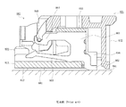
図10は従来のFPC用コネクタの断面図である。 FIG. 10 is a cross-sectional view of a conventional FPC connector.
図において、801は図示されないFPCを接続するためのFPC用コネクタであり、基板891に実装されている。ネイル881の下面が基板891の面上に形成された図示されない接続パッドにはんだ付によって接続され、端子861のテール部862が基板891の面上に形成された図示されない配線にはんだ付により接続されている。そして、端子861は、概略U字形状を有し、上腕ビーム864及び下腕ビーム863が端子受入溝834内において前方(図10における左方)に向って延在している。なお、端子861は、ハウジング811の下部812の上面及び上部815の下面によって、上下方向から挟まれて固定されている。
In the figure,
アクチュエータ821のストッパーピン848が上腕ビーム864の先端近傍に係合されている。そして、アクチュエータ821が、図10に示されるような閉位置にある状態になると、ダストカバー部822がハウジング811の後方、すなわち、挿入口833と反対側の端部及びテール部862を覆い隠す。そのため、ハウジング811の後方(図10における右方)から異物がFPC用コネクタ801の内部に進入することがないので、テール部862と基板891の配線との電気的接続部や、端子861とFPCの配線との電気的接続部に異物が進入することを防止することができる。そのため、異物によって隣接する端子861同士や配線同士が短絡することがない。
このように、前記従来のFPC用コネクタにおいては、前記アクチュエータ821を閉位置としたとき、アクチュエータ821と一体的に形成されたダストカバー部822が、異物がFPC用コネクタ801の内部に進入することを防止する。しかしながら、FPC用コネクタ801の各部材や基板891等の各部材の微少な歪みや寸法公差による部材間のばらつき、基板891への実装作業上の誤差等に起因してダストカバー部822と基板891との間に隙(すき)間が発生する場合がある。
Thus, in the conventional FPC connector, when the
本発明は、前記従来のFPC用コネクタの問題点を解決して、アクチュエータのダストカバー部にスライド可能な補助部材を取付けることによって、ダストカバー部とコネクタ実装表面との間に発生する隙間を塞(ふさ)ぎ、異物がFPC用コネクタの内部に進入することをより確実に防止することができ、隣接する端子同士や配線同士の間で短絡をより確実に防止し、信頼性を更に向上させることができるFPC用コネクタを提供することを目的とする。 The present invention solves the problems of the conventional FPC connector and attaches a slidable auxiliary member to the dust cover portion of the actuator, thereby closing the gap generated between the dust cover portion and the connector mounting surface. (Blockage), foreign matter can be more reliably prevented from entering the inside of the FPC connector, and short-circuiting between adjacent terminals and wires can be more reliably prevented, further improving reliability. An object of the present invention is to provide an FPC connector that can be used.
そのために、本発明のFPC用コネクタにおいては、FPCを挿入する挿入口を備えるハウジングと、該ハウジングに装填(てん)され、前記FPCの配線と電気的に接続するコンタクト片、及び、該コンタクト片を基板のコネクタ実装表面に接続するテール部を備える端子と、前記FPCを挿入可能な第1位置と挿入されたFPCを前記コンタクト片に押付ける第2位置との間を姿勢変化可能なアクチュエータとを有し、該アクチュエータは、前記第2位置において前記FPCを前記コンタクト片に押付ける押圧部、前記第2位置において前記テール部を覆うダストカバー部、前記押圧部と前記ダストカバー部とを一体的に形成する本体部、並びに、該ダストカバー部にスライド可能に取付けられた補助部材を備える。 Therefore, in the FPC connector of the present invention, a housing having an insertion port for inserting an FPC, a contact piece that is loaded into the housing and electrically connected to the wiring of the FPC, and the contact piece A terminal having a tail portion for connecting the FPC to the connector mounting surface of the board, and an actuator capable of changing the posture between a first position where the FPC can be inserted and a second position where the inserted FPC is pressed against the contact piece The actuator includes a pressing portion that presses the FPC against the contact piece in the second position, a dust cover portion that covers the tail portion in the second position, and the pressing portion and the dust cover portion are integrated. The main body part to be formed automatically, and an auxiliary member slidably attached to the dust cover part.
本発明の他のFPC用コネクタにおいては、さらに、前記補助部材は、前記第2位置において、前記ダストカバー部とコネクタ実装表面との間の隙間を塞ぐよう、前記ダストカバー部の端縁から突出するようスライド可能に取付けられる。 In another FPC connector of the present invention, the auxiliary member further protrudes from an edge of the dust cover portion so as to close a gap between the dust cover portion and the connector mounting surface in the second position. Mounted slidably to do.
本発明の更に他のFPC用コネクタにおいては、さらに、前記アクチュエータは、前記第2位置において前記補助部材をコネクタ実装表面に向けて前記ダストカバー部の端縁から突出するよう付勢する付勢部材を備える。 In still another FPC connector of the present invention, the actuator further biases the actuator so as to project the auxiliary member toward the connector mounting surface from the edge of the dust cover portion at the second position. Is provided.
本発明の更に他のFPC用コネクタにおいては、さらに、前記補助部材は、前記アクチュエータの幅方向に複数に分割され、分割された各部分が互いに独立してスライド可能である。 In still another FPC connector according to the present invention, the auxiliary member is further divided into a plurality in the width direction of the actuator, and the divided parts can slide independently of each other.
本発明によれば、FPC用コネクタは、アクチュエータのダストカバー部にスライド可能な補助部材が取付けられている。これにより、ダストカバー部とコネクタ実装表面との間に発生する隙間を塞ぎ、異物がFPC用コネクタの内部に進入することをより確実に防止することができ、隣接する端子同士や配線同士の間で短絡をより確実に防止し、信頼性を更に向上させることができる。 According to the present invention, the FPC connector has the auxiliary member slidable attached to the dust cover portion of the actuator. As a result, a gap generated between the dust cover part and the connector mounting surface can be blocked, and foreign matter can be more reliably prevented from entering the inside of the FPC connector. Therefore, the short circuit can be prevented more reliably and the reliability can be further improved.
以下、本発明の実施の形態について図面を参照しながら詳細に説明する。 Hereinafter, embodiments of the present invention will be described in detail with reference to the drawings.
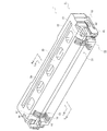
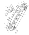
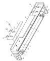
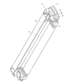
図1は本発明の実施の形態におけるコネクタを示す第1の斜視図でありアクチュエータが第2位置にあるときの斜め上後方から観た図、図2は本発明の実施の形態におけるコネクタを示す第2の斜視図でありアクチュエータが第2位置にあるときの斜め上前方から観た図、図3は本発明の実施の形態におけるコネクタを示す第3の斜視図でありアクチュエータが第1位置にあるときの斜め上前方から観た図、図4は本発明の実施の形態におけるコネクタのアクチュエータを示す斜視図であり斜め下後方から観た図、図5は本発明の実施の形態におけるコネクタのハウジングを示す斜視図であり斜め上前方から観た図である。 FIG. 1 is a first perspective view showing a connector according to an embodiment of the present invention. FIG. 1 is an oblique view from the upper rear when the actuator is in a second position, and FIG. 2 shows the connector according to the embodiment of the present invention. FIG. 3 is a second perspective view and is a view seen from obliquely upward and forward when the actuator is in the second position, and FIG. 3 is a third perspective view showing the connector in the embodiment of the present invention, and the actuator is in the first position. FIG. 4 is a perspective view showing the actuator of the connector in the embodiment of the present invention, FIG. 4 is a view seen from the oblique lower back, and FIG. 5 is a view of the connector in the embodiment of the present invention. It is the perspective view which shows a housing, and is the figure seen from diagonally upward front.
図において、1は本実施の形態におけるFPC用コネクタとしてのコネクタであり、平板状ケーブルを電気的に接続するためのコネクタとして使用される。前記平板状ケーブルは、フレキシブル回路基板(FPC:Flexible Printed Circuit)、フレキシブルフラットケーブル(FFC:Flexible Flat Cable)等と称される平板状可撓性ケーブルであるが、導電線を備える平板状のケーブルであれば、いかなる種類のものであってもよい。なお、本明細書においては、一般的にFPCと称されるフレキシブル回路基板だけでなく、FFCと称されるフレキシブルフラットケーブルをも含めた平板状可撓性ケーブル全般のことを「FPC」と言うこととする。 In the figure, reference numeral 1 denotes a connector as an FPC connector in the present embodiment, which is used as a connector for electrically connecting a flat cable. The flat cable is a flat flexible cable called a flexible printed circuit (FPC), a flexible flat cable (FFC), or the like, but a flat cable having a conductive wire. Any type may be used. In this specification, not only a flexible circuit board generally called FPC but also a flat flexible cable in general including a flexible flat cable called FFC is called “FPC”. I will do it.
また、本実施の形態において、コネクタ1の各部の構成及び動作を説明するために使用される上、下、左、右、前、後等の方向を示す表現は、絶対的なものでなく相対的なものであり、コネクタ1が図に示される姿勢である場合に適切であるが、コネクタ1の姿勢が変化した場合には姿勢の変化に応じて変更して解釈されるべきものである。 Further, in the present embodiment, expressions indicating directions such as upper, lower, left, right, front, rear, etc. used for explaining the configuration and operation of each part of the connector 1 are not absolute but relative. This is appropriate when the connector 1 is in the posture shown in the figure, but when the posture of the connector 1 is changed, it should be interpreted according to the change in the posture.
ここで、前記コネクタ1は、合成樹脂等の絶縁性材料によって一体的に形成されたハウジング11と、合成樹脂等の絶縁性材料によって一体的に形成され、前記ハウジング11に姿勢変化可能に取付けられたアクチュエータ21とを有する。すなわち、該アクチュエータ21は、姿勢変化して第1位置及び第2位置になるように前記ハウジング11に取付けられている。
Here, the connector 1 is integrally formed with an insulating material such as a synthetic resin and a
そして、該ハウジング11は、下部12、上部15、並びに、前記下部12と上部15との間に形成された前方(図2及び3における左斜め下方)から図示されないFPCの端部を挿入するための開口部である挿入口33を有し、該挿入口33には金属製の端子としての奇数極端子51及び偶数極端子61が装填される端子受入溝34が複数形成されている。該端子受入溝34は、例えば、ピッチ約0.5〔mm〕で70本程度形成され、各端子受入溝34には奇数極端子51及び偶数極端子61のいずれかが1つずつ装填されるようになっている。なお、必ずしもすべての端子受入溝34に端子が装填される必要はなく、FPCの配線の配列に対応させて、端子を適宜省略することができる。また、図においては、端子受入溝34及び端子が多数であるため、ハウジング11の両側近傍を除いて、前記端子受入溝34及び端子の図示が省略されている。
The
さらに、前記ハウジング11の両側部には、アクチュエータ21に形成された第1係合凸部29b、第2係合凸部29a及び係合当接部29とそれぞれ係合する第1係合凹部37b、第2係合凹部37a及び係合当接部36が形成されている。また、前記ハウジング11の前方(図2及び3における左斜め下方)寄りの両側下部には、金属製の取付補助金具としてのネイル81が取付けられている。そして、該ネイル81は金属板を加工したものであり、ハウジング11の中心方向に突出する係合突出部82を有する。
Further, on both sides of the
また、前記アクチュエータ21は、本体部23の前方(図4における左下方)寄りの部分における下面に、アクチュエータ21が第2位置としての閉位置になったときに、前記挿入口33から挿入されたFPCを下方、すなわち、前記端子受入溝34内に装填された奇数極端子51及び偶数極端子61の後述される下腕ビーム53及び63の方向に向けて押圧する複数の押圧部46を有する。また、該押圧部46はアクチュエータ21が開位置となったときにはFPCの挿入を可能にする。なお、前記押圧部46の間には、前記奇数極端子51及び偶数極端子61の後述される上腕ビーム54及び64を収容するための収容溝47が複数形成されている。該収容溝47の数及び位置は、前記端子受入溝34と対応する。また、前記本体部23は、アクチュエータ21が閉位置になったときに前記FPCの挿入方向とほぼ平行になり、アクチュエータ21が開位置になったときに前記FPCの挿入方向とほぼ直角になる。
In addition, the
そして、前記本体部23の後方(図4における右上方)端部には、アクチュエータ21が閉位置になったときに前記ハウジング11の後方(図5における右上方)、すなわち、前記挿入口33と反対側の端部及び奇数極端子51及び偶数極端子61の後述されるテール部52及び62を覆い隠すダストカバー部22が形成されている。該ダストカバー部22は、長方形で表面が平滑な平板状の実装用吸着エリア25、該実装用吸着エリア25の周囲を囲むように形成された凹部であるダストプール部26、該ダストプール部26の上端において後方に突出する指掛け部27を有する。なお、該指掛け部27は、アクチュエータ21が閉位置になったときにダストカバー部22の上縁に沿って実装用吸着エリア25の両側に位置するように形成されることが望ましい。これにより、オペレータが手指で操作して、第2位置としての閉位置にあるアクチュエータ21を第1位置としての開位置にまで姿勢変化させる際に、オペレータの手指を指掛け部27に容易に掛けることができ、前記アクチュエータ21を閉位置から開位置にまで容易に姿勢変化させることができる。
Further, at the rear (upper right in FIG. 4) end of the
さらに、前記ダストカバー部22にはスライド可能な補助部材41が取付けられている。該補助部材41は、合成樹脂等の絶縁性材料から成る板部材であり、アクチュエータ21が閉位置になったときに上下方向にスライドすることができるように、ダストプール部26に取付けられる。なお、図に示される例において、補助部材41は、左右に2分割されているが、左右一体に形成されていてもよいし、3分割以上に細かく分割されていてもよい。また、左右に分割された部分は、各々略L字状の形状を備え、左右の補助部材41を合せると、ダストプール部26と同様に、実装用吸着エリア25の周囲を囲むような形状を備えているが、いかなる形状を備えるものであってもよく、例えば、左右に延在する帯状の形状を備えるものであってもよい。
Further, a slidable
左右の補助部材41には、所定数(例えば、左右2つずつ)の係合開口42が形成され、該係合開口42がダストプール部26に所定数(例えば、左右2つずつ)形成された係合突起26aとスライド可能に係合するようになっている。この場合、前記係合開口42は上下に延在する細長い形状を備える。また、前記係合突起26aには、補助部材41を係止するための係止部材としての係止ピン45が固定される。該係止ピン45は、頭部の直径が係合開口42の幅よりも大きく、また、軸部が係合突起26aの中心に形成された挿入孔(こう)に圧入されて固定される。これにより、前記補助部材41は、ダストプール部26から脱落することなく、スライドすることができる。なお、補助部材41を係止するための係止部材は、前記係止ピン45に限定されるものでなく、例えば、頭部の直径が係合開口42の幅よりも大きなビスやボルトであってもよいし、係合開口42と係合突起26aとの係合状態を維持するものであれば、いかなる種類のものであってもよい。
The left and right
さらに、補助部材41の図4における上縁と指掛け部27との間には、補助部材41を図4における下方に付勢するための付勢部材43が配設される。該付勢部材43は、ばね性を備える部材であれば、いかなる部材であってもよく、例えば、コイルスプリングであってもよいし、リーフスプリングであってもよいし、また、補助部材41又は指掛け部27と一体的に形成されたものであってもよいし、補助部材41又は指掛け部27と別個に形成されたものであってもよい。図に示される例において、付勢部材43は、合成樹脂等の絶縁性材料から成る細長い棒状部材であり、ばね性を発揮するように、「へ」の字状、すなわち、ブーメラン状の形状に形成され、一端が補助部材41の上縁に一体的に接続されるとともに、他端が指掛け部27の下面に当接する。そして、付勢部材43は、図4における上下方向に圧縮されると、弾性的に変形してばね力を発揮し、これにより、補助部材41を下方に付勢する。
Furthermore, a biasing
また、前記本体部23には、開位置において前記FPCの挿入方向とほぼ平行な方向に貫通する貫通孔24が、複数個形成されている。該貫通孔24の形状、大きさ、数等は任意に設定することができるが、本実施の形態においては、5個形成されている。さらに、前記本体部23の両側部の内壁面には、前記ハウジング11の第1係合凹部37b、第2係合凹部37aと係合する第1係合凸部29b及び第2係合凸部29aが形成され、前記本体部23の前方(図2における左下方)端部の両側部には、前記ハウジング11の係合当接部36と係合する係合当接部29が形成されている。また、前記本体部23の両側部の外壁面には、前記ネイル81の係合突出部82と係合する第3係合凸部28a及び第4係合凸部28bが形成されている。
The
そして、コネクタ1は、図1に示されるように、コネクタ実装表面としての基板91の面上に実装される。なお、前記基板91は、例えば、プリント回路基板であるが、コネクタ1を実装可能な部材であれば、いかなる部材であってもよい。この場合、前記ネイル81の下面が前記基板91の面上に形成された接続パッドにはんだ付によって接続され、また、前記奇数極端子51及び偶数極端子61の後端に突出するテール部52及び62が前記基板91の面上に形成された配線にはんだ付によって接続される。これにより、ハウジング11が前記基板91の面上に固定されるとともに、奇数極端子51及び偶数極端子61のそれぞれが対応する配線に電気的に接続されて電気的接続部を形成する。
And the connector 1 is mounted on the surface of the board |
次に、前記構成のコネクタ1の動作について説明する。 Next, the operation of the connector 1 having the above configuration will be described.
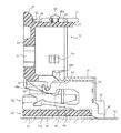
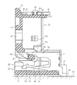
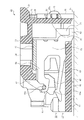
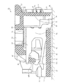
図6は本発明の実施の形態におけるアクチュエータが第1位置にあるときのコネクタの内部を示す第1の断面図であり図3のA−A矢視断面図、図7は本発明の実施の形態におけるアクチュエータが第1位置にあるときのコネクタの内部を示す第2の断面図であり図3のB−B矢視断面図、図8は本発明の実施の形態におけるアクチュエータが第2位置にあるときのコネクタの内部を示す第1の断面図であり図2のC−C矢視断面図、図9は本発明の実施の形態におけるアクチュエータが第2位置にあるときのコネクタの内部を示す第2の断面図であり図2のD−D矢視断面図である。 6 is a first cross-sectional view showing the inside of the connector when the actuator according to the embodiment of the present invention is in the first position. FIG. 6 is a cross-sectional view taken along the line AA in FIG. 3, and FIG. FIG. 8 is a second cross-sectional view showing the inside of the connector when the actuator in the embodiment is in the first position, and is a cross-sectional view taken along the line B-B in FIG. 3, and FIG. 8 is the actuator in the second position in the embodiment of the present invention; FIG. 9 is a first cross-sectional view showing the inside of the connector at a certain time, a cross-sectional view taken along the line CC in FIG. 2, and FIG. 9 shows the inside of the connector when the actuator according to the embodiment of the present invention is in the second position. FIG. 3 is a second cross-sectional view and a cross-sectional view taken along the line DD in FIG. 2.
本実施の形態において、端子は金属板を打抜くことによって形成され、2種類の形状のものが使用され、ハウジング11には、2種類の形状の端子がハウジング11の幅方向に交互に配列されるように装填される。ここでは、奇数番目に配列される端子を奇数極端子51(第1の端子)として説明し、偶数番目に配列される端子を偶数極端子61(第2の端子)として説明する。
In the present embodiment, the terminals are formed by punching a metal plate, and two types of shapes are used. In the
図6及び8は、偶数極端子61が装填されている部分の断面図である。なお、ネイル81の下面が基板91の面上に形成された図示されない接続パッドにはんだ付によって接続され、テール部62が前記基板91の面上に形成された図示されない配線にはんだ付により接続された状態が示されている。そして、偶数極端子61は、概略U字形状を有し、上腕ビーム64及び下腕ビーム63が端子受入溝34内において前方(図6及び8における左方)に向って延在している。なお、前記偶数極端子61は、ハウジング11の後方(図6及び8における右方)から端子受入溝34内に挿入され、該端子受入溝34の床面及び天井面を構成する下部12の上面及び上部15の下面によって、上下方向から挟まれて固定されている。
6 and 8 are cross-sectional views of the portion where the
ここで、前記下腕ビーム63は、図示されないFPCの配線と電気的に接続するコンタクト片として機能するものであり、その先端(図6及び8における左端)近傍には上方に突出するコンタクト部63aが形成されている。なお、前記FPCは、配線が表面に露出した面が下方を向くようにしてハウジング11の挿入口33に挿入されるものとする。
Here, the
また、前記上腕ビーム64の先端近傍には、上向きに開放する凹状のストッパーピン係合部65が形成されている。そして、アクチュエータ21の軸部材としてのストッパーピン48aが前記ストッパーピン係合部65内を移動可能となっている。なお、偶数番目の端子受入溝34に対応するアクチュエータ21の収容溝47に配設されたストッパーピン48aは、断面が円形となっている。
A concave stopper
一方、図7及び9は、奇数極端子51が装填されている部分の断面図である。奇数極端子51は、概略U字形状を有し、上腕ビーム54及び下腕ビーム53が端子受入溝34内において前方(図7及び9における左方)に向って延在している。なお、奇数極端子51も、前記偶数極端子61と同様に、ハウジング11の後方(図7及び9における右方)から端子受入溝34内に挿入され、該端子受入溝34の床面及び天井面を構成する下部12の上面及び上部15の下面によって、上下方向から挟まれて固定されている。
On the other hand, FIGS. 7 and 9 are sectional views of a portion where the odd-numbered
ここで、前記下腕ビーム53は、図示されないFPCの配線と電気的に接続するコンタクト片として機能するものであり、その先端(図7及び9における左端)近傍には上方に突出するコンタクト部53aが形成されている。
Here, the
また、前記上腕ビーム54の先端近傍には、下端が直線状のカム受け部55が形成されている。そして、アクチュエータ21が、図9に示されるような閉位置にある状態になると、前記カム受け部55の下端にアクチュエータ21の軸部材としてのカム48bの直線状の縁が当接して係合するようになっている。なお、奇数番目の端子受入溝34に対応するアクチュエータ21の収容溝47に配設されたカム48bは、断面が不定形であり、アクチュエータ21が閉位置にあるときに上方に位置する直線状の縁を備えている。なお、図7に示されるように、アクチュエータ21が第1位置としての開位置にある状態において、カム受け部55とカム48bとは非接触となっている。
Further, a
さらに、アクチュエータ21が開位置にある状態においては、アクチュエータ21の係合当接部29がハウジング11の係合当接部36に当接して係合した状態になっている。そのため、前記アクチュエータ21は、振動等による不測の外力が付与されても、また、オペレータの手指による操作力が付与されても、開位置から図6及び7における反時計回り方向に姿勢変化することがない。
Further, when the
また、アクチュエータ21が開位置にある状態においては、アクチュエータ21の第1係合凸部29bがハウジング11の第1係合凹部37bに当接して係合した状態になっている。そのため、前記アクチュエータ21は、振動等による不測の外力が付与されても、開位置から図6及び7における時計回り方向に姿勢変化することがない。しかし、前記第1係合凸部29bにおいて第1係合凹部37bと当接する下側の側面は傾斜側面となっていて、かつ、前記第1係合凹部37bにおいて第1係合凸部29bと当接する上側の側面は傾斜側面となっているので、オペレータの手指による操作力程度の強い力が付与された場合には、第1係合凸部29bと第1係合凹部37bとの係合が解除される。
Further, when the
このように、開位置にあるとき、アクチュエータ21のハウジング11に対する姿勢は、安定しており、振動等による不測の外力が付与されても変化することがない。しかし、オペレータの手指による操作力程度の強い力が付与されると、閉位置に向けて姿勢変化するようになっている。すなわち、アクチュエータ21は、開位置にあるとき、オペレータによる操作が行われない限り、振動等による不測の外力が付与されても、閉位置への姿勢変化が防止される。
Thus, when in the open position, the posture of the
また、開位置にあるとき、アクチュエータ21のハウジング11に対する姿勢が安定しているので、コネクタ1を実装する際に、ロボットアーム等の先端に装着された図示されない真空吸着ノズルによって実装用吸着エリア25を上方から下向きに押付けても、アクチュエータ21が姿勢変化してしまうことがない。そのため、ロボットアーム等を備える通常の実装装置を使用して、コネクタ1を搬送し、さらに、コネクタ1を基板91に対して仮固定することができる。
Further, since the posture of the
そして、図6及び7に示されるように、アクチュエータ21が第1位置としての開位置にある状態において、FPCがハウジング11の挿入口33に挿入される。
6 and 7, the FPC is inserted into the
続いて、オペレータが前記アクチュエータ21を時計回り方向に姿勢変化させ、図8及び9に示されるような第2位置としての閉位置にある状態とする。これにより、押圧部46が回転し、その押圧面が下方向に移動し、図示されないFPCの上面に当接して下方に向いた力を付与し、FPCを奇数極端子51及び偶数極端子61のコンタクト片としての下腕ビーム53及び63に押付ける。これにより、前記FPCの下側の表面において露出している配線が、表面に露出した面をコンタクト部53a及び63aに当接して電気的接続部が形成され、FPCの配線と奇数極端子51及び偶数極端子61とが電気的に接続される。
Subsequently, the operator changes the posture of the
また、アクチュエータ21を開位置から閉位置にすると、カム48bの直線状の縁が奇数極端子51のカム受け部55の下端に当接して係合するので、アクチュエータ21のそれ以上の姿勢の変化を急激に停止させる。そのため、前記オペレータに確かなクリック感を与えることができ、FPCの配線と端子とが電気的に接続されたことを前記オペレータに認識させることができる。
Further, when the
このように、前記アクチュエータ21が、図8及び9に示されるような第2位置としての閉位置にある状態になると、ダストカバー部22がハウジング11の後方、すなわち、挿入口33と反対側の端部及び奇数極端子51及び偶数極端子61のテール部52及び62を覆い隠す。そのため、ハウジング11の後方から異物がコネクタ1の内部に進入することがないので、テール部52及び62と基板91の配線との電気的接続部や、コンタクト部53a及び63aとFPCの配線との電気的接続部に異物が進入することを防止することができる。そのため、異物によって隣接する端子同士や配線同士が短絡することがない。
Thus, when the
特に、基板91を、図8及び9に示されるような水平な状態でなく、垂直な状態に配置して前記ハウジング11の後方が上を向くようにした場合、空気中のダスト等の異物が落下してきても、前記ダストカバー部22によって異物の進入を防止することができる。また、前記「背景技術」の項において説明したように、基板91を垂直な状態としてタッピングビスを使用してねじ止めすると削りカスが発生し、該削りカスがコネクタ1にハウジング11の後方から、すなわち、上方から降りかかることが考えられるが、このような場合であっても、前記ダストカバー部22によって削りカス等の異物の進入を防止することができる。
In particular, when the
なお、前記「発明が解決しようとする課題」の項において説明したように、コネクタ1の有する各部材の寸法公差、コネクタ1を基板91に実装する作業における作業上の誤差、基板91の歪(ゆが)み等に起因して、ダストカバー部22と基板91の表面との間にわずかな隙間が生ずる場合がある。しかし、本実施の形態においては、ダストカバー部22にスライド可能な補助部材41が取付けられているので、図8及び9に示されるように、ダストカバー部22と基板91の表面との間の隙間が補助部材41によって塞がれる。そのため、微小な異物が前記隙間からコネクタ1内に進入することも確実に防止される。
As described in the above section “Problems to be Solved by the Invention”, the dimensional tolerance of each member of the connector 1, work errors in mounting the connector 1 on the
ここで、補助部材41と指掛け部27との間には付勢部材43が配設され、前記補助部材41は、図6及び7に示されるような自由にスライド可能な状態においては、前記付勢部材43によって指掛け部27から離れる方向(図6及び7における右方向)に付勢され、その指掛け部27と反対側の端縁41aがダストカバー部22の端縁22aから突出している。前記付勢部材43の端縁41aがダストカバー部22の端縁22aから突出する突出量は、例えば、係合開口42の位置や大きさを調整することによって任意に調整することができる量であり、前記隙間の予想最大値以上となるように調整されることが望ましい。
Here, an urging
この場合、アクチュエータ21が、図8及び9に示されるような閉位置にある状態になると、補助部材41の端縁41a、すなわち、閉位置での下端縁が基板91の表面に当接し、前記隙間は補助部材41によって塞がれる。なお、前記下端縁の突出量が前記隙間の予想最大値以上なので、補助部材41は、前記下端縁が基板91の表面に当接することによって、指掛け部27に接近する方向、すなわち、閉位置での上方向にスライドする。すると、付勢部材43は、図8及び9における上下方向に圧縮され、弾性的に変形してばね力を発揮し、補助部材41を下方、すなわち、コネクタ実装表面に向けて付勢する。そのため、前記下端縁が基板91の表面に押圧された状態となり、前記下端縁と基板91の表面との間は常に閉止された状態となる。したがって、前記隙間は、補助部材41によって確実に塞がれる。
In this case, when the
このとき、付勢に要する力は樹脂等で作られた軽量の補助部材41を押す力だけで良く、例えば、コネクタ1を逆さまの状態にしたときに補助部材41が自重で移動しない程度かそれより少し強いものとする。こうすれば、アクチュエータ21を第2の位置にして補助部材41が付勢され、基板91を押圧してもその反力がアクチュエータ21の動作に影響することはない。
At this time, the force required for urging is only a force for pressing the lightweight
なお、該補助部材41は、アクチュエータ21の幅方向に複数に分割され、分割された各部が互いに独立してスライドすることができる。そのため、前記隙間の大きさがアクチュエータ21の幅方向に均一でない場合であっても、すなわち、前記隙間の大きさがアクチュエータ21の幅方向に関して変化していても、補助部材41の各々のスライド量が前記隙間の大きさに対応して変化するので、前記隙間を確実に塞ぐことが可能となる。この分割数が多いと、部品点数が多くなるが、基板91の歪み等の変化によって追従可能となり、隙間を塞ぐ作用がより確実となる。
The
さらに、前述したように、ダストカバー部22は凹状の部分であるダストプール部26を有する。そして、基板91を垂直な状態とすると、前記ダストプール部26が上を向いた状態となる。そのため、上方から降りかかってきた削りカス等の異物は、前記ダストプール部26内に収容される。さらに、該ダストプール部26が凹状の部分であるので、ダストプール部26内に収容された異物は、ダストプール部26の外へこぼれ出ることがない。そのため、前記ダストカバー部22によってコネクタ1への進入を防止された異物が拡散して他の電気的接続部に進入することも防止することができる。
Furthermore, as described above, the
また、アクチュエータ21が閉位置にあるとき、アクチュエータ21の第2係合凸部29aがハウジング11の第2係合凹部37aに当接して係合した状態になっている。そのため、前記アクチュエータ21は、振動等による不測の外力が付与されても、閉位置から図8及び9における反時計回り方向に姿勢変化することがない。しかし、前記第2係合凸部29aにおいて第2係合凹部37aと当接する上側の側面は傾斜側面となっていて、かつ、前記第2係合凹部37aにおいて第2係合凸部29aと当接する下側の側面は傾斜側面となっているので、オペレータの手指による操作力程度の強い力が付与された場合には、第2係合凸部29aと第2係合凹部37aとの係合が解除される。
When the
このように、閉位置にあるとき、アクチュエータ21のハウジング11に対する姿勢は、安定しており、振動等による不測の外力が付与されても変化することがない。しかし、オペレータの手指による操作力程度の強い力が付与されると、開位置に向けて姿勢変化するようになっている。すなわち、アクチュエータ21は、FPCが接続されて閉位置にあるとき、オペレータによる操作が行われない限り、振動等による不測の外力が付与されても、開位置への姿勢変化が防止されるので、FPCの接続が外れる恐れがない。
Thus, when in the closed position, the posture of the
このように、本実施の形態において、アクチュエータ21は、閉位置になったときにハウジング11の後方端部及びテール部52及び62を覆い隠すダストカバー部22を備えるとともに、該ダストカバー部22にスライド可能な補助部材41が取付けられている。
As described above, in the present embodiment, the
そのため、ダストカバー部22と基板91との間に発生する隙間も補助部材41によって塞がれるので、ハウジング11の後方から異物がコネクタ1の内部に進入することが確実に防止される。したがって、テール部52及び62と基板91の配線との電気的接続部や、コンタクト部53a及び63aとFPCの配線との電気的接続部に異物が進入することを確実に防止することができ、異物によって隣接する端子同士や配線同士が短絡することがない。
For this reason, the gap generated between the
特に、基板91を垂直な状態に配置して前記ハウジング11の後方が上を向くようにした場合であっても、前記ダストカバー部22によって異物の進入を防止することができる。
In particular, even when the
また、補助部材41は、閉位置においてFPCの挿入方向とほぼ直交する方向にスライドし、ダストカバー部22と基板91の表面との間の隙間を塞ぐようになっている。そのため、微小な異物が前記隙間からコネクタ1内に進入することも確実に防止される。
In addition, the
さらに、アクチュエータ21は、閉位置において補助部材41を基板91の表面に向けて付勢する付勢部材43を備える。そのため、補助部材41が基板91の表面に押圧された状態となり、前記補助部材41と基板91の表面との間は常に閉止された状態となるので、ダストカバー部22と基板91の表面との間の隙間は、補助部材41によって確実に塞がれる。
Further, the
さらに、補助部材41は、アクチュエータ21の幅方向に複数に分割され、分割された各部分が互いに独立してスライド可能である。そのため、ダストカバー部22と基板91の表面との間の隙間の大きさがアクチュエータ21の幅方向に均一でない場合であっても、補助部材41の各々のスライド量が前記隙間の大きさに対応して変化するので、前記隙間を確実に塞ぐことが可能となる。
Furthermore, the
なお、本実施の形態においては、補助部材41がダストカバー部22の外側、すなわち、図6及び7におけるダストカバー部22の上面側に取付けられている例についてのみ説明したが、前記補助部材41は、ダストカバー部22の内側、すなわち、図6及び7におけるダストカバー部22の下面側に取付けられていてもよい。この場合、前述のように、基板91を垂直な状態とすると、上を向いたダストプール部26上に補助部材41が存在しなくなるので、ダストプール部26の面積が増大したのと同様になる。そのため、ダストプール部26内により多量の異物を収容することができ、異物がダストプール部26の外へこぼれ出ることをより確実に防止することができる。
In the present embodiment, only the example in which the
また、本発明は前記実施の形態に限定されるものではなく、本発明の趣旨に基づいて種々変形させることが可能であり、それらを本発明の範囲から排除するものではない。 The present invention is not limited to the above-described embodiment, and various modifications can be made based on the spirit of the present invention, and they are not excluded from the scope of the present invention.
1 コネクタ
11、811 ハウジング
12、812 下部
15、815 上部
21、821 アクチュエータ
22、822 ダストカバー部
22a、41a 端縁
23 本体部
24 貫通孔
25 実装用吸着エリア
26 ダストプール部
26a 係合突起
27 指掛け部
28a 第3係合凸部
28b 第4係合凸部
29、36 係合当接部
29a 第2係合凸部
29b 第1係合凸部
33、833 挿入口
34、834 端子受入溝
37a 第2係合凹部
37b 第1係合凹部
41 補助部材
42 係合開口
43 付勢部材
45 係止ピン
46 押圧部
47 収容溝
48a、848 ストッパーピン
48b カム
51 奇数極端子
52、62、862 テール部
53、63、863 下腕ビーム
53a、63a コンタクト部
55 カム受け部
54、64、864 上腕ビーム
61 偶数極端子
65 ストッパーピン係合部
81、881 ネイル
82 係合突出部
91、891 基板
801 FPC用コネクタ
861 端子
1
Claims (4)
(b)該ハウジング(11)に装填され、前記FPCの配線と電気的に接続するコンタクト片(53、63)、及び、該コンタクト片(53、63)を基板(91)のコネクタ実装表面に接続するテール部(52、62)を備える端子(51、61)と、
(c)前記FPCを挿入可能な第1位置と挿入されたFPCを前記コンタクト片(53、63)に押付ける第2位置との間を姿勢変化可能なアクチュエータ(21)とを有するFPC用コネクタ(1)であって、
(d)前記アクチュエータ(21)は、前記第2位置において前記FPCを前記コンタクト片(53、63)に押付ける押圧部(46)、前記第2位置において前記テール部(52、62)を覆うダストカバー部(22)、前記押圧部(46)と前記ダストカバー部(22)とを一体的に形成する本体部(23)、並びに、前記ダストカバー部(22)にスライド可能に取付けられた補助部材(41)を備えることを特徴とするFPC用コネクタ(1)。 (A) a housing (11) including an insertion port (33) for inserting an FPC;
(B) Contact pieces (53, 63) loaded in the housing (11) and electrically connected to the wiring of the FPC, and the contact pieces (53, 63) on the connector mounting surface of the substrate (91) Terminals (51, 61) having tail portions (52, 62) to be connected;
(C) FPC connector having an actuator (21) whose posture can be changed between a first position where the FPC can be inserted and a second position where the inserted FPC is pressed against the contact pieces (53, 63). (1)
(D) The actuator (21) covers the pressing portion (46) that presses the FPC against the contact pieces (53, 63) in the second position, and the tail portion (52, 62) in the second position. A dust cover part (22), a body part (23) integrally forming the pressing part (46) and the dust cover part (22), and a slidably attached to the dust cover part (22) An FPC connector (1) comprising an auxiliary member (41).
Priority Applications (1)
| Application Number | Priority Date | Filing Date | Title |
|---|---|---|---|
| JP2007114542A JP4792000B2 (en) | 2007-04-24 | 2007-04-24 | FPC connector |
Applications Claiming Priority (1)
| Application Number | Priority Date | Filing Date | Title |
|---|---|---|---|
| JP2007114542A JP4792000B2 (en) | 2007-04-24 | 2007-04-24 | FPC connector |
Publications (2)
| Publication Number | Publication Date |
|---|---|
| JP2008270087A JP2008270087A (en) | 2008-11-06 |
| JP4792000B2 true JP4792000B2 (en) | 2011-10-12 |
Family
ID=40049315
Family Applications (1)
| Application Number | Title | Priority Date | Filing Date |
|---|---|---|---|
| JP2007114542A Expired - Fee Related JP4792000B2 (en) | 2007-04-24 | 2007-04-24 | FPC connector |
Country Status (1)
| Country | Link |
|---|---|
| JP (1) | JP4792000B2 (en) |
Families Citing this family (2)
| Publication number | Priority date | Publication date | Assignee | Title |
|---|---|---|---|---|
| JP5530953B2 (en) * | 2011-02-18 | 2014-06-25 | 京セラコネクタプロダクツ株式会社 | connector |
| JP7094636B2 (en) * | 2019-07-24 | 2022-07-04 | 矢崎総業株式会社 | connector |
-
2007
- 2007-04-24 JP JP2007114542A patent/JP4792000B2/en not_active Expired - Fee Related
Also Published As
| Publication number | Publication date |
|---|---|
| JP2008270087A (en) | 2008-11-06 |
Similar Documents
| Publication | Publication Date | Title |
|---|---|---|
| JP4098290B2 (en) | FFC connector | |
| US10651581B1 (en) | Connector | |
| US8613631B2 (en) | Electrical connector | |
| US7497697B2 (en) | PCB connector including plug and socket contacts for easy positioning | |
| JP6325720B1 (en) | Multi-contact connector | |
| US20080108237A1 (en) | Ball grid array socket having a positioning device | |
| US8113887B2 (en) | Card connector and electronic apparatus including the same | |
| JP2012079684A (en) | Connector for substrates | |
| JP6462634B2 (en) | connector | |
| JP4031471B2 (en) | FPC connector | |
| CN114303288B (en) | Connectors and Electronic Devices | |
| US9252516B2 (en) | Connector | |
| CN115377719A (en) | Terminal, wire connector and wire-to-board connector | |
| CN101529661A (en) | Connector | |
| JP4792000B2 (en) | FPC connector | |
| JP5275781B2 (en) | Electrical connection terminal and connector using the same | |
| JP7038597B2 (en) | Connectors and electronic devices | |
| US9899782B2 (en) | Connector assembly and connector assembly mounted structure | |
| CN114270632B (en) | Connectors and Electronic Devices | |
| US11309652B2 (en) | Contact for electrically connecting a first member and a second member using spring part | |
| US9755339B2 (en) | Connecting structure of connector and flat circuit body | |
| JP2007287420A (en) | Connector for cable connection | |
| JP2008288004A (en) | Connector for cable | |
| CN111541071B (en) | Connector assembly | |
| CN114600321B (en) | Connector |
Legal Events
| Date | Code | Title | Description |
|---|---|---|---|
| A621 | Written request for application examination |
Free format text: JAPANESE INTERMEDIATE CODE: A621 Effective date: 20091214 |
|
| A977 | Report on retrieval |
Free format text: JAPANESE INTERMEDIATE CODE: A971007 Effective date: 20110614 |
|
| TRDD | Decision of grant or rejection written | ||
| A01 | Written decision to grant a patent or to grant a registration (utility model) |
Free format text: JAPANESE INTERMEDIATE CODE: A01 Effective date: 20110628 |
|
| A01 | Written decision to grant a patent or to grant a registration (utility model) |
Free format text: JAPANESE INTERMEDIATE CODE: A01 |
|
| A61 | First payment of annual fees (during grant procedure) |
Free format text: JAPANESE INTERMEDIATE CODE: A61 Effective date: 20110722 |
|
| FPAY | Renewal fee payment (event date is renewal date of database) |
Free format text: PAYMENT UNTIL: 20140729 Year of fee payment: 3 |
|
| R150 | Certificate of patent or registration of utility model |
Free format text: JAPANESE INTERMEDIATE CODE: R150 |
|
| R250 | Receipt of annual fees |
Free format text: JAPANESE INTERMEDIATE CODE: R250 |
|
| LAPS | Cancellation because of no payment of annual fees |