JP4789928B2 - Surgical knife blade mounting apparatus and method of using the apparatus - Google Patents
Surgical knife blade mounting apparatus and method of using the apparatus Download PDFInfo
- Publication number
- JP4789928B2 JP4789928B2 JP2007510798A JP2007510798A JP4789928B2 JP 4789928 B2 JP4789928 B2 JP 4789928B2 JP 2007510798 A JP2007510798 A JP 2007510798A JP 2007510798 A JP2007510798 A JP 2007510798A JP 4789928 B2 JP4789928 B2 JP 4789928B2
- Authority
- JP
- Japan
- Prior art keywords
- blade
- cap
- receiving port
- inclined portion
- fixing
- Prior art date
- Legal status (The legal status is an assumption and is not a legal conclusion. Google has not performed a legal analysis and makes no representation as to the accuracy of the status listed.)
- Expired - Fee Related
Links
- 238000000034 method Methods 0.000 title description 26
- 238000001356 surgical procedure Methods 0.000 description 5
- 208000002177 Cataract Diseases 0.000 description 3
- 230000009471 action Effects 0.000 description 3
- 210000004087 cornea Anatomy 0.000 description 3
- 238000007689 inspection Methods 0.000 description 3
- 230000007423 decrease Effects 0.000 description 2
- 230000004048 modification Effects 0.000 description 2
- 238000012986 modification Methods 0.000 description 2
- 239000004593 Epoxy Substances 0.000 description 1
- 230000001154 acute effect Effects 0.000 description 1
- 239000000853 adhesive Substances 0.000 description 1
- 230000001070 adhesive effect Effects 0.000 description 1
- 238000004873 anchoring Methods 0.000 description 1
- 210000000234 capsid Anatomy 0.000 description 1
- 238000006243 chemical reaction Methods 0.000 description 1
- 150000001875 compounds Chemical class 0.000 description 1
- 239000000356 contaminant Substances 0.000 description 1
- 230000008878 coupling Effects 0.000 description 1
- 238000010168 coupling process Methods 0.000 description 1
- 238000005859 coupling reaction Methods 0.000 description 1
- 230000003247 decreasing effect Effects 0.000 description 1
- 238000006073 displacement reaction Methods 0.000 description 1
- 125000003700 epoxy group Chemical group 0.000 description 1
- 230000036541 health Effects 0.000 description 1
- 239000007943 implant Substances 0.000 description 1
- 238000009434 installation Methods 0.000 description 1
- 239000013618 particulate matter Substances 0.000 description 1
- 229920000647 polyepoxide Polymers 0.000 description 1
- 230000009467 reduction Effects 0.000 description 1
- 230000001954 sterilising effect Effects 0.000 description 1
- 238000004659 sterilization and disinfection Methods 0.000 description 1
Images


Classifications
-
- A—HUMAN NECESSITIES
- A61—MEDICAL OR VETERINARY SCIENCE; HYGIENE
- A61B—DIAGNOSIS; SURGERY; IDENTIFICATION
- A61B17/00—Surgical instruments, devices or methods, e.g. tourniquets
- A61B17/32—Surgical cutting instruments
- A61B17/3209—Incision instruments
- A61B17/3211—Surgical scalpels, knives; Accessories therefor
- A61B17/3213—Surgical scalpels, knives; Accessories therefor with detachable blades
-
- A—HUMAN NECESSITIES
- A61—MEDICAL OR VETERINARY SCIENCE; HYGIENE
- A61B—DIAGNOSIS; SURGERY; IDENTIFICATION
- A61B17/00—Surgical instruments, devices or methods, e.g. tourniquets
- A61B2017/00477—Coupling
Landscapes
- Health & Medical Sciences (AREA)
- Life Sciences & Earth Sciences (AREA)
- Surgery (AREA)
- Heart & Thoracic Surgery (AREA)
- Engineering & Computer Science (AREA)
- Biomedical Technology (AREA)
- Nuclear Medicine, Radiotherapy & Molecular Imaging (AREA)
- Medical Informatics (AREA)
- Molecular Biology (AREA)
- Animal Behavior & Ethology (AREA)
- General Health & Medical Sciences (AREA)
- Public Health (AREA)
- Veterinary Medicine (AREA)
- Surgical Instruments (AREA)
Description
本発明は、眼科用のおよび非眼科用の手術用ナイフのハンドルに刃をしっかりと取り付けるためのシステムおよび方法に関する。 The present invention relates to a system and method for securely attaching a blade to the handle of an ophthalmic and non-ophthalmic surgical knife.
種々の外科処置では、医者は、一般に、とりわけ、望ましくない組織を取り去り、破損した組織を治療し、器具を移植し、あるいは検査手術を行うために、患者に切開を行なって患者の健康を改善しなければならない。ある特定のケースでは、単一の処置でこれらの操作の2つまたはそれ以上がなされる必要がある。例えば、白内障の手術では、医者は、白内障によって曇った自然の水晶体を患者の目から取り除き、それを患者の視力が改善するであろう人工水晶体で置き換える。この処置を行うために、医者はメスを使用して目の角膜を切開する。これによって、医者は患者の水晶体まで侵入して曇った水晶体を切り離し、取り去ることができる。当業者に知られているように、白内障の患者の水晶体を取り外すために使われる皮膜外手術や水晶体超音波吸引のような多くの異なった処置があり、また、それらの処置に使用する多くの装置がある。 In various surgical procedures, doctors generally improve patient health by making incisions in the patient, especially to remove unwanted tissue, treat damaged tissue, implant instruments, or perform laboratory surgery. Must. In certain cases, two or more of these operations need to be performed in a single procedure. For example, in cataract surgery, the doctor removes the natural lens clouded by cataract from the patient's eye and replaces it with an artificial lens that will improve the patient's vision. To perform this procedure, the doctor uses a scalpel to incise the cornea of the eye. This allows the doctor to penetrate into the patient's lens and separate and remove the cloudy lens. As known to those skilled in the art, there are many different procedures, such as extracapsular surgery and phacoemulsification used to remove the lens of a cataract patient, and many of the procedures used for those procedures There is a device.
一般に、看護婦あるいは他の手術助手がこのような複雑な手術に使用される装置を取り扱う。例えば、助手は適切に滅菌した装置が手術室で行われる特定の処置のために利用できるようにする。メスについていえば、看護婦は所定の向きで医者にメスを手渡すことが多く、それによって、医者が彼あるいは彼女の目を患者から離さないでメスのハンドルを把持することができるようにすることができる。これによってまた、医者がメスの刃で傷つく可能性が最小となる。医者が切開を完了した後は、メスは助手に返されて適切に廃棄または滅菌される。このことによって助手は使用されたメスを特定のトレイ上に置くことが必要になり、このトレイは処置が完了した後取り除かれる。トレイ上のこの機器はその後処分されるかあるいは再利用のために消毒される。 In general, nurses or other surgical assistants handle devices used in such complex procedures. For example, an assistant will make an appropriately sterilized device available for a particular procedure performed in an operating room. When it comes to scalpels, nurses often hand a scalpel to a doctor in a predetermined orientation, so that the doctor can grip the scalpel handle without keeping his or her eyes away from the patient. Can do. This also minimizes the chance that the doctor will be hurt with the scalpel blade. After the doctor completes the incision, the scalpel is returned to the assistant for proper disposal or sterilization. This requires the assistant to place the used scalpel on a particular tray, which is removed after the procedure is complete. This equipment on the tray is then disposed of or sterilized for reuse.
このような準備がなされた装置の例として、目の組織を切るために使用される角膜切開刃があり、これは通常は滅菌したパッケージで提供される。角膜切開刃装置の詳細が米国特許出願書公開公報第に開示されている。Harroldおよびその他に与えられた特許文献1の総ては参照によって本明細書に含まれる 。Harroldの特許出願で述べられるように、角膜切開刃が角膜に挿入されるべきとき、パッケージが開けられ、ユーザーは手袋をしているかあるいは別のもので覆われた指で角膜切開刃を掴む。刃はしばしば顕微鏡の下で最初に検査され、これによって刃の切削端が無傷であることが確保される。このような検査は、しかしながら、鉗子または指で掴んで実施することが、どちらの場合もユーザーが刃を持つための力を作用しなければならず、また、保持している間刃の一部が保持している人によって視界から隠されるので、困難なことがある。検査の後に、刃は角膜に挿入される刃支持体に手動で置かれる。この手順の間に、刃が汚染物質あるいは粒子状物質を取り込み、また、切削端が破損される可能性がある。また、指で刃を扱うとき、ユーザーは、たとえ上述した使用上の予防策が後にとられたとしても、刃によって傷つく危険に直面する。 An example of such a prepared device is a corneal cutting blade used to cut eye tissue, which is usually provided in a sterile package. Details of the corneal incision blade device are disclosed in US patent application publication no. All of U.S. Pat. No. 6,057,097 to Harrold and others is hereby incorporated by reference. As described in the Harrold patent application, when the keratotomy blade is to be inserted into the cornea, the package is opened and the user grasps the keratotomy blade with a gloved or otherwise covered finger. The blade is often first inspected under a microscope, which ensures that the cutting edge of the blade is intact. Such an inspection, however, must be performed with forceps or fingers, in both cases the user must exert a force to hold the blade, and a portion of the blade while holding Can be difficult because it is hidden from view by the person holding it. After inspection, the blade is manually placed on a blade support that is inserted into the cornea. During this procedure, the blade may take up contaminants or particulate matter and the cutting edge may be damaged. Also, when handling a blade with a finger, the user faces the risk of being damaged by the blade, even if the above mentioned precautions are taken.
従って、手術用のナイフのハンドルに刃をしっかりと取り付けて、上述した危険と困難を排除しつつ取り扱いと検査を可能とするシステムおよび方法が必要となる。 Accordingly, there is a need for a system and method that securely attaches a blade to a surgical knife handle to allow handling and inspection while eliminating the dangers and difficulties described above.
従って、本発明は、しっかりと刃をハンドルに付けて刃あるいは刃のユーザーに最小の危険で広い範囲の使用を可能とするシステムおよび方法を提供することである。 Accordingly, the present invention provides a system and method that securely attaches the blade to the handle and allows a wide range of use with minimal danger to the blade or blade user.
本発明の他の目的は、刃を受け入れその位置決めをし、その後キャップを受け入れてハンドルベースに刃を固定するハンドルベースを提供するシステムおよび方法を提供することである。 Another object of the present invention is to provide a system and method for providing a handle base that receives and positions the blade and then receives the cap to secure the blade to the handle base.
本発明のさらに他の目的は、キャップと受け入れ口の間のあり継ぎ結合を用いてハンドルベースに刃を固定するシステムおよび方法を提供することである。 Yet another object of the present invention is to provide a system and method for securing a blade to a handle base using a dovetail connection between a cap and a receiving port.
本発明のさらに他の目的は、キャップの上の傾いた傾斜部と受け入れ口の間のスナップ作用を用いたあり継ぎ結合でキャップを固定するシステムおよび方法を提供することである。 Yet another object of the present invention is to provide a system and method for securing a cap with a dovetail joint using a snap action between a slanted ramp on the cap and a receiving port.
本発明のさらに他の目的は、固定された刃とキャップがハンドルベースの面と同一平面をなすシステムおよび方法を提供することである。 Yet another object of the present invention is to provide a system and method in which the fixed blade and cap are flush with the surface of the handle base.
これらの目的および他の目的は、刃支持体、刃、および受け入れ口を備えたハンドルベースを含む刃支持体キャップのためのシステムおよび方法を提供することによって実質的に実現される。受け入れ口は、中央の固定用傾斜部に関して概ね円形であり、そして受け入れ口の壁の部分に沿ったテーパ形状あるいはあり継ぎ形状を有している。受け入れ口は、角膜切開刃のように刃が適切な位置にあるとき中央固定用傾斜部が突き出るのに通る開口を有した刃を受け入れる。キャップは、刃の上で、受け入れ口の壁に沿ったあり継ぎ部の中で、位置決めされて固定される。第2の固定用傾斜部が、キャップの下面上に位置し、受け入れ口の中央固定用傾斜部と係合してキャップをあり継ぎ結合内の決まった場所に固定し刃を所定の位置に固定する。 These and other objects are substantially realized by providing a system and method for a blade support cap that includes a handle base with a blade support, a blade, and a receiving port. The receiving port is generally circular with respect to the central locking ramp and has a tapered or dovetail shape along the wall portion of the receiving port. The receiving port receives a blade having an opening through which the central locking ramp protrudes when the blade is in place, such as a corneal incision blade. The cap is positioned and secured on the blade in a dovetail along the wall of the receiving port. A second fixing slope is located on the lower surface of the cap and engages with the center locking slope of the receiving port to secure the cap at a fixed location within the joint joint and secure the blade in place. To do.
上記および他の目的と利点は、以下の図面と詳細な説明の考察から明白となる。本発明の好ましい実施形態は、同様の数字が同様の要素を示している添付の図面で例示されている。 These and other objects and advantages will become apparent from a consideration of the following drawings and detailed description. Preferred embodiments of the present invention are illustrated in the accompanying drawings, in which like numerals indicate like elements.
図面では、同様の数字が同様の構造を示している。 In the drawings, like numerals indicate like structures.
以下に述べる本発明の実施形態は、眼科また眼科ではない両方で利用される手術用ナイフの末端において見られる角膜切開刃のような刃を刃支柱すなわちハンドルベースに固定するシステムおよび方法を開示している。このシステムおよび方法は、以下で詳細が述べられる受け入れ口を備えたハンドルベースを含み、その受け入れ口は、中央の固定用傾斜部に関して概ね円形であり、受け入れ口の1つまたはそれ以上の壁の部分に沿ったテーパないしあり継ぎ形状を有したものである。 The embodiments of the invention described below disclose a system and method for securing a blade, such as a corneal incision blade found at the end of a surgical knife utilized in both ophthalmology and non-ophthalmology, to a blade post or handle base. ing. The system and method includes a handle base with a receiving port, the details of which are described below, which is generally circular with respect to a central locking ramp and is formed of one or more walls of the receiving port. It has a taper or dovetail shape along the part.
受け入れ口は、刃が受け入れ口の中で適切な位置にあるとき、中央固定用傾斜部が突き出るときに通る開口を有した、角膜切開刃のような刃を受け入れる。ほぼ受け入れ口の形に類似した形を有するキャップは露出した受け入れ口の中で刃面の上に位置決めされることにより、キャップの先細にされた側部が受け入れ口のそれぞれの壁に沿ったあり継ぎ部の中に固定されるようにする。キャップが位置決めされるとき、キャップの下面上に配置された第2の固定傾斜部は、受け入れ口の中央固定用傾斜部と係合し、キャップを所定の位置に固定して刃を適切な位置に固定するように作用する。 The receiving port receives a blade, such as a keratotomy blade, having an opening through which the central locking ramp projects when the blade is in place in the receiving port. A cap having a shape approximately similar to the shape of the receiving port is positioned over the blade surface in the exposed receiving port so that the tapered side of the cap is along the respective wall of the receiving port. Be fixed in the joint. When the cap is positioned, the second fixed ramp disposed on the lower surface of the cap engages with the central locking ramp of the receiving port to secure the cap in place and the blade in the proper position. Acts to fix to.
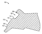
図1に示されるように、好ましい実施形態のシステムおよび方法は、ハンドルベース100、刃200、およびキャップ300を含んでいる。図1は本発明の実施形態の拡大された分解図である。図1に示されるように、ハンドルベース100は、それぞれあり継ぎ用の第1および第2の口側部104および106を有している受け入れ口102を含んでいる。また、ハンドルベースは、円形の口側部108と中央の固定用傾斜部110を含む。ハンドルベース100の受け入れ口102は、刃200のような刃を受け入れ、その後その刃がキャップ300で固定される。
As shown in FIG. 1, the system and method of the preferred embodiment includes a
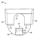
図2、3および4にハンドルベース100がより詳細に示される。図2および3は、図1に示すハンドルベースが拡大されたそれぞれ上面図および正面図である。図4は、図1に示されるハンドルベースの拡大された(図2での4-4線)横断面図である。
2, 3 and 4 show the
図2により詳細に示されるように、ハンドルベース100は、テーパ上のないしあり継ぎ用の口側部104および106と円形状の口側部108による3つの側部が境界をなす受け入れ口102を含んでいる。また、受け入れ口102の中には、中央の固定用傾斜部110が配置されている。図3では、ハンドルベースの前方の正面図に受け入れ口102のあり継ぎ用口側部104および106が詳細に示されている。図3に示されるように、それぞれの側部104および106は、以下でその詳細を説明するキャップ300のそれぞれ対応する、同様にテーパの側部とスライド可能に係合できるように設計されている。
As shown in more detail in FIG. 2, the
側部104および106のそれぞれは、受け入れ口102の面に対して斜めに延在する。側部は、テーパ状ないしあり継ぎ用開口を形成するのに十分は鋭角を含むどのような角度でも構成することができる。その角度は、キャップ300がハンドルベース100の受け入れ口102から直交する方向に簡単に移動しないように選ぶことができる。図3に示す例では、側部104および106は受け入れ口102の面からおよそ20度の角度で延在する。それぞれの側部104および106のテーパは、キャップ300をハンドルベース100に固定するために用いられるいくつかの技術の1つである。受け入れ口102からキャップ300が平行な方向に容易に移動するのを防止する第2の技術は、中央の固定用傾斜部110である。
Each of the
図4に、中央固定用傾斜部110がより詳細に示される。中央固定用傾斜部110は、一段高い平らな端116よりわずかに高さが低い丸みのある端112を含む。固定用傾斜部110の丸みのある端112における高さは、刃200(不図示)の厚さと等しいかわずかに低く、これによって、以下に詳細に示すように、刃が一度所定の位置に配置されると、キャップ300との係合がより容易になる。この高さが低くなることは、丸い端112と一段高い平らな端116の間の傾斜によっている。この傾斜114は、キャップ300上の第2の固定用傾斜部(図5の310)と係合するのに用いられる。傾斜114は、キャップの第2の固定用傾斜部310を、上述したテーパの側部による制限に抗して、また、一段高い平らな端116の上方で、受け入れ口102から直交する方向にわずかに移動させるのに助けとなる。第2の固定用傾斜部310が一段高い平らな端116を通り過ぎるとき、その固定用傾斜部は元の位置にスナップ篏合し、中央固定用傾斜部110の後ろの開口部120内に留まる。中央固定用傾斜部110の後部面118には上述したような傾斜が無く、それにより、第2の固定用傾斜部310が受け入れ口102に平行な方向で逆方向に移動することを防ぐことができる。
FIG. 4 shows the center fixing
キャップ300を固定する前に、ハンドルベース100の受け入れ口102は、角膜切開刃のような刃を受け入れ固定するように形状が定められている。刃200とハンドルベース100との間の係合は、実質的に刃200を受け入れ口102の上に位置させ刃を受け入れ口に向けて下方にスライドさせることによって起こり、それにより以下に詳細に述べるように要素の係合を行うことができる。
Prior to fixing the
図1に戻ると、刃200は、それぞれ肩の付いた第1および第2の側部と円形上の側部を有した曲線が付けられた端部202を含んでいる。中央の固定用傾斜部110がしっかりと固定して突き出るときに通る開口210(例えば、傾斜部110は開口210の内側周縁と摩擦係合できるような寸法になっている)が設けられている。刃200が入れ口102の中におかれる間、開口210と中央固定用傾斜部110とがかみ合うことによって、刃200は正確に位置決めされ、また、刃が捩れるのを防ぐことができる。
Returning to FIG. 1, the
刃200の正しい配置は、刃の片の付いた第1および第2の側部204および206と、受け入れ口102の第1および第2の口側部104および106との間のそれぞれの係合によっても確保される。刃の側部204および206それぞれの肩は、刃の開口210と中央固定用傾斜部110とがかみ合うとき受け入れ口102の外部をしっかりと押圧する。これによって、刃200が受け入れ口102の中で正しい位置で保持され、そして、キャップ300でベースに固定されることが確保される。刃200はまた、鋭利なすなわち機能する端部212を含み、この端部は、本発明の実施形態の範囲を限定しない、どんな方法ででも形成することができる。
The correct placement of the
ハンドルベース100に刃200を固定するために用いられるキャップ300は、図5および図6により詳細に示される。図5は、図1に示されるようなキャップの拡大された底面図であり、また、図6は、図1に示されるようなキャップの拡大された側方の正面図である。キャップ300とハンドルベース100との係合は、実質的に、適切に位置決めされた刃200の露出した面上にキャップを位置決めし、また、そのキャップを刃の面に対してしっかりとした状態でかつ刃の面の上部に延在する受け入れ口102の中にスライドさせることによって起きる。
The
図1のキャップ300は、それぞれ肩の付いた第1および第2の側部304および306を有する曲線の付いた端部302と、円形の側部308を含んでいる。キャップ300は、また、キャップが装着されている間に中央固定用傾斜部110と係合する第2の固定用傾斜部310を含む。第1および第2の側部は、キャップ装着の間、それぞれ第1および第2のあり継ぎ用の受け入れ口側部104および106とスライド可能に係合するテーパ部を含む。上述されたように、受け入れ口の側部104および106とキャップの側部304および306とのそれぞれの係合によって、キャップがハンドルベース100の受け入れ口102から直交する方向に移動することを防ぐことができる。
The
図5および図6により詳細に示されるように、キャップ300は、さらに肩318および320を含んでいる。この肩を越えて曲線状の端部302に向かいキャップの厚みが減少し、それによって、とりわけ、装着されている間および装着後の同一平面となるキャップの装着の間に第2の固定用傾斜部310が容易に変位することが可能となる。曲線状の端部302の反対側では、キャップの厚みが増加し、肩318および320のところが装着後に受け入れ口102の最大の深さを占めることができる。図5に示されるように、キャップの中央部分は、また、肩318および320から延在するレリーフ312を含んでいる。レリーフ312は、厚みが減少した曲線状の端部を肩318および320を越えてわずかな距離延在させたものであり、これによって、中央固定用傾斜部110を受け入れ、また、キャップ300が装着の後に受け入れ口102の中で平らなままでいることが可能となる。
As shown in more detail in FIGS. 5 and 6, the
図5および図6により詳細に示されるように、キャップ300は、受け入れ口102の円形の側部108と係合する円形の側部308を有している。キャップ300は、曲線状の端部302に隣接して、平坦面316に向かって高くなる傾斜314を含んだ第2の固定用傾斜部310を備えている。図4の傾斜114と同様に、傾斜314は中央固定用傾斜部110と係合するために用いられる。傾斜314と傾斜114と係合によって、第2の固定用傾斜部310は、テーパの側部304および306と同じ側部104および106とのそれぞれスライド可能な係合による制限に抗して上方にわずかに変位する。さらにわずかな係合動作によって、第2の固定用傾斜部310は中央固定用傾斜部110の一段高い平坦部116を通り過ぎて係合位置にスナップ篏合し、上述したように、中央固定用傾斜部110の後ろの開口120の中に留まる。キャップとハンドルベースのそれぞれあり継ぎ用側部304および306とあり継ぎ用側部104と106は、テーパ状とされ、これにより、2つの部分が係合するとき最初は隙間ばめとなる。キャップ300がその最終の位置の中にスライドして入るとき、間隙は減少してわずかなプレスばめとなる。このようなプレスばめ状態にあるあり継ぎテーパ部は、その作用によってキャップ300の主要な内側面を刃200に向かって引き下げる。これによって、組み立ての後がたつきがなく、また、傾斜部110および310がスナップ嵌合による互いの結合を維持することができる。
As shown in more detail in FIGS. 5 and 6, the
上述の実施形態が刃をハンドルに固定するのに用いられる手順は図7から図14に示される。図7から図14は、ハンドル100、刃200、およびキャップ300の装着を完成するための位置決めと動きを示している。図7および図8において、刃200は、先ずハンドルベース100の上に配置され、このとき刃の開口210を中央固定用傾斜部110と整列させる。図9および図10に示されるように、刃200は、その後しっかりとした状態で受け入れ口102の中まで位置を下げられ、これによって、中央固定用傾斜部110が刃の開口210を通って延在することが可能となる。そして、キャップ300は、露出した刃の面に平行に位置決めされ、また、受け入れ口102と係合できるように整列される。
The procedure used by the above-described embodiment to secure the blade to the handle is shown in FIGS. 7-14 illustrate the positioning and movement to complete the attachment of the
図11および図12に示されるように、キャップ300は、その後、露出した刃の面に対してぴったりとした状態で配置され、これによって刃の平行な面に沿ってスライドし受け入れ口102の中に入ることができる。これにより、受け入れ口側部104および106のあり継ぎ形状がそれぞれキャップ300の対応する側部304および306とスライドした係合が可能となる。キャップ300とベースハンドル100との間のスライド可能な係合が起こると、固定用傾斜部110および310は、上述したように、キャップが図13および14に示すような同一平面をなす位置に固定されるまで互いにかみ合い、これにより、刃200をベースハンドル100に固定することができる。
As shown in FIGS. 11 and 12, the
図4に戻ると、刃200の正しい位置決めは、受け入れ口102の平らな面をハンドルベースの中心線に対して望ましい角度で構成することに依っている。図4に示されるようにこの角度はおよそ45度であるが、上述の実施形態を変えずに、この角度を適用上要求されるのに応じて大きくしあるいは小さくすることができる。
Returning to FIG. 4, the correct positioning of the
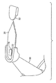
図15に示されるように、本発明の実施形態は、多くの手術用のナイフの安全ハンドルに用いることができ、ユーザーの操作性をより良くし、また、使用の間の刃の位置付けを容易にすることができる。図15において、ハンドルは、上述したようなハンドルベース100を備え、これによってハンドルの末端に刃200をしっかりと固定することができる。図15に示す例では、ハンドルベース100は、ハンドル末端における一体の延長として成型されるものであり、取り付け先端で概ね円形の断面を有し、この刃の取り付け先端における減少した断面積のところまでわずかに先細になっている。手術用ナイフの安全ハンドルの付加的な詳細は、さらに、Michael J. Morawski およびその他によって2004年4月21日に出願された米国特許出願10/828,501号、Michael J. Morawski およびその他によって2003年4月22日に出願された「手術用ナイフの安全ハンドル」という名称の米国特許出願10/420,614号、およびMichael J. Morawski およびその他によって2003年3月17日に出願された「手術用ナイフの安全ハンドル」という名称の米国意匠出願29/177,716号に説明されており、上記出願のそれぞれ内容はこの参照によって本明細書に含まれる。
As shown in FIG. 15, embodiments of the present invention can be used with many surgical knife safety handles to improve user operability and facilitate blade positioning during use. Can be. In FIG. 15, the handle comprises a
上述の実施形態のシステムおよび方法は、背着剤のような従来の刃取り付け方法より大きな利点を有している。エポキシのような接着剤の使用は、一般に面倒で大きな労力を要するもので、また、しばしば結合が予測できないものとなる。このような化合物は、また、一般に、炉またはUV光源を介した硬化周期を必要とする。これと対照的に、上述した本発明の実施形態によれば、硬化周期あるいは補助機器を必要とせずに、速くて、安全で、永久的な結合が可能となる。さらに、上記実施形態によれば、キャップと刃のスナップ動作を介して触覚による、また、聞き取ることのできるフィードバックがもたらされ、これにより、組み立てる者は、組み立て部品が所定の位置に適切に固定されたという反応を得ることができる。 The systems and methods of the embodiments described above have significant advantages over conventional blade attachment methods such as backpacks. The use of adhesives such as epoxies is generally cumbersome and labor intensive and often results in unpredictable bonds. Such compounds also generally require a curing cycle via a furnace or UV light source. In contrast, the above-described embodiments of the present invention allow for a fast, safe and permanent bond without the need for a curing cycle or auxiliary equipment. Furthermore, the above embodiment provides tactile and audible feedback via the cap and blade snapping action, which allows the assembler to properly secure the assembly in place. You can get a reaction that
本発明は、その代表的な実施形態について述べたが、当業者にとって、代表的な実施形態における多くの変更が、本質的に本発明の新規な教示および利点から外れないで容易に可能であることは明らかなことである。従って、総てのそのような変更は、特許請求の範囲およびそれと同等のもので規定される本発明の範囲に含まれるように意図したものである。 Although the present invention has been described with respect to exemplary embodiments thereof, many modifications in the exemplary embodiments can be readily made by those skilled in the art without departing from the novel teachings and advantages of the invention. That is clear. Accordingly, all such modifications are intended to be included within the scope of this invention as defined in the claims and their equivalents.
Claims (10)
平らな上面、底面、および第1、第2、第3および第4の側部を備えたキャップであって、前記第1、第2、第3および第4の側部の少なくとも1つが前記上面と底面との間に斜めに延在するキャップと、
底面および第1、第2および第3の側部を備えた受け入れ口を有する前記ハンドルベースであって、前記第1、第2および第3の側部の少なくとも1つが前記底面から斜めに延在し、前記受け入れ口がさらに第4の開かれた側部と開かれた上面を有して刃を受け入れることができ、前記受け入れ口が前記キャップとスライド可能に係合するハンドルベースと、
少なくとも1つの開口と曲線状の端部を有し前記受け入れ口内に取り付けられるようにされた刃であって、前記曲線状の端部が前記受け入れ口と前記キャップとの前記スライド可能な係合によって前記ハンドルベースに固定される刃と、
前記受け入れ口の面に配置された中央の固定用傾斜部と前記キャップの面に配置された第2の固定傾斜部であって、前記中央固定用傾斜部と前記第2固定傾斜部は前記受け入れ口と前記キャップとの前記スライド可能な係合によって互いに接触して固定するよう位置決めされた前記中央固定用傾斜部と前記第2固定傾斜部と、
を具えたことを特徴とする刃固定システム。In a blade fixing system for attaching a blade to a handle base in the handle of an ophthalmic or non-ophthalmic surgical knife,
A cap having a flat top surface, a bottom surface, and first, second, third and fourth sides, wherein at least one of the first, second, third and fourth sides is the top surface A cap extending diagonally between the bottom and the bottom;
The handle base having a bottom and a receiving port with first, second and third sides, wherein at least one of the first, second and third sides extends obliquely from the bottom. And the handle further has a fourth open side and an open top surface to receive the blade, the handle base slidably engaging the cap;
A blade having at least one opening and a curved end adapted to be mounted within the receiving port, wherein the curved end is slidably engaged by the receiving port and the cap; A blade fixed to the handle base;
A central fixing inclined portion disposed on the surface of the receiving port and a second fixed inclined portion disposed on the surface of the cap, wherein the central fixing inclined portion and the second fixed inclined portion are the receiving portions. The central fixed ramp and the second fixed ramp positioned to contact and fix each other by the slidable engagement of the mouth and the cap;
Blade fixing system characterized by comprising
Applications Claiming Priority (3)
| Application Number | Priority Date | Filing Date | Title |
|---|---|---|---|
| US10/835,286 | 2004-04-30 | ||
| US10/835,286 US7055248B2 (en) | 2004-04-30 | 2004-04-30 | Surgical knife blade attachment and method for using same |
| PCT/US2005/013498 WO2005110307A1 (en) | 2004-04-30 | 2005-04-20 | Surgical knife blade attachment and method for using same |
Publications (3)
| Publication Number | Publication Date |
|---|---|
| JP2007535363A JP2007535363A (en) | 2007-12-06 |
| JP2007535363A5 JP2007535363A5 (en) | 2008-06-05 |
| JP4789928B2 true JP4789928B2 (en) | 2011-10-12 |
Family
ID=34966315
Family Applications (1)
| Application Number | Title | Priority Date | Filing Date |
|---|---|---|---|
| JP2007510798A Expired - Fee Related JP4789928B2 (en) | 2004-04-30 | 2005-04-20 | Surgical knife blade mounting apparatus and method of using the apparatus |
Country Status (4)
| Country | Link |
|---|---|
| US (1) | US7055248B2 (en) |
| EP (1) | EP1742601A1 (en) |
| JP (1) | JP4789928B2 (en) |
| WO (1) | WO2005110307A1 (en) |
Families Citing this family (17)
| Publication number | Priority date | Publication date | Assignee | Title |
|---|---|---|---|---|
| US7022128B2 (en) | 2003-04-22 | 2006-04-04 | Becton, Dickinson And Company | Surgical knife safety handle |
| TW200509851A (en) * | 2003-04-22 | 2005-03-16 | Becton Dickinson Co | Surgical knife safety handle |
| TWI369970B (en) | 2004-10-20 | 2012-08-11 | Beaver Visitec Int Us Inc | Surgical knife safety handle having user operable lock |
| US7900363B1 (en) * | 2006-08-28 | 2011-03-08 | James Dale White | Exchange blade knife |
| US8978254B1 (en) * | 2006-08-28 | 2015-03-17 | James Dale White | Exchange blade knife |
| US8464430B2 (en) * | 2008-02-07 | 2013-06-18 | Beaver-Visitec International (Us), Inc. | Retractable safety knife |
| DE102009030874A1 (en) | 2009-06-29 | 2010-12-30 | Rheinische Fachhochschule Köln gGmbH | Scalpel, in particular for ophthalmological applications |
| US9055899B2 (en) * | 2009-10-22 | 2015-06-16 | Facet Technologies, Llc | Lancing device with improved guidance assembly |
| US8875405B2 (en) | 2010-04-09 | 2014-11-04 | Oasis Medical, Inc. | Micro surgical knife with safety feature |
| US9872799B2 (en) | 2012-04-24 | 2018-01-23 | The Regents Of The University Of Colorado, A Body Corporate | Intraocular device for dual incisions |
| US10682254B2 (en) | 2012-04-24 | 2020-06-16 | The Regents Of The University Of Colorado, A Body Corporate | Intraocular device for dual incisions |
| KR101538917B1 (en) * | 2014-06-05 | 2015-07-24 | 정재봉 | Blade handle for gingival incision for implant |
| US10779991B2 (en) | 2015-12-23 | 2020-09-22 | The Regents of the University of Colorado, a body corporated | Ophthalmic knife and methods of use |
| EP3510950B1 (en) * | 2016-10-13 | 2022-12-07 | Mani, Inc. | Nose knife |
| USD888517S1 (en) * | 2019-02-20 | 2020-06-30 | Macdon Industries Ltd. | Blade for a sickle |
| US11376751B2 (en) * | 2019-02-23 | 2022-07-05 | Martor Kg | Blade assembly and knife therefor |
| US20230293347A1 (en) | 2022-03-16 | 2023-09-21 | Sight Sciences, Inc. | Devices and methods for intraocular tissue manipulation |
Citations (3)
| Publication number | Priority date | Publication date | Assignee | Title |
|---|---|---|---|---|
| JPH0824265A (en) * | 1994-07-18 | 1996-01-30 | Michael L Haining | Knife for surgical operation |
| US20020065532A1 (en) * | 2000-11-29 | 2002-05-30 | Lewis Harrold | Keratome blade holder |
| JP2003504145A (en) * | 1999-07-15 | 2003-02-04 | オキュペイショナル・アンド・メディカル・イノベイションズ・プロプライエタリー・リミテッド | Surgical scalpel with retractable guard |
Family Cites Families (14)
| Publication number | Priority date | Publication date | Assignee | Title |
|---|---|---|---|---|
| US1754650A (en) * | 1926-10-26 | 1930-04-15 | Seaholm Nils | Surgeon's knife |
| US3383763A (en) * | 1966-06-29 | 1968-05-21 | Helge J. Strandfors | Razor with replaceable blade |
| US4660287A (en) | 1985-11-01 | 1987-04-28 | Decker John R | Knife with replaceable blade |
| US5203865A (en) | 1990-08-23 | 1993-04-20 | Siepser Steven B | Surgical knives for use in ophthalmic surgery |
| US5336235A (en) | 1991-07-23 | 1994-08-09 | Myers William D | Keratome |
| US5361902A (en) | 1992-06-05 | 1994-11-08 | Leonard Bloom | Surgical blade dispenser and disposal system for use during an operating procedure and method thereof |
| US5344424A (en) * | 1993-03-12 | 1994-09-06 | Roberts Philip L | Selectively retractable, disposable surgical knife |
| US5475925A (en) * | 1994-03-21 | 1995-12-19 | Newman; Philip H. | Three-piece retractable-bladed knife |
| US5433321A (en) | 1994-05-18 | 1995-07-18 | Bloom & Kreten | Article and method for safely mounting a blade on a surgical scalpel |
| US5924206A (en) | 1997-09-30 | 1999-07-20 | Becton, Dickinson And Company | Reusable device handle |
| US6112420A (en) * | 1999-08-10 | 2000-09-05 | S-B Power Tool Company | Blade clamp for reciprocating saw |
| US6626925B2 (en) * | 2001-03-29 | 2003-09-30 | Becton Dickinson And Company | Shielded surgical scalpel |
| CN1278809C (en) * | 2003-01-13 | 2006-10-11 | 苏州宝时得电动工具有限公司 | Quickly changeng and clamping mechanism of saw blade |
| US7022128B2 (en) | 2003-04-22 | 2006-04-04 | Becton, Dickinson And Company | Surgical knife safety handle |
-
2004
- 2004-04-30 US US10/835,286 patent/US7055248B2/en not_active Expired - Fee Related
-
2005
- 2005-04-20 JP JP2007510798A patent/JP4789928B2/en not_active Expired - Fee Related
- 2005-04-20 WO PCT/US2005/013498 patent/WO2005110307A1/en active Application Filing
- 2005-04-20 EP EP05737754A patent/EP1742601A1/en not_active Withdrawn
Patent Citations (3)
| Publication number | Priority date | Publication date | Assignee | Title |
|---|---|---|---|---|
| JPH0824265A (en) * | 1994-07-18 | 1996-01-30 | Michael L Haining | Knife for surgical operation |
| JP2003504145A (en) * | 1999-07-15 | 2003-02-04 | オキュペイショナル・アンド・メディカル・イノベイションズ・プロプライエタリー・リミテッド | Surgical scalpel with retractable guard |
| US20020065532A1 (en) * | 2000-11-29 | 2002-05-30 | Lewis Harrold | Keratome blade holder |
Also Published As
| Publication number | Publication date |
|---|---|
| JP2007535363A (en) | 2007-12-06 |
| WO2005110307A1 (en) | 2005-11-24 |
| US7055248B2 (en) | 2006-06-06 |
| EP1742601A1 (en) | 2007-01-17 |
| US20050245953A1 (en) | 2005-11-03 |
Similar Documents
| Publication | Publication Date | Title |
|---|---|---|
| JP4789928B2 (en) | Surgical knife blade mounting apparatus and method of using the apparatus | |
| US5924206A (en) | Reusable device handle | |
| US7022128B2 (en) | Surgical knife safety handle | |
| KR101119203B1 (en) | Surgical knife safety handle | |
| EP2087845B1 (en) | Retractable Safety Knife | |
| JP3660725B2 (en) | Surgical scalpel with protective member | |
| US10751103B2 (en) | Cutting/bending tool for polymer implant | |
| EP3600094B1 (en) | Entry cannula with intraocular-pressure activated seal | |
| WO2005009248A1 (en) | Pivotal and illuminated saphenous vein retractor with tapered design | |
| US9901367B2 (en) | Safety scalpel | |
| US20200060712A1 (en) | Device and method for improved surgical incisions | |
| EP1099432A2 (en) | A surgical swivel fixation ring device for use in eye surgery | |
| EP1437096A1 (en) | Wound clamp | |
| EP1477126B1 (en) | Shape and depth template for incisions with laser tips, particularly usable in bone surgery | |
| JP6122017B2 (en) | Intraocular lens surgery system | |
| US20170112522A1 (en) | Disposable swing scapel with reusable handle and blade configured for scalpel | |
| US20180242996A1 (en) | Disposable surgical swing scalpel with reusable scissor action handle | |
| KR101704614B1 (en) | Retractor for mandibular angle resection preventing vessel and nerve damage | |
| EP0622050B1 (en) | Microsurgical scalpel assembly | |
| JP2023525940A (en) | Apparatus and method for fixation of ocular tissue and provision of positioning points for surgical tools | |
| CN117597095A (en) | Trocar cannula assembly cap |
Legal Events
| Date | Code | Title | Description |
|---|---|---|---|
| A521 | Request for written amendment filed |
Free format text: JAPANESE INTERMEDIATE CODE: A523 Effective date: 20080417 |
|
| A621 | Written request for application examination |
Free format text: JAPANESE INTERMEDIATE CODE: A621 Effective date: 20080417 |
|
| A131 | Notification of reasons for refusal |
Free format text: JAPANESE INTERMEDIATE CODE: A131 Effective date: 20101019 |
|
| A977 | Report on retrieval |
Free format text: JAPANESE INTERMEDIATE CODE: A971007 Effective date: 20101021 |
|
| A711 | Notification of change in applicant |
Free format text: JAPANESE INTERMEDIATE CODE: A711 Effective date: 20101228 |
|
| A601 | Written request for extension of time |
Free format text: JAPANESE INTERMEDIATE CODE: A601 Effective date: 20110118 |
|
| A602 | Written permission of extension of time |
Free format text: JAPANESE INTERMEDIATE CODE: A602 Effective date: 20110128 |
|
| TRDD | Decision of grant or rejection written | ||
| A01 | Written decision to grant a patent or to grant a registration (utility model) |
Free format text: JAPANESE INTERMEDIATE CODE: A01 Effective date: 20110617 |
|
| A01 | Written decision to grant a patent or to grant a registration (utility model) |
Free format text: JAPANESE INTERMEDIATE CODE: A01 |
|
| A61 | First payment of annual fees (during grant procedure) |
Free format text: JAPANESE INTERMEDIATE CODE: A61 Effective date: 20110719 |
|
| FPAY | Renewal fee payment (event date is renewal date of database) |
Free format text: PAYMENT UNTIL: 20140729 Year of fee payment: 3 |
|
| R150 | Certificate of patent or registration of utility model |
Free format text: JAPANESE INTERMEDIATE CODE: R150 |
|
| R250 | Receipt of annual fees |
Free format text: JAPANESE INTERMEDIATE CODE: R250 |
|
| R250 | Receipt of annual fees |
Free format text: JAPANESE INTERMEDIATE CODE: R250 |
|
| R250 | Receipt of annual fees |
Free format text: JAPANESE INTERMEDIATE CODE: R250 |
|
| LAPS | Cancellation because of no payment of annual fees |