JP4787413B2 - Equipment for automatic hot melt supply and distribution - Google Patents
Equipment for automatic hot melt supply and distribution Download PDFInfo
- Publication number
- JP4787413B2 JP4787413B2 JP2000617019A JP2000617019A JP4787413B2 JP 4787413 B2 JP4787413 B2 JP 4787413B2 JP 2000617019 A JP2000617019 A JP 2000617019A JP 2000617019 A JP2000617019 A JP 2000617019A JP 4787413 B2 JP4787413 B2 JP 4787413B2
- Authority
- JP
- Japan
- Prior art keywords
- hot melt
- purge
- supply unit
- automatic
- stencil
- Prior art date
- Legal status (The legal status is an assumption and is not a legal conclusion. Google has not performed a legal analysis and makes no representation as to the accuracy of the status listed.)
- Expired - Fee Related
Links
Images


Classifications
-
- B—PERFORMING OPERATIONS; TRANSPORTING
- B41—PRINTING; LINING MACHINES; TYPEWRITERS; STAMPS
- B41F—PRINTING MACHINES OR PRESSES
- B41F35/00—Cleaning arrangements or devices
- B41F35/003—Cleaning arrangements or devices for screen printers or parts thereof
- B41F35/004—Cleaning arrangements or devices for screen printers or parts thereof for cylindrical screens
-
- B—PERFORMING OPERATIONS; TRANSPORTING
- B41—PRINTING; LINING MACHINES; TYPEWRITERS; STAMPS
- B41P—INDEXING SCHEME RELATING TO PRINTING, LINING MACHINES, TYPEWRITERS, AND TO STAMPS
- B41P2235/00—Cleaning
- B41P2235/10—Cleaning characterised by the methods or devices
- B41P2235/27—Suction devices
Landscapes
- Screen Printers (AREA)
- Inking, Control Or Cleaning Of Printing Machines (AREA)
- Coating Apparatus (AREA)
- Electric Connection Of Electric Components To Printed Circuits (AREA)
- Control And Other Processes For Unpacking Of Materials (AREA)
- External Artificial Organs (AREA)
- Medicines Containing Material From Animals Or Micro-Organisms (AREA)
- Application Of Or Painting With Fluid Materials (AREA)
- Manufacturing Of Printed Wiring (AREA)
Abstract
Description
【0001】
(発明の属する技術分野)
本発明は、ホットメルトを基材に自動供給し且つ分配するための装置に関する。
【0002】
(発明の背景)
スキージーエレメントに沿いステンシルの長さ全体に渡って延びるホットメルト分配パイプを含む装置が、知られている。分配パイプには、長手方向に相互に隣接して位置する多数の流出孔が備えられている。作動中に、ホットメルトが、分配パイプの一方の側に供給される。相互に隣接して位置する流出孔の断面は、ホットメルト供給側の下流方向において見ると、一定のステップサイズごとに(by a certain step size)大きくなっている。これは、ホットメルトの圧力が低下することに対する補償を行うこと、及び、実質的に均一なホットメルト分配を得ることを目的としている。
【0003】
この公知の装置の場合における欠点は、用いられるホットメルトの種類及びホットメルトの温度によって、流出孔において特定の分配及び特定のステップサイズを有する適切な分配パイプを使用しなければならないことである。特に、ホットメルトの温度は、大きく変わる可能性があり、その結果として、ホットメルトの粘度も変わる可能性がある。さらに、基材上における塗布幅によって、分配パイプの長さを適切に選択しなければならない。これは、ユーザーが、いくつかの異なる分配パイプをすぐに必要とすることを意味する。実際に、ホットメルトの分配には、要望されることが多く残っていることが分かっている。分配サイクルが完了した際、及び/または、別の種類のホットメルトに変更する際、及び/または、別の分配パイプに変更する際に、分配パイプのホットメルト内容物の全てが失われてしまう。具体的には、反応性ホットメルト、例えば、空気に触れて不可逆的に硬化するホットメルトが使用される場合には、望ましくないホットメルトの永続的硬化を防止するために特別な処置を取る必要がある。例えば、かなり長期にわたる停止中または分配パイプの保管中には、分配パイプを溶剤内に置かなければならないか、または、例えば、反応性ホットメルトの反応プロセスを止める熱可塑性ホットメルトのようなパージで分配パイプを満たさなければならない。これより、大量のホットメルトがまた失われることになる。
【0004】
請求項1の前提部分に係る装置が、独国特許発明第19736563号明細書から知られている。当該装置は、ステンシルを含み、その内部に、スキージーと、ホットメルトを分配するための中空の成形部材と、ホットメルトを加熱するための加熱部材を有する成形部材とが、配置されている。これらの成形部材は、スキージーの両側に配置され、スキージーの実質的に全長に渡って延び、よって、それらの間にスキージーを留める。中空の成形部材は、断面が長方形であり、底壁には多数の流出開口部が長手方向に相互に隣接して配置されて設けられている。
【0005】
この既知の装置の欠点は、所望の塗布幅、塗布されるホットメルトのタイプおよびホットメルトの温度により、適切なスキージーおよび成形部材の組立体を使用する必要があることである。実際に、このタイプの装置に、粘着性のある金属テープにより流出開口部を完全に気密に閉じることが提案されているが、これによって、組立体を長時間停止させ保管しておくことになる。したがって、中空の成形部材の中でのホットメルトの硬化を妨げることが、望ましい。テープを接着する前にステンシルから組立体全体を取り出す必要があるので、このテープ留めプロセスは時間の浪費である。組立体を取り出している間に、ホットメルトが望ましくない場所で流出開口部から滴り落ちる恐れがある。使用中に中空の成形部材中におけるホットメルトの圧力の降下を補償することはできず、その結果、ホットメルトの分配が不均一になってしまう。
【0006】
(発明の概要)
本発明の目的は、上述の欠点を克服する装置を提供すること、及び、具体的には、異なる塗布幅で及び/または異なる種類のホットメルトであっても、最適なホットメルト分配が、1つの同じ分配システムにより柔軟性のある方法で得られる装置を提供することである。
【0007】
この目的は、本発明による請求項1に記載の装置によって達成される。本装置は、ホットメルトを基材に塗布するための少なくとも1つのホットメルト塗布位置を有している。本装置は、ホットメルト印刷に用いるように、及び、ホットメルトコーティングに用いるように、設計することができる。塗布位置には、ステンシル及びスキージー装置と、スキージー装置に沿い移動可能な自動供給ユニットとが含まれる。自動供給ユニットは、ホットメルトを分配するノズルを含む。ノズルは、ホットメルト供給手段と流れが通じている。ホットメルト供給手段は、自動供給ユニットの動作に続くように設計されており、且つ、ホットメルトを正確な温度に維持する加熱手段を備えている。自動供給ユニットは、搬送手段によりスキージー装置に沿い前後に移動させることができ、また同時に、供給手段を適切に制御することにより、スキージー装置のスキージーエレメントの位置に所望の量のホットメルトを付与することができる。スキージーエレメントは、ステンシルを介して基材にホットメルトを押し付ける。可動な自動供給ユニットによって、ホットメルトは、スキージー装置の長さに渡って非常に正確に分配することができる。分配されるホットメルトの量及び自動供給ユニットが前後に移動する塗布幅は、簡易な方法で正確に調節可能である。これによって、本装置は、柔軟性を伴って且つ低コストで使用され、具体的には、種々の種類のホットメルト、異なるホットメルトの温度、及び、異なる塗布幅に容易に調節可能である。その上、自動供給及び分配は、部分的には、詰まるというリスクが最小限となる比較的大きな断面にノズルを設計可能であるということから、信頼性がある。分配サイクルの終わりにおいて及び/または別のプリント幅に変更する際に、ホットメルトは、殆どまたは全く失われずに済む。反応性ホットメルトが使用される場合に、費用及び時間のかかる処置を取る必要がないことは有利である。
【0008】
具体的には、本装置は、さらにパージ供給手段を備えており、自動供給ユニットには、さらに、パージ供給手段と流れが通じているパージディスペンスノズルが備えられている。これは、分配サイクルが完了した後、1つの同じ可動な自動供給ユニットを利用してスキージー装置の長さに渡り多量のパージを分配することができることを意味する。これは、反応性ホットメルトが使用された場合には特に重要である。パージは、ステンシル及びスキージー装置から反応性ホットメルトを一時に大量に流出させ、さらに、反応性ホットメルトの望ましくない反応の続行を防止する。
【0009】
さらに具体的には、上述のパージディスペンスノズルは、前記ノズルが、その自由端近くで、ホットメルトディスペンスノズル内において開口するように配置されている。ホットメルトが、ホットメルトディスペンスノズルの前部から噴出し、且つ、そこにおいて形成されるパージ媒体のシールプラグを生じるためには、パージを少量供給することで十分である。シールプラグは、ホットメルトが、反応し続けるのを防止し、その結果、例えば、空気に対してさらに不可逆的に硬化することがなくなる。実施形態のこの変更態様において、パージは、例えば、熱可塑性ホットメルトにより形成可能である。かなり多量のパージがスキージー装置に沿い計量供給された場合、自動的に、パージ媒質のシールプラグの形成が起こることが有利である。
【0010】
さらに、本発明の有利な実施形態は、請求項4から12において記載されている。
【0011】
本発明は、請求項13に記載の可動な自動供給ユニット、請求項14に記載のこのような自動供給ユニットとスキージー装置との組立体、及び請求項15記載の方法にも関連している。
【0012】
添付の図面に関連して本発明をさらに詳細に説明する。
【0013】
(好ましい実施の形態)
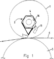
図1におけるホットメルト塗布位置は、スキージー装置2が内部に取り付けられ駆動可能なステンシル1を含む。スキージー装置2は、スキージーエレメント3とベアリング部4とを含む。ステンシル1は、別々に駆動可能な逆圧ローラー5(上部のみを図示)の上方に取り付けられている。基材6は、ステンシル1と逆圧ローラー5との間を搬送させることができる。スキージー装置2のベアリング部4は、中空に設計されている。前後に可動な自動供給ユニット10が、中空のベアリング部4内に備えられている。自動供給ユニット10には、ホットメルト分配用ノズル11が備えられている。本装置は、基材6にホットメルトを塗布することを目的とする。塗布サイクル中に、基材6は、ステンシル1に沿い搬送されるが、ステンシル1及び逆圧ローラー5は、別々に駆動される。それと同時に、自動供給ユニット10は、ベアリング部4の中を前後に移動する。この場合、自動供給ユニット10の移動方向は、基材6の搬送方向に垂直である。ノズル11によって、ホットメルトは、自動供給ユニット10が前後に移動する間に繰り返し塗布幅に渡り分配され、且つ、スキージーエレメント3の近くにおいて付与される。スキージーエレメント3は、ホットメルトを押して、ステンシル1を通す。自動供給ユニット10の移動速度と基材6の押出速度とを合わせることによって、全塗布サイクルの間に、スキージーエレメント3の全長に十分にホットメルトが存在することを確実になし得ることが有利である。
【0014】
図2から図4において、中空のベアリング部4には、長手方向のスリット15が備えられていることがはっきり見え、このスリット15を通じて、ノズル11が、外側に突出し且つ前後に移動することができる。
【0015】
自動供給ユニット10には、3つの摩擦減少ガイドエレメント16が備えられ、この摩擦減少ガイドエレメント16は、外周面に取り付けられ、例えば小ホイールによって形成される。さらに、スリット15の一方の長手方向端部に対して当接するガイドホイール17が、備えられている。これは、自動供給ユニット10が、殆ど力を掛けずに前後に移動可能であることを意味している。
【0016】
自動供給ユニット10は、供給ホース20(図2及び図3を参照)に接続されている。供給ホース20は、スキージー装置2の一方の端面においてガイドホイール21により支持されている。自動供給ユニット10がスキージー装置2に沿い前後に移動している間、ホース20は、それに伴って前後に移動する。
【0017】
供給ホース20には、ノズル11と流れが通じている単一の処理ラインを備えることができる。塗布サイクル中には、ホットメルトが、供給ホース20から供給され、またその一方で、塗布サイクルが終了した後には、供給ホース20内の同じ処理ラインからノズル11にパージを供給することができる。処理ライン及びノズル全体は、このようにパージが一時に大量に流されて清浄になる。さらに、非常に多くのパージを供給することができるので、ステンシル1及びスキージー装置2にも、ある程度流れてホットメルトがなくなる。
【0018】
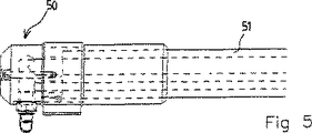
図5から図8は、自動供給ユニット50の好ましい実施形態を示し、この実施形態において、自動供給ユニット50に接続された供給ホース51は、ホットメルト供給ライン52と別個のパージ供給ライン53とを収容している。ホットメルト供給ライン52は、加熱エレメントにより囲まれており、この加熱エレメントは、ホットメルトが冷えるのを防止することに役立つ。ホットメルト供給ライン52は、自動供給ユニット50上のホットメルトディスペンスノズル55と流れが通じている。パージ供給ライン53は、パージディスペンスノズル56と流れが通じている。パージ供給ライン53は、同様に、加熱エレメントにより囲まれており、この加熱エレメントは、パージの温度を保つことを保証するのに役立たせることができる。このことは、特に、熱可塑性ホットメルトがパージとして使用される場合に、有利である。パージディスペンスノズル56は、その自由端の近くで、ホットメルトディスペンスノズル55内において開口するように配置されるのが有利である。塗布サイクルが終了してホットメルトの供給が中止され、パージの供給に切り換われば、この結果、ホットメルトディスペンスノズル55の最後の部分にあるホットメルトが、パージを送り込むことにより強制流出される。これにより、パージは、それと同時に自動的に、ホットメルト供給ライン52内にホットメルトがまだ存在する状況から遮断する。これは、反応性ホットメルトが使用される場合には特に有利である。よって、熱可塑性ホットメルトをパージとして使用することは、反応性ホットメルトが、自動供給ユニット50内またはホットメルト供給ライン52内において大気に対して永続的に硬化することを防止する簡易な方法である。ホットメルトディスペンスノズル55の最後部分内における熱可塑性ホットメルトは、良好なシールを形成し、永続的に硬化することはないので、供給ライン52からノズル55にホットメルトを再度供給することにより、次の塗布サイクルの初めにおいてノズル55の最後部分から容易に強制流出させることができる。
【0019】
変更態様において、ホットメルト供給ライン及びパージ供給ラインは、別個の供給ホース内に収容され、自動供給ユニットにそれぞれ接続している。
【0020】
別の変更態様において、自動供給ユニットには、別個のパージ供給ラインと流れが通じている別個のパージディスペンスノズルが備えられている。
【0021】
自動供給ユニットがスキージー装置の中空部分内に案内される、図1から図4において示された実施形態に加えて、変更態様では、スキージー装置の外側に備えられたガイド部上に自動供給ユニットを案内することもできる。スキージー装置に沿い塗布位置の少なくとも塗布幅に渡って延びる別個のガイド部を備えることも可能である。使用されるスキージーエレメントは、各場合において印刷中に形成されるホットメルトスレッド(hotmelt thread)を切り離し可能なことから、スキージーブレードであるのが有利である。
【0022】
前後に可動な自動供給ユニットは、いくつかの方法でスキージー装置に沿い前後に搬送可能である。図9から図11が、3つの変更態様を示している。
【0023】
図9a及び図9bにおいて、自動供給ユニット90が、堅い供給パイプ91に接続される。後者は、今度は、可撓性のある供給ホース92に接続される。供給ホース92は、ホットメルト供給部93またはパージ供給部94のいずれか所望する方と流れを通じさせるように配置可能である。駆動手段95が、自動供給ユニット90を前後に移動させるために備えられており、この駆動手段は、供給パイプ91の外周壁に作用する。駆動手段95は、ステンシル97の中を延びる、スキージー装置96の端面の一方に装着されている。駆動手段95を適切な方法で駆動させることにより、前記駆動手段は、前方または後方に供給パイプを押しやる。自動供給ユニット90は、供給パイプ91を伴ってスキージー装置に沿い前後に移動する。
【0024】
図10において示した変更態様は、大部分が図9のものに対応しており、相異するのは、駆動手段105が、この場合は、スキージー装置及びステンシルの外部に位置する固定ポイントにおいて装着されていることである。これは、本装置の停止時に、自動供給ユニット、供給パイプ、及び駆動手段を同時に取り外す必要なく、スキージー装置を取り外し可能であることを意味する。
【0025】
図11は、十分に可撓性のある供給ホース111を伴った変更態様を示し、この供給ホース111は、リール112に巻きつけ且つそれから再度繰り出すことが可能である。ホースは、可撓性があるが、繰り出し中に自動供給ユニットをその前方に押し込み可能な程度に堅い。
【0026】
示した実施形態に加えて、駆動手段が供給手段と相互作用する多くの変形が可能である。例えば、自動供給ユニットは、例えば別個の引っ張り及び/または押し込みエレメントのような別個の移動手段に接続することもできる。
【0027】
従って、基材上にホットメルトを自動供給且つ分配する多目的の装置が、本発明により得られる。前後に移動可能な自動供給ユニットは、計量供給され且つ分配されるホットメルトをいくつかの塗布幅及び異なる種類に、容易に調節可能である。パージディスペンスノズルは、ホットメルトディスペンスノズルの最後の部分において開口しているが、自動供給ユニットに備えられるのが非常に有利な場合がある。これにより、塗布サイクル以外におけるホットメルトの損失が最小限となり、且つ、ホットメルト特性が、かなり長い停止期間において否定的な意味で変化することが防止される。
【図面の簡単な説明】
【図1】本発明による好ましい実施形態の、塗布位置にある装置の概略断面図である。
【図2】図1の自動供給ユニットを伴ったスキージー装置の組立体の透視図である。
【図3】図2における供給手段を伴った自動供給ユニットの透視図である。
【図4】図2におけるスキージー装置の透視図である。
【図5】可動な自動供給ユニットの変更態様の平面図である。
【図6】図5の長手方向の断面図である。
【図7】図5の透視図である。
【図8】分解された部分を伴った図5の図である。
【図9a】第1の位置の自動供給ユニットを伴った塗布位置の、非常に概略化した図である。
【図9b】第2の位置の自動供給ユニットを伴った塗布位置の、非常に概略化した図である。
【図10a】図9による変更態様の図である。
【図10b】図9による変更態様の図である。
【図11a】図9によるさらなる変更態様の図である。
【図11b】図9によるさらなる変更態様の図である。[0001]
(Technical field to which the invention belongs)
The present invention relates to an apparatus for automatically supplying and distributing the e Ttomeruto the substrate.
[0002]
(Background of the Invention)
Devices are known that include hot melt distribution pipes that extend along the squeegee element over the length of the stencil . The distribution pipe is provided with a number of outflow holes located adjacent to each other in the longitudinal direction. During operation, hot melt is supplied to one side of the distribution pipe. When viewed in the downstream direction on the hot melt supply side, the cross-sections of the outflow holes located adjacent to each other are increased by a certain step size. This is intended to provide compensation for a decrease in hot melt pressure and to obtain a substantially uniform hot melt distribution.
[0003]
The disadvantage in the case of this known device is that depending on the type of hot melt used and the temperature of the hot melt, an appropriate distribution pipe having a specific distribution and a specific step size must be used in the outlet holes. In particular, the temperature of the hot melt can vary greatly, and as a result, the viscosity of the hot melt can also vary. Furthermore, the length of the distribution pipe must be appropriately selected according to the coating width on the substrate. This means that the user will soon need several different distribution pipes. In fact, it has been found that much demand remains for hot melt dispensing. When the dispensing cycle is complete and / or when changing to another type of hot melt and / or when changing to another dispensing pipe, all of the hot melt contents of the dispensing pipe are lost. . Specifically, when reactive hot melts are used, for example, hot melts that are irreversibly cured upon exposure to air, special measures must be taken to prevent permanent permanent cure of the undesirable hot melt. There is. For example, during fairly long outages or during distribution pipe storage, the distribution pipe must be placed in a solvent or purged, such as a thermoplastic hot melt that stops the reactive hot melt reaction process. The distribution pipe must be filled. From this, a large amount of hot melt will also be lost.
[0004]
A device according to the premise of claim 1 is known from DE 197375663. The apparatus includes a stencil, and a squeegee, a hollow molded member for distributing hot melt, and a molded member having a heating member for heating the hot melt are disposed therein. These molded members are located on either side of the squeegee and extend substantially the entire length of the squeegee, thus retaining the squeegee therebetween. The hollow molded member has a rectangular cross section, and a plurality of outflow openings are arranged on the bottom wall so as to be adjacent to each other in the longitudinal direction.
[0005]
The disadvantage of this known device is that depending on the desired application width, the type of hot melt applied and the temperature of the hot melt, it is necessary to use an appropriate squeegee and molded member assembly. In fact, it has been proposed for this type of device to close the outflow opening completely and tightly with adhesive metal tape, but this will keep the assembly stopped for a long time. . Therefore, it is desirable to prevent hot melt curing in the hollow molded member. This tape fastening process is time consuming because the entire assembly must be removed from the stencil before the tape is bonded. During removal of the assembly, hot melt can drip out of the outflow opening at an undesirable location. During use, the drop in hot melt pressure in the hollow molded member cannot be compensated for, resulting in non-uniform hot melt distribution.
[0006]
(Summary of Invention)
The object of the present invention is to provide an apparatus that overcomes the above-mentioned drawbacks, and in particular, the optimum hot melt distribution with different application widths and / or even different types of hot melts is 1 It is to provide a device that can be obtained in a flexible way with two identical dispensing systems.
[0007]
This object is achieved by the device according to claim 1 according to the present invention. The apparatus has at least one hot melt application position for applying hot melt to a substrate. The apparatus can be designed for use in hot melt printing and for use in hot melt coating. The application location includes a stencil and squeegee device and an automatic supply unit that is movable along the squeegee device. The automatic supply unit includes a nozzle for dispensing hot melt. The nozzle is in flow communication with the hot melt supply means. The hot melt supply means is designed to follow the operation of the automatic supply unit and includes heating means for maintaining the hot melt at an accurate temperature. The automatic supply unit can be moved back and forth along the squeegee device by the conveying means, and at the same time, by appropriately controlling the supply means, a desired amount of hot melt is applied to the position of the squeegee element of the squeegee device. be able to. The squeegee element presses the hot melt against the substrate through the stencil. With a movable automatic feeding unit, the hot melt can be dispensed very accurately over the length of the squeegee device. The amount of hot melt dispensed and the coating width over which the automatic supply unit moves back and forth can be accurately adjusted in a simple manner. This allows the apparatus to be used with flexibility and at low cost, and in particular, can be easily adjusted to different types of hot melts, different hot melt temperatures and different application widths. Moreover, automatic feeding and dispensing is reliable because, in part, the nozzle can be designed with a relatively large cross-section that minimizes the risk of clogging. Little or no hot melt is lost at the end of the dispensing cycle and / or when changing to another print width. Advantageously, when reactive hot melts are used, there is no need to take expensive and time consuming procedures.
[0008]
Specifically, the apparatus further includes a purge supply unit, and the automatic supply unit further includes a purge dispense nozzle that communicates with the purge supply unit. This means that a large amount of purge can be dispensed over the length of the squeegee device using one and the same movable autofeed unit after the dispensing cycle is complete. This is particularly important when a reactive hot melt is used. The purge causes the reactive hot melt to flow out of the stencil and squeegee apparatus in large quantities at one time, and further prevents the reactive hot melt from continuing undesirable reactions.
[0009]
More specifically, the purge dispense nozzle described above is arranged such that the nozzle opens near the free end in the hot melt dispense nozzle. It is sufficient to supply a small amount of purge in order for the hot melt to spout from the front of the hot melt dispensing nozzle and produce a seal plug of purge medium formed therein. The seal plug prevents the hot melt from continuing to react so that it does not cure further irreversibly, for example to air. In this variation of the embodiment, the purge can be formed by, for example, a thermoplastic hot melt. Advantageously, when a significant amount of purge is metered along the squeegee device, the formation of a seal plug of the purge medium occurs automatically.
[0010]
Further advantageous embodiments of the invention are described in claims 4 to 12.
[0011]
The invention also relates to a movable automatic feeding unit according to claim 13, an assembly of such an automatic feeding unit and a squeegee device according to claim 14, and a method according to
[0012]
The invention will now be described in more detail with reference to the accompanying drawings.
[0013]
(Preferred embodiment)
The hot melt application position in FIG. 1 includes a stencil 1 to which a
[0014]
2 to 4, it can be clearly seen that the hollow bearing portion 4 is provided with a
[0015]
The automatic supply unit 10 is provided with three friction
[0016]
The automatic supply unit 10 is connected to a supply hose 20 (see FIGS. 2 and 3). The
[0017]
The
[0018]
5 to 8 show a preferred embodiment of the
[0019]
In a variant, the hot melt supply line and the purge supply line are housed in separate supply hoses and are each connected to an automatic supply unit.
[0020]
In another variation, the automatic supply unit is provided with a separate purge dispense nozzle in flow communication with a separate purge supply line.
[0021]
In addition to the embodiment shown in FIGS. 1 to 4 in which the automatic supply unit is guided in the hollow part of the squeegee device, in a modified embodiment, the automatic supply unit is placed on a guide part provided outside the squeegee device. You can also guide. It is also possible to provide a separate guide part extending along the squeegee device over at least the application width of the application position. The squeegee element used is advantageously a squeegee blade, since in each case the hotmelt thread formed during printing can be separated.
[0022]
The automatic feeding unit movable back and forth can be transported back and forth along the squeegee device in several ways. 9 to 11 show three modification modes.
[0023]
In FIGS. 9 a and 9 b, the
[0024]
The modification shown in FIG. 10 largely corresponds to that of FIG. 9, except that the drive means 105 is in this case mounted at a fixed point located outside the squeegee device and the stencil. It has been done. This means that when the device is stopped, the squeegee device can be removed without having to remove the automatic supply unit, the supply pipe and the drive means at the same time.
[0025]
FIG. 11 shows a variation with a sufficiently flexible supply hose 111 that can be wound around a
[0026]
In addition to the embodiment shown, many variations are possible in which the drive means interacts with the supply means. For example, the automatic feeding unit can also be connected to a separate moving means such as, for example, a separate pull and / or push element.
[0027]
Thus, a multipurpose device for automatically feeding and dispensing hot melt on a substrate is obtained according to the present invention. The automatic feed unit which can be moved back and forth can easily adjust the hot melt dispensed and dispensed to several application widths and different types. The purge dispense nozzle is open at the last part of the hot melt dispense nozzle, but it may be very advantageous to be provided in an automatic supply unit. This minimizes hot melt loss outside of the application cycle and prevents hot melt properties from changing in a negative sense during a fairly long outage period.
[Brief description of the drawings]
FIG. 1 is a schematic cross-sectional view of a device in a coating position of a preferred embodiment according to the present invention.
2 is a perspective view of an assembly of a squeegee device with the automatic supply unit of FIG.
3 is a perspective view of an automatic supply unit with supply means in FIG. 2. FIG.
4 is a perspective view of the squeegee device in FIG. 2. FIG.
FIG. 5 is a plan view of a change mode of the movable automatic supply unit.
6 is a longitudinal sectional view of FIG. 5. FIG.
FIG. 7 is a perspective view of FIG.
8 is a diagram of FIG. 5 with the parts disassembled.
FIG. 9a is a very schematic view of the application position with the automatic supply unit in the first position.
FIG. 9b is a very schematic view of the application position with the automatic supply unit in the second position.
10a is a diagram of a modification according to FIG.
10b is a diagram of the modification according to FIG.
11a is a diagram of a further modification according to FIG.
11b is a diagram of a further modification according to FIG.
Claims (15)
該装置は、基材押出手段と、ホットメルト供給手段と、ホットメルトを基材に塗布するための少なくとも1つのホットメルト塗布位置とを有し、
前記ホットメルト塗布位置において、ステンシルと、ホットメルト分配手段と、前記ステンシルの中を延び前記ステンシルを介して基材にホットメルトを押し付けるスキージー装置とを含み、
該装置は、自動供給ユニットと、前記スキージー装置に沿い前後に前記自動供給ユニットを移動させる駆動手段とをさらに備え、
前記ホットメルト分配手段は、ホットメルト分配用ノズルを含み、前記ホットメルト分配用ノズルは、可動な前記自動供給ユニットに取り付けられていることを特徴とする装置。An apparatus for automatically feeding and dispensing hot melt on a substrate,
The apparatus has a substrate extrusion means, a hot melt supply means, and at least one hot melt application position for applying the hot melt to the substrate,
A stencil, hot melt dispensing means, and a squeegee device that extends through the stencil and presses the hot melt against the substrate through the stencil at the hot melt application position;
The apparatus further comprises an automatic supply unit and drive means for moving the automatic supply unit back and forth along the squeegee device,
The hot-melt dispensing means includes a hot-melt dispensing nozzle, and the hot-melt dispensing nozzle is attached to the movable automatic supply unit.
前記パージ分配手段は、可動な前記自動供給ユニットに取り付けられたパージ分配用ノズルを含む請求項1に記載の装置。Purge supply means for supplying a purge for allowing hot melt to flow out of the stencil and squeegee device, and purge distribution means in flow communication with the purge supply means;
The apparatus according to claim 1, wherein the purge distribution means includes a purge distribution nozzle attached to the movable automatic supply unit.
ホットメルト分配用ノズルが取り付けられているとともにホットメルト供給手段が接続されており、前記ホットメルト分配用ノズルおよび前記ホットメルト供給手段の間のホットメルトの流れを通じさせている自動供給ユニット。A movable automatic feeding unit for a device according to any of claims 1-12 ,
An automatic supply unit to which a hot melt distribution nozzle is attached and a hot melt supply means is connected, and a hot melt flow is allowed to flow between the hot melt distribution nozzle and the hot melt supply means.
前記スキージー装置に沿い前後に前記自動供給ユニットを移動させる駆動手段を備え、
前記自動供給ユニットは、ホットメルト分配用ノズルが取り付けられているとともにホットメルト供給手段が接続されており、前記ホットメルト分配用ノズルおよび前記ホットメルト供給手段の間のホットメルトの流れを通じさせている組立体。A movable automatic feeding unit and squeegee device assembly for a device according to any of the preceding claims , comprising:
Drive means for moving the automatic supply unit back and forth along the squeegee device;
The automatic supply unit is attached with a hot melt dispensing nozzle and connected with a hot melt supply means, and allows the hot melt flow between the hot melt distribution nozzle and the hot melt supply means to flow. Assembly.
前記自動供給ユニット及び前記ホットメルト供給手段の前記駆動手段を制御することにより、ホットメルトを自動供給し且つ分配するステップと、
前記ステンシル上のホットメルトを押し出すステップと、
前記自動供給ユニット及び前記パージ供給手段の前記駆動手段を制御することによってパージを自動供給し且つ分配するステップとを含む方法。A method for applying a hot melt to a substrate by the apparatus according to any one of claims 2 to 12,
Automatically supplying and dispensing hot melt by controlling the drive means of the automatic supply unit and the hot melt supply means;
Extruding a hot melt on the stencil;
Automatically supplying and distributing a purge by controlling the drive means of the automatic supply unit and the purge supply means.
Applications Claiming Priority (3)
| Application Number | Priority Date | Filing Date | Title |
|---|---|---|---|
| NL1011993A NL1011993C2 (en) | 1999-05-07 | 1999-05-07 | Screen printing device with a cleaning unit that can be moved in a template. |
| NL1011993 | 1999-05-07 | ||
| PCT/NL2000/000292 WO2000068011A1 (en) | 1999-05-07 | 2000-05-08 | Device for the dosing and distribution of hotmelt |
Publications (3)
| Publication Number | Publication Date |
|---|---|
| JP2002544009A JP2002544009A (en) | 2002-12-24 |
| JP2002544009A5 JP2002544009A5 (en) | 2007-06-28 |
| JP4787413B2 true JP4787413B2 (en) | 2011-10-05 |
Family
ID=19769149
Family Applications (1)
| Application Number | Title | Priority Date | Filing Date |
|---|---|---|---|
| JP2000617019A Expired - Fee Related JP4787413B2 (en) | 1999-05-07 | 2000-05-08 | Equipment for automatic hot melt supply and distribution |
Country Status (9)
| Country | Link |
|---|---|
| US (2) | US6619207B1 (en) |
| EP (2) | EP1052096B1 (en) |
| JP (1) | JP4787413B2 (en) |
| AT (2) | ATE278552T1 (en) |
| AU (1) | AU4625500A (en) |
| DE (2) | DE60014488T2 (en) |
| ES (2) | ES2225013T3 (en) |
| NL (1) | NL1011993C2 (en) |
| WO (1) | WO2000068011A1 (en) |
Families Citing this family (10)
| Publication number | Priority date | Publication date | Assignee | Title |
|---|---|---|---|---|
| US20020144610A1 (en) * | 2000-06-20 | 2002-10-10 | Peter Zimmer | Device and process for the removal of the screen coating from printing screens for silk screen printing |
| US7134389B2 (en) * | 2002-02-22 | 2006-11-14 | Minami Co., Ltd. | Screen printing apparatus |
| US20040238003A1 (en) * | 2003-05-30 | 2004-12-02 | Gerald Pham-Van-Diep | Stencil cleaner for use in the solder paste print operation |
| US9153341B2 (en) * | 2005-10-18 | 2015-10-06 | Semiconductor Energy Laboratory Co., Ltd. | Shift register, semiconductor device, display device, and electronic device |
| KR100953495B1 (en) * | 2008-05-21 | 2010-04-16 | 건국대학교 산학협력단 | Method and Apparatus for Roll-To-Roll type Printing |
| US8247827B2 (en) * | 2008-09-30 | 2012-08-21 | Bridgelux, Inc. | LED phosphor deposition |
| ES2909467T3 (en) | 2013-12-31 | 2022-05-06 | Johnson & Johnson Consumer Inc | Process for forming a shaped film product |
| WO2015103030A1 (en) | 2013-12-31 | 2015-07-09 | Johnson & Johnson Consumer Companies, Inc. | Process for forming a multi layered shaped film |
| JP6517216B2 (en) | 2013-12-31 | 2019-05-22 | ジョンソン・アンド・ジョンソン・コンシューマー・インコーポレイテッド | Single pass method for forming multilayer shaped film products |
| KR101779411B1 (en) | 2017-08-31 | 2017-09-18 | 인치영 | Screen printing system of printed circuit system |
Citations (4)
| Publication number | Priority date | Publication date | Assignee | Title |
|---|---|---|---|---|
| JPS57110361A (en) * | 1980-09-16 | 1982-07-09 | Mitter Mathias | Device for supplying applying medium to face-shaped material |
| JPS62132780U (en) * | 1986-02-13 | 1987-08-21 | ||
| JPH08281170A (en) * | 1995-04-12 | 1996-10-29 | Nordson Corp | Rotary coater and heater hood assembly |
| DE19736563C1 (en) * | 1997-08-22 | 1998-10-22 | Trans Textil Gmbh | Apparatus for applying molten adhesive to tracks |
Family Cites Families (11)
| Publication number | Priority date | Publication date | Assignee | Title |
|---|---|---|---|---|
| AT335961B (en) * | 1973-12-28 | 1977-04-12 | Zimmer Peter | DEVICE FOR CLEANING A SCREEN PRINTING ROTATION STENCIL |
| US4622239A (en) * | 1986-02-18 | 1986-11-11 | At&T Technologies, Inc. | Method and apparatus for dispensing viscous materials |
| AT393246B (en) * | 1989-03-31 | 1991-09-10 | Hwb Maschinenbau | APPLICATION DEVICE FOR APPLYING FLOWABLE MEDIA ON LEVEL SURFACES, RAILS, ROLLERS OD. DGL. |
| BR9505844A (en) * | 1994-02-12 | 1996-02-13 | Johannes Zimmer | Self-cleaning device for applying a substance on a textile section |
| US5483884A (en) * | 1994-10-31 | 1996-01-16 | At&T Corp. | Method and apparatus for setting up a stencil printer |
| US5584932A (en) * | 1995-04-12 | 1996-12-17 | Nordson Corporation | Electrical control circuit for controlling the speed and position of a rotary screen coater with respect to the line speed and position of a moving web |
| DE29517099U1 (en) * | 1995-10-17 | 1997-02-27 | Zimmer, Johannes, Klagenfurt | Application device |
| NL1005308C2 (en) * | 1997-02-18 | 1998-08-20 | Stork Brabant Bv | Squeegee with a fixed load-bearing part. |
| JPH10250044A (en) * | 1997-03-18 | 1998-09-22 | Ichinose Internatl:Kk | Rotary screen textile printer |
| DE19806040A1 (en) * | 1998-02-13 | 1999-09-09 | Stork Mbk Gmbh | Device and method for applying a medium to a substrate and system with several such devices |
| US6145434A (en) * | 1998-03-20 | 2000-11-14 | Ricoh Company, Ltd. | Stencil printing method and device |
-
1999
- 1999-05-07 NL NL1011993A patent/NL1011993C2/en not_active IP Right Cessation
-
2000
- 2000-05-02 ES ES00201589T patent/ES2225013T3/en not_active Expired - Lifetime
- 2000-05-02 EP EP00201589A patent/EP1052096B1/en not_active Expired - Lifetime
- 2000-05-02 DE DE60014488T patent/DE60014488T2/en not_active Expired - Lifetime
- 2000-05-02 AT AT00201589T patent/ATE278552T1/en active
- 2000-05-05 US US09/566,280 patent/US6619207B1/en not_active Expired - Fee Related
- 2000-05-08 AU AU46255/00A patent/AU4625500A/en not_active Abandoned
- 2000-05-08 EP EP00927953A patent/EP1177099B1/en not_active Expired - Lifetime
- 2000-05-08 AT AT00927953T patent/ATE247561T1/en not_active IP Right Cessation
- 2000-05-08 WO PCT/NL2000/000292 patent/WO2000068011A1/en active IP Right Grant
- 2000-05-08 DE DE60004659T patent/DE60004659T2/en not_active Expired - Lifetime
- 2000-05-08 JP JP2000617019A patent/JP4787413B2/en not_active Expired - Fee Related
- 2000-05-08 ES ES00927953T patent/ES2204591T3/en not_active Expired - Lifetime
-
2001
- 2001-10-29 US US10/021,418 patent/US6656274B2/en not_active Expired - Fee Related
Patent Citations (4)
| Publication number | Priority date | Publication date | Assignee | Title |
|---|---|---|---|---|
| JPS57110361A (en) * | 1980-09-16 | 1982-07-09 | Mitter Mathias | Device for supplying applying medium to face-shaped material |
| JPS62132780U (en) * | 1986-02-13 | 1987-08-21 | ||
| JPH08281170A (en) * | 1995-04-12 | 1996-10-29 | Nordson Corp | Rotary coater and heater hood assembly |
| DE19736563C1 (en) * | 1997-08-22 | 1998-10-22 | Trans Textil Gmbh | Apparatus for applying molten adhesive to tracks |
Also Published As
| Publication number | Publication date |
|---|---|
| US20020076496A1 (en) | 2002-06-20 |
| ES2225013T3 (en) | 2005-03-16 |
| DE60014488D1 (en) | 2004-11-11 |
| WO2000068011A1 (en) | 2000-11-16 |
| DE60014488T2 (en) | 2005-05-19 |
| AU4625500A (en) | 2000-11-21 |
| DE60004659D1 (en) | 2003-09-25 |
| JP2002544009A (en) | 2002-12-24 |
| EP1052096A1 (en) | 2000-11-15 |
| EP1177099B1 (en) | 2003-08-20 |
| EP1052096B1 (en) | 2004-10-06 |
| US6619207B1 (en) | 2003-09-16 |
| US6656274B2 (en) | 2003-12-02 |
| ATE278552T1 (en) | 2004-10-15 |
| ATE247561T1 (en) | 2003-09-15 |
| EP1177099A1 (en) | 2002-02-06 |
| NL1011993C2 (en) | 2000-11-09 |
| ES2204591T3 (en) | 2004-05-01 |
| DE60004659T2 (en) | 2004-06-17 |
Similar Documents
| Publication | Publication Date | Title |
|---|---|---|
| JP4787413B2 (en) | Equipment for automatic hot melt supply and distribution | |
| KR20140099883A (en) | Melting system | |
| US5099758A (en) | Apparatus for applying a flowable medium to a surface, especially a web, roll or the like | |
| JPH05201170A (en) | Main structure | |
| JP2002544009A5 (en) | ||
| US8079324B2 (en) | Device for later application of a two-component material on a substrate | |
| WO2010116442A1 (en) | Coating die and coating apparatus comprising the same | |
| US9797035B2 (en) | Apparatus for applying a hot-melt adhesive to a substrate | |
| JP7259294B2 (en) | Adhesive coating device and inkjet image forming device | |
| JPH062249B2 (en) | Space plate manufacturing equipment | |
| CN108136799A (en) | Band coating unit and printing equipment | |
| KR20010072637A (en) | Device for applying a decoration to a crate | |
| FI81733C (en) | Coating device for material webs | |
| EP2629983B1 (en) | Adhesive delivering head for binding machines and machine incorporating the head | |
| JP2004337150A (en) | Method for applying paste on moving belt material and device for performing the method | |
| TW201615286A (en) | Automatic glue dispensing device | |
| KR100757044B1 (en) | bond to spray a device of film for decoration | |
| EP1894636A2 (en) | Glue dispensing apparatus | |
| US20230294323A1 (en) | Device and method for producing an adhesive thread and for connecting workpieces using the adhesive thread | |
| KR19990070826A (en) | Label winding device | |
| US6613149B1 (en) | Banderole gluing apparatus and method | |
| JPH09193356A (en) | Ink fountain having ink fountain roller in ink arrangement for printing machine | |
| JPS59173163A (en) | Method and device for coating viscous material | |
| JPS62262770A (en) | Apparatus for producing spacer sheet | |
| EP2722108B1 (en) | Dosing device and method for its cleaning |
Legal Events
| Date | Code | Title | Description |
|---|---|---|---|
| A521 | Request for written amendment filed |
Free format text: JAPANESE INTERMEDIATE CODE: A523 Effective date: 20070508 |
|
| A621 | Written request for application examination |
Free format text: JAPANESE INTERMEDIATE CODE: A621 Effective date: 20070508 |
|
| A131 | Notification of reasons for refusal |
Free format text: JAPANESE INTERMEDIATE CODE: A131 Effective date: 20100512 |
|
| A601 | Written request for extension of time |
Free format text: JAPANESE INTERMEDIATE CODE: A601 Effective date: 20100809 |
|
| A602 | Written permission of extension of time |
Free format text: JAPANESE INTERMEDIATE CODE: A602 Effective date: 20100816 |
|
| A521 | Request for written amendment filed |
Free format text: JAPANESE INTERMEDIATE CODE: A523 Effective date: 20101112 |
|
| A131 | Notification of reasons for refusal |
Free format text: JAPANESE INTERMEDIATE CODE: A131 Effective date: 20110201 |
|
| A521 | Request for written amendment filed |
Free format text: JAPANESE INTERMEDIATE CODE: A523 Effective date: 20110412 |
|
| TRDD | Decision of grant or rejection written | ||
| A01 | Written decision to grant a patent or to grant a registration (utility model) |
Free format text: JAPANESE INTERMEDIATE CODE: A01 Effective date: 20110621 |
|
| A01 | Written decision to grant a patent or to grant a registration (utility model) |
Free format text: JAPANESE INTERMEDIATE CODE: A01 |
|
| A61 | First payment of annual fees (during grant procedure) |
Free format text: JAPANESE INTERMEDIATE CODE: A61 Effective date: 20110715 |
|
| R150 | Certificate of patent or registration of utility model |
Free format text: JAPANESE INTERMEDIATE CODE: R150 Ref document number: 4787413 Country of ref document: JP Free format text: JAPANESE INTERMEDIATE CODE: R150 |
|
| FPAY | Renewal fee payment (event date is renewal date of database) |
Free format text: PAYMENT UNTIL: 20140722 Year of fee payment: 3 |
|
| R250 | Receipt of annual fees |
Free format text: JAPANESE INTERMEDIATE CODE: R250 |
|
| R250 | Receipt of annual fees |
Free format text: JAPANESE INTERMEDIATE CODE: R250 |
|
| R250 | Receipt of annual fees |
Free format text: JAPANESE INTERMEDIATE CODE: R250 |
|
| R250 | Receipt of annual fees |
Free format text: JAPANESE INTERMEDIATE CODE: R250 |
|
| R250 | Receipt of annual fees |
Free format text: JAPANESE INTERMEDIATE CODE: R250 |
|
| LAPS | Cancellation because of no payment of annual fees |