JP4787173B2 - Color-shifting retroreflector and method for manufacturing the same - Google Patents
Color-shifting retroreflector and method for manufacturing the same Download PDFInfo
- Publication number
- JP4787173B2 JP4787173B2 JP2006547445A JP2006547445A JP4787173B2 JP 4787173 B2 JP4787173 B2 JP 4787173B2 JP 2006547445 A JP2006547445 A JP 2006547445A JP 2006547445 A JP2006547445 A JP 2006547445A JP 4787173 B2 JP4787173 B2 JP 4787173B2
- Authority
- JP
- Japan
- Prior art keywords
- layer
- reflective
- color
- microspheres
- article
- Prior art date
- Legal status (The legal status is an assumption and is not a legal conclusion. Google has not performed a legal analysis and makes no representation as to the accuracy of the status listed.)
- Expired - Fee Related
Links
Images


Classifications
-
- G—PHYSICS
- G02—OPTICS
- G02B—OPTICAL ELEMENTS, SYSTEMS OR APPARATUS
- G02B5/00—Optical elements other than lenses
- G02B5/12—Reflex reflectors
- G02B5/126—Reflex reflectors including curved refracting surface
- G02B5/128—Reflex reflectors including curved refracting surface transparent spheres being embedded in matrix
-
- Y—GENERAL TAGGING OF NEW TECHNOLOGICAL DEVELOPMENTS; GENERAL TAGGING OF CROSS-SECTIONAL TECHNOLOGIES SPANNING OVER SEVERAL SECTIONS OF THE IPC; TECHNICAL SUBJECTS COVERED BY FORMER USPC CROSS-REFERENCE ART COLLECTIONS [XRACs] AND DIGESTS
- Y10—TECHNICAL SUBJECTS COVERED BY FORMER USPC
- Y10T—TECHNICAL SUBJECTS COVERED BY FORMER US CLASSIFICATION
- Y10T428/00—Stock material or miscellaneous articles
- Y10T428/24—Structurally defined web or sheet [e.g., overall dimension, etc.]
- Y10T428/24479—Structurally defined web or sheet [e.g., overall dimension, etc.] including variation in thickness
- Y10T428/2457—Parallel ribs and/or grooves
- Y10T428/24579—Parallel ribs and/or grooves with particulate matter
Description
再帰反射物品は、入射光の方向を光源に向かって斜方向に変更する能力を有する。このユニークな能力によって、様々な基材上での再帰反射物品の幅広い用途がもたらされる。例えば再帰反射物品は、道路標識およびバリケードのような平らで曲げられない基材において;波形金属トラックトレーラー、ナンバープレートおよび交通障壁のような不規則表面において;そして道路工事作業員安全ベスト、ジョギングシューズ、ロールアップ標識およびキャンバス サイデッド トラック(canvas−sided trucks)のような屈曲性基材において使用可能である。 The retroreflective article has the ability to change the direction of incident light obliquely toward the light source. This unique capability provides a wide range of uses for retroreflective articles on various substrates. For example, retroreflective articles can be used on flat, non-bent substrates such as road signs and barricades; on irregular surfaces such as corrugated metal truck trailers, license plates and traffic barriers; and road construction worker safety vests, jogging shoes It can be used on flexible substrates such as roll-up signs and canvas-sided tracks.
再帰反射物品の一種としてはビーズが挙げられる。かかるビーズ物品は、一般的に入射光を再帰反射するように複数のガラスまたはセラミックのミクロスフィアを使用する。典型的にミクロスフィアは支持フィルム中に部分的に包埋され、そして鏡面反射材料はミクロスフィアの層と支持フィルムとの間に提供される。反射材料は金属層(例えば、米国特許第3,700,478号明細書(ビンガム(Bingham)‘478)および米国特許第4,648,932号明細書(ベイリー(Bailey))に開示されるアルミニウムコーティング)、異なる屈折率を有する複数の無機材料層から製造された無機誘電ミラー(例えば、米国特許第3,700,305号明細書(ビンガム(Bingham)‘305)および米国特許第4,763,985号明細書(ビンガム(Bingham)‘985)に開示される通り)または異なる屈折率を有する複数のポリマー層から製造された有機反射コーティング(例えば、米国特許第6,172,810B1号明細書(フレミング(Fleming)ら‘810)に開示される通り)であり得る。 One type of retroreflective article is a bead. Such bead articles typically use a plurality of glass or ceramic microspheres to retroreflect incident light. Typically, the microspheres are partially embedded in a support film and a specular reflective material is provided between the microsphere layer and the support film. The reflective material may be a metal layer (eg, aluminum disclosed in US Pat. No. 3,700,478 (Bingham '478) and US Pat. No. 4,648,932 (Bailey)). Coating), inorganic dielectric mirrors made from a plurality of layers of inorganic material having different refractive indices (eg, US Pat. No. 3,700,305 (Bingham '305) and US Pat. No. 4,763) No. 985 (as disclosed in Bingham '985) or organic reflective coatings made from multiple polymer layers having different refractive indices (eg, US Pat. No. 6,172,810 B1) As disclosed in Fleming et al. '810).
ビーズ再帰反射物品の種類としては、露出レンズ、包埋レンズおよび被包レンズ型が挙げられる。露出レンズビーズ物品は、その前面が環境に露出されるミクロスフィアの層を有する。包埋レンズビーズ物品は、ミクロスフィアの前面と接触して、それを包囲する透明ポリマー樹脂のような保護層を有する。被包レンズ物品は、ミクロスフィアの前面を包囲するエアギャップと、ミクロスフィアを水、ほこりまたは他の環境要素から保護するために支持フィルムに密閉された透明フィルムとを有する。 Examples of the bead retroreflective article include an exposed lens, an embedded lens, and an encapsulated lens type. The exposed lens bead article has a layer of microspheres whose front surface is exposed to the environment. The embedded lens bead article has a protective layer such as a transparent polymer resin that contacts and surrounds the front surface of the microsphere. The encapsulated lens article has an air gap that surrounds the front surface of the microsphere and a transparent film that is sealed to a support film to protect the microsphere from water, dust, or other environmental elements.
光学物品に関する他の文献としては、米国特許第5,877,895号明細書(ショー(Shaw)ら‘895)および米国特許第6,083,628号明細書(イアリジス(Yializis))が挙げられる。 Other references relating to optical articles include US Pat. No. 5,877,895 (Shaw et al. '895) and US Pat. No. 6,083,628 (Yializis). .
白色光によって垂直または垂直に近い観測角度で無色の再帰反射物品を観測する場合、通常、再帰反射像も白色である。再帰反射率に関する物品の角極限付近の著しい傾角で観測する場合、像がいくつかの色縁を示し得、通常、効果は望ましくないと考えられる。しかしながら、再帰反射率に関する物品の角極限未満の観測角度で知覚される色シフティングを示すように再帰反射物品が製造される場合、得られる色効果が、装飾効果、改ざんの証拠、安全証明または位置情報を含む有益な特徴を提供し得る。例えば、物体の可視性および顕著性は、その供給源へ光を再帰反射することによってのみではなく、光源への配向および物体の色シフティング特性のような物体に関する情報次第の再帰反射光の色を作成することによっても強化され得る。 When a colorless retroreflective article is observed with white light at an observation angle that is vertical or nearly vertical, the retroreflective image is usually white. When observed at a significant tilt angle near the angular limit of the article with respect to retroreflectance, the image may show some color fringes and the effect is usually considered undesirable. However, if the retroreflective article is manufactured to exhibit perceived color shifting at an observation angle less than the angular limit of the article with respect to retroreflectivity, the resulting color effect may be a decorative effect, tamper evidence, safety proof or Useful features including location information may be provided. For example, the visibility and saliency of an object is not only by retroreflecting light to its source, but also the color of the retroreflected light depending on information about the object such as orientation to the light source and the color shifting characteristics of the object. Can also be enhanced by creating
一態様において、本開示は、ミクロスフィアの層と、ミクロスフィアの層と光学的に関連して配置された反射コーティングと、を含む色シフティング再帰反射物品を提供する。この反射コーティングは、半透明の第1の反射層と第2の反射層との間に配置された少なくとも部分的に透明のスペーサー層を含む。第1の反射層は、例えば隣接して、ミクロスフィアの層とスペーサー層との間に配置されてよい。第2の反射層は半透明または不透明であってよく、そして例えばスペーサー層に隣接して配置されてよい。第1の方向から物品上に入射する光が第1の色で再帰反射され、そして第2の方向から物品上に入射する光が、第1の色とは可視的に異なる第2の色で再帰反射されるように、反射コーティングの少なくとも一層が複数のミクロスフィアの各々と関連する不均一な厚さを備える。 In one aspect, the present disclosure provides a color shifting retroreflective article that includes a layer of microspheres and a reflective coating disposed in optical association with the layer of microspheres. The reflective coating includes an at least partially transparent spacer layer disposed between the translucent first reflective layer and the second reflective layer. The first reflective layer may be disposed between the microsphere layer and the spacer layer, for example, adjacent to each other. The second reflective layer may be translucent or opaque and may be disposed, for example, adjacent to the spacer layer. Light incident on the article from the first direction is retroreflected in a first color, and light incident on the article from the second direction is in a second color that is visually different from the first color. To be retroreflected, at least one of the reflective coatings has a non-uniform thickness associated with each of the plurality of microspheres.
もう1つの態様において、本開示は、ミクロスフィアの層と、ミクロスフィアの層と光学的に関連して配置された反射コーティングと、を含む色シフティング再帰反射物品を提供する。この反射コーティングは、ミクロスフィアの層に隣接する半透明の第1の反射層を含む。またこの反射コーティングは、第1の反射層に隣接する少なくとも部分的に透明のスペーサー層と、スペーサー層が第1の反射層と第2の反射層との間にあるようにスペーサー層に隣接する第2の反射層と、を含む。反射コーティングが可視光を不均一に反射し、そして少なくとも複数のミクロスフィアの各ミクロスフィアと関連する反射コーティングの予め定められた第1の領域が第1の厚さを含み、そして少なくとも複数のミクロスフィアの各ミクロスフィアと関連する反射コーティングの予め定められた第2の領域が、第1の厚さとは異なる第2の厚さを備える。 In another aspect, the present disclosure provides a color shifting retroreflective article that includes a layer of microspheres and a reflective coating disposed in optical association with the layer of microspheres. The reflective coating includes a translucent first reflective layer adjacent to the microsphere layer. The reflective coating is also adjacent to the spacer layer such that the spacer layer is between the first reflective layer and the second reflective layer, the spacer layer being at least partially transparent adjacent to the first reflective layer. A second reflective layer. The reflective coating non-uniformly reflects visible light, and the predetermined first region of the reflective coating associated with each microsphere of at least the plurality of microspheres includes a first thickness, and at least a plurality of microscopic A predetermined second region of the reflective coating associated with each microsphere of the sphere comprises a second thickness that is different from the first thickness.
一態様において、本開示は、再帰反射率に関する物品の角極限付近ではない観測角度において、再帰反射光の色における視覚的に知覚される変化を示す色シフティング再帰反射物品を提供する。 In one aspect, the present disclosure provides a color shifting retroreflective article that exhibits a visually perceived change in the color of the retroreflected light at an observation angle that is not near the angular limit of the article with respect to retroreflectivity.
もう1つの態様において、本開示は、ミクロスフィアの層を提供する工程と、ミクロスフィアの層と光学的に関連する反射コーティングを形成する工程と、を含む色シフティング再帰反射物品の製造方法を提供する。反射コーティングを形成する工程は、ミクロスフィアの層に隣接する半透明の第1の反射層を堆積させる工程を含む。反射コーティングを形成する工程は、第1の反射層上で少なくとも部分的に透明のスペーサー層を堆積させる工程と、スペーサー層上で第2の反射層を堆積させる工程と、をさらに含む。第1の方向から物品上に入射する光が第1の色で再帰反射され、そして第2の方向から物品上に入射する光が、第1の色とは視覚的に異なる第2の色で再帰反射されるように、複数のミクロスフィアの各々に反射コーティングの各層の少なくとも一層における不均一な厚さを提供するように反射コーティングが形成される。 In another aspect, the present disclosure provides a method of manufacturing a color shifting retroreflective article comprising providing a layer of microspheres and forming a reflective coating optically associated with the layer of microspheres. provide. Forming the reflective coating includes depositing a translucent first reflective layer adjacent to the layer of microspheres. Forming the reflective coating further includes depositing an at least partially transparent spacer layer on the first reflective layer and depositing a second reflective layer on the spacer layer. Light incident on the article from the first direction is retroreflected in a first color, and light incident on the article from the second direction is in a second color that is visually different from the first color. A reflective coating is formed to provide each of the plurality of microspheres with a non-uniform thickness in at least one of the layers of the reflective coating so that it is retroreflected.
もう1つの態様において、本開示は、ミクロスフィアの層を提供する工程と、ミクロスフィアの層と光学的に関連する反射コーティングを形成する工程と、を含む色シフティング再帰反射物品の製造方法を提供する。反射コーティングを形成する工程は、ミクロスフィアの層に隣接する半透明の第1の反射層を堆積させる工程を含む。反射コーティングを形成する工程は、第1の反射層上で少なくとも部分的に透明のスペーサー層を堆積させる工程と、スペーサー層が第1の反射層と第2の反射層との間にあるようにスペーサー層上で第2の反射層を堆積させる工程と、をさらに含む。反射コーティングが可視光を不均一に反射し、少なくとも複数のミクロスフィアの各ミクロスフィアと関連する反射コーティングの予め定められた第1の領域が第1の厚さを備え、そして少なくとも複数のミクロスフィアの各ミクロスフィアと関連する反射コーティングの予め定められた第2の領域が、第1の厚さとは異なる第2の厚さを備える。 In another aspect, the present disclosure provides a method of manufacturing a color shifting retroreflective article comprising providing a layer of microspheres and forming a reflective coating optically associated with the layer of microspheres. provide. Forming the reflective coating includes depositing a translucent first reflective layer adjacent to the layer of microspheres. Forming the reflective coating includes depositing an at least partially transparent spacer layer on the first reflective layer, such that the spacer layer is between the first reflective layer and the second reflective layer. Depositing a second reflective layer on the spacer layer. The reflective coating non-uniformly reflects visible light, the predetermined first region of the reflective coating associated with each microsphere of the at least a plurality of microspheres comprises a first thickness, and the at least a plurality of microspheres A predetermined second region of the reflective coating associated with each of the microspheres comprises a second thickness that is different from the first thickness.
上記要約には、本発明の各々の開示された実施形態または全ての実装例を説明する意図はない。以下の図面および詳細な説明は、実施形態の実例を特に例証する。 The above summary is not intended to describe each disclosed embodiment or every implementation of the present invention. The following drawings and detailed description particularly illustrate illustrative embodiments.
図1は、ビーズ再帰反射物品10の一実施形態の一部分の断面概略図である。再帰反射物品10は、バインダー層30中に部分的に包埋されたミクロスフィアの層12の形態で光学素子を含む。反射コーティング20がミクロスフィアの層12と光学的に関連するように、反射コーティング20はミクロスフィアの層12とバインダー層30との間に配置される。本明細書で使用される場合、「光学的に関連」という用語は、各ミクロスフィア14を通して伝送される光の重要部分が反射コーティング20に衝突し、そしてミクロスフィア14中へ反射され得るように、ミクロスフィアの層12と相対的に配置された反射コーティング20を指す。構造支持を加えるため、任意の基材層40を使用可能である。図1に示されるビーズ再帰反射物品10は典型的に、「露出レンズ」ビーズ再帰反射物品と称される。「露出レンズ」ビーズ再帰反射物品は、光学素子、この場合はミクロスフィア14が周囲環境、すなわち空気に露出されるものである。ミクロスフィア14の露出部分をカバーまたは被包して「包埋レンズ」または「被包レンズ」ビーズ再帰反射物品が製造されるように、任意に、反射コーティング20とは反対側でミクロスフィアの層12の少なくとも一部分上にカバー層(図示せず)が配置されてもよい。露出レンズ物品の例は、例えば、ビンガム(Bingham)‘478;ビンガム(Bingham)‘985および米国特許第5,812,317号明細書(ビリングスレイ(Billingsley)ら)に記載される。被包レンズ製品の例は、例えば、米国特許第4,896,943号明細書(トリバー(Tolliver)ら);米国特許第5,066,098号明細書(クルト(Kult)ら)および米国特許第5,784,198号明細書(ナガオカ)に記載される。
FIG. 1 is a schematic cross-sectional view of a portion of one embodiment of a bead
本開示のビーズ製品において使用されるミクロスフィア14は、好ましくは均一かつ有効な再帰反射を提供するために実質的に球形状である。入射光の高い割合が再帰反射されるように、ミクロスフィア14は、好ましくは光吸収を最小にするために非常に透明でもある。ミクロスフィア14は実質的に無色であることが多いが、淡色またはいくつかの他の様式で着色されていてもよい。ミクロスフィア14は、ガラス、非ガラス質セラミック組成物または合成樹脂から製造され得る。一般的に、合成樹脂から製造されるミクロスフィアより硬質で耐久性がある傾向があるため、ガラスおよびセラミックのミクロスフィアが好ましい。有用であり得るミクロスフィアの例は、米国特許第1,175,224号明細書(ブリーカー(Bleeker));米国特許第2,461,011号明細書(テイラー(Taylor)ら);米国特許第2,726,161号明細書(ベック(Beck)ら‘161);米国特許第2,842,446号明細書(ベック(Beck)ら‘446);米国特許第2,853,393号明細書(ベック(Beck)ら‘393);米国特許第2,870,030号明細書(ストラッドレー(Stradley)ら);米国特許第2,939,797号明細書(リンドン(Rindone));米国特許第2,965,921号明細書(ブランド(Bland));米国特許第2,992,122号明細書(ベック(Beck)ら‘122);米国特許第3,468,681号明細書(ジョーパイン(Jaupain));米国特許第3,946,130号明細書(トング(Tung)ら‘130);米国特許第4,192,576号明細書(トング(Tung)‘576);米国特許第4,367,919号明細書(トング(Tung)‘919);米国特許第4,564,556号明細書(ランジ(Lange)‘556);米国特許第4,758,469号(ランジ(Lange)‘469);米国特許第4,772,511号明細書(ウッド(Wood)ら‘511)および米国特許第4,931,414号明細書(ウッド(Wood)ら‘414)に開示される。
The
ミクロスフィア14は、典型的に約10〜500μmの平均直径を有する。ミクロスフィアが約20〜250μmの平均直径を有することが好ましい。これらの範囲より小さいミクロスフィアは、より低レベルの再帰反射を提供する傾向があり、そしてこれらの範囲より大きいミクロスフィアは、望ましくない粗テクスチャーを再帰反射物品10に付与するか、または屈曲性が望ましい特性である実施形態において、望ましくないことに屈曲性を低下し得る。本開示において使用されるミクロスフィア14は、典型的に約1.2〜3.0の屈折率を有する。ミクロスフィア14が約1.6〜2.7の屈折率を有することが好ましい。ミクロスフィア14が約1.7〜2.5の屈折率を有することがより好ましい。
The
バインダー層30が反射コーティング20に隣接するように、ミクロスフィアの層12がバインダー層30中に部分的に包埋される。バインダー層30は、いずれかの適切な材料、例えばアクリル、ウレタン、エポキシ、ゴム、オレフィン、ポリ塩化ビニル、エチレンビニルアセテートコポリマーまたはポリエステルのようなポリマーを含み得る。例えばビリングスレイ(Billingsley)ら‘317にさらに記載されるように、バインダー層30はいずれかの適切な技術を使用して形成され得る。いくつかの実施形態において、別のバインダー層30が物品10中に含まれないように、反射コーティング20または反射コーティング20の一層がバインダー層として機能し得る。
The
図2は、図1の領域2によって示されるミクロスフィア14の一部分の拡大図を示す。反射コーティング20は、第1の反射層22と、第2の反射層26と、第1の反射層22と第2の反射層26との間に配置された透明スペーサー層24とを含む。第1の反射層22は、例えば一層以上で一種以上の金属から製造されてもよく、そして半透明であるために十分薄い。本明細書で使用される場合、「半透明」という用語は、反射層に関して使用される場合、可視光に対して部分的に反射性であり、かつ部分的に透過性である層を指す。本明細書で使用される場合、「金属」という用語は元素金属および金属合金を指す。適切な金属の例としては、アルミニウム、クロム、ニッケル、ニッケル−クロム合金、ステンレス鋼、銀が挙げられる。また第1の反射層22は積層であってもよい。ここでは各層は一種以上の無機または有機材料を含有しており、光を反射するようにかかる層の二層以上が十分に異なる屈折率を有する。本明細書で使用される場合、「有機材料」という句は、有機または有機金属化合物材料のモノマー、オリゴマーおよびポリマーを指す。適切な無機材料の例は、例えばビンガム(Bingham)‘305およびビンガム(Bingham)‘985に記載される。適切な有機材料の例は、例えばビンガム(Bingham)‘305、ビンガム(Bingham)‘985およびフレミング(Fleming)ら‘810に記載される。従って、いくつかの実施形態において第1の反射層22は単一金属層であり;他の実施形態において第1の反射層22は複数の層を含み得る。いくつかの実施形態において、第1の反射層22は少なくとも25%透明性である。いくつかの実施形態において、第1の反射層22は約50%透明性および50%反射性である。いくつかの実施形態において、第1の反射層22は少なくとも約3nmの厚さを有する。いくつかの実施形態において、第1の反射層22は約200nm未満の厚さを有する。
FIG. 2 shows an enlarged view of a portion of the
図2では、第1の反射層22がミクロスフィア14上に配置され、そしてそれと接触しているものとして図示されるが、一層以上の追加的な層が第1の反射層22とミクロスフィアの層12との間に配置されてもよい。例えば、中間層がミクロスフィアの層12と反射コーティング20の第1の反射層22との間に含まれてもよい。かかる中間層は、例えばビリングスレイ(Billingsley)ら‘317に記載される。かかる中間層は、再帰反射物品において再帰反射光学を改善するために使用され得る。ミクロスフィア14の屈折率次第で、物品が露出レンズ再帰反射体であるか被包型再帰反射体であるかどうかに関係なく、これらの中間層の厚さは10μmの桁上にあり、そしてミクロスフィア14の焦点に反射コーティング20を配置するために使用可能である。
In FIG. 2, the first
第2の反射層26は、第1の反射層22とは反対側のスペーサー層24上に配置されてもよい。図2では、第2の反射層26はスペーサー層24上に配置され、そしてそれと接触しているものとして図示されるが、一層以上の追加的な層が第2の反射層26とスペーサー層24との間に配置されてもよい。また第2の反射層26はいずれかの適切な金属、例えばアルミニウム、クロム、ニッケル、ニッケル−クロム合金、ステンレス鋼、銀を含んでもよく、そして積層から形成されてもよい。ここでは各層は一種以上の無機または有機材料を含有しており、光を反射するようにかかる層の二層以上が十分に異なる屈折率を有する。従って、いくつかの実施形態において第2の反射層26は単層を含み;他の実施形態において第2の反射層26は複数の層を含み得る。いくつかの実施形態において、第2の反射層26は実質的に不透明である。いくつかの実施形態において、第2の反射層26は少なくとも約20nmの厚さを有する。いくつかの実施形態において、第2の反射層26は約200nm未満の厚さを有する。いくつかの実施形態において、第2の反射層26がバインダー層30であってもよい。
The second
いずれかの適切な技術、例えば、真空金属化、スパッタコーティング、蒸発、化学的蒸着(CVD)およびプラスマCVDを使用して、第1の反射層22および第2の反射層26を形成または析出させることができる。これらおよび他の適切な技術を当業者は周知である。
The first
いくつかの実施形態において、色シフティング再帰反射物品10は一層以上の追加的な層を含み得る。例えば本明細書にさらに記載されるように、接着促進剤をミクロスフィアの層12と反射コーティング20との間に提供してもよい。他の代表的な追加的な層は、例えば米国特許第5,976,669号明細書(フレミング(Fleming))に記載されるように、接着促進のためのシランカップリング剤を含有し得る。
In some embodiments, the color shifting
第1の反射層22と第2の反射層26との間にスペーサー層24が配置される。スペーサー層24は、いずれかの適切な少なくとも部分的に透明の材料、例えば金属酸化物、窒化物、酸窒化物、炭化物、フッ化物およびホウ化物のような無機誘電材料、または分子、オリゴマーおよびポリマーを含む固体有機材料を含んでもよい。いくつかの実施形態において、スペーサー層24は誘電材料を含み得る。いくつかの実施形態において、スペーサー層24はモノリシック(monolithic)アクリレートポリマーを含み得る。スペーサー層24は一層以上の層を含み得る。
A
図2に図示される実施形態において、スペーサー層24は、ミクロスフィアの層12において1以上のミクロスフィア14と関連する不均一な厚さを有する。スペーサー層24の平均厚さは、例えば少なくとも約70nmであり得る。いくつかの実施形態において、スペーサー層24は約1000nm未満の平均厚さを有し得る。
In the embodiment illustrated in FIG. 2, the
いずれかの適切な技術、例えば、蒸発、プラスマ蒸着、溶液コーティング、押出コーティング、グラビアコーティングまたはスプレーコーティングを使用して、スペーサー層24を形成してもよい。これらおよび他の適切な技術を当業者は周知である。いくつかの実施形態において、本明細書でさらに記載されるようにフラッシュ蒸発を使用してスペーサー層24が形成される。
Any suitable technique may be used to form the
いくつかの実施形態において、反射コーティング20の少なくとも一層は、ミクロスフィアの層12の複数のミクロスフィアの各ミクロスフィア14と関連する不均一な厚さを含む。かかる不均一な厚さは、第1の方向からの色シフティング再帰反射物品10上の光入射を第1の色で再帰反射させ、そして第2の方向からの物品10上の光入射を、第1の色とは視覚的に異なる第2の色で再帰反射させることを可能にする。
In some embodiments, at least one layer of the
例えば、図1に示されるように、第1の方向(この場合、層12に対してほぼ垂直である)からミクロスフィア14に入る入射の光Iがミクロスフィア14の中心に向かって屈折し、ミクロスフィア14の後方の反射コーティング20から反射し、そして反射光ビームRによって示されるように入射光の一般的方向においてミクロスフィア14から方向変更され得る。入射光Iが反射コーティング20の前面に遭遇した時、第1の反射層22によって光の一部分が反射され、そして他の部分は第1の反射層22を通過し、スペーサー層24中に通る。次いで、伝送された光の少なくとも一部分は第2の反射層26によって反射され、そしてスペーサー層24を通して再伝送される。再伝送された光の少なくとも一部分は第1の反射層22を通過し、それは第1の反射層22によって反射された光の部分を建設的または相殺的に干渉し得る。また図1に示されるように、第2の方向(この場合、層12に関して斜角であるが、再帰反射率に関する角極限付近ではない)から、ミクロスフィア14に入る入射光I’はミクロスフィア14の中心に向かって屈折し、ミクロスフィア14の後方の反射コーティング20から反射し、そして反射光ビームR’によって示されるように入射光の一般的方向においてミクロスフィア14から方向変更され得る。入射光I’および反射ビームR’と比較して、入射光Iおよび反射ビームRは反射コーティング20で異なる厚さを通して進行し、それによって、反射ビームR’の色が反射ビームRの色とは視覚的に異なるものになる。この色効果は、例えば、観測角度を方向Iから方向I’まで変化することによって、再帰反射率に関する角極限未満の観測角度で視覚的に知覚される。
For example, as shown in FIG. 1, incident light I entering the
図1〜2に示される実施形態において、スペーサー層24は不均一な厚さを備える。いくつかの実施形態において、第1の反射層22または第2の反射層26が不均一な厚さを備えてもよい。かかる実施形態において、物品は色の角度依存性シフトのみならず、再帰反射光の強度の角度依存性シフトも示し得る。他の実施形態において、反射コーティング20の二層以上の層が不均一な厚さを備えてもよい。例えば、図2に示されるように、反射コーティング20は、ミクロスフィア14の中心付近からラジアルに沿って測定されるものとしてスペーサー層24が平均厚さt1を有する第1の領域28を含み得る。反射コーティング20の第2の領域29において、スペーサー層24は平均厚さt2を有し得る。図2に示される実施形態において、厚さt2は厚さt1より大きい。
In the embodiment shown in FIGS. 1-2, the
反射コーティング20の一層以上の層の厚さは、不均一な厚さを生じるためのいずれかの適切な様式で変更可能である。例えば、厚さが厚さ勾配に従ってもよい。図2に示される実施形態において、スペーサー層24は、ミクロスフィア14の後方で三日月様断面形状を有する不均一な厚さ変化を有する。
The thickness of one or more layers of the
スペーサー層24の厚さは、建設的干渉に関する光の波長の4分の1の小倍数であり得る(誘電材料の屈折率を考慮に入れること)。光がかかるスペーサー層を通して再帰反射する時、適切な波長を有する光は建設的干渉の相中で反射および伝送された光を有し得る。他の色の光は、少なくとも部分的な相殺的干渉を有し得る。かかるスペーサー層24を有する物品10が白色光で固定化角度において観測される時、物品10は強い特徴的な色、例えば青または緑を反射し得る。またスペーサー層24が、白色光によって垂直入射で照射された時に物品10が色光を再帰反射するような厚さを有してもよい。再帰反射および色のこの組み合わせによって物品を知覚することが容易となり、そして開示された色シフティングと組み合わされる時、物品が単に拡散または鏡面白色もしくは着色反射材として機能するよりも、物品およびその位置または条件をより目立つものにすることができる。
The thickness of the
物品10から反射される色は、ミクロスフィア14および各反射コーティング20を通過する光の光学的経路の長さ次第であり得る。物品10が実質的に垂直入射(すなわち、図1のミクロスフィアの層12に実質的に垂直)の光で観測される場合、特定の色、例えば緑が見られる。本明細書で記載されるように物品10のミクロスフィアの層12に対して実質的に垂直の光入射の一部分は第1の反射層22を通過し、そして物品10の第2の領域29に最も近いスペーサー層24を横切る。第2の領域29においてスペーサー層は平均厚さt2を有する。従って、一部分が第1の反射層22およびミクロスフィア14に戻って通過する前に、光は厚さt2を約2回進行する。入射および物品10からの反射の角度が垂直ではなく斜角である場合、斜角で入る光の少なくとも一部分が、スペーサー層24が厚さt2未満である平均厚さt1を有する第1の領域28に最も近い領域のようなスペーサー層24の減少した厚さ領域を横切るため、図2に図示される実施形態において反射コーティング20を通しての全体的な光学的経路の長さはより短い。従って、物品10が斜角で観測される場合、より短い波長色、例えば青を観測することができる。
The color reflected from the
言い換えると、第1の方向からの物品10上の光入射は第1の色で反射され、そして第2の方向からの物品10上の光入射は、第1の色とは視覚的に異なり得る第2の色で再帰反射される。従って、色シフティング再帰反射物品10は光を不均一に反射する。第1の方向がミクロスフィアの層12に対して実質的に垂直であることが好ましい。さらに、第1の方向および第2の方向が少なくとも10°異なることが好ましい。第1の方向および第2の方向が少なくとも30°異なることがより好ましい。
In other words, light incidence on the
一般的に、CIE 1931 スタンダード カラリメトリック システム(Standard Colorimetric System)を使用して色を測定してよい。この系は二次元の図を使用し、これは、CIE カラーマッチングシステムにおける色刺激の色度を表す色度座標(x,y)によって明示される点を含む。物品の色または物品の領域は、CIE色度図上の点(x,y)または領域(2以上の色度座標(x,y)に関して表される)によって明示され得る(例えば図4を参照のこと)。色シフティング再帰反射物品10によって反射される第1の色および第2の色を、それぞれCIE色度座標(x1y1)(x2y2)によって特徴づけることができる。|x2−x1|および|y2−y1|のより大きいものが、少なくとも0.05であることが好ましい。|x2−x1|および|y2−y1|のより大きいものが、少なくとも0.1であることがより好ましい。例えば、J.A.ドブロウォルスキ(J.A.Dobrowolski)ら、「リサーチ オン シン フィルム アンチカウンターフェイティング コーティングス アット ザ ナショナル リサーチ カウンシル オブ カナダ(Research on thin film anticounterfeiting coatings at the National Research Council of Canada)」、アプライド オプティクス(Applied Optics)、28(14):2702−2717(1989);およびショー(Shaw)ら‘895を参照のこと。
In general, the color may be measured using a CIE 1931 standard colorimetric system (Standard Colorimetric System). This system uses a two-dimensional diagram that includes points specified by chromaticity coordinates (x, y) representing the chromaticity of the color stimulus in the CIE color matching system. The color of the article or the area of the article can be specified by a point (x, y) or area (represented with respect to two or more chromaticity coordinates (x, y)) on the CIE chromaticity diagram (see, eg, FIG. ) The first color and the second color reflected by the color shifting
スペーサー層24を形成するために反射コーティング20中で使用される層は、所望の厚さを有する材料の層を配置するために適切な、現在既知であるか、または今後開発される技術を使用して、ミクロスフィアの層12と光学的に関連して配置され得る。かかる技術としては、溶媒性コーティング技術、液体反応コーティング技術、押出コーティング技術、グラビアコーティング技術、物理的および化学的蒸着技術、プラスマ蒸着技術、フィルム積層技術等が挙げられる。
The layer used in the
ポリマー層の代表的なコーティング技術としては、米国特許第6,503,564号明細書(フレミング(Fleming)ら‘564)に教示されるプレポリマー蒸着法が挙げられる。手短に言うと、これらの方法は、構造基材上でプレポリマー蒸気を凝縮する工程と、基材上で材料を硬化する工程とを含む。これらの方法を使用して、制御された化学組成を有し、そして構造基材の基礎プロフィールを保持するポリマーコーティングを形成することができる。同一または異なる材料の複数のコーティングをこの様式で適用し、反射コーティング中にスペーサー層を形成することができる。 Exemplary coating techniques for polymer layers include the prepolymer deposition method taught in US Pat. No. 6,503,564 (Fleming et al. '564). Briefly, these methods include condensing prepolymer vapor on the structural substrate and curing the material on the substrate. These methods can be used to form polymer coatings that have a controlled chemical composition and that retain the basic profile of the structural substrate. Multiple coatings of the same or different materials can be applied in this manner to form a spacer layer in the reflective coating.
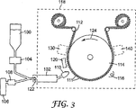
本開示の色シフティング再帰反射物品のミクロスフィアの層と光学的に関連する反射コーティングの好ましい製造方法は、図3に示されるコーティングプロセスの態様を含み得る。このプロセスは、任意に(例えば、クリーンな環境を提供するため、不活性雰囲気を提供するため、または他のかかる理由のため)チャンバー118中にコーティング領域を包囲しながら気圧下で、またはチャンバー118が真空チャンバーである減圧下で実行可能である。 A preferred method of manufacturing a reflective coating optically associated with the microsphere layer of the color shifting retroreflective article of the present disclosure may include the coating process embodiment shown in FIG. This process is optionally under atmospheric pressure, surrounding the coating region in the chamber 118 (eg, to provide a clean environment, to provide an inert atmosphere, or for other such reasons) Can be carried out under reduced pressure, which is a vacuum chamber.
図3に示されるように、色シフティング再帰反射物品112はチャンバー118中に提供される。色シフティング再帰反射物品112は、本明細書で記載されるようないずれかの適切な色シフティング再帰反射物品を含み得る。色シフティング再帰反射物品112は、例えば米国特許第6,355,302号明細書(ヴァンデンバーグ(Vandenberg)ら)に記載されるような担体フィルムに結合されたミクロスフィアの層を含み得る。ミクロスフィアの層はミクロスフィア111を含み得る。いくつかの実施形態において、物品112は、チャンバー118中での色シフティング再帰反射物品112の配置の前に形成される第1の反射層(例えば図2の第1の反射層22)を含み得る。あるいは、いずれかの適切な技術、例えば真空金属化、スパッタリング、蒸発、化学蒸着(CVD)およびプラスマCVDを使用して、ミクロスフィアの層に隣接する第1の反射層を堆積させるために、任意の堆積位置130(例えば金属化位置)がチャンバー118中に含まれてもよい。
As shown in FIG. 3, a color shifting
第1の反射層の堆積前に、ミクロスフィアの層への第1の反射層の接着を促進するためにミクロスフィアの層を処理してもよい。いずれかの適切な技術、例えばプラスマ処理、コロナ処理、炎処理またはUV/オゾン処理を使用してミクロスフィアの層を処理することができる。本明細書でさらに記載されるように、第1の反射層の堆積前にミクロスフィアの層上に一層以上の中間層をさらに形成してもよい。 Prior to the deposition of the first reflective layer, the microsphere layer may be treated to promote adhesion of the first reflective layer to the microsphere layer. The microsphere layer can be treated using any suitable technique, such as plasma treatment, corona treatment, flame treatment or UV / ozone treatment. As further described herein, one or more intermediate layers may be further formed on the microsphere layer prior to the deposition of the first reflective layer.
次いで、コーティング材料100を使用して、スペーサー層(例えば図2のスペーサー層24)を第1の反射層上に堆積させる。液体モノマーまたはプレポリマーの形態で供給されるコーティング材料100は、ポンプ104を通してエバポレーター102中に定量され得る。本明細書で詳述されるように、フラッシュ蒸発および担体ガス衝突蒸発を含むいくつかの技術の1つによって、コーティング材料100を蒸発させることができる。任意のノズル122を通してコーティング材料100を微細液滴に微粒化することが好ましく、そしてその後、液滴はエバポレーター102内部で蒸発される。任意に、コーティング材料100を微粒化するため、そしてノズル122を通してエバポレーター102中に液滴を指向するために担体ガス106を使用することが可能である。液体コーティング材料100または液体コーティング材料100の液滴の蒸発は、エバポレーター102の加熱された壁との接触、任意の担体ガス106(任意にヒーター108によって加熱されたもの)による接触、またいくつかのは他の加熱表面との接触によって実行され得る。液体コーティング材料100を蒸発させるためのいずれの適切な操作も、本開示における使用のために熟考される。
The
蒸発後、コーティングダイ110を通して、そして色シフティング再帰反射物品112の第1の反射層上へとコーティング材料100は指向され得る。第1の反射層の選択部分をコーティングするために、コーティングダイ110と色シフティング再帰反射物品112との間にマスク(図示せず)を任意に配置してもよい。任意に、グロー放電源、無音放電源、コロナ放電源等のような放電源120を使用して第1の反射層の表面を前処理することができる。前処理工程は、表面化学を変性するため、例えば第1の反射層へのコーティング材料100の接着力を改善するため、または他のかかる目的のために任意に実行される。加えて、本明細書で検討されるように、ミクロスフィアの層、第1の反射層の表面または両方を接着促進剤によって任意に前処理することができる。
After evaporation, the
色シフティング再帰反射物品112が、コーティングダイ110を出るモノマーまたはプレポリマー蒸気の凝縮温度以下の温度に維持されることが好ましい。色シフティング再帰反射物品112はドラム114の表面上に配置されるか、またはそれ以外の様式で一時的に関連して配置される。ドラム114は、層厚さを制御するように選択された速度で、再帰反射物品112がコーティングダイ110を通り越して移動するようにさせる。またドラム114は、プレポリマー蒸気の縮合温度以下に再帰反射物品112を維持するために適切なバイアス温度に維持され得る。物品112上での硬化材料100の凝縮後、液体モノマーまたはプレポリマー層を硬化してスペーサー層を形成することができる。材料の硬化は一般的に、可視光、紫外線放射、電子ビーム放射、イオン放射またはフリーラジカル(プラスマから)、あるいは加熱または他の適切な技術を使用して基材上で材料を照射する工程を含む。物品112を回転ドラム114上に取り付けた場合、コーティング材料100が連続的に適用され、そして第1の反射層の表面上で硬化されるように、放射線源116は好ましくはモノマーまたはプレポリマー蒸気源から下流に位置する。以前の回転間に析出および硬化された層上へモノマー蒸気を連続的に堆積および硬化するために、基材の複数の回転または流路を利用することができる。いくつかの実施形態において、本明細書でさらに記載されるように、スペーサー層上に第2の反射層が堆積された後にスペーサー層が硬化されてもよい。
The color shifting
放射線源116によってコーティング材料100を硬化して、スペーサー層を形成した後、色シフティング再帰反射物品112は任意の堆積位置140(例えば金属化位置)を通過する。ここでは、いずれかの適切な技術、例えば真空金属化、スパッタリング、蒸発、化学蒸着(CVD)およびプラスマCVDを使用して、第2の反射層(例えば図2の第2の反射層26)がスペーサー層上に堆積され得る。あるいはドラム114を逆転し、堆積位置130を利用することによって第2の反射層を堆積させてもよい。色シフティング再帰反射物品112をチャンバー118から取り出した後に、第2の反射層が堆積されてもよい。本明細書でさらに記載されるように、第2の反射層が堆積された後、ミクロスフィアの層とは反対側の反射コーティング上にバインダー層または基材を形成してもよい。
After curing the
当業者は、第1または第2の反射層を積層として適用するように図3に示される装置が改造されてもよいことを認識するだろう。ここでは積層の各々は、一種以上の無機または有機材料を含有しており、光を反射するようにかかる層の二層以上が十分に異なる屈折率を有する。また当業者は、所望により追加的なコーティング材料を適用するように図3に示される装置が改造されてもよいことを認識するだろう。例えば、スパッタリング、化学蒸着、電気めっき、溶媒からの凝縮および他のかかる方法を含む現在既知であるか、または今後開発される適切な方法を使用して、無機、有機金属化合物または非ポリマー層が堆積されてもよい。第1の反射層の堆積前、第1の反射層の堆積後、またはスペーサー層の堆積後、これらの追加的な層がミクロスフィアの層上に直接的に堆積されてもよい。 One skilled in the art will recognize that the apparatus shown in FIG. 3 may be modified to apply the first or second reflective layer as a stack. Here, each of the stacks contains one or more inorganic or organic materials, and two or more of such layers have sufficiently different refractive indices to reflect light. Those skilled in the art will also recognize that the apparatus shown in FIG. 3 may be modified to apply additional coating materials if desired. For example, inorganic, organometallic compounds or non-polymeric layers may be formed using suitable methods now known or later developed including sputtering, chemical vapor deposition, electroplating, condensation from solvents and other such methods. It may be deposited. These additional layers may be deposited directly on the microsphere layer prior to deposition of the first reflective layer, after deposition of the first reflective layer, or after deposition of the spacer layer.
いくつかの実施形態において、ミクロスフィアの層と反射コーティングとの間、または第1の反射層とスペーサー層との間に接着促進剤をコーティングすることができる。接着促進剤は、例えば、反射コーティングとミクロスフィアの層との間または第1の反射層とスペーサー層との間の中間層接着力を改善するために選択することができる。例えば、本開示の多層反射コーティングのポリマー層と、例えばガラスまたはセラミックのミクロスフィアであり得る光学素子との間の接着力を促進するシランカップリング剤が使用可能である。代表的なシランカップリング剤としては、アミノプロピルトリエトキシシラン、グリシドキシプロピルトリメトキシシラン、メタクリルオキシプロピルトリメトキシシランおよびビニルトリメトキシシランが挙げられる。また接着促進剤としてチタネートカップリング剤を使用することも可能であり、例としては、イソプロピルトリ(ジオクチル)ホスファトチタネート、ジメタクリルオキソエチレンチタネートおよびチタン(テトライソプロポキシド)が挙げられる。ヘキサメチルジシラザンのようなシラザンも接着促進剤として使用可能である。シランカップリング剤の例は、米国特許第5,200,262号明細書(リ(Li))に開示される。 In some embodiments, an adhesion promoter can be coated between the microsphere layer and the reflective coating, or between the first reflective layer and the spacer layer. Adhesion promoters can be selected, for example, to improve the interlayer adhesion between the reflective coating and the microsphere layer or between the first reflective layer and the spacer layer. For example, a silane coupling agent that promotes adhesion between the polymer layer of the multilayer reflective coating of the present disclosure and an optical element that can be, for example, a glass or ceramic microsphere can be used. Representative silane coupling agents include aminopropyltriethoxysilane, glycidoxypropyltrimethoxysilane, methacryloxypropyltrimethoxysilane, and vinyltrimethoxysilane. It is also possible to use titanate coupling agents as adhesion promoters, examples of which include isopropyl tri (dioctyl) phosphato titanate, dimethacryloxoethylene titanate and titanium (tetraisopropoxide). Silazanes such as hexamethyldisilazane can also be used as adhesion promoters. Examples of silane coupling agents are disclosed in US Pat. No. 5,200,262 (Li).
図3に示される方法の様々な態様を実行するために適切な装置は、例えば、フレミング(Fleming)ら‘564、ならびに米国特許第6,012,647号明細書(リヨンズ(Lyons)ら‘647);米国特許第6,045,864号明細書(リヨンズ(Lyons)ら‘864);米国特許第4,722,515号明細書(ハム(Ham));米国特許第4,842,893号明細書(イアリジス(Yializis)ら‘893);米国特許第4,954,371号明細書(イアリジス(Yializis)‘371);米国特許第5,097,800号明細書(ショー(Shaw)ら‘800)および米国特許第5,395,644号明細書(アフィニト(Affinito))に記載される。図3に示される方法のこれらおよび他の態様を実行するために適切であり得る装置および装置部分については、引用文献にさらに詳細に記載されている。 Suitable devices for carrying out the various aspects of the method shown in FIG. 3 include, for example, Fleming et al. '564, as well as US Pat. No. 6,012,647 (Lyons et al.' 647). U.S. Pat. No. 6,045,864 (Lyons et al. '864); U.S. Pat. No. 4,722,515 (Ham); U.S. Pat. No. 4,842,893. Specification (Yializis et al. '893); U.S. Pat. No. 4,954,371 (Yializis' 371); U.S. Pat. No. 5,097,800 (Shaw et al.') 800) and U.S. Pat. No. 5,395,644 (Affinito). Apparatus and apparatus parts that may be suitable for performing these and other aspects of the method shown in FIG. 3 are described in further detail in the cited references.
図3に示されるプロセスのために適切な代表的なモノマーおよびオリゴマーとしては、アクリレート、メタクリレート、アクリルアミド、メタクリルアミド、ビニルエーテル、マレエート、シンナメート、スチレン、オレフィン、ビニル、エポキシド、シラン、メラミン、ヒドロキシ官能性モノマーおよびアミノ官能性モノマーが挙げられる。適切なモノマーおよびオリゴマーは2個以上の反応基を有し得、そしてこれらの反応基は同一分子上で異なる化学特性のものであってもよい。反射コーティングの一層以上における所望の屈折率のような広範囲の光学的特性を達成するために、プレポリマーを混合することができる。その表面上に化学的反応種を既に有する基材上へ蒸気相から反応性材料をコーティングすることも有用であり得る。かかる反応種の例としては、モノマー、オリゴマー、開始剤、触媒、水、またはヒドロキシ、カルボン酸、イソシアネート、アクリレート、メタクリレート、ビニル、エポキシ、シリル、スチリル、アミノ、メラミンおよびアルデヒドのような反応基が挙げられる。熱的に、または放射線硬化よって、化学特性に応じて開始剤および触媒化学を用いて、または場合によっては開始剤または触媒を使用せずに、これらの反応を開始することが可能である。二種以上のプレポリマー出発材料が使用される場合、成分を一緒に蒸発および析出させてもよいが、それらを別々の蒸発源から蒸発させることもできる。 Representative monomers and oligomers suitable for the process shown in FIG. 3 include acrylate, methacrylate, acrylamide, methacrylamide, vinyl ether, maleate, cinnamate, styrene, olefin, vinyl, epoxide, silane, melamine, hydroxy functionality Monomers and amino functional monomers. Suitable monomers and oligomers can have more than one reactive group, and these reactive groups may be of different chemical properties on the same molecule. The prepolymer can be mixed to achieve a wide range of optical properties, such as the desired refractive index in one or more of the reflective coatings. It may also be useful to coat the reactive material from the vapor phase onto a substrate that already has chemically reactive species on its surface. Examples of such reactive species include monomers, oligomers, initiators, catalysts, water, or reactive groups such as hydroxy, carboxylic acid, isocyanate, acrylate, methacrylate, vinyl, epoxy, silyl, styryl, amino, melamine and aldehyde. Can be mentioned. It is possible to initiate these reactions thermally or by radiation curing, with or without initiator and catalyst chemistry depending on the chemical properties. If two or more prepolymer starting materials are used, the components may be evaporated and precipitated together, but they can also be evaporated from separate evaporation sources.
堆積されたプレポリマー材料は実質的に均一な、実質的に連続的な様式で適用可能であるが、それらは、例えば、光学素子の選択部分のみをカバーする島構造として不連続な様式でも適用可能である。例えば、望ましくない部分のその後の除去工程を含むマスクまたは他の適切な技術を使用することによって、文字、数字または他の兆候の形態で不連続な適用を提供することができる。 The deposited prepolymer materials can be applied in a substantially uniform, substantially continuous manner, but they can also be applied in a discontinuous manner, for example as an island structure covering only selected parts of the optical element Is possible. For example, a discontinuous application can be provided in the form of letters, numbers or other signs by using a mask or other suitable technique that includes a subsequent removal step of unwanted portions.
プレポリマー蒸着は、約0.01μm〜約50μmの厚さを有する薄フィルムを形成するために特に有用である。蒸気への基材の暴露時間を増加させることによって、アトマイザーへの流体組成物の流速を増加させることによって、または複数の流路上でコーティング材料に基材を暴露することによって、より厚い層を形成することができる。蒸気への再帰反射物品の暴露時間を増加させることは、系に複数の蒸気源を加えることによって、または物品が系を進行する速度を減少させることによって達成され得る。異なる材料の積層コーティングは、各堆積で異なるコーティング材料を使用する連続的なコーティング堆積によって、または基材進行経路に沿って互いに離された異なる供給源から材料を同時に堆積させることによって形成され得る。 Prepolymer deposition is particularly useful for forming thin films having a thickness of about 0.01 μm to about 50 μm. Form a thicker layer by increasing the exposure time of the substrate to the vapor, increasing the flow rate of the fluid composition to the atomizer, or by exposing the substrate to the coating material on multiple channels can do. Increasing the exposure time of the retroreflective article to the vapor can be accomplished by adding multiple vapor sources to the system or by reducing the rate at which the article travels through the system. Laminated coatings of different materials can be formed by sequential coating deposition using different coating materials for each deposition, or by simultaneously depositing materials from different sources separated from each other along the substrate travel path.
本明細書に記載される色シフティング物品のいくつかのミクロスフィアの各々に関して不均一な厚さを含むスペーサー層を製造するために、様々な技術が使用されてもよい。1つのかかる代表的な技術は、直接的に異なる厚さで異なる量のモノマーを凝縮することである。かかる技術は、例えばショー(Shaw)ら‘895に記載される。あるいは均一な厚さのモノマーが全ての領域で堆積されて、次いで、各ミクロスフィアに関して異なる領域で異なる範囲までスペーサー層の厚さが収縮してもよい。スペーサー層の重合度を制御することによって、スペーサー層の厚さを制御してもよい。かかる技術についても、例えばショー(Shaw)ら‘895にさらに記載される。 Various techniques may be used to produce a spacer layer that includes a non-uniform thickness for each of several microspheres of the color shifting article described herein. One such representative technique is to condense different amounts of monomer directly at different thicknesses. Such techniques are described, for example, in Shaw et al. '895. Alternatively, a uniform thickness of monomer may be deposited in all areas, and then the spacer layer thickness may shrink to different ranges in different areas for each microsphere. The thickness of the spacer layer may be controlled by controlling the degree of polymerization of the spacer layer. Such techniques are also described further in, for example, Shaw et al. '895.
様々な方法を使用して、スペーサー層を形成するために配置され得るポリマーおよびプレポリマー材料のいくつかの例を表Iに記載する。各材料に関して、モノマーまたはモノマーから製造されるポリマーの既知の屈折率を示す。所望の屈折率を有するか、または所望の屈折率を得るために一種以上の他の材料と混合することができるこれらまたは他の出発材料を選択することによって、異なる屈折率を達成することができる。適切な他のポリマーは、例えばフレミング(Fleming)ら‘564に開示される。 Some examples of polymers and prepolymer materials that can be arranged to form the spacer layer using various methods are listed in Table I. For each material, the known refractive index of the monomer or polymer made from the monomer is shown. Different refractive indices can be achieved by selecting these or other starting materials that have the desired refractive index or that can be mixed with one or more other materials to obtain the desired refractive index. . Other suitable polymers are disclosed, for example, in Fleming et al. '564.

開示された色シフティング再帰反射物品は、様々な用途において使用可能である。例えば、この物品は、車両用識別バッジ、広告または信号において使用するための装飾効果を提供し得る。改ざんの証拠または安全証明を提供するために、この物品をパスポート、免許証または身分証明書のような基材に添付することができる。この物品は、再帰反射光の色に基づく位置情報を提供し得る。この物品は、再帰反射光の色における視覚的に知覚され得る変化が情報のため、または他の目的のために所望される場合はいずれも、当業者にとって明白である他の用途を有し得る。 The disclosed color shifting retroreflective article can be used in a variety of applications. For example, the article may provide a decorative effect for use in a vehicle identification badge, advertisement or signal. This article can be attached to a substrate, such as a passport, license or identification card, to provide tamper evidence or safety proof. The article may provide position information based on the color of the retroreflected light. The article may have other uses that will be apparent to those skilled in the art whenever a visually perceptible change in the color of the retroreflected light is desired for information or for other purposes. .
以下の非限定的な実施例を参照することによって本発明を説明する。特記されない限り、ここでは全ての部およびパーセントは重量による。 The invention is illustrated by reference to the following non-limiting examples. All parts and percentages herein are by weight unless otherwise specified.
ミクロスフィアの層を有するビーズコート(beadcoat)担体を形成するポリエステルフィルム担体上で、1.93の屈折率および60μmの公称直径を有する高屈折率ガラスビーズをポリエチレン層中に部分的に包埋した。3つの別々のコーティング流路中でミクロスフィアの層上に反射コーティングを形成した。各コーティング流路間でチャンバーを空気に開放した。真空チャンバー中にビーズコート担体を装填し、圧力は2.7×10⁻⁵トルまで低下した。最初に100ワット電力で窒素プラスマによってビーズコートをプラスマ処理し、次いで12,250ワット電力を使用して、アルゴンガスによって4nm(標的厚さ)クロム層をスパッタコーティングし、半透明の第1の反射金属層を形成した。標的ライン速度は約15メートル/分(50フィート/分)であったが、実際の速度は外見上の遅延のため約12メートル/分(40フィート/分)であった。真空チャンバーを開放し、クロムの第1の反射金属層を有するビーズコート担体の点検を可能にした。次いで担体を真空チャンバー中に再充填し、圧力は3.5×10-6トルまで低下した。50フィート/分のウェブ速度で600nmのアクリレートスペーサー層を堆積させた。このアクリレートスペーサー層は、48.5%のIRR−214環式ジアクリレート(UCB ケミカルズ(UCB Chemicals)から)、48.5%のラウリルアクリレートおよび3%のエベクリル(EBECRYL)(登録商標)170アクリル化酸性化合物(UCB ケミカルズ(UCB Chemicals)から)を含有する混合物から形成された。第3の流路において、抵抗加熱された蒸発ボートから30nmのアルミニウムを蒸着して、第2の反射金属層を形成した。 A high refractive index glass bead having a refractive index of 1.93 and a nominal diameter of 60 μm was partially embedded in a polyethylene layer on a polyester film carrier forming a beadcoat carrier having a layer of microspheres. . A reflective coating was formed on the microsphere layer in three separate coating channels. The chamber was opened to air between each coating channel. The bead coat carrier was loaded into the vacuum chamber and the pressure dropped to 2.7 × 10 −5 Torr. First, the bead coat is plasma treated with nitrogen plasma at 100 watts power, then sputter coated with a 4 nm (target thickness) chromium layer with argon gas using 12,250 watts power to produce a translucent first reflection. A metal layer was formed. The target line speed was about 15 meters / minute (50 feet / minute), but the actual speed was about 12 meters / minute (40 feet / minute) due to the apparent delay. The vacuum chamber was opened to allow inspection of the bead coat carrier with the first reflective metal layer of chromium. The carrier was then refilled into the vacuum chamber and the pressure dropped to 3.5 × 10 −6 torr. A 600 nm acrylate spacer layer was deposited at a web speed of 50 feet / min. This acrylate spacer layer is 48.5% IRR-214 cyclic diacrylate (from UCB Chemicals), 48.5% lauryl acrylate and 3% EBECRYL® 170 acrylated. Formed from a mixture containing acidic compounds (from UCB Chemicals). In the third channel, 30 nm of aluminum was evaporated from a resistance-heated evaporation boat to form a second reflective metal layer.
ビーズコート担体上に配置された色シフティング再帰反射物品に、ポリウレタン接着剤バインダー層を適用した。ソルベー ケミカルズ(Solvay Chemicals)からの、エプシロン−カプロラクトンとポリ(1,4−ブチレングリコールとのCAPA(登録商標)720(現在はCAPA7201A) ブロックコポリマー 10.6グラム;ミリケン コーポレイション(Milliken Corporation)からのSYN FAC(登録商標)8009 アルコキシレート 18.0グラム;パーストープ インコーポレイテッド(Perstorp Inc.)からのパーストープ(PERSTORP)(登録商標)TP30 アクリル酸 3.4グラム;ジブチルスズジラウレート 3滴;バイエル コーポレイション(Bayer Corp.)からのモンデュア(MONDUR)(登録商標)ML ジフェニルメタンジイソシアネートと、CAPA720 ブロックコポリマーとを4:1のモル比で反応することによって製造されたポリウレタンプレポリマー 60.4グラム;およびシラン接着促進剤 4.6グラムを混合することによって接着剤バインダー層を製造した。シラン接着促進剤は、ヴィトコ コーポレイション(Witco Corp.)からのA074 アミノプロピルメチルジエトキシシラン 3.05部およびプロピレンカーボネート 1.625部を反応させることによって合成されたジエトキシシラン 2.44グラムと、ヴィトコ コーポレイション(Witco Corp.)からのA1100 アミノプロピルトリエトキシシラン 3.63部およびプロピレンカーボネート 1.675部を反応させることによって合成されたトリエトキシシラン 2.46グラムとの混合物から製造された。0.15mm(6ミル)隙間で設定されたノッチバーコーターによって、得られた反応性ポリウレタン混合物をコーティングし、そして66℃で3分間硬化させ、次いで半硬化された接着剤上に100%ポリエステル布基材を適用し、104℃で10分間硬化させた。4週間後、ポリエステルフィルム基材を取り除き、露出レンズ色シフティング再帰反射物品を得た。周辺光条件下で、この材料は灰色がかった青緑色の外観を有した。再帰反射において、この材料は青または緑に見えるが、試料配向をシフトすると緑または青にシフトした。再帰反射係数(Ra)は、0.2°の観測角度および−4°の入口角で214であった。および。25回の家庭用洗濯機サイクルの後、この試料は本来のRaの50%より高い値を保持した。 A polyurethane adhesive binder layer was applied to the color shifting retroreflective article placed on the bead coat carrier. 10.6 grams of CAPA® 720 (now CAPA7201A) block copolymer of epsilon-caprolactone and poly (1,4-butylene glycol) from Solvay Chemicals; SYN from Milliken Corporation FAC® 8009 alkoxylate 18.0 grams; Perstorp® TP30 acrylic acid from Perstorp Inc. 3.4 grams; dibutyltin dilaurate 3 drops; Bayer Corp. ) Mondur (registered trademark) ML diphenylmethane diisocyanate from The adhesive binder layer by mixing 60.4 grams of a polyurethane prepolymer prepared by reacting a salt with a CAPA720 block copolymer in a 4: 1 molar ratio; and 4.6 grams of a silane adhesion promoter. The silane adhesion promoter was diethoxysilane 2.44 synthesized by reacting 3.05 parts A074 aminopropylmethyldiethoxysilane and 1.625 parts propylene carbonate from Witco Corp. Triethoxysila synthesized by reacting Gram with 3.63 parts A1100 aminopropyltriethoxysilane and 1.675 parts propylene carbonate from Witco Corp. The resulting reactive polyurethane mixture was coated with a notch bar coater set at 0.15 mm (6 mil) gap and cured at 66 ° C. for 3 minutes, A 100% polyester fabric substrate was then applied over the semi-cured adhesive and cured for 10 minutes at 104 ° C. After 4 weeks, the polyester film substrate was removed to provide an exposed lens color shifting retroreflective article. Under ambient light conditions, the material had an greyish turquoise appearance.In retroreflection, the material appeared blue or green, but shifted to green or blue when the sample orientation was shifted. (Ra) was 214 at an observation angle of 0.2 ° and an entrance angle of −4 °. and. After 25 home washing machine cycles, the sample retained a value higher than 50% of the original Ra.
図4は、実施例の色シフティング再帰反射物品に関してCIE x−y色度座標を使用する色度図である。色シフティング再帰反射物品の約21cm×24cmの領域について、CIE 2°オブザーバーおよび発光物Aを使用して試験した。観測角度を夜間の色測定の通常値である0.33°に固定し、そして入口角を2°の間隔で0から60°まで変化させた。夜間の色に関して得られたCIE色座標は、黄緑色、緑色、青色、すみれ色、紫色、ピンク色、オレンジ色、そして最終的に白色から滑らかな連続スパイラル状曲線で変化する。一回で試験された試料領域上の変動のため、これらの値は実際に、いくつかの色シフティングの平均である。 FIG. 4 is a chromaticity diagram using CIE xy chromaticity coordinates for an example color shifting retroreflective article. An area of about 21 cm × 24 cm of the color shifting retroreflective article was tested using a CIE 2 ° observer and phosphor A. The observation angle was fixed at 0.33 °, the normal value for nighttime color measurements, and the entrance angle was varied from 0 to 60 ° at 2 ° intervals. The CIE color coordinates obtained for nighttime colors vary from yellowish green, green, blue, violet, purple, pink, orange, and finally from white to a smooth continuous spiral curve. These values are actually the average of several color shifting due to variations on the sample area tested at one time.
図5は、走査型電子顕微鏡を使用して撮影された実施例の色シフティング再帰反射物品の一部分の写真である。コーティングされたガラスミクロスフィアの横断面を走査型電子顕微鏡で試験した。図5は、ミクロスフィアの層上で形成された反射コーティングを示す。コーティングは非常に薄く、ビーズの表面構造の輪郭を示し、そして標的厚さに近い。図5に示されるように、反射コーティングは各ミクロスフィアと関連する不均一な厚さを含む。 FIG. 5 is a photograph of a portion of an example color shifting retroreflective article taken using a scanning electron microscope. The cross-section of the coated glass microsphere was examined with a scanning electron microscope. FIG. 5 shows a reflective coating formed on a layer of microspheres. The coating is very thin, outlines the surface structure of the beads and is close to the target thickness. As shown in FIG. 5, the reflective coating includes a non-uniform thickness associated with each microsphere.
本明細書に引用される全ての文献は、本開示へのそれら全部の参照によって本明細書に明白に援用される。本開示の実施形態の実例が検討され、そして本開示の範囲内で可能な変形について参照された。本開示におけるこれらおよび他の変形および修正は、本開示の範囲から逸脱することなく当業者にとって明白であり、そして本開示は本明細書で明らかにされた実施形態の実例に限定されないことは理解されるべきである。従って、本発明は添付の請求の範囲によってのみ限定される。 All references cited herein are expressly incorporated herein by reference in their entirety to the present disclosure. Examples of embodiments of the present disclosure have been discussed and reference has been made to possible variations within the scope of the present disclosure. These and other variations and modifications in this disclosure will be apparent to those skilled in the art without departing from the scope of this disclosure, and it is understood that this disclosure is not limited to the examples of embodiments disclosed herein. It should be. Accordingly, the invention is limited only by the following claims.
Claims (3)
ミクロスフィアの層と光学的に関連して配置された反射コーティングと、
を含んでなる色シフティング再帰反射物品であって、
反射コーティングが、半透明の第1の反射層と第2の反射層との間に配置された少なくとも部分的に透明のスペーサー層を含んでなり、そして第1の方向から物品上に入射する光が第1の色で再帰反射され、そして第2の方向から物品上に入射する光が、第1の色とは視覚的に異なる第2の色で再帰反射されるように、反射コーティングの少なくとも一層が複数のミクロスフィアの各々と関連する不均一な厚さを備える、色シフティング再帰反射物品。A layer of microspheres,
A reflective coating disposed in optical association with the layer of microspheres;
A color shifting retroreflective article comprising
The reflective coating comprises an at least partially transparent spacer layer disposed between the translucent first reflective layer and the second reflective layer, and light incident on the article from the first direction At least of the reflective coating so that light incident on the article from the second direction is retroreflected with a second color that is visually different from the first color. A color shifting retroreflective article, wherein the layer comprises a non-uniform thickness associated with each of the plurality of microspheres.
ミクロスフィアの層と光学的に関連して配置された反射コーティングと、
を含んでなる色シフティング再帰反射物品であって、
反射コーティングが、
ミクロスフィアの層に隣接する半透明の第1の反射層と、
第1の反射層に隣接する少なくとも部分的に透明のスペーサー層と、
スペーサー層が第1の反射層と第2の反射層との間にあるようにスペーサー層に隣接する第2の反射層と、
を含んでなり、
反射コーティングが可視光を不均一に反射し、そして少なくとも複数のミクロスフィアの各ミクロスフィアと関連する反射コーティングの予め定められた第1の領域が第1の厚さを備え、そして少なくとも複数のミクロスフィアの各ミクロスフィアと関連する反射コーティングの予め定められた第2の領域が、第1の厚さとは異なる第2の厚さを備える、色シフティング再帰反射物品。A layer of microspheres,
A reflective coating disposed in optical association with the layer of microspheres;
A color shifting retroreflective article comprising
Reflective coating
A translucent first reflective layer adjacent to the microsphere layer;
An at least partially transparent spacer layer adjacent to the first reflective layer;
A second reflective layer adjacent to the spacer layer such that the spacer layer is between the first reflective layer and the second reflective layer;
Comprising
The reflective coating non-uniformly reflects visible light, and a predetermined first region of the reflective coating associated with each microsphere of at least a plurality of microspheres comprises a first thickness, and at least a plurality of microspheres A color shifting retroreflective article, wherein a predetermined second region of the reflective coating associated with each microsphere of the sphere comprises a second thickness that is different from the first thickness.
ミクロスフィアの層と光学的に関連する反射コーティングを形成する工程と、
を含んでなる色シフティング再帰反射物品の製造方法であって、
反射コーティングを形成する工程が
ミクロスフィアの層に隣接する半透明の第1の反射層を堆積させる工程と、
第1の反射層上で少なくとも部分的に透明のスペーサー層を堆積させる工程と、
スペーサー層上で第2の反射層を堆積させる工程と、
を含んでなり、
第1の方向から物品上に入射する光が第1の色で再帰反射され、そして第2の方向から物品に入射する光が、第1の色とは視覚的に異なる第2の色で再帰反射されるように、複数のミクロスフィアの各々に反射コーティングの各層の少なくとも一層における不均一な厚さを提供するように反射コーティングが形成される、色シフティング再帰反射物品の製造方法。Providing a microsphere layer;
Forming a reflective coating optically associated with the layer of microspheres;
A method for producing a color-shifting retroreflective article comprising
Forming a reflective coating comprises depositing a translucent first reflective layer adjacent to the layer of microspheres;
Depositing an at least partially transparent spacer layer on the first reflective layer;
Depositing a second reflective layer on the spacer layer;
Comprising
Light incident on the article from the first direction is retroreflected in a first color, and light incident on the article from the second direction is recursed in a second color that is visually different from the first color. A method of manufacturing a color shifting retroreflective article, wherein a reflective coating is formed to provide a non-uniform thickness in at least one of each layer of the reflective coating to each of the plurality of microspheres to be reflected.
Applications Claiming Priority (3)
| Application Number | Priority Date | Filing Date | Title |
|---|---|---|---|
| US53396203P | 2003-12-30 | 2003-12-30 | |
| US60/533,962 | 2003-12-30 | ||
| PCT/US2004/043549 WO2005066667A1 (en) | 2003-12-30 | 2004-12-28 | Color shifting retroreflector and method of making same |
Publications (3)
| Publication Number | Publication Date |
|---|---|
| JP2007517265A JP2007517265A (en) | 2007-06-28 |
| JP2007517265A5 JP2007517265A5 (en) | 2008-02-28 |
| JP4787173B2 true JP4787173B2 (en) | 2011-10-05 |
Family
ID=34748982
Family Applications (1)
| Application Number | Title | Priority Date | Filing Date |
|---|---|---|---|
| JP2006547445A Expired - Fee Related JP4787173B2 (en) | 2003-12-30 | 2004-12-28 | Color-shifting retroreflector and method for manufacturing the same |
Country Status (7)
| Country | Link |
|---|---|
| US (1) | US7140741B2 (en) |
| EP (1) | EP1700142A1 (en) |
| JP (1) | JP4787173B2 (en) |
| KR (1) | KR101088562B1 (en) |
| BR (1) | BRPI0418341A (en) |
| TW (1) | TW200535458A (en) |
| WO (1) | WO2005066667A1 (en) |
Families Citing this family (36)
| Publication number | Priority date | Publication date | Assignee | Title |
|---|---|---|---|---|
| WO2006044305A1 (en) * | 2004-10-15 | 2006-04-27 | Dow Global Technologies Inc. | An isocyanate-terminated prepolymer composition and a polyurethane or polyurea elastomer produced therefrom |
| WO2008007394A1 (en) * | 2006-07-10 | 2008-01-17 | Fabio Valle | Process for applying refracting and reflecting spheres and/or microspheres on surfaces and product obtained therewith |
| US8120854B2 (en) * | 2006-12-28 | 2012-02-21 | 3M Innovative Properties Company | Interference films having acrylamide layer and method of making same |
| EP2169434B1 (en) * | 2007-06-19 | 2016-10-19 | Marujin Co., Ltd. | Iridescent reflected light emitting retroreflective material |
| DE102007032666A1 (en) | 2007-07-13 | 2009-01-22 | Bayer Materialscience Ag | Allophanate and silane-containing polyisocyanates |
| US8083359B2 (en) | 2007-11-20 | 2011-12-27 | Mks Instruments, Inc. | Corner cube retroreflector mount |
| KR20110041507A (en) | 2008-07-10 | 2011-04-21 | 쓰리엠 이노베이티브 프로퍼티즈 컴파니 | Viscoelastic lightguide |
| WO2010005810A2 (en) | 2008-07-10 | 2010-01-14 | 3M Innovative Properties Company | Retroreflective articles and devices having viscoelastic lightguide |
| CN102138087B (en) | 2008-07-10 | 2017-03-01 | 3M创新有限公司 | There is retroreflective articles and the device of viscoelastic lightguide |
| US9285531B2 (en) | 2008-08-08 | 2016-03-15 | 3M Innovative Properties Company | Lightguide having a viscoelastic layer for managing light |
| EP2393655A4 (en) * | 2009-02-06 | 2017-07-26 | 3M Innovative Properties Company | Light control film and multi-layer optical film stack |
| JP2013516789A (en) | 2010-01-06 | 2013-05-13 | ダウ グローバル テクノロジーズ エルエルシー | Moisture resistant photovoltaic device having an elastomeric polysiloxane protective layer |
| WO2011100277A1 (en) | 2010-02-10 | 2011-08-18 | 3M Innovative Properties Company | Illumination device having viscoelastic layer |
| BR112012028904A2 (en) | 2010-05-25 | 2016-07-26 | 3M Innovative Properties Co | retroreflective article of exposed lenses |
| EP2580619B1 (en) | 2010-06-10 | 2019-07-24 | 3M Innovative Properties Company | Display device and method of lc panel protection |
| US8659829B2 (en) | 2010-08-05 | 2014-02-25 | 3M Innovative Properties Company | Multilayer film comprising matte surface layer and articles |
| DE102010052665A1 (en) | 2010-11-26 | 2012-05-31 | Giesecke & Devrient Gmbh | Reflective security element for security paper, value documents or the like |
| JP5558591B2 (en) * | 2011-01-19 | 2014-07-23 | 日本カーバイド工業株式会社 | A micro glass sphere retroreflective sheet on which images with viewing directionality are installed |
| TW201315598A (en) * | 2012-10-18 | 2013-04-16 | Cing Wai Kung Mau Company | Process for reflective products |
| CN106415336B (en) * | 2014-04-30 | 2020-12-04 | 3M创新有限公司 | Stain resistant retroreflective article |
| WO2016022940A1 (en) * | 2014-08-08 | 2016-02-11 | 3M Innovative Properties Company | Retroreflective elements including particles |
| JP5766343B1 (en) * | 2014-10-24 | 2015-08-19 | ユニチカスパークライト株式会社 | Retroreflective material |
| EP3582642A4 (en) | 2017-02-20 | 2021-01-13 | 3M Innovative Properties Company | Optical articles and systems interacting with the same |
| US20180320859A1 (en) * | 2017-05-04 | 2018-11-08 | Case-Mate, Inc. | Electronics case with light-reflective elements |
| WO2019064108A1 (en) | 2017-09-27 | 2019-04-04 | 3M Innovative Properties Company | Personal protective equipment management system using optical patterns for equipment and safety monitoring |
| EP3701296A4 (en) * | 2017-10-27 | 2021-07-28 | 3M Innovative Properties Company | Exposed-lens retroreflective article comprising localized color layers |
| KR20200065062A (en) | 2017-10-27 | 2020-06-08 | 쓰리엠 이노베이티브 프로퍼티즈 캄파니 | Retroreflective article comprising a retroreflective element comprising a primary reflective layer and a secondary reflective layer |
| WO2019084302A1 (en) | 2017-10-27 | 2019-05-02 | 3M Innovative Properties Company | Retroreflective article comprising embedded reflective layers |
| US11366252B2 (en) | 2017-10-27 | 2022-06-21 | 3M Innovative Properties Company | Retroreflective article comprising locally-laminated reflective layers |
| WO2019084287A1 (en) * | 2017-10-27 | 2019-05-02 | 3M Innovative Properties Company | Exposed-lens retroreflective article comprising color layers comprising bi-layer structures |
| CN111801605A (en) | 2017-12-13 | 2020-10-20 | 3M创新有限公司 | High transmittance light control film |
| US11885989B2 (en) | 2017-12-13 | 2024-01-30 | 3M Innovative Properties Company | High transmission light control film |
| US11752729B2 (en) | 2018-07-17 | 2023-09-12 | 3M Innovative Properties Company | Conformable color shifting laminates |
| WO2020026139A1 (en) | 2018-08-01 | 2020-02-06 | 3M Innovative Properties Company | High transmission light control film |
| CN113994241A (en) | 2019-06-12 | 2022-01-28 | 3M创新有限公司 | Coated substrate comprising a dry aqueous dispersion of conductive particles and an organic polymer |
| US20220221624A1 (en) | 2019-06-12 | 2022-07-14 | 3M Innovative Properties Company | High transmission light control films with asymmetric light output |
Citations (3)
| Publication number | Priority date | Publication date | Assignee | Title |
|---|---|---|---|---|
| JPH0545507A (en) * | 1991-08-09 | 1993-02-23 | Minnesota Mining & Mfg Co <3M> | Film for decoration |
| JP2001318214A (en) * | 2000-05-10 | 2001-11-16 | Unitika Sparklight Kk | Retroreflecting material |
| JP2003512643A (en) * | 1999-10-15 | 2003-04-02 | スリーエム イノベイティブ プロパティズ カンパニー | Articles exhibiting dry and wet retroreflectivity |
Family Cites Families (49)
| Publication number | Priority date | Publication date | Assignee | Title |
|---|---|---|---|---|
| US1175224A (en) | 1916-03-14 | Pboces of | ||
| US2461011A (en) | 1945-08-29 | 1949-02-08 | Minnesota Mining & Mfg | Carbon powder method of making glass beads |
| US2853393A (en) | 1951-07-05 | 1958-09-23 | Minnesota Mining & Mfg | High-index glass elements |
| US2726161A (en) | 1953-09-21 | 1955-12-06 | Minnesota Mining & Mfg | High-index glass elements |
| US2842446A (en) | 1954-12-27 | 1958-07-08 | Minnesota Mining & Mfg | High-index glass elements |
| US2870030A (en) | 1955-07-18 | 1959-01-20 | Minnesota Mining & Mfg | High-index glass elements |
| US2965921A (en) | 1957-08-23 | 1960-12-27 | Flex O Lite Mfg Corp | Method and apparatus for producing glass beads from a free falling molten glass stream |
| US2992122A (en) | 1959-02-16 | 1961-07-11 | Minnesota Mining & Mfg | Light filtering high-index glass elements |
| US2939797A (en) | 1959-04-20 | 1960-06-07 | Prismo Safety Corp | Glass compositions |
| LU48072A1 (en) | 1965-02-24 | 1966-08-24 | ||
| US3700478A (en) | 1970-11-09 | 1972-10-24 | Minnesota Mining & Mfg | Microspheres having an antireflection coating and their use |
| US3700305A (en) | 1970-12-14 | 1972-10-24 | Minnesota Mining & Mfg | Retroreflective microspheres having a dielectric mirror on a portion of their surface and retroreflective constructions containing such microspheres |
| US3858977A (en) | 1972-01-18 | 1975-01-07 | Canadian Patents Dev | Optical interference authenticating means |
| US3946130A (en) | 1974-04-01 | 1976-03-23 | Minnesota Mining And Manufacturing Company | Transparent glass microspheres and products made therefrom |
| US4023889A (en) * | 1975-02-24 | 1977-05-17 | Morgan Adhesives Company | Retroreflective laminate |
| US4099838A (en) * | 1976-06-07 | 1978-07-11 | Minnesota Mining And Manufacturing Company | Reflective sheet material |
| US4082246A (en) | 1976-07-21 | 1978-04-04 | Dresser Industries, Inc. | Butterfly valve thruport seal |
| US4082426A (en) * | 1976-11-26 | 1978-04-04 | Minnesota Mining And Manufacturing Company | Retroreflective sheeting with retroreflective markings |
| US4367919A (en) | 1977-08-01 | 1983-01-11 | Minnesota Mining And Manufacturing Company | Durable glass elements |
| US4192576A (en) | 1978-11-20 | 1980-03-11 | Minnesota Mining And Manufacturing Company | Ultra-high-index glass microspheres and products made therefrom |
| US4648932A (en) | 1983-04-11 | 1987-03-10 | Minnesota Mining And Manufacturing Company | High-angularity retroreflective sheeting and method for manufacture |
| US4842893A (en) | 1983-12-19 | 1989-06-27 | Spectrum Control, Inc. | High speed process for coating substrates |
| US5097800A (en) | 1983-12-19 | 1992-03-24 | Spectrum Control, Inc. | High speed apparatus for forming capacitors |
| US4564556A (en) | 1984-09-24 | 1986-01-14 | Minnesota Mining And Manufacturing Company | Transparent non-vitreous ceramic particulate |
| US4722515A (en) | 1984-11-06 | 1988-02-02 | Spectrum Control, Inc. | Atomizing device for vaporization |
| US4772511A (en) | 1985-11-22 | 1988-09-20 | Minnesota Mining And Manufacturing Company | Transparent non-vitreous zirconia microspheres |
| AU586300B2 (en) | 1986-01-13 | 1989-07-06 | Minnesota Mining And Manufacturing Company | Pavement markings containing transparent non-vitreous ceramic microspheres |
| US4954371A (en) | 1986-06-23 | 1990-09-04 | Spectrum Control, Inc. | Flash evaporation of monomer fluids |
| US4775511A (en) * | 1986-07-08 | 1988-10-04 | William Kono | Method of sulfide tarnish inhibiting of silver-copper, silver-gold and silver-copper-gold alloys |
| US4763985A (en) | 1986-08-01 | 1988-08-16 | Minnesota Mining And Manufacturing Company | Retroreflective sheet with enhanced brightness |
| US4896943A (en) | 1987-05-13 | 1990-01-30 | Minnesota Mining And Manufacturing Company | Encapsulated-lens retroreflective sheeting having improved cover film |
| US5066098A (en) | 1987-05-15 | 1991-11-19 | Minnesota Mining And Manufacturing Company | Cellular encapsulated-lens high whiteness retroreflective sheeting with flexible cover sheet |
| US5200262A (en) | 1992-04-01 | 1993-04-06 | Minnesota Mining And Manufacturing Company | Launderable retroreflective applique with improved retention of retroreflective elements |
| US5260095A (en) | 1992-08-21 | 1993-11-09 | Battelle Memorial Institute | Vacuum deposition and curing of liquid monomers |
| US6083628A (en) | 1994-11-04 | 2000-07-04 | Sigma Laboratories Of Arizona, Inc. | Hybrid polymer film |
| US5877895A (en) | 1995-03-20 | 1999-03-02 | Catalina Coatings, Inc. | Multicolor interference coating |
| JP3629297B2 (en) | 1995-05-11 | 2005-03-16 | ミネソタ マイニング アンド マニュファクチャリング カンパニー | Retroreflective sheet and article having retroreflective performance |
| WO1997001776A1 (en) | 1995-06-29 | 1997-01-16 | Minnesota Mining & Mfg | Rainbow sheeting having distinct color changes and/or hidden images |
| US5674605A (en) | 1995-09-15 | 1997-10-07 | Minnesota Mining And Manufacturing Company | Retroreflective transfer sheet and applique |
| US5812317A (en) | 1995-10-26 | 1998-09-22 | Minnesota Mining And Manufacturing Company | Exposed lens retroreflective article having a polymeric intermediate layer disposed between microspheric and reflective layers |
| US5976669A (en) | 1996-12-20 | 1999-11-02 | 3M Innovative Properties Company | Retroreflective article having launderably durable bead-bond |
| US6045864A (en) | 1997-12-01 | 2000-04-04 | 3M Innovative Properties Company | Vapor coating method |
| US6012647A (en) | 1997-12-01 | 2000-01-11 | 3M Innovative Properties Company | Apparatus and method of atomizing and vaporizing |
| US6024455A (en) | 1998-01-13 | 2000-02-15 | 3M Innovative Properties Company | Reflective article with concealed retroreflective pattern |
| US6172810B1 (en) * | 1999-02-26 | 2001-01-09 | 3M Innovative Properties Company | Retroreflective articles having polymer multilayer reflective coatings |
| US6503564B1 (en) | 1999-02-26 | 2003-01-07 | 3M Innovative Properties Company | Method of coating microstructured substrates with polymeric layer(s), allowing preservation of surface feature profile |
| WO2000079315A1 (en) | 1999-06-17 | 2000-12-28 | 3M Innovative Properties Company | Retroreflective article having a colored layer containing reflective flakes and a dye covalently bonded to a polymer |
| US6355302B1 (en) | 1999-12-10 | 2002-03-12 | 3M Innovative Properties Company | Continuous process for making high performance retroreflective fabric |
| US6416188B1 (en) | 2000-04-11 | 2002-07-09 | 3M Innovative Properties Company | Dielectric mirror retroreflective appliques having excellent repetitive laundering performance |
-
2004
- 2004-12-28 KR KR1020067015262A patent/KR101088562B1/en not_active IP Right Cessation
- 2004-12-28 JP JP2006547445A patent/JP4787173B2/en not_active Expired - Fee Related
- 2004-12-28 WO PCT/US2004/043549 patent/WO2005066667A1/en active Application Filing
- 2004-12-28 EP EP04815604A patent/EP1700142A1/en not_active Ceased
- 2004-12-28 US US11/024,201 patent/US7140741B2/en active Active
- 2004-12-28 BR BRPI0418341-0A patent/BRPI0418341A/en not_active IP Right Cessation
- 2004-12-30 TW TW093141406A patent/TW200535458A/en unknown
Patent Citations (3)
| Publication number | Priority date | Publication date | Assignee | Title |
|---|---|---|---|---|
| JPH0545507A (en) * | 1991-08-09 | 1993-02-23 | Minnesota Mining & Mfg Co <3M> | Film for decoration |
| JP2003512643A (en) * | 1999-10-15 | 2003-04-02 | スリーエム イノベイティブ プロパティズ カンパニー | Articles exhibiting dry and wet retroreflectivity |
| JP2001318214A (en) * | 2000-05-10 | 2001-11-16 | Unitika Sparklight Kk | Retroreflecting material |
Also Published As
| Publication number | Publication date |
|---|---|
| BRPI0418341A (en) | 2007-05-02 |
| TW200535458A (en) | 2005-11-01 |
| JP2007517265A (en) | 2007-06-28 |
| US20050162742A1 (en) | 2005-07-28 |
| WO2005066667A1 (en) | 2005-07-21 |
| KR20060129335A (en) | 2006-12-15 |
| US7140741B2 (en) | 2006-11-28 |
| KR101088562B1 (en) | 2011-12-05 |
| EP1700142A1 (en) | 2006-09-13 |
Similar Documents
| Publication | Publication Date | Title |
|---|---|---|
| JP4787173B2 (en) | Color-shifting retroreflector and method for manufacturing the same | |
| US6172810B1 (en) | Retroreflective articles having polymer multilayer reflective coatings | |
| US7611752B2 (en) | Method of making a microstructured coated article | |
| EP1831734B1 (en) | Prismatic retroreflective article and method | |
| MXPA06007614A (en) | Color shifting retroreflector and method of making same |
Legal Events
| Date | Code | Title | Description |
|---|---|---|---|
| A521 | Request for written amendment filed |
Free format text: JAPANESE INTERMEDIATE CODE: A523 Effective date: 20071227 |
|
| A621 | Written request for application examination |
Free format text: JAPANESE INTERMEDIATE CODE: A621 Effective date: 20071227 |
|
| A131 | Notification of reasons for refusal |
Free format text: JAPANESE INTERMEDIATE CODE: A131 Effective date: 20100803 |
|
| A131 | Notification of reasons for refusal |
Free format text: JAPANESE INTERMEDIATE CODE: A131 Effective date: 20110125 |
|
| TRDD | Decision of grant or rejection written | ||
| A01 | Written decision to grant a patent or to grant a registration (utility model) |
Free format text: JAPANESE INTERMEDIATE CODE: A01 Effective date: 20110614 |
|
| A01 | Written decision to grant a patent or to grant a registration (utility model) |
Free format text: JAPANESE INTERMEDIATE CODE: A01 |
|
| A61 | First payment of annual fees (during grant procedure) |
Free format text: JAPANESE INTERMEDIATE CODE: A61 Effective date: 20110714 |
|
| R150 | Certificate of patent or registration of utility model |
Ref document number: 4787173 Country of ref document: JP Free format text: JAPANESE INTERMEDIATE CODE: R150 Free format text: JAPANESE INTERMEDIATE CODE: R150 |
|
| FPAY | Renewal fee payment (event date is renewal date of database) |
Free format text: PAYMENT UNTIL: 20140722 Year of fee payment: 3 |
|
| R250 | Receipt of annual fees |
Free format text: JAPANESE INTERMEDIATE CODE: R250 |
|
| R250 | Receipt of annual fees |
Free format text: JAPANESE INTERMEDIATE CODE: R250 |
|
| R250 | Receipt of annual fees |
Free format text: JAPANESE INTERMEDIATE CODE: R250 |
|
| R250 | Receipt of annual fees |
Free format text: JAPANESE INTERMEDIATE CODE: R250 |
|
| R250 | Receipt of annual fees |
Free format text: JAPANESE INTERMEDIATE CODE: R250 |
|
| LAPS | Cancellation because of no payment of annual fees |