JP4786076B2 - Driving support display device - Google Patents
Driving support display device Download PDFInfo
- Publication number
- JP4786076B2 JP4786076B2 JP2001242410A JP2001242410A JP4786076B2 JP 4786076 B2 JP4786076 B2 JP 4786076B2 JP 2001242410 A JP2001242410 A JP 2001242410A JP 2001242410 A JP2001242410 A JP 2001242410A JP 4786076 B2 JP4786076 B2 JP 4786076B2
- Authority
- JP
- Japan
- Prior art keywords
- image
- screen
- display device
- plane
- displayed
- Prior art date
- Legal status (The legal status is an assumption and is not a legal conclusion. Google has not performed a legal analysis and makes no representation as to the accuracy of the status listed.)
- Expired - Lifetime
Links
- 238000006243 chemical reaction Methods 0.000 claims description 11
- 238000003384 imaging method Methods 0.000 claims description 6
- 230000015572 biosynthetic process Effects 0.000 claims description 4
- 238000003786 synthesis reaction Methods 0.000 claims description 4
- 238000010586 diagram Methods 0.000 description 15
- 238000000034 method Methods 0.000 description 6
- 230000000694 effects Effects 0.000 description 2
- 238000012790 confirmation Methods 0.000 description 1
- 230000008021 deposition Effects 0.000 description 1
Images


Classifications
-
- B—PERFORMING OPERATIONS; TRANSPORTING
- B60—VEHICLES IN GENERAL
- B60K—ARRANGEMENT OR MOUNTING OF PROPULSION UNITS OR OF TRANSMISSIONS IN VEHICLES; ARRANGEMENT OR MOUNTING OF PLURAL DIVERSE PRIME-MOVERS IN VEHICLES; AUXILIARY DRIVES FOR VEHICLES; INSTRUMENTATION OR DASHBOARDS FOR VEHICLES; ARRANGEMENTS IN CONNECTION WITH COOLING, AIR INTAKE, GAS EXHAUST OR FUEL SUPPLY OF PROPULSION UNITS IN VEHICLES
- B60K35/00—Arrangement of adaptations of instruments
-
- G—PHYSICS
- G06—COMPUTING; CALCULATING OR COUNTING
- G06T—IMAGE DATA PROCESSING OR GENERATION, IN GENERAL
- G06T15/00—3D [Three Dimensional] image rendering
- G06T15/10—Geometric effects
-
- B60K2360/21—
Description
【0001】
【発明の属する技術分野】
本発明は車載カメラで撮影した車両周辺の画像を画面に表示する運転支援表示装置に係り、特に、二次元の表示画面で車両周辺の画像を立体的に知覚させるのに好適な運転支援表示装置に関する。
【0002】
【従来の技術】
運転支援のために車載カメラの映像を運転者に提示する装置として、車両後方に設置した広角カメラ映像を運転者にそのまま提示するリアビューシステムが一般的である。このリアビューシステムは、主として、車両を後退させる時の安全確認と、駐車の支援を目的としている。
【0003】
図18は、従来のリアビューシステムの説明図である。このリアビューシステムは、車両1の後部に設置し車両後方を撮像する広角カメラ2と、広角カメラ2の撮像画像を画像合成し視点変換する画像合成変換装置3と、画像合成変換装置3の生成した画像を表示するモニタ4とを備える。
【0004】
広角のカメラ2は、車両1の後方を撮影するように設置されており、この広角カメラ2が取得した映像は、画像合成変換装置3によりレンズ歪みが除去され、更に、あたかも任意の仮想視点から撮影したかのような映像に変換され、モニタ4に表示される。運転者は、この映像により車両後方の安全を確認することができる。
【0005】
図18では、1台の広角カメラ2のみを図示したが、複数台のカメラで広角カメラの代用をすることが可能である。例えば、米国特許5949331号公報に示されたシステムの様に、複数のカメラ映像を合成して一つの画面として提示する場合、個々のカメラは必ずしも広角カメラである必要はないが、結果として、広角の映像がモニタ4に表示される。
【0006】
これとは別に、特開平11−338074号公報に記載されている従来技術では、ブラインドコーナーモニタにおいて左右のカメラ映像を表示する際に、左右の画面の形状を、例えば図17に示すように、モニタ画面5を2つの子画面5a、5bに分割して表示している。運転者は、これら2つの子画面5a、5bに映し出される映像により、ブラインドとなる車両左右の状況を確認する。
【0007】
更に、従来のリアビューシステムを駐車支援に使用する際、図19のモニタ画面6に示す様に、広角カメラによって撮像された自車両後端のバンパの映像6aに、自車両の車幅を示すガイド線6bや、自車両後端からの距離を示すガイド線6cを重畳して表示するようにしている。運転者は、この提示された車両後方のバンパの映像6aや、それに重畳されたガイド線6b、6cを補助情報として、車両の駐車操作を実行する。
【0008】
【発明が解決しようとする課題】
上述した従来のリアビューシステムでは、図14に示す様な場面、即ち、2本の平行な直線10、11と、直線10上に離間して配置された2つのドラム缶形状物体12、13と、直線10上の2つのドラム缶形状物体12、13間に描かれたマーク14とを、広角カメラ2で撮影すると、例えば、図15あるいは図16に示す様に、モニタ画面7には、直線10、11の大きく湾曲した画像10a、11aや、湾曲した画像10a上のドラム缶形状物体画像12a、13a、マーク画像14aが表示される。
【0009】
このように、広角カメラ2の撮像画像をそのままモニタ画面に表示すると、ドラム缶形状物体12、13や直線10、11等の被写体の位置とその形状は大きく歪み、運転者は、モニタ画面7内の全ての領域において違和感なく且つ直感的に表示画像を理解するということができない。
【0010】
つまり、ドラム缶形状物体12、13等の立体物の鉛直線は、モニタ画面7内での鉛直線と一致せず、そのため、立体物が存在する方向を直感的に理解できるような画面にはなっていない。例えば、立体物の位置を分かりやすく表示するには、図15に示すドラム缶形状物体12、13の鉛直線の傾き具合によって方角を指示する構成とするのがよいが、しかしこれでは、立体物の鉛直線が画面の鉛直線と一致せずに、傾いて表示される。
【0011】
図15の例では、ドラム缶形状物体12、13はまるで球の表面に設置されているかのように感じられる。また、ドラム缶形状物体12、13等の立体物の鉛直線が画面の鉛直線と一致するように表示すると、カメラの方角が直感とは全く一致せず、立体物の位置が分かり難くなってしまう。
【0012】
図16に示す例では、直角方向が、画面7の両端の上部方向へ行くに従って次第に収束していくため、ドラム缶形状物体12、13の位置は車両後方の実際とは異なった位置にあり、直線10、11は、車両から斜め後方に向かって伸びる曲線10a、11aのような印象を運転者に与えてしまう。
【0013】
これに対し、左右の独立した映像を同一画面に表示する場合、図17に示す従来技術では、左右の画面の形状を設定することで、左右2カメラの向く方向を直感的に理解させ、且つ、夫々の画像内の立体物を違和感なく表示することが可能である。しかし、図17に示す従来技術は、広角カメラの撮影範囲のように広い視野を一つの画面内にどのように表示するかという問題は解決していない。
【0014】
図19に示す駐車支援を行う従来のリアビューシステムのモニタ画面6では、自車両後端のバンパとその後方が映るようにカメラを設置する。しかし、従来のリアビューシステムでは、広角のカメラ映像をそのままモニタ画面6に表示しているため、バンパの画像6aが実際よりも大きく曲がって映ってしまう。同様に、自車両の車幅を示すガイド線6bや、自車両後端からの距離を示すガイド線6cも、実際は直線となるにも関わらず、画面上では曲線として表示されてしまう。これでは、自車両と車両周辺の物体との位置関係が分かり難くなってしまう。
【0015】
本発明の目的は、広角のカメラ映像を1画面内に表示するとき運転者に違和感無く直感的に理解できるように表示する運転支援表示装置を提供することにある。
【0016】
【課題を解決するための手段】
上記目的を達成する運転支援表示装置は、多面体の内側を撮影した場合に得られる前記多面体の各面に対応してモニタ画面を複数の子画面領域に分割し、車載カメラの撮像画像を画像処理すると共に処理画像を前記子画面領域に対応して分割し、各分割画像を対応する前記子画面領域に表示する画像処理手段を備えたことを特徴とする。
【0017】
これにより、各面の向きに対応した方向の映像を表示する画面構成とすることができ、各子画面が表示する映像の方向を直感的に理解でき、且つ、違和感のない映像が運転者に提示可能となる。
【0018】
好適には、上記において、前記多面体の各面のうち一部の面に対応する前記分割画像は前記モニタ画面に表示させないことを特徴とする。これにより、不要な画像を運転者に見せないようにすることができる。
【0019】
更に好適には、隣接する前記子画面領域の間が離間して前記モニタ画面に表示されることを特徴とする。あるいは、表示倍率の異なる前記分割画像を表示するとき対応する前記子画面領域を前記表示倍率に合わせて拡大し縮小することを特徴とする。これにより、更に見やすい画像を運転者に提示可能となる。
【0020】
更に好適には、隣接する前記子画面領域に夫々表示する前記分割画像は、前記隣接する部分で画像が連続することを特徴とし、あるいは、隣接する前記子画面領域に夫々表示する前記分割画像は、前記隣接する部分で同一の画像がオーバーラップしていることを特徴とする。これにより、子画面間の関係が容易に理解でき、子画面間をまたがって物体が移動した場合でも、容易に対応付けて理解することが可能となる。
【0021】
更に好適には、前記子画面領域のうち、自車両進行方向下面の映像を表示する子画面領域には、自車両の車幅範囲の撮像画像を表示し、前記車幅範囲から外れる撮像画像は隣接する子画面領域に表示することを特徴とする。これにより、自車両の進行方向にある物体であるか自車両の進行によって接触あるいは衝突する物体であるかの判断が容易となる。
【0022】
【発明の実施の形態】
以下、本発明の一実施形態を図面を参照して説明する。
【0023】
(第1の実施の形態)
本発明の第1の実施の形態を図2から図5を用いて説明する。尚、本発明の運転支援表示装置のハードウェア構成は、図18に示す構成と同じであり、広角のリアビューカメラ2は、自車両1の後方を撮影するように設置されており、この広角カメラ2が取得した映像は、画像合成変換装置(画像処理手段)3によりレンズ歪みが除去され、更に、あたかも任意の仮想視点から撮影したかのような映像に変換され、モニタ4に表示される。
【0024】
図2(a)は、直方体15を横後方斜め下から見た状態を示し、図2(b)は、その直方体15を横前方斜め上から見た状態を示す。この直方体15をカメラ16で撮像する。直方体15は、6つの面(各面を、a面、b面、c面、d面、e面、f面とする。)から構成される。
【0025】
カメラ16はb面に対向しており、カメラ16が、b面を取り除いた直方体15を撮影すると、図3に示す様な映像が取得できる。このとき、図3の領域Aは直方体15の左側面であるa面を、領域Cは右側面であるc面を、領域Dは正面であるd面を、領域Eは上面であるe面を、領域Fは下面であるf面を、それぞれ示していることが、各領域の形状と位置関係とから直感的に理解できる。
【0026】
そこで、領域の境界に線を描くなどして、各領域の形状をはっきりと知覚できるようにして、領域Aには左側を撮影した画像を、領域Cには右側を撮影した画像を、領域Dには正面を撮像した画像を、領域Eには上面を撮像した画像を、領域Fには下側を撮影した画像をそれぞれ貼り付ける。
【0027】
こうすることにより、領域の形状から直感的に理解されるその領域のもつ方向と、その領域内に表示される映像の空間的な向きとが一致し、各領域に表示される映像の空間的な向きを直感的に理解することが可能となる。
【0028】
即ち、本実施形態では、モニタの表示画面を、図3に示す領域A、C、D、E、Fの5面の子画面に分割し、直方体の各面が向いている方向と同じ向きを撮影した映像を広角の撮像画像から分割し、各子画面に貼り付けて表示することを基本とする。
【0029】
表示画面の構成としては、必ずしも、全ての面を使用する必要はなく、例えば、図4の表示画面17に示す様に、A面(左側面)、C面(右側面)、D面(正面)の3面のみを使用して画面を構成してもよい。また、これらの面同士は、境界で接している必要はなく、図5の表示画面17に示す様に、各面の相対位置関係は維持したまま、各面を切り離して配置することも可能である。
【0030】
図5では、A面、C面、D面の他に、F面(下面)を加えて画面を構成し、更に、左右方向への運転者の注意を促すために、A面、C面の子画面を、他の子画面よりも拡大表示している。また、図4、図5では、子画面の形状として、直方体の各面の映像領域そのものを採用しているが、例えば、角を丸めたり、境界線を曲線にするなど、各面の相対位置関係が直感的に理解できる範囲で、即ち、直感的に各面の指し示す方向が理解できる限りにおいて、子画面の形状を任意に変形することも可能である。
【0031】
(第2の実施の形態)
次に、本発明の第2の実施の形態を、図6から図9を用いて説明する。図6は、a面、b面、c面、d面、e面、f面の6面構成の直方体15とカメラ16との配置関係を示した図である。この図6では、カメラ16を、直方体の斜め上方に配置している。そして、この直方体15のb面とe面を取り除いた状態のカメラ撮像画像は、図7に示す表示画面17に示す様になる。
【0032】
このとき、図7の領域Aは直方体15の左側面であるa面を、領域Cは右側面であるc面を、領域Dは正面であるd面を、領域Fは下面であるf面を、それぞれ示していることが、各領域の形状と位置関係とから直感的に理解できる。
【0033】
図6において、直方体15のb面とe面を取り除き、a面とf面、並びに、c面とf面を、それぞれ境界線で切り離し、a面、c面をそれぞれ直方体15の外側方向へ開き、カメラ16で撮像すると、図8の様な映像が表示画面17に表示される。この図8においても、図7と同様に、領域Aは左側面であるa面を、領域Cは右側面であるc面を、領域Dは正面であるd面を、領域Fは下面であるf面を、それぞれ示していることが、各領域の形状と位置関係とから直感的に理解できる。
【0034】
また、カメラ16を、直方体15のa面、d面、f面が交わる頂点方向に向け、b面、c面、e面を取り除いた直方体16を撮影すると、図9のような映像が取得され表示画面17に表示される。この図9においても、領域Aは左側面であるa面を、領域Dは右側面であるd面を、領域Fは下面であるf面を、それぞれ示していることが、各領域の形状と位置関係とから直感的に理解できる。
【0035】
このため、図7、図8、図9の各領域A、C、D、Fに対応する各子画面に、夫々の方向を撮像した画像を貼り付けることで、運転者にカメラの撮像画像を立体的に把握させることが可能となる。
【0036】
(第3の実施の形態)
次に、本発明の第3の実施の形態を、図10から図13及び図1を用いて説明する。図10において、本実施形態では、a面、b面、c面、d面、e面、f面の6面構成の直方体15の中央に仮想(入力)カメラ18を配置し、仮想(出力)カメラ19を直方体15から離間した斜め上方に配置している。
【0037】
仮想カメラ18で撮影する被写体は、この例では、路面上に立設された3本のドラム缶形状物体20、21、22と、路面上に描画された直線23及びマーク24とする。仮想カメラ18で、直方体15の左右に位置するa面、c面と、正面に位置するd面を通して、前記の被写体を撮影すると、a面、b面、c面の各面では、図11に示す様な3枚の連続する画像を撮像することができる。なお、図11では、a面、d面、c面を一枚の平面として開いた形状で表示している。各面内には、ドラム缶形状物体画像20a、21a、22aと、直線の画像23aと、マーク画像24aとが表示される。
【0038】
次に、図11に示すa面の映像、d面の映像、c面の映像を、夫々、直方体15のa面、d面、c面の内側に貼り付け、今度は、仮想カメラ19で撮影する。この仮想カメラ19の撮像画像は、図12に示すような画像となる。
【0039】
この図12で、領域Aはa面に、領域Cはc面に、領域Dはd面にそれぞれ対応している。この時、各領域の形状から、領域Aは左側面の方向の画像を、領域Cは右側面の方向の画像を、領域Dは正面方向の画像を、それぞれ表示していることが直感的に理解できる。
【0040】
図12では、各面の境界で映像が連続しているため、画面間の位置関係が明確であり、物体画像が面をまたがって存在する場合でも、容易に全体像を把握できる。このように、境界で連続するように表示することで、面をまたがって存在したり、移動したりする物体でも、容易に1つの物体として認識できる。
【0041】
図12は、仮想(入力)カメラ18によりa面、d面、c面と撮影した画像を各面の境界で連続するように表示した例であるが、a面とd面、ならびに、d面とc面とがそれぞれオーバーラップ領域を持つように撮影することも可能である。
【0042】
図13は、領域A、領域C、領域Dの各領域を切り離した構成としたものであり、各面がオーバーラップ領域を持つ場合を示している。即ち、図13の例では、マーク画像24aは領域Aの隅に存在するが、このマーク画像24aを領域Aに隣接する領域Dの隅にも表示する。これにより、各領域が境界面で分離していても、それぞれの領域の形状から、各領域が示す方向は直感的に理解でき、しかも、各領域がオーバーラップ領域をもつことで、それぞれの領域の対応が容易に理解できる。
【0043】
このように、オーバーラップ領域を持たせることで、各面の拡大率が異なる場合でも、容易に対応付けが可能となる。また、ある面の境界で物体の一部が隠されていても、他の面では少なくともそれ以上は写っているので、対応付けが容易かつ認識しやすいという効果がある。
【0044】
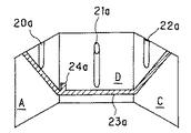
図1は、図14で説明した被写体を、図12で説明した実施形態と同様に、各面の境界で映像が連続するように仮想(入力)カメラ18により撮影し、直方体の各面に貼り付けたものである。この図1によれば、直線が直線画像として表示され、垂直に立設された物体は垂直に立設した物体画像として表示されるため、また、各子画面の表示画像が平面画像として歪みのない画像として表示されるため、直感的に見やすく、しかも、立体的に自車両と障害物等との関係を把握することが可能となる。
【0045】
なお、各面を向いている方向を撮影した映像としては、必ずしも、実際に撮影した映像である必要はなく、例えば、図18の画像合成変換装置3により、広角カメラ2の撮影映像から、特定の面を向いている仮想視点を設定し、この仮想視点に設置したカメラで撮影したかのように変換した映像で良い。また、必ずしも、特定の面を向いた仮想視点を設定する必要はなく、例えば単一の仮想視点と単一の広角カメラを設定し、得られた広角画像から、仮想視点位置からみた特定の面の向きの映像を切り出して表示しても良い。
【0046】
(第4の実施の形態)
次に、本発明の第4の実施形態を説明する。この実施形態では、自車両の後方または前方を表示するに際し、下面に相当する表示領域に、自車両の幅もしくはそれよりもやや広めの映像を表示し、任意の物体が自車両の直進進路上にあるか否かを容易に判断できるようにする。これにより、運転者はこの任意の物体の存在位置を直感的に把握可能となる。以下、図5と図18を用いて第4の実施形態を説明する。
【0047】
図18に示すように、自車両の後方を撮影するようにカメラ2を設置する。図18では、1台のみ描いているが、複数台設置しても良い。これらのカメラによる映像を入力とし、画像合成変換装置3は、図5に示す出力画像を生成する。このとき、図5において、F面には自車両後方の下面方向の映像が表示され、A面には自車両後方の左側面方向の映像が表示され、C面には自車両後方の右側面方向の映像が表示され、B面には自車両後方の映像が表示される。
【0048】
このとき、F面が表示する幅を、自車両の幅、もしくは、自車両の幅よりもやや広めになるように、F面の幅、もしくは、表示する画像を調整する。これにより、F面には、常に、自車両が直進で後退した場合に通過する領域のみが表示されることになる。つまり、F面に写っているものは、自車両の後方に位置し、それ以外、例えばA面に写っているものは、自車両の左後方にあることが一目で理解できる。
【0049】
このように、本発明の第4の実施形態によれば、下面を表示する子画面には、自車両の車幅範囲の映像だけ、あるいはそれより若干広い範囲の映像だけを表示し、自車両の車幅範囲から外れる物体画像は表示しないため、自車両の進行方向にある物体であるか自車両の進行によって接触あるいは衝突する物体であるかの判断が容易となる。
【0050】
【発明の効果】
本発明によれば、車載カメラの撮像画像を容易に立体的に把握でき、直感的に自車両との関係を判断できる映像として表示することが可能となる。
【図面の簡単な説明】
【図1】本発明の一実施形態に係る運転支援表示装置の表示例の模式図
【図2】本発明の第1実施形態に係る運転支援表示装置の表示画面分割方法の説明図
【図3】本発明の第1実施形態に係る運転支援表示装置の表示画面分割方法の説明図
【図4】本発明の第1実施形態に係る運転支援表示装置の表示画面分割例を示す図
【図5】本発明の第1実施形態に係る運転支援表示装置の表示画面分割例の別例を示す図
【図6】本発明の第2実施形態に係る運転支援表示装置の表示画面分割方法の説明図
【図7】本発明の第2実施形態に係る運転支援表示装置の表示画面分割方法の説明図
【図8】本発明の第2実施形態に係る運転支援表示装置の表示画面分割例を示す図
【図9】本発明の第2実施形態に係る運転支援表示装置の表示画面分割例の別例を示す図
【図10】本発明の第3実施形態に係る運転支援表示装置の表示画面分割方法の説明図
【図11】本発明の第3実施形態に係る運転支援表示装置の表示画面分割方法の説明図
【図12】本発明の第3実施形態に係る運転支援表示装置の表示画面分割例を示す図
【図13】本発明の第3実施形態に係る運転支援表示装置の表示画面分割例の別例を示す図
【図14】本発明の一実施形態に係る運転支援表示装置による画面表示と従来の運転支援表示装置による画面表示とを比較する車載カメラの被写体説明図
【図15】従来の運転支援表示装置の表示例を示す図
【図16】従来の運転支援表示装置の表示例を示す図
【図17】従来の運転支援表示装置の表示例を示す図
【図18】従来及び本発明の一実施形態に係る運転支援表示装置の構成図
【図19】従来の運転支援表示装置の表示例を示す図
【符号の説明】
1 車両
2 リアビューカメラ
3 画像合成変換装置(画像処理手段)
4 モニタ
15 直方体(多面体の一例)
16 カメラ
17 モニタ表示画面
18 仮想(入力)カメラ
19 仮想(出力)カメラ
A、C、D、F 子画面領域[0001]
BACKGROUND OF THE INVENTION
The present invention relates to a driving support display device that displays an image of the periphery of a vehicle photographed by an in-vehicle camera on a screen, and in particular, a driving support display device suitable for causing a vehicle periphery image to be perceived three-dimensionally on a two-dimensional display screen. About.
[0002]
[Prior art]
As a device for presenting a video of an in-vehicle camera to a driver for driving support, a rear view system that presents a wide-angle camera image installed behind the vehicle to the driver as it is is common. This rear view system is mainly intended for safety confirmation and parking assistance when the vehicle is moved backward.
[0003]
FIG. 18 is an explanatory diagram of a conventional rear view system. This rear view system is generated by a wide-
[0004]
The wide-
[0005]
In FIG. 18, only one wide-
[0006]
Apart from this, in the prior art described in Japanese Patent Application Laid-Open No. 11-338074, when displaying left and right camera images on a blind corner monitor, the shape of the left and right screens, for example, as shown in FIG. The
[0007]
Further, when the conventional rear view system is used for parking assistance, as shown in the
[0008]
[Problems to be solved by the invention]
In the conventional rear view system described above, a scene as shown in FIG. 14, that is, two parallel
[0009]
Thus, when the captured image of the wide-
[0010]
In other words, the vertical line of the three-dimensional object such as the drum can-
[0011]
In the example of FIG. 15, the drum-
[0012]
In the example shown in FIG. 16, the right angle direction gradually converges as it goes upwards at both ends of the
[0013]
On the other hand, when the left and right independent images are displayed on the same screen, the prior art shown in FIG. 17 allows the right and left cameras to be intuitively understood by setting the left and right screen shapes, and It is possible to display the three-dimensional object in each image without a sense of incongruity. However, the prior art shown in FIG. 17 does not solve the problem of how to display a wide field of view within a single screen like the shooting range of a wide-angle camera.
[0014]
On the
[0015]
An object of the present invention is to provide a driving assistance display device that displays a wide-angle camera image so that the driver can intuitively understand it when displaying it on one screen.
[0016]
[Means for Solving the Problems]
The driving support display device that achieves the above object divides a monitor screen into a plurality of sub-screen regions corresponding to each surface of the polyhedron obtained when the inside of the polyhedron is photographed, and performs image processing on the image captured by the in-vehicle camera And an image processing means for dividing the processed image in correspondence with the small-screen area and displaying each divided image in the corresponding small-screen area.
[0017]
As a result, it is possible to provide a screen configuration that displays video in a direction corresponding to the orientation of each surface, intuitively understand the direction of the video displayed on each sub-screen, and provide an uncomfortable video to the driver. It can be presented.
[0018]
Preferably, in the above, the divided images corresponding to some of the faces of the polyhedron are not displayed on the monitor screen. As a result, unnecessary images can be prevented from being shown to the driver.
[0019]
More preferably, the adjacent sub-screen areas are displayed on the monitor screen while being separated from each other. Alternatively, when displaying the divided images having different display magnifications, the corresponding small-screen area is enlarged and reduced in accordance with the display magnification. As a result, it is possible to present a more easily viewable image to the driver.
[0020]
More preferably, the divided images displayed in the adjacent sub-screen regions are characterized in that images are continuous in the adjacent portions, or the divided images displayed in the adjacent sub-screen regions are The same image overlaps in the adjacent portions. As a result, the relationship between the sub-screens can be easily understood, and even when the object moves across the sub-screens, it can be easily associated and understood.
[0021]
More preferably, a captured image of the vehicle width range of the host vehicle is displayed in a child screen region that displays an image of the lower surface in the traveling direction of the host vehicle, and the captured image outside the vehicle width range is It is characterized by being displayed in an adjacent sub-screen area. Accordingly, it is easy to determine whether the object is in the traveling direction of the host vehicle or the object that contacts or collides with the traveling of the host vehicle.
[0022]
DETAILED DESCRIPTION OF THE INVENTION
Hereinafter, an embodiment of the present invention will be described with reference to the drawings.
[0023]
(First embodiment)
A first embodiment of the present invention will be described with reference to FIGS. The hardware configuration of the driving support display device of the present invention is the same as the configuration shown in FIG. 18, and the wide-angle
[0024]
FIG. 2A shows a state in which the
[0025]
The
[0026]
Therefore, by drawing a line at the boundary of the region so that the shape of each region can be clearly perceived, an image obtained by photographing the left side in region A, an image obtained by photographing the right side in region C, and region D Is an image obtained by imaging the front surface, an image obtained by imaging the upper surface in region E, and an image obtained by imaging the lower side in region F.
[0027]
By doing so, the direction of the area intuitively understood from the shape of the area matches the spatial orientation of the video displayed in the area, and the spatial direction of the video displayed in each area is matched. It is possible to intuitively understand the correct orientation.
[0028]
That is, in this embodiment, the display screen of the monitor is divided into five sub-screens of areas A, C, D, E, and F shown in FIG. 3, and the same orientation as the direction in which each surface of the rectangular parallelepiped faces. Basically, the captured video is divided from wide-angle captured images and pasted to each sub-screen for display.
[0029]
As a configuration of the display screen, it is not always necessary to use all the surfaces. For example, as shown in the
[0030]
In FIG. 5, in addition to the A side, the C side, and the D side, an F side (lower side) is added to form a screen. Further, in order to call the driver's attention in the left and right direction, The child screen is displayed in an enlarged size than other child screens. In FIGS. 4 and 5, the image area itself of each surface of the rectangular parallelepiped is adopted as the shape of the child screen. However, for example, the relative position of each surface such as rounding the corner or curving the boundary line is used. As long as the relationship can be intuitively understood, that is, as long as the direction of each surface can be intuitively understood, the shape of the child screen can be arbitrarily changed.
[0031]
(Second Embodiment)
Next, a second embodiment of the present invention will be described with reference to FIGS. FIG. 6 is a diagram showing a positional relationship between the
[0032]
At this time, the area A in FIG. 7 is the a-plane which is the left side of the
[0033]
In FIG. 6, the b-plane and e-plane of the cuboid 15 are removed, the a-plane and f-plane, and the c-plane and f-plane are separated by boundary lines, respectively, and the a-plane and c-plane are opened to the outside of the cuboid 15 respectively. When the image is taken by the
[0034]
Further, when the
[0035]
For this reason, the image captured by the camera is displayed to the driver by pasting the image captured in each direction on each sub-screen corresponding to each of the areas A, C, D, and F in FIGS. It becomes possible to grasp three-dimensionally.
[0036]
(Third embodiment)
Next, a third embodiment of the present invention will be described with reference to FIGS. 10 to 13 and FIG. In FIG. 10, in this embodiment, a virtual (input)
[0037]
In this example, the subjects to be photographed by the
[0038]
Next, the a-plane image, the d-plane image, and the c-plane image shown in FIG. 11 are pasted inside the a-plane, d-plane, and c-plane of the
[0039]
In FIG. 12, the area A corresponds to the a-plane, the area C corresponds to the c-plane, and the area D corresponds to the d-plane. At this time, from the shape of each region, it is intuitive that the region A displays the image in the left side direction, the region C displays the image in the right side direction, and the region D displays the image in the front direction. Understandable.
[0040]
In FIG. 12, since the video is continuous at the boundary between the surfaces, the positional relationship between the screens is clear, and the whole image can be easily grasped even when the object image exists across the surfaces. In this way, by displaying so as to be continuous at the boundary, even an object that exists across a surface or moves can be easily recognized as one object.
[0041]
FIG. 12 is an example in which images taken by the virtual (input)
[0042]
FIG. 13 shows a configuration in which the areas A, C, and D are separated from each other, and each surface has an overlap area. That is, in the example of FIG. 13, the mark image 24 a exists at the corner of the area A, but this mark image 24 a is also displayed at the corner of the area D adjacent to the area A. As a result, even if each area is separated at the boundary surface, the direction indicated by each area can be intuitively understood from the shape of each area, and each area has an overlap area, so that each area Can be easily understood.
[0043]
As described above, by providing the overlap region, it is possible to easily associate even when the enlargement ratios of the respective surfaces are different. Further, even if a part of the object is hidden at the boundary of a certain surface, at least more of the object is reflected on the other surface, so that there is an effect that the association is easy and easy to recognize.
[0044]
In FIG. 1, the subject described in FIG. 14 is photographed by the virtual (input)
[0045]
Note that the video shot in the direction facing each surface does not necessarily have to be actually shot. For example, the image synthesized
[0046]
(Fourth embodiment)
Next, a fourth embodiment of the present invention will be described. In this embodiment, when displaying the rear or front of the host vehicle, an image of the width of the host vehicle or slightly wider than that is displayed in a display area corresponding to the lower surface, and an arbitrary object is displayed on the straight path of the host vehicle. So that it can be easily determined whether or not As a result, the driver can intuitively grasp the location of the arbitrary object. Hereinafter, the fourth embodiment will be described with reference to FIGS. 5 and 18.
[0047]
As shown in FIG. 18, the
[0048]
At this time, the width of the F surface or the image to be displayed is adjusted so that the width displayed on the F surface is slightly wider than the width of the own vehicle or the width of the own vehicle. Thereby, only the area | region which passes when the own vehicle reverse | retreats straight ahead is always displayed on the F surface. That is, it can be understood at a glance that what is reflected in the F-plane is located behind the host vehicle, and, for example, what is reflected in the A-plane is located on the left rear side of the host vehicle.
[0049]
As described above, according to the fourth embodiment of the present invention, only the image of the vehicle width range of the host vehicle or only the image of a slightly wider range is displayed on the sub-screen displaying the lower surface. Since an object image outside the vehicle width range is not displayed, it is easy to determine whether the object is in the traveling direction of the host vehicle or an object that contacts or collides with the traveling of the host vehicle.
[0050]
【The invention's effect】
According to the present invention, a captured image of an in-vehicle camera can be easily grasped in a three-dimensional manner, and can be displayed as an image from which a relationship with the host vehicle can be intuitively determined.
[Brief description of the drawings]
FIG. 1 is a schematic diagram of a display example of a driving assistance display device according to an embodiment of the present invention. FIG. 2 is an explanatory diagram of a display screen dividing method of the driving assistance display device according to the first embodiment of the present invention. FIG. 4 is an explanatory view of a display screen dividing method of the driving assistance display device according to the first embodiment of the present invention. FIG. 4 is a diagram showing an example of dividing the display screen of the driving assistance display device according to the first embodiment of the present invention. FIG. 6 is a diagram showing another example of the display screen division example of the driving assistance display device according to the first embodiment of the present invention. FIG. 6 is an explanatory diagram of the display screen dividing method of the driving assistance display device according to the second embodiment of the present invention. FIG. 7 is an explanatory diagram of a display screen dividing method of the driving support display device according to the second embodiment of the present invention. FIG. 8 is a diagram showing an example of display screen division of the driving support display device according to the second embodiment of the present invention. FIG. 9 shows another display screen division example of the driving support display device according to the second embodiment of the present invention. FIG. 10 is an explanatory diagram of a display screen dividing method of the driving support display device according to the third embodiment of the present invention. FIG. 11 is a display screen dividing method of the driving support display device according to the third embodiment of the present invention. FIG. 12 is a diagram showing a display screen division example of the driving support display device according to the third embodiment of the present invention. FIG. 13 is a display screen division example of the driving support display device according to the third embodiment of the present invention. FIG. 14 is a diagram illustrating a subject of an in-vehicle camera that compares a screen display by a driving support display device according to an embodiment of the present invention with a screen display by a conventional driving support display device. FIG. 16 is a diagram showing a display example of a conventional driving support display device. FIG. 17 is a diagram showing a display example of a conventional driving support display device. FIG. A driving assistance display device according to an embodiment of the invention Figure [EXPLANATION OF SYMBOLS] showing a display example of a deposition diagram 19 conventional drive assist display device
DESCRIPTION OF SYMBOLS 1
4 monitor 15 cuboid (an example of polyhedron)
16
Claims (7)
前記車両周辺を撮影する撮像装置から出力される映像を変換する画像合成変換装置と、
前記画像合成変換装置の出力を表示する表示装置とから構成される運転支援表示装置であって、
前記画像合成変換装置は、
仮想的な撮像装置により任意の多面体を撮影した場合に、
前記多面体を構成する各平面から任意の複数個の平面を選択して、前記選択された平面毎に対応する子画面を生成し、
前記子画面を前記多面体を構成する各平面が前記仮想的な撮像装置上に映し出されるのと同じ位置関係で出力画像上に配置し、
生成された前記子画面は、
前記仮想的な撮像装置上に映し出される前記多面体を構成するそれぞれの子画面に対応する平面と同じ形状であり、
前記子画面にはそれぞれの子画面が対応する前記多面体を構成する平面が指し示す方向の前記車両周辺を撮影する撮像装置で撮影した映像の一部が表示されることを特徴とする運転支援表示装置。 An imaging device for photographing the periphery of the vehicle;
An image synthesis conversion device for converting video output from an imaging device for photographing the periphery of the vehicle;
A driving support display device comprising a display device for displaying the output of the image composition conversion device,
The image composition conversion device includes:
When shooting an arbitrary polyhedron with a virtual imaging device,
Selecting an arbitrary plurality of planes from each plane constituting the polyhedron, and generating a sub-screen corresponding to each of the selected planes;
The sub-screen is arranged on the output image in the same positional relationship as each plane constituting the polyhedron is projected on the virtual imaging device,
The generated child screen is
The same shape as the plane corresponding to each sub-screen constituting the polyhedron projected on the virtual imaging device;
A driving assistance display device characterized in that a part of a video imaged by an imaging device that images the periphery of the vehicle in a direction indicated by a plane constituting the polyhedron to which each of the child screens corresponds is displayed on the child screen. .
Priority Applications (4)
| Application Number | Priority Date | Filing Date | Title |
|---|---|---|---|
| JP2001242410A JP4786076B2 (en) | 2001-08-09 | 2001-08-09 | Driving support display device |
| DE60219730T DE60219730T2 (en) | 2001-08-09 | 2002-08-09 | Display device for driving assistance |
| EP02017755A EP1288618B1 (en) | 2001-08-09 | 2002-08-09 | Driving assistance display apparatus |
| US10/215,439 US6801127B2 (en) | 2001-08-09 | 2002-08-09 | Driving assistance display apparatus |
Applications Claiming Priority (1)
| Application Number | Priority Date | Filing Date | Title |
|---|---|---|---|
| JP2001242410A JP4786076B2 (en) | 2001-08-09 | 2001-08-09 | Driving support display device |
Publications (2)
| Publication Number | Publication Date |
|---|---|
| JP2003061084A JP2003061084A (en) | 2003-02-28 |
| JP4786076B2 true JP4786076B2 (en) | 2011-10-05 |
Family
ID=19072684
Family Applications (1)
| Application Number | Title | Priority Date | Filing Date |
|---|---|---|---|
| JP2001242410A Expired - Lifetime JP4786076B2 (en) | 2001-08-09 | 2001-08-09 | Driving support display device |
Country Status (4)
| Country | Link |
|---|---|
| US (1) | US6801127B2 (en) |
| EP (1) | EP1288618B1 (en) |
| JP (1) | JP4786076B2 (en) |
| DE (1) | DE60219730T2 (en) |
Families Citing this family (100)
| Publication number | Priority date | Publication date | Assignee | Title |
|---|---|---|---|---|
| US5877897A (en) | 1993-02-26 | 1999-03-02 | Donnelly Corporation | Automatic rearview mirror, vehicle lighting control and vehicle interior monitoring system using a photosensor array |
| US6822563B2 (en) | 1997-09-22 | 2004-11-23 | Donnelly Corporation | Vehicle imaging system with accessory control |
| US5910854A (en) | 1993-02-26 | 1999-06-08 | Donnelly Corporation | Electrochromic polymeric solid films, manufacturing electrochromic devices using such solid films, and processes for making such solid films and devices |
| US5668663A (en) | 1994-05-05 | 1997-09-16 | Donnelly Corporation | Electrochromic mirrors and devices |
| US6891563B2 (en) | 1996-05-22 | 2005-05-10 | Donnelly Corporation | Vehicular vision system |
| US7655894B2 (en) | 1996-03-25 | 2010-02-02 | Donnelly Corporation | Vehicular image sensing system |
| US6172613B1 (en) * | 1998-02-18 | 2001-01-09 | Donnelly Corporation | Rearview mirror assembly incorporating vehicle information display |
| US8294975B2 (en) | 1997-08-25 | 2012-10-23 | Donnelly Corporation | Automotive rearview mirror assembly |
| US6124886A (en) | 1997-08-25 | 2000-09-26 | Donnelly Corporation | Modular rearview mirror assembly |
| US6326613B1 (en) | 1998-01-07 | 2001-12-04 | Donnelly Corporation | Vehicle interior mirror assembly adapted for containing a rain sensor |
| US6445287B1 (en) | 2000-02-28 | 2002-09-03 | Donnelly Corporation | Tire inflation assistance monitoring system |
| US8288711B2 (en) | 1998-01-07 | 2012-10-16 | Donnelly Corporation | Interior rearview mirror system with forwardly-viewing camera and a control |
| US6477464B2 (en) | 2000-03-09 | 2002-11-05 | Donnelly Corporation | Complete mirror-based global-positioning system (GPS) navigation solution |
| US6329925B1 (en) | 1999-11-24 | 2001-12-11 | Donnelly Corporation | Rearview mirror assembly with added feature modular display |
| US6693517B2 (en) | 2000-04-21 | 2004-02-17 | Donnelly Corporation | Vehicle mirror assembly communicating wirelessly with vehicle accessories and occupants |
| WO2007053710A2 (en) | 2005-11-01 | 2007-05-10 | Donnelly Corporation | Interior rearview mirror with display |
| US7167796B2 (en) | 2000-03-09 | 2007-01-23 | Donnelly Corporation | Vehicle navigation system for use with a telematics system |
| US7370983B2 (en) | 2000-03-02 | 2008-05-13 | Donnelly Corporation | Interior mirror assembly with display |
| AU2001243285A1 (en) * | 2000-03-02 | 2001-09-12 | Donnelly Corporation | Video mirror systems incorporating an accessory module |
| US7581859B2 (en) | 2005-09-14 | 2009-09-01 | Donnelly Corp. | Display device for exterior rearview mirror |
| ES2287266T3 (en) | 2001-01-23 | 2007-12-16 | Donnelly Corporation | IMPROVED VEHICLE LIGHTING SYSTEM. |
| US7255451B2 (en) | 2002-09-20 | 2007-08-14 | Donnelly Corporation | Electro-optic mirror cell |
| JP2003104145A (en) * | 2001-09-28 | 2003-04-09 | Matsushita Electric Ind Co Ltd | Operation support display device |
| US6918674B2 (en) | 2002-05-03 | 2005-07-19 | Donnelly Corporation | Vehicle rearview mirror system |
| EP1504276B1 (en) | 2002-05-03 | 2012-08-08 | Donnelly Corporation | Object detection system for vehicle |
| US7329013B2 (en) | 2002-06-06 | 2008-02-12 | Donnelly Corporation | Interior rearview mirror system with compass |
| WO2003105099A1 (en) | 2002-06-06 | 2003-12-18 | Donnelly Corporation | Interior rearview mirror system with compass |
| US7310177B2 (en) | 2002-09-20 | 2007-12-18 | Donnelly Corporation | Electro-optic reflective element assembly |
| AU2003278863A1 (en) | 2002-09-20 | 2004-04-08 | Donnelly Corporation | Mirror reflective element assembly |
| WO2004103772A2 (en) | 2003-05-19 | 2004-12-02 | Donnelly Corporation | Mirror assembly for vehicle |
| US7446924B2 (en) | 2003-10-02 | 2008-11-04 | Donnelly Corporation | Mirror reflective element assembly including electronic component |
| US7308341B2 (en) | 2003-10-14 | 2007-12-11 | Donnelly Corporation | Vehicle communication system |
| US7526103B2 (en) | 2004-04-15 | 2009-04-28 | Donnelly Corporation | Imaging system for vehicle |
| US7881496B2 (en) | 2004-09-30 | 2011-02-01 | Donnelly Corporation | Vision system for vehicle |
| US20060161713A1 (en) * | 2005-01-20 | 2006-07-20 | Belady Christian L | Mounting a computer in a transport vehicle |
| EP1883855B1 (en) | 2005-05-16 | 2011-07-20 | Donnelly Corporation | Vehicle mirror assembly with indicia at reflective element |
| JP4679293B2 (en) * | 2005-08-08 | 2011-04-27 | 三洋電機株式会社 | In-vehicle panoramic camera system |
| FR2891934B1 (en) * | 2005-10-12 | 2008-01-18 | Valeo Electronique Sys Liaison | DEVICE FOR PROCESSING VIDEO DATA FOR A MOTOR VEHICLE |
| MX2008011219A (en) | 2006-03-09 | 2008-09-11 | Gentex Corp | Vehicle rearview assembly including a high intensity display. |
| US7972045B2 (en) | 2006-08-11 | 2011-07-05 | Donnelly Corporation | Automatic headlamp control system |
| JP4258539B2 (en) | 2006-08-31 | 2009-04-30 | 株式会社日立製作所 | Multiple angle of view camera |
| JP5044204B2 (en) * | 2006-12-18 | 2012-10-10 | クラリオン株式会社 | Driving assistance device |
| CN101179409B (en) * | 2006-12-30 | 2013-08-14 | 腾讯科技(深圳)有限公司 | Method and apparatus for displaying multi-party video in instant communication |
| JP4793307B2 (en) * | 2007-04-03 | 2011-10-12 | 株式会社デンソー | Vehicle periphery monitoring device |
| US8594387B2 (en) * | 2007-04-23 | 2013-11-26 | Intel-Ge Care Innovations Llc | Text capture and presentation device |
| US8694195B2 (en) | 2007-12-04 | 2014-04-08 | Volkswagen Ag | Motor vehicle having a wheel-view camera and method for controlling a wheel-view camera system |
| JP2009225322A (en) * | 2008-03-18 | 2009-10-01 | Hyundai Motor Co Ltd | Vehicle information display system |
| JP5222597B2 (en) * | 2008-03-19 | 2013-06-26 | 三洋電機株式会社 | Image processing apparatus and method, driving support system, and vehicle |
| US8154418B2 (en) | 2008-03-31 | 2012-04-10 | Magna Mirrors Of America, Inc. | Interior rearview mirror system |
| US8582052B2 (en) * | 2008-08-22 | 2013-11-12 | Gentex Corporation | Discrete LED backlight control for a reduced power LCD display system |
| US9487144B2 (en) | 2008-10-16 | 2016-11-08 | Magna Mirrors Of America, Inc. | Interior mirror assembly with display |
| JP2010109483A (en) * | 2008-10-28 | 2010-05-13 | Honda Motor Co Ltd | Vehicle-surroundings displaying method |
| US8044781B2 (en) * | 2008-11-10 | 2011-10-25 | Volkswagen Ag | System and method for displaying a 3D vehicle surrounding with adjustable point of view including a distance sensor |
| JP5102795B2 (en) * | 2009-03-13 | 2012-12-19 | パナソニック株式会社 | Driving support display device |
| JP5407516B2 (en) | 2009-04-21 | 2014-02-05 | 日産自動車株式会社 | Vehicle display device |
| US20100313150A1 (en) * | 2009-06-03 | 2010-12-09 | Microsoft Corporation | Separable displays and composable surfaces |
| JP5598731B2 (en) * | 2009-09-11 | 2014-10-01 | アイシン精機株式会社 | Vehicle periphery monitoring device |
| JP5451497B2 (en) * | 2010-04-08 | 2014-03-26 | パナソニック株式会社 | Driving support display device |
| JP5672862B2 (en) * | 2010-08-27 | 2015-02-18 | ソニー株式会社 | Imaging apparatus, imaging system, and imaging method |
| JP2012156797A (en) * | 2011-01-26 | 2012-08-16 | Sony Corp | Image processing apparatus and image processing method |
| WO2013014872A1 (en) * | 2011-07-25 | 2013-01-31 | パナソニック株式会社 | Image conversion device, camera, video system, image conversion method and recording medium recording a program |
| EP2763405B1 (en) * | 2011-09-29 | 2017-06-28 | Toyota Jidosha Kabushiki Kaisha | Image display device and image display method |
| DE102011121616A1 (en) * | 2011-12-20 | 2013-06-20 | Audi Ag | Method for controlling a display device of a motor vehicle |
| US10457209B2 (en) | 2012-02-22 | 2019-10-29 | Magna Electronics Inc. | Vehicle vision system with multi-paned view |
| US9319637B2 (en) | 2012-03-27 | 2016-04-19 | Magna Electronics Inc. | Vehicle vision system with lens pollution detection |
| US8879139B2 (en) | 2012-04-24 | 2014-11-04 | Gentex Corporation | Display mirror assembly |
| WO2014002708A1 (en) * | 2012-06-27 | 2014-01-03 | 日本精機株式会社 | Information providing device for vehicle |
| US9242602B2 (en) * | 2012-08-27 | 2016-01-26 | Fotonation Limited | Rearview imaging systems for vehicle |
| US9707896B2 (en) | 2012-10-15 | 2017-07-18 | Magna Electronics Inc. | Vehicle camera lens dirt protection via air flow |
| US9445057B2 (en) | 2013-02-20 | 2016-09-13 | Magna Electronics Inc. | Vehicle vision system with dirt detection |
| US9598018B2 (en) | 2013-03-15 | 2017-03-21 | Gentex Corporation | Display mirror assembly |
| US9575315B2 (en) | 2013-09-24 | 2017-02-21 | Gentex Corporation | Display mirror assembly |
| TWI533694B (en) * | 2013-12-18 | 2016-05-11 | 歐特明電子股份有限公司 | Obstacle detection and display system for vehicle |
| US9511715B2 (en) | 2014-01-31 | 2016-12-06 | Gentex Corporation | Backlighting assembly for display for reducing cross-hatching |
| EP3119643B1 (en) | 2014-03-21 | 2018-05-23 | Gentex Corporation | Tri-modal display mirror assembly |
| CN106163873B (en) | 2014-04-01 | 2019-04-26 | 金泰克斯公司 | Automatic display mirror assembly |
| US9694751B2 (en) | 2014-09-19 | 2017-07-04 | Gentex Corporation | Rearview assembly |
| US9694752B2 (en) | 2014-11-07 | 2017-07-04 | Gentex Corporation | Full display mirror actuator |
| US10071689B2 (en) | 2014-11-13 | 2018-09-11 | Gentex Corporation | Rearview mirror system with a display |
| KR101997815B1 (en) | 2014-12-03 | 2019-07-08 | 젠텍스 코포레이션 | Display mirror assembly |
| USD746744S1 (en) | 2014-12-05 | 2016-01-05 | Gentex Corporation | Rearview device |
| US9744907B2 (en) | 2014-12-29 | 2017-08-29 | Gentex Corporation | Vehicle vision system having adjustable displayed field of view |
| US9720278B2 (en) | 2015-01-22 | 2017-08-01 | Gentex Corporation | Low cost optical film stack |
| EP3286038A4 (en) | 2015-04-20 | 2018-04-25 | Gentex Corporation | Rearview assembly with applique |
| CN107614324B (en) | 2015-05-18 | 2020-11-27 | 金泰克斯公司 | Complete display rearview device |
| EP3310618A4 (en) | 2015-06-22 | 2018-07-04 | Gentex Corporation | System and method for processing streamed video images to correct for flicker of amplitude-modulated lights |
| CN108349436B (en) | 2015-10-30 | 2019-12-20 | 金泰克斯公司 | Rear-view device |
| USD798207S1 (en) | 2015-10-30 | 2017-09-26 | Gentex Corporation | Rearview mirror assembly |
| WO2017075420A1 (en) | 2015-10-30 | 2017-05-04 | Gentex Corporation | Toggle paddle |
| USD797627S1 (en) | 2015-10-30 | 2017-09-19 | Gentex Corporation | Rearview mirror device |
| USD800618S1 (en) | 2015-11-02 | 2017-10-24 | Gentex Corporation | Toggle paddle for a rear view device |
| USD845851S1 (en) | 2016-03-31 | 2019-04-16 | Gentex Corporation | Rearview device |
| USD817238S1 (en) | 2016-04-29 | 2018-05-08 | Gentex Corporation | Rearview device |
| US10025138B2 (en) | 2016-06-06 | 2018-07-17 | Gentex Corporation | Illuminating display with light gathering structure |
| EP3264368A1 (en) | 2016-06-28 | 2018-01-03 | Nokia Technologies Oy | Display of polyhedral virtual objects |
| USD809984S1 (en) | 2016-12-07 | 2018-02-13 | Gentex Corporation | Rearview assembly |
| USD854473S1 (en) | 2016-12-16 | 2019-07-23 | Gentex Corporation | Rearview assembly |
| US20180191966A1 (en) | 2016-12-30 | 2018-07-05 | Gentex Corporation | Full display mirror with on-demand spotter view |
| US10735638B2 (en) | 2017-03-17 | 2020-08-04 | Gentex Corporation | Dual display reverse camera system |
| JP6665819B2 (en) * | 2017-03-17 | 2020-03-13 | トヨタ自動車株式会社 | In-vehicle display device |
Family Cites Families (18)
| Publication number | Priority date | Publication date | Assignee | Title |
|---|---|---|---|---|
| JPH07367Y2 (en) * | 1988-12-08 | 1995-01-11 | 三菱自動車工業株式会社 | Vehicle visibility device |
| JPH05143894A (en) * | 1991-11-15 | 1993-06-11 | Daihatsu Motor Co Ltd | Control method for monitor for automobile |
| JPH06227318A (en) * | 1993-02-08 | 1994-08-16 | Hitachi Ltd | Rearview monitoring device of vehicle and method thereof |
| US5289321A (en) * | 1993-02-12 | 1994-02-22 | Secor James O | Consolidated rear view camera and display system for motor vehicle |
| US5670935A (en) * | 1993-02-26 | 1997-09-23 | Donnelly Corporation | Rearview vision system for vehicle including panoramic view |
| DE69434851T2 (en) | 1993-08-12 | 2007-04-19 | Seiko Epson Corp. | Head-mounted image display device and data processing device containing the same |
| US6331869B1 (en) | 1998-08-07 | 2001-12-18 | Be Here Corporation | Method and apparatus for electronically distributing motion panoramic images |
| JPH10145777A (en) * | 1996-11-05 | 1998-05-29 | Hitachi Denshi Ltd | Camera image display device for mobile object |
| US6188939B1 (en) * | 1997-08-18 | 2001-02-13 | The Texas A&M University System | Advanced law enforcement and response technology |
| JP3511892B2 (en) * | 1998-05-25 | 2004-03-29 | 日産自動車株式会社 | Ambient monitoring device for vehicles |
| EP2309453A3 (en) * | 1998-07-31 | 2012-09-26 | Panasonic Corporation | Image displaying apparatus and image displaying method |
| JP4200343B2 (en) * | 1999-02-19 | 2008-12-24 | ソニー株式会社 | Monitor device |
| AU4336400A (en) * | 1999-04-08 | 2000-10-23 | Internet Pictures Corporation | Method and apparatus for providing virtual processing effects for wide-angle video images |
| CA2369648A1 (en) * | 1999-04-16 | 2000-10-26 | Matsushita Electric Industrial Co., Limited | Image processing device and monitoring system |
| JP4238429B2 (en) * | 1999-09-14 | 2009-03-18 | 住友電気工業株式会社 | Travel support device for moving body |
| JP2001242410A (en) * | 2000-02-29 | 2001-09-07 | Toppan Forms Co Ltd | Perforation forming device and forming method |
| JP3627914B2 (en) * | 2000-05-23 | 2005-03-09 | シャープ株式会社 | Vehicle perimeter monitoring system |
| JP4860835B2 (en) * | 2001-06-11 | 2012-01-25 | クラリオン株式会社 | Panorama image display method and panorama image display apparatus |
-
2001
- 2001-08-09 JP JP2001242410A patent/JP4786076B2/en not_active Expired - Lifetime
-
2002
- 2002-08-09 EP EP02017755A patent/EP1288618B1/en not_active Expired - Lifetime
- 2002-08-09 DE DE60219730T patent/DE60219730T2/en not_active Expired - Lifetime
- 2002-08-09 US US10/215,439 patent/US6801127B2/en not_active Expired - Lifetime
Also Published As
| Publication number | Publication date |
|---|---|
| EP1288618B1 (en) | 2007-04-25 |
| EP1288618A2 (en) | 2003-03-05 |
| US6801127B2 (en) | 2004-10-05 |
| DE60219730T2 (en) | 2008-01-17 |
| US20030035050A1 (en) | 2003-02-20 |
| JP2003061084A (en) | 2003-02-28 |
| EP1288618A3 (en) | 2003-12-10 |
| DE60219730D1 (en) | 2007-06-06 |
Similar Documents
| Publication | Publication Date | Title |
|---|---|---|
| JP4786076B2 (en) | Driving support display device | |
| JP3871614B2 (en) | Driving assistance device | |
| JP4596978B2 (en) | Driving support system | |
| JP5194679B2 (en) | Vehicle periphery monitoring device and video display method | |
| JP4934308B2 (en) | Driving support system | |
| JP5320970B2 (en) | Vehicle display device and display method | |
| JP4762698B2 (en) | Vehicle peripheral image display device | |
| JP5682788B2 (en) | Vehicle periphery monitoring device | |
| JP4512293B2 (en) | Monitoring system and monitoring method | |
| JP5321711B2 (en) | Vehicle periphery monitoring device and video display method | |
| JP4248570B2 (en) | Image processing apparatus and visibility support apparatus and method | |
| WO2012096058A1 (en) | Image generating device | |
| JP5209578B2 (en) | Image display device for vehicle | |
| JP4315968B2 (en) | Image processing apparatus and visibility support apparatus and method | |
| WO2003075573A1 (en) | Image display controller | |
| JP3753681B2 (en) | Monitoring system | |
| JP3834967B2 (en) | Blind spot range display device | |
| JP4682664B2 (en) | Perimeter monitoring system | |
| WO2005102777A1 (en) | Image display device for mounting on vehicle | |
| JP5226621B2 (en) | Image display device for vehicle | |
| JP4706896B2 (en) | Wide-angle image correction method and vehicle periphery monitoring system | |
| JP2004235986A (en) | Monitoring system | |
| WO2021192508A1 (en) | Image composing device and image composing method | |
| US20220222947A1 (en) | Method for generating an image of vehicle surroundings, and apparatus for generating an image of vehicle surroundings | |
| JP2005045338A (en) | In-vehicle monitor system for three-dimensional display |
Legal Events
| Date | Code | Title | Description |
|---|---|---|---|
| RD04 | Notification of resignation of power of attorney |
Free format text: JAPANESE INTERMEDIATE CODE: A7424 Effective date: 20060324 |
|
| RD02 | Notification of acceptance of power of attorney |
Free format text: JAPANESE INTERMEDIATE CODE: A7422 Effective date: 20071114 |
|
| RD04 | Notification of resignation of power of attorney |
Free format text: JAPANESE INTERMEDIATE CODE: A7424 Effective date: 20071121 |
|
| RD02 | Notification of acceptance of power of attorney |
Free format text: JAPANESE INTERMEDIATE CODE: A7422 Effective date: 20071128 |
|
| RD04 | Notification of resignation of power of attorney |
Free format text: JAPANESE INTERMEDIATE CODE: A7424 Effective date: 20071205 |
|
| RD04 | Notification of resignation of power of attorney |
Free format text: JAPANESE INTERMEDIATE CODE: A7424 Effective date: 20071212 |
|
| A621 | Written request for application examination |
Free format text: JAPANESE INTERMEDIATE CODE: A621 Effective date: 20080702 |
|
| A977 | Report on retrieval |
Free format text: JAPANESE INTERMEDIATE CODE: A971007 Effective date: 20101022 |
|
| A131 | Notification of reasons for refusal |
Free format text: JAPANESE INTERMEDIATE CODE: A131 Effective date: 20101102 |
|
| A521 | Request for written amendment filed |
Free format text: JAPANESE INTERMEDIATE CODE: A523 Effective date: 20101207 |
|
| TRDD | Decision of grant or rejection written | ||
| A01 | Written decision to grant a patent or to grant a registration (utility model) |
Free format text: JAPANESE INTERMEDIATE CODE: A01 Effective date: 20110614 |
|
| A01 | Written decision to grant a patent or to grant a registration (utility model) |
Free format text: JAPANESE INTERMEDIATE CODE: A01 |
|
| A61 | First payment of annual fees (during grant procedure) |
Free format text: JAPANESE INTERMEDIATE CODE: A61 Effective date: 20110713 |
|
| R150 | Certificate of patent or registration of utility model |
Ref document number: 4786076 Country of ref document: JP Free format text: JAPANESE INTERMEDIATE CODE: R150 Free format text: JAPANESE INTERMEDIATE CODE: R150 |
|
| FPAY | Renewal fee payment (event date is renewal date of database) |
Free format text: PAYMENT UNTIL: 20140722 Year of fee payment: 3 |
|
| EXPY | Cancellation because of completion of term |