JP4784805B2 - Coin hopper rotating disk - Google Patents
Coin hopper rotating disk Download PDFInfo
- Publication number
- JP4784805B2 JP4784805B2 JP2004107051A JP2004107051A JP4784805B2 JP 4784805 B2 JP4784805 B2 JP 4784805B2 JP 2004107051 A JP2004107051 A JP 2004107051A JP 2004107051 A JP2004107051 A JP 2004107051A JP 4784805 B2 JP4784805 B2 JP 4784805B2
- Authority
- JP
- Japan
- Prior art keywords
- coin
- rotating disk
- roller
- pushing
- pushing portion
- Prior art date
- Legal status (The legal status is an assumption and is not a legal conclusion. Google has not performed a legal analysis and makes no representation as to the accuracy of the status listed.)
- Expired - Fee Related
Links
Images


Classifications
-
- G—PHYSICS
- G07—CHECKING-DEVICES
- G07D—HANDLING OF COINS OR VALUABLE PAPERS, e.g. TESTING, SORTING BY DENOMINATIONS, COUNTING, DISPENSING, CHANGING OR DEPOSITING
- G07D9/00—Counting coins; Handling of coins not provided for in the other groups of this subclass
- G07D9/008—Feeding coins from bulk
Landscapes
- Physics & Mathematics (AREA)
- General Physics & Mathematics (AREA)
- Slot Machines And Peripheral Devices (AREA)
- Control Of Vending Devices And Auxiliary Devices For Vending Devices (AREA)
Description
本発明は、コインホッパに用いる回転ディスクに設けたコインを出口から押し出す押進部の改良に関する。
詳しくは、耐久性を高めた押進部を有する回転ディスクに関する。
さらに詳しくは、押進部をローラで構成した回転ディスクに関する。
なお、本明細書で使用する「コイン」は、通貨であるコイン、ゲーム機等に使われるトークン等を包含する。
The present invention relates to an improvement of a pushing portion that pushes out coins provided on a rotary disk used in a coin hopper from an outlet.
Specifically, the present invention relates to a rotating disk having a pushing portion with improved durability.
More specifically, the present invention relates to a rotating disk having a pushing portion constituted by a roller.
Note that “coin” used in this specification includes a coin used as a currency, a token used for a game machine, and the like.
回転ディスクから一個ずつ送り出されたコインを回転するスクレーパによって垂直上方に伸びるエスカレータによって上方に案内する装置が第1の従来技術として知られている(例えば、特許文献1参照。)。
一方、コインが回転ディスクの押進部によって押し進められ、その回転ディスクの下方のコインの進行経路に配置したコインガイドによってその回転ディスクの周方向に案内され、コインを一枚ずつ払い出すコインホッパが第2の従来技術として知られている。
通常この押進部は回転ディスクと一体に樹脂で成形される。
樹脂成形された押進部は、コインとの摺接による摩耗を防止するため、最も摩耗する部位に固定金属ピンを配置している(例えば、特許文献2参照。)。
また、押進部を有する回転ディスクを金属で製造することも知られている。
A device that guides coins fed one by one from a rotating disk upward by an escalator that extends vertically upward by a rotating scraper is known as a first prior art (see, for example, Patent Document 1).
On the other hand, a coin hopper is pushed forward by the pushing portion of the rotating disk and guided in the circumferential direction of the rotating disk by a coin guide arranged on the coin traveling path below the rotating disk, and a coin hopper for paying out coins one by one is 2 is known as the prior art.
Usually, this pushing portion is molded of resin integrally with the rotating disk.
In the resin-molded pushing portion, a fixed metal pin is disposed at the most worn portion in order to prevent wear due to sliding contact with a coin (see, for example, Patent Document 2).
It is also known to manufacture a rotating disk having a pushing portion with metal.
第1の従来技術において、装置を小型化するためスクレーパを使わずにコインを区分けして送り出す回転ディスクの押進部によって直接エスカレータに送り出すことが試みられている。
この場合、エスカレータは湾曲部及びほぼ垂直に伸びる部位を有するため、湾曲部によるコインの進行抵抗及びコインの重量が押進部に加わる。
そのため、押進部とコインとの接触圧力が高まり、鉄系焼結品の回転ディスクを使用しても摩耗するという問題がある。
押進部が摩耗した場合、押進部によるコインの押進方向が変化するため、コインの送り出しが好適に行われないという問題がある。
この解決のため、特許文献2に開示されるように、押進部の摩耗する部位に耐摩耗性を有する別部材を配置することができる。
しかし、この構造においても、コインと押進部との摺接関係は変わらないため、長寿命化のメリットはあるが、摩耗を解消することはできない。
In the first prior art, an attempt has been made to directly send the coins to the escalator by a pushing portion of a rotating disk which sorts and sends coins without using a scraper in order to reduce the size of the apparatus.
In this case, since the escalator has a curved portion and a part extending substantially vertically, the resistance of the coin due to the curved portion and the weight of the coin are added to the pushing portion.
For this reason, the contact pressure between the pushing portion and the coin is increased, and there is a problem that even if a rotating disk of an iron-based sintered product is used, it is worn.
When the pushing part is worn, the pushing direction of the coin by the pushing part is changed, so that there is a problem that the coin is not suitably fed out.
In order to solve this problem, as disclosed in Patent Document 2, a separate member having wear resistance can be disposed at a portion where the pushing portion is worn.
However, even in this structure, since the sliding contact relationship between the coin and the pushing portion does not change, there is an advantage in extending the life, but the wear cannot be eliminated.
本発明の第1の目的は、回転ディスクに一体的に設けられ、かつ、コインを送り出す押進部の摩耗を実質的に防止することである。
本発明の第2の目的は、樹脂製回転ディスクに適した実質的に摩耗しない押進部を提供することである。
A first object of the present invention is to substantially prevent wear of a pushing portion that is provided integrally with a rotating disk and feeds coins.
A second object of the present invention is to provide a pushing portion which is suitable for a resin-made rotating disk and does not wear substantially.
この目的を達成するため、請求項1の発明にかかるコインホッパの回転ディスクは次のように構成されている。
コインの保留ボウル、前記保留ボウルの底部に位置しコインを押す押進部を有する回転ディスクを有するコインホッパにおいて、前記押進部は、前記回転ディスクの回転軸心に対し平行に前記回転ディスクに固定された大径頭部を有するブッシュ、及び、その大径頭部に回転自在に嵌めあわされたリング状のローラを含む押進ローラであるコインホッパの回転ディスクである。
In order to achieve this object, the rotating disk of the coin hopper according to the first aspect of the present invention is configured as follows.
In a coin hopper having a coin holding bowl and a rotating disk having a pushing part located at the bottom of the holding bowl and pushing a coin, the pushing part is fixed to the rotating disk in parallel to the rotation axis of the rotating disk. A rotating disk for a coin hopper which is a push roller including a bush having a large diameter head and a ring-shaped roller rotatably fitted to the large diameter head .
この構成において、コインは押進部である押進ローラによって、押し出される。
すなわち、コインと押進部との間の摩擦力よりも押進ローラの軸受部の摩擦力の方が小さいため、コインの移動につれて押進ローラが回る。
これにより、コインと押進部とは実質的に滑り接触しない。
したがって、押進ローラ、換言すれば、押進部は実質的に摩耗しないという効果がある。
In this configuration, the coin is pushed out by a pushing roller which is a pushing portion.
That is, since the frictional force of the bearing portion of the pushing roller is smaller than the frictional force between the coin and the pushing portion, the pushing roller rotates as the coin moves.
Thereby, the coin and the pushing portion are not substantially in sliding contact.
Therefore, there is an effect that the pushing roller, in other words, the pushing portion is not substantially worn.
さらに、前記押進ローラは、前記回転ディスクの回転軸心に対し平行に前記回転ディスクに固定され、かつ、大径頭部を有するブッシュ、その大径頭部に回転自在に嵌めあわされたリング状のローラを含んでいる。
この構成において、ローラはブッシュの大径頭部によって回転自在に支持されている。
この大径頭部は、ローラのストッパと軸受を兼用しており、ローラは大径頭部の周面によって面で回転自在に支持されている。
換言すれば、大径頭部によってローラを所定位置に保持するため、回転ディスクの裏面とスライドベースとの間という、実質コイン厚み以下の厚みでローラを回転自在に支持することが可能である。
さらに、コインからローラに加わる力は大径頭部の周面によって分散して受けられるから、単位面積当たりの接触圧が低下するため、それらの間の摩耗は実質的に発生しないという効果がある。
Further , the push roller is fixed to the rotary disk in parallel to the rotational axis of the rotary disk, and has a bush having a large-diameter head, and a ring rotatably fitted to the large-diameter head. Shaped roller.
In this configuration, the roller is rotatably supported by the large-diameter head of the bush.
The large-diameter head serves as both a roller stopper and a bearing, and the roller is rotatably supported on the surface by the peripheral surface of the large-diameter head.
In other words, since the roller is held at a predetermined position by the large-diameter head, the roller can be rotatably supported with a thickness equal to or less than a substantial coin thickness between the back surface of the rotating disk and the slide base.
Furthermore, since the force applied from the coin to the roller is distributed and received by the peripheral surface of the large-diameter head, the contact pressure per unit area is reduced, so that wear between them is not substantially generated. .
本発明は、前記押進ローラが、回転後位側のコイン通孔と、回転ディスクの外周縁と、前記回転ディスクの周縁側ほど前記回転ディスクの回転方向の後位側に位置する線に内接する直径を有していることが好ましい。
この構成において、押進部としてのローラの直径が最も大きくすることができる。
ローラの直径が大きいほどブッシュとローラとの間の面圧が小さくなるため、さらに実質的な摩耗を少なくできる利点がある。
According to the present invention, the pushing roller is disposed in a line that is located on the rear side in the rotation direction of the rotating disk toward the coin through-hole on the rear side of the rotation, the outer peripheral edge of the rotating disk, and the outer peripheral edge of the rotating disk . It preferably has a diameter that touches.
In this configuration, the diameter of the roller as the pushing portion can be maximized.
Since the surface pressure between the bush and the roller decreases as the diameter of the roller increases, there is an advantage that substantial wear can be reduced.
コインの保留ボウル、前記保留ボウルの底部に位置しコインを押す押進部を有する回転ディスクを有するコインホッパにおいて、前記押進部が押進ローラであり、前記押進ローラは前記回転ディスクの回転軸心に対し平行に前記回転ディスクに固定され、かつ、大径頭部を有するブッシュ、その大径頭部に回転自在に嵌めあわされたリング状のローラを含んでいるコインホッパの回転ディスクである。 In a coin hopper having a coin holding bowl and a rotating disk having a pushing portion located at the bottom of the holding bowl and pushing a coin, the pushing portion is a pushing roller, and the pushing roller is a rotating shaft of the rotating disc. A coin hopper rotating disk including a bush fixed to the rotating disk parallel to the center and having a large-diameter head and a ring-shaped roller rotatably fitted to the large-diameter head.
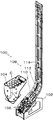
図1は本発明の実施例の回転ディスクを装着したコインホッパの分解斜視図である。
図2は本発明の実施例1の回転ディスクを装着した(保留ボウルを取り除いた)コインホッパの部分平面図である。
図3は、実施例1の回転ディスクの裏面図、斜視図及び裏面斜視図である。
図4は、図2におけるA―A線断面図及び部分拡大図である。
図5は、実施例2の回転ディスクの裏面図、斜視図及び裏面斜視図である。
FIG. 1 is an exploded perspective view of a coin hopper equipped with a rotating disk according to an embodiment of the present invention.
FIG. 2 is a partial plan view of the coin hopper with the rotating disk of Example 1 of the present invention attached (with the storage bowl removed).
FIG. 3 is a rear view, a perspective view, and a rear perspective view of the rotating disk according to the first embodiment.
4 is a cross-sectional view taken along line AA in FIG. 2 and a partially enlarged view.
FIG. 5 is a rear view, a perspective view, and a rear perspective view of the rotating disk according to the second embodiment.
図1を参照してコインホッパ100の構造を説明する。
コインホッパ100はフレーム102と、フレーム102に固定され、かつ、コインCを貯留する筒形の保留ボウル104と、保留ボウル104の下方に配置されたコインCの送り出し用の送り出し部106を有する。
コイン案内装置108は、送り出し部106からディスクCを受け入れる傾斜部110、傾斜部110に接続し、垂直上方へ方向を変える湾曲部112と、湾曲部112に接続し、垂直上方へ延びる直線部114とを有する。
送り出し部106により送り出されたコインCは、順次送り出されるコインCによって押されて傾斜部110、湾曲部112及び直線部114の順に案内され、直線部114の先端から払い出される。
The structure of the
The
The
The coin C sent out by the sending-out
次に図2を参照して送り出し部106を説明する。
送り出し部106は、保留ボウル104の底部に位置する回転ディスク116、スライドベース118、第1ガイドピン120、第2ガイドピン122、ガイドローラ124及び規制ローラ126を含んでいる。
スライドベース118は、回転ディスク116のすぐ下方に位置し、かつ、コインCがスライドする。
第1ガイドピン120及び第2ガイドピン122は、スライドベース118から回転ディスク116に向かって突出し、コインCを出口128へ案内する。
Next, the
The
The
The first guide pin 120 and the
ガイドローラ124は、回転ディスク116の直近側方に固定配置された回転可能なローラであり、第2ガイドピン122によって案内されたコインCをガイドする。
規制ローラ126は、ガイドローラ124に対し接近及び離れる方向に移動可能である。
換言すれば、ガイドローラ124は、付勢手段、例えばスプリングによってガイドローラ124に近づくよう付勢されている。
ガイドローラ124と規制ローラ126との間を通過したコインCは、図示しないガイドによりコイン案内装置108に案内される。
The
The regulating
In other words, the
The coin C that has passed between the
次に回転ディスク116を主に図3を参照して説明する。
回転ディスク116は、円板状であり、その回転中心を中心とする同一円上に等間隔でコインCが通過する通孔130が形成されている。
この回転ディスク116は、軽量化のため、樹脂で成型されているが、所定の強度を確保するため、平板状の金属プレート132が回転ディスク116の厚み方向中間にサンドイッチ状にインサートされている。
Next, the rotating
The rotating
The rotating
この金属プレート132の通孔130を形成する円形エッジは、下向きに凸に形成され、リング状フランジ133を形成し、薄板にも関わらず強度向上と通孔130の摩耗を防止している。
通孔130の間はリブ134により接続されている。
リブ134の下面には、コインCの押進部136が回転ディスク116の周方向かつ回転方向後位側に後退するよう回転ディスク116の中心からインボリュート曲線状に伸びている。
換言すれば、押進部136は各通孔130に相対して設けられている。
The circular edge forming the through
The through
On the lower surface of the
In other words, the pushing portion 136 is provided relative to each through
また、回転ディスク116の下面の中心にはコインCの厚みより僅かに厚い中心部138が形成されている。
中心部138から所定距離離れて中心部138と同じ厚さであり、かつ、図3に示すように矩形状の第1押進部140が形成されている。
中心部138と第1押進部140との間が第1溝142であり、回転ディスク116の中心を中心として弧状に形成され、第1ガイドピン120の先端が位置可能である。
A
A first pushing
A
第1押進部140よりも回転ディスク116の周側に第2ガイドピン122が位置可能な第2溝144が形成されている。
第2溝144は、第1押進部140と押進ローラ146との間に形成される。
押進ローラ146は、回転ディスク116の回転軸線と平行な回転軸線を有する回転自在なローラ150である。
A
The
The pushing roller 146 is a
ローラ150は、コインCと接触して回転する機能を有していれば構造は問わない。
しかし、回転ディスク116の直径は約80ミリであり、また、リブ134の下面に取り付けられるローラ150は最大でも約10ミリであるので、耐久性を有するローラを安価に構成するには、実施例に示す構造が適している。
The
However, the diameter of the
ローラ150は、シリンダ状のローラ部154とその端面のフランジ部156を有し、フランジ部156にはブッシュ孔158が形成されている。
ローラ150は、機械的強度に優れ、かつ、金属との摩擦係数が低いポリアセタール樹脂(POM)により一体成型した場合、円滑な回転が可能であり、かつ、安価であり好ましい。
ブッシュ160は、大径頭部162と小径部166を有し、錆びによる摩擦係数増を防止するため、錆びないステンレス材で作ることが好ましい。
The
When the
The
図4(B)に示すように、ブッシュ160は、回転ディスク116(金属プレート)を上下方向に貫通する取付孔164に回転ディスク116の下面側から小径部166を挿入し、その先端を取付穴164内の段部168にあてがうと共に、回転ディスク116の上面側から皿小ネジ170を挿入し、ブッシュ160の内孔172のネジ部にねじ込むことにより、回転ディスク116に固定されている。
この状態において、大径頭部162の下端面は、スライドベース118に対し1ミリ以下の隙間をもって相対している。
As shown in FIG. 4B, the
In this state, the lower end surface of the large-
ネジ170は、コインCとの接触による緩みを防止するため、回転ディスク116の上面に突出しない皿ネジを用いることが好ましいが、ロック手段を追加することにより、回転ディスク116の上面に突出するネジを用いることができる。
回転ディスク116の上面に突出するネジは、コインCの攪拌効果を有するので好ましい。
回転ディスク116が金属で作られている場合、ブッシュ160はかしめにより固定することができる。
In order to prevent loosening due to contact with the coin C, it is preferable to use a countersunk screw that does not protrude on the upper surface of the
A screw protruding from the upper surface of the
When the
この状態において、ローラ150のフランジ部156は大径頭部162の上面と回転ディスク116の裏面との間に挟まれ、その上下方向の位置が規制される。
すなわち、ブッシュ160の大径頭部162及びローラ150の下端とが面一になる。
この構成において、ネジ170が緩んでブッシュ160が落下した場合、ブッシュ160の大径頭部162の端面はスライドベース118によって支えられ、小径部166は、取付孔164内に位置している。
このため、ブッシュ160は回転ディスク116と一体に回転する。
In this state, the
That is, the large-
In this configuration, when the
For this reason, the
また、ローラ150は、ブッシュ160に支えられて回転可能である。
したがって、通常状態と同様にコインCを払い出すことができる。
さらに、大径頭部162の外周面はローラ150のローラ部154内周面とががたつかないようはまり合い、ほぼ面接触でローラ150を軸受けする。
したがって、ローラ150は、ブッシュ160の大径頭部162にほぼ面接触で受けられ、かつ、金属との摩擦係数が小さいポリアセタール樹脂であるので、コインCとの接触によって回転されることができる。
Further, the
Therefore, the coin C can be paid out as in the normal state.
Further, the outer peripheral surface of the large-
Therefore, since the
ローラ150に隣接し、かつ、回転ディスク116の周縁側に第2押進部174が形成されている。
第2押進部174の突出量は、第1押進部140と同一である。
第1押進部140、ローラ150及び第2押進部174の回転方向前位側の面は、回転ディスク116の回転方向の下流に向かって後退する線176線上又はその近傍に配置されている。
A second pushing
The protrusion amount of the second pushing
The front surface in the rotational direction of the first pushing
この線176は、コインCを滑らかに回転ディスク116の周縁側に押し進めるため、インボリュート曲線が好ましい。
しかし、線176は、回転ディスク116の周縁側ほど回転方向の後位側に位置する関係であればインボリュート曲線で無くとも良い。
The
However, the
ローラ150は、耐久性を向上するため、可及的に大径であることが好ましい。
そのため、本実施例1のローラ150は図3(A)に示すように、回転方向後位の通孔130と線176に接する直径に設定されている。
すなわち、回転方向後位の通孔130に落下するコインCを邪魔しないこと、及び、押進部136による円滑なコインCの押し進めを両立するためである。
したがって、本実施例において押進部136は、第1押進部140、押進ローラ146及び第2押進部174によって構成されている。
The
Therefore, as shown in FIG. 3A, the
In other words, this is to prevent the coin C falling in the through
Therefore, in this embodiment, the pushing portion 136 is constituted by the first pushing
回転ディスク116の軸心部には上下方向に貫通するD形に形成された軸孔178が設けられている。
電気モータ(図示せず)によって回転され、かつ、スライドベース118の裏面に固定された減速機(図示せず)の出力軸(図示せず)が、軸孔178に挿入され、固定される。
A
An output shaft (not shown) of a speed reducer (not shown) rotated by an electric motor (not shown) and fixed to the back surface of the
次にコインCを払い出す際の作用を説明する。
保留ボウル104内に投入されたコインCは、大部分が保留ボウル104の底部に位置する回転ディスク116上に位置する。
回転ディスク116が回転した場合、保留ボウル104内のコインCは攪拌され、通孔130に落下し、スライドベース118上に支持される。
スライドベース118上に支持されたコインCは、押進部136、具体的には第1押進部140により押されて回転ディスク116とともに図2に示すように反時計方向に回動される。
Next, the operation when paying out the coin C will be described.
Most of the coins C placed in the
When the
The coin C supported on the
このとき、第1押進部140は、コインCの周面を押す。
コインCはその外向き面から外周へ向かう力を受けるので、保留ボウル104の下端部の円形内面に案内されつつ回転ディスク116と共に移動する。
コインCが出口128に相対した場合、保留ボウル104の円形内面により案内されないので、前記外周に向かう力により、出口128へ向かって押される。
これにより、コインCは回転ディスク116の周縁側へ移動するので、押進ローラ136にも接触し、押される(図2参照)。
At this time, the first pushing
Since the coin C receives a force from its outward surface toward the outer periphery, the coin C moves with the
When the coin C faces the
As a result, the coin C moves to the peripheral side of the
コインCが出口128へ向かって移動しない場合、第1ガイドピン120及び第2ガイドピン122によって進行を阻止され、出口128へ案内される。
コインCは、出口128においてガイドローラ124に接触した後、さらに押進ローラ146によって押される。
ガイドローラ124は固定であるため、コインCは規制ローラ126をガイドローラ124から遠ざけるよう移動させつつ回転ディスク116の周縁方向へ移動される。
When the coin C does not move toward the
The coin C comes into contact with the
Since the
このとき、コインCは回転ディスク116の回転方向に対してほぼ固定であるので、押進部136はコインCを擦るように相対移動する。
換言すれば、押進部136のコインCとの接触位置は、第1押進部140、押進ローラ146そして第2押進部174の順に移動する。
コインCの押進過程において、押進ローラ146が最も長時間コインCと接する。
At this time, since the coin C is substantially fixed with respect to the rotating direction of the
In other words, the contact position of the pushing portion 136 with the coin C moves in the order of the first pushing
In the pushing process of the coin C, the pushing roller 146 is in contact with the coin C for the longest time.
さらに、コインCは、規制ローラ126に加えられるスプリング力及び案内装置108内のコイン重量及び進行抵抗により、進行抵抗を受ける。
換言すれば、コインCと押進ローラ146との接触圧力が大きくなる。
しかし、ローラ150は回転自在であるので、コインCの相対移動に伴って回転する。
換言すれば、ローラ150はコインCと擦れ合わないので、実質的に摩耗することがない。
Further, the coin C receives a traveling resistance due to the spring force applied to the regulating
In other words, the contact pressure between the coin C and the pushing roller 146 increases.
However, since the
In other words, since the
コインCが第2押進部174によって押されることにより、コインCの直径部がガイドローラ124と規制ローラ126との間を通過するので、規制ローラ126はスプリング力によりガイドローラ124に近づき、所定の位置で停止される。
これにより、ガイドローラ124と規制ローラ126との間を通過したコインCは、回転ディスク116側へ戻ることが出来ず、コイン案内装置108によって案内される。
When the coin C is pushed by the second pushing
As a result, the coin C that has passed between the
次に、実施例2を図5を参照して説明する。
本実施例は、実施例1の第2押進部174を配置せず、押進ローラ146のみを配置した例である。
この場合、押進ローラ146の直径を実施例1よりも大径化でき、耐久性をさらに向上できる利点がある。
すなわち、実施例2のローラ180は、線176、通孔130及び回転ディスク116の外周縁に大凡接する直径に設定することにより、大径化される。
ローラ180の支持構造及び材質は、実施例1と同様であるが、大径化により、ボールベアリング又はニードルベアリング化することができる。
Next, Example 2 will be described with reference to FIG .
In this embodiment, the second pushing
In this case, there is an advantage that the diameter of the pushing roller 146 can be made larger than that of the first embodiment and the durability can be further improved.
That is, the diameter of the
The support structure and material of the
案内装置108を有しないコインホッパは、通常、スプリングにより付勢される規制ローラ126を使用しているので、本発明は案内装置108と組み合わされないコインホッパに使用しても押進部の摩耗を防止できる効果が得られる。
Since the coin hopper that does not have the
Cコイン
104保留ボウル
116回転ディスク
130コイン通孔
136押進部
146押進ローラ
150ローラ
160ブッシュ
162大径頭部
176線
C coin
104 hold bowl
116 rotation disc
130 coin hole
136 Pushing part
146 Pushing roller
150 rollers
160 bush
162 Large diameter head
176 lines
Claims (1)
Priority Applications (4)
| Application Number | Priority Date | Filing Date | Title |
|---|---|---|---|
| JP2004107051A JP4784805B2 (en) | 2004-03-31 | 2004-03-31 | Coin hopper rotating disk |
| EP05001193.1A EP1583045B1 (en) | 2004-03-31 | 2005-01-21 | Rotating disk for a coin dispensing device |
| CN200510053108.8A CN1677446B (en) | 2004-03-31 | 2005-03-02 | Rotating disk for a coin dispensing device |
| US11/091,208 US7144319B2 (en) | 2004-03-31 | 2005-03-28 | Rotating pusher disk for a coin dispensing device |
Applications Claiming Priority (1)
| Application Number | Priority Date | Filing Date | Title |
|---|---|---|---|
| JP2004107051A JP4784805B2 (en) | 2004-03-31 | 2004-03-31 | Coin hopper rotating disk |
Publications (3)
| Publication Number | Publication Date |
|---|---|
| JP2005293207A JP2005293207A (en) | 2005-10-20 |
| JP2005293207A5 JP2005293207A5 (en) | 2007-05-17 |
| JP4784805B2 true JP4784805B2 (en) | 2011-10-05 |
Family
ID=34880092
Family Applications (1)
| Application Number | Title | Priority Date | Filing Date |
|---|---|---|---|
| JP2004107051A Expired - Fee Related JP4784805B2 (en) | 2004-03-31 | 2004-03-31 | Coin hopper rotating disk |
Country Status (4)
| Country | Link |
|---|---|
| US (1) | US7144319B2 (en) |
| EP (1) | EP1583045B1 (en) |
| JP (1) | JP4784805B2 (en) |
| CN (1) | CN1677446B (en) |
Families Citing this family (10)
| Publication number | Priority date | Publication date | Assignee | Title |
|---|---|---|---|---|
| JP4936658B2 (en) * | 2004-11-16 | 2012-05-23 | 株式会社オーイズミ | Coin delivery device |
| JP5234617B2 (en) * | 2008-10-09 | 2013-07-10 | 株式会社タイトー | Hopper device that can pay out two medals at the same time |
| CN102441535B (en) * | 2011-12-05 | 2013-09-11 | 浙江佳丽珍珠首饰有限公司 | Device for continuously collecting fallen pearls |
| US10089812B1 (en) * | 2014-11-11 | 2018-10-02 | Cummins-Allison Corp. | Systems, methods and devices for processing coins utilizing a multi-material coin sorting disk |
| US20170323508A1 (en) * | 2016-05-03 | 2017-11-09 | Elia MARTINEZ | Coin Storage and Display System |
| US10181234B2 (en) | 2016-10-18 | 2019-01-15 | Cummins-Allison Corp. | Coin sorting head and coin processing system using the same |
| US10679449B2 (en) | 2016-10-18 | 2020-06-09 | Cummins-Allison Corp. | Coin sorting head and coin processing system using the same |
| JP6934676B2 (en) * | 2019-01-28 | 2021-09-15 | 旭精工株式会社 | Coin separation and delivery device for coin processing equipment |
| TW202331658A (en) * | 2020-09-15 | 2023-08-01 | 日商旭精工股份有限公司 | Coin hopper, rotor for coin hopper, and coin processing device |
| CN115159138B (en) * | 2022-07-21 | 2023-08-29 | 西安航天发动机有限公司 | Unmanned automatic bowl feeding machine |
Family Cites Families (8)
| Publication number | Priority date | Publication date | Assignee | Title |
|---|---|---|---|---|
| JP2514877B2 (en) | 1991-10-01 | 1996-07-10 | 旭精工株式会社 | Coin sending device with coin escalator |
| ES2102468T3 (en) | 1992-10-27 | 1997-08-01 | Asahi Seiko Co Ltd | COIN FEED DEVICE WITH A CLIMBER. |
| KR970005402B1 (en) * | 1992-11-02 | 1997-04-16 | 아사히 세이꼬 가부시끼가이샤 | Coin feeder |
| US5484334A (en) * | 1994-04-01 | 1996-01-16 | Evdokimo; Allen J. | Coin handling apparatus with coin filter and improved coin interlock |
| JP3175036B2 (en) * | 1994-05-12 | 2001-06-11 | 旭精工株式会社 | Coin receiving / dispensing device |
| JP3792766B2 (en) * | 1996-01-30 | 2006-07-05 | アルゼ株式会社 | Coin dispensing device for gaming machines |
| ES2162693T3 (en) * | 1997-09-12 | 2002-01-01 | Asahi Seiko Co Ltd | APPARATUS FOR DISPENSING CIRCULAR OBJECTS OF SHEET. |
| JP3026806B1 (en) | 1999-04-21 | 2000-03-27 | 弘美 松下 | Disc rotor for transferring coins in hopper type coin dispenser |
-
2004
- 2004-03-31 JP JP2004107051A patent/JP4784805B2/en not_active Expired - Fee Related
-
2005
- 2005-01-21 EP EP05001193.1A patent/EP1583045B1/en active Active
- 2005-03-02 CN CN200510053108.8A patent/CN1677446B/en not_active Expired - Fee Related
- 2005-03-28 US US11/091,208 patent/US7144319B2/en active Active
Also Published As
| Publication number | Publication date |
|---|---|
| JP2005293207A (en) | 2005-10-20 |
| CN1677446B (en) | 2010-09-01 |
| CN1677446A (en) | 2005-10-05 |
| US20050233684A1 (en) | 2005-10-20 |
| EP1583045A1 (en) | 2005-10-05 |
| EP1583045B1 (en) | 2015-06-03 |
| US7144319B2 (en) | 2006-12-05 |
Similar Documents
| Publication | Publication Date | Title |
|---|---|---|
| JP4784805B2 (en) | Coin hopper rotating disk | |
| EP0044640B1 (en) | Coin dispensing apparatus | |
| JP2014146134A (en) | Coin dispensing device | |
| AU758528B2 (en) | A coin dispensing apparatus | |
| US20050003750A1 (en) | Dispensing coin hopper apparatus | |
| JP4499823B2 (en) | Coin hopper | |
| JP4714857B2 (en) | Coin guide for coin hopper | |
| JP5167524B2 (en) | Coin hopper | |
| JP4411383B2 (en) | Coin retrograde device for coin feeding device | |
| JP4604156B2 (en) | Coin dispensing device | |
| JP5481627B2 (en) | Disc ejector | |
| JP4644773B2 (en) | Disk sorting device | |
| JP3049198U (en) | Hopper equipment | |
| JP2006344175A5 (en) | ||
| JP5156930B2 (en) | Coin hopper | |
| JP2010131122A5 (en) | ||
| JP2010049671A5 (en) | ||
| JP5463521B2 (en) | Disk-shaped body feeding device | |
| JP5092095B2 (en) | Coin hopper guide | |
| JP4348060B2 (en) | Medal transfer passage | |
| JP5492940B2 (en) | Disk-shaped body feeding device | |
| KR20200061052A (en) | Rack bar support structure with noise reduction function | |
| US2729111A (en) | Wire guide device | |
| JPH0952637A (en) | Delivering device | |
| JPH0457036B2 (en) |
Legal Events
| Date | Code | Title | Description |
|---|---|---|---|
| A521 | Request for written amendment filed |
Free format text: JAPANESE INTERMEDIATE CODE: A523 Effective date: 20070323 |
|
| A621 | Written request for application examination |
Free format text: JAPANESE INTERMEDIATE CODE: A621 Effective date: 20070323 |
|
| A977 | Report on retrieval |
Free format text: JAPANESE INTERMEDIATE CODE: A971007 Effective date: 20100205 |
|
| A131 | Notification of reasons for refusal |
Free format text: JAPANESE INTERMEDIATE CODE: A131 Effective date: 20100319 |
|
| A521 | Request for written amendment filed |
Free format text: JAPANESE INTERMEDIATE CODE: A523 Effective date: 20100514 |
|
| A131 | Notification of reasons for refusal |
Free format text: JAPANESE INTERMEDIATE CODE: A131 Effective date: 20101210 |
|
| A521 | Request for written amendment filed |
Free format text: JAPANESE INTERMEDIATE CODE: A523 Effective date: 20101217 |
|
| TRDD | Decision of grant or rejection written | ||
| A01 | Written decision to grant a patent or to grant a registration (utility model) |
Free format text: JAPANESE INTERMEDIATE CODE: A01 Effective date: 20110629 |
|
| A01 | Written decision to grant a patent or to grant a registration (utility model) |
Free format text: JAPANESE INTERMEDIATE CODE: A01 |
|
| A61 | First payment of annual fees (during grant procedure) |
Free format text: JAPANESE INTERMEDIATE CODE: A61 Effective date: 20110629 |
|
| R150 | Certificate of patent or registration of utility model |
Ref document number: 4784805 Country of ref document: JP Free format text: JAPANESE INTERMEDIATE CODE: R150 Free format text: JAPANESE INTERMEDIATE CODE: R150 |
|
| FPAY | Renewal fee payment (event date is renewal date of database) |
Free format text: PAYMENT UNTIL: 20140722 Year of fee payment: 3 |
|
| R250 | Receipt of annual fees |
Free format text: JAPANESE INTERMEDIATE CODE: R250 |
|
| R250 | Receipt of annual fees |
Free format text: JAPANESE INTERMEDIATE CODE: R250 |
|
| R250 | Receipt of annual fees |
Free format text: JAPANESE INTERMEDIATE CODE: R250 |
|
| R250 | Receipt of annual fees |
Free format text: JAPANESE INTERMEDIATE CODE: R250 |
|
| R250 | Receipt of annual fees |
Free format text: JAPANESE INTERMEDIATE CODE: R250 |
|
| R250 | Receipt of annual fees |
Free format text: JAPANESE INTERMEDIATE CODE: R250 |
|
| R250 | Receipt of annual fees |
Free format text: JAPANESE INTERMEDIATE CODE: R250 |
|
| R250 | Receipt of annual fees |
Free format text: JAPANESE INTERMEDIATE CODE: R250 |
|
| LAPS | Cancellation because of no payment of annual fees |