JP4784571B2 - Fuel injection control device - Google Patents
Fuel injection control device Download PDFInfo
- Publication number
- JP4784571B2 JP4784571B2 JP2007200457A JP2007200457A JP4784571B2 JP 4784571 B2 JP4784571 B2 JP 4784571B2 JP 2007200457 A JP2007200457 A JP 2007200457A JP 2007200457 A JP2007200457 A JP 2007200457A JP 4784571 B2 JP4784571 B2 JP 4784571B2
- Authority
- JP
- Japan
- Prior art keywords
- injection
- fuel
- diesel engine
- amount
- pilot
- Prior art date
- Legal status (The legal status is an assumption and is not a legal conclusion. Google has not performed a legal analysis and makes no representation as to the accuracy of the status listed.)
- Expired - Fee Related
Links
- 238000002347 injection Methods 0.000 title claims description 209
- 239000007924 injection Substances 0.000 title claims description 209
- 239000000446 fuel Substances 0.000 title claims description 121
- 238000002485 combustion reaction Methods 0.000 claims description 15
- 238000001514 detection method Methods 0.000 claims description 5
- 239000002828 fuel tank Substances 0.000 description 4
- 230000007423 decrease Effects 0.000 description 3
- 230000003247 decreasing effect Effects 0.000 description 3
- 238000010586 diagram Methods 0.000 description 3
- 238000004590 computer program Methods 0.000 description 2
- 230000002542 deteriorative effect Effects 0.000 description 2
- 238000000034 method Methods 0.000 description 2
- 238000000520 microinjection Methods 0.000 description 2
- 238000009825 accumulation Methods 0.000 description 1
- 239000000498 cooling water Substances 0.000 description 1
- 238000006073 displacement reaction Methods 0.000 description 1
- 238000010992 reflux Methods 0.000 description 1
- 230000011218 segmentation Effects 0.000 description 1
Images


Description
本発明は、ディーゼルエンジンの燃料噴射制御装置に関する。 The present invention relates to a fuel injection control device for a diesel engine.
ディーゼルエンジンでは、燃焼室における燃料の燃焼状態の改善を目的として主たる燃料の噴射であるメイン噴射に先立って、微量の燃料を噴射するパイロット噴射が実施されている。パイロット噴射はメイン噴射における燃料の噴射量に比較して微量であるため、インジェクタから噴射される燃料を精密に制御する必要がある。そこで、インジェクタから噴射可能な微量の燃料噴射量を学習する燃料噴射制御装置が提案されている(特許文献1、2参照)。
In a diesel engine, pilot injection for injecting a small amount of fuel is performed prior to main injection, which is main fuel injection, for the purpose of improving the combustion state of fuel in a combustion chamber. Since pilot injection is very small compared to the amount of fuel injected in main injection, it is necessary to precisely control the fuel injected from the injector. Therefore, a fuel injection control device that learns a small amount of fuel injection that can be injected from an injector has been proposed (see
特許文献1では、ディーゼルエンジンのアイドリング運転時において、アイドリングの維持に必要な燃料をn回に分割して噴射している。燃料の噴射量をn回に分割することにより、一回の噴射当たりの燃料を低減しつつ、ディーゼルエンジンの回転数と目標回転数との差から微量の燃料噴射量を学習している。また、特許文献2では、メイン噴射における燃料噴射量をディーゼルエンジンの気筒間で調整した後、パイロット噴射における燃料噴射量を調整している。
しかしながら、例えば大型車に搭載されている大型のディーゼルエンジンの場合、アイドリングを維持するために必要な燃料の噴射量は大きくなる。そのため、特許文献1のようにアイドリングに必要な燃料をn回に分割して噴射する場合、一回当たりの燃料噴射量は大きくなる。微量の燃料噴射量を学習する場合、インジェクタから噴射される燃料量は可能な限り微量であることが望ましい。すなわち、インジェクタから噴射可能な最小限度の燃料量を学習することが望ましい。一方、所定の噴射時期においてインジェクタから燃料を噴射可能な期間には限度がある。その結果、一回当たりの燃料噴射量が大きな大型のディーゼルエンジンの場合、噴射回数の増大による一回当たりの燃料噴射量の減量は困難である。また、特許文献2の場合、メイン噴射のみを調整した後、メイン噴射にパイロット噴射を含めて調整する。そのため、ディーゼルエンジンの運転中に、メイン噴射のみの燃料噴射パターンとパイロット噴射およびメイン噴射からなる燃料噴射パターンとが切り替えられる。その結果、燃料噴射パターンの切替時において、燃焼音の変化や発生トルクの変化などを招き、ディーゼルエンジンの運転性が悪化するという問題がある。
However, for example, in the case of a large diesel engine mounted on a large vehicle, the amount of fuel injection required to maintain idling increases. Therefore, when the fuel required for idling is divided into n times and injected as in
そこで、本発明は、上記の課題に鑑みてなされたものであり、その目的は、運転性の悪化を招くことなく、ディーゼルエンジンの排気量に関わらずインジェクタからの微量の燃料噴射量の学習を実施する燃料噴射制御装置を提供することにある。 Accordingly, the present invention has been made in view of the above problems, and its purpose is to learn a small amount of fuel injection from an injector regardless of the displacement of a diesel engine without deteriorating drivability. An object of the present invention is to provide a fuel injection control device to be implemented.
請求項1記載の発明では、噴射パターン設定手段は、メイン噴射とパイロット噴射をn回に分割した分割パイロット噴射とからなる噴射パターンを設定する。パイロット噴射における微量の噴射量の学習を実施する場合、パイロット噴射量減量手段は、燃焼行程ごとに分割パイロット噴射における一回当たりの噴射量を徐々に減量する。回転変化手段は、分割パイロット噴射における噴射量の減量にともなうディーゼルエンジンの回転の変化を検出する。インジェクタから噴射される燃料を徐々に減量する場合、ある時期を境に燃料の噴射が消滅する。この燃料の噴射が消滅する直前の噴射量は、インジェクタから噴射される燃料の最小量すなわち下限値となる。このとき、分割パイロット噴射の回数は予めn回に設定されているため、噴射回数の増大および噴射一回当たりの燃料量の増加を招くことはない。一方、燃料の噴射が消滅すると、ディーゼルエンジンの回転に変化が生じる。そこで、パイロット噴射量増量手段は、ディーゼルエンジンの回転に変化が生じると、分割パイロット噴射における一回当たりの噴射量を増量する。これにより、ディーゼルエンジンは、安定した運転が維持される。したがって、運転性の悪化を招くことなく、ディーゼルエンジンの排気量に関わらずインジェクタからの微量の燃料噴射量の学習を実施することができる。 In the first aspect of the present invention, the injection pattern setting means sets an injection pattern composed of divided pilot injection obtained by dividing main injection and pilot injection into n times. When learning a small amount of injection in pilot injection, the pilot injection amount reduction means gradually reduces the injection amount per time in divided pilot injection for each combustion stroke. The rotation change means detects a change in the rotation of the diesel engine accompanying a decrease in the injection amount in the divided pilot injection. When the amount of fuel injected from the injector is gradually reduced, the fuel injection disappears after a certain period. The injection amount immediately before the fuel injection disappears becomes the minimum amount of fuel injected from the injector, that is, the lower limit value. At this time, since the number of divided pilot injections is set to n in advance, there is no increase in the number of injections and an increase in the amount of fuel per injection. On the other hand, when the fuel injection disappears, a change occurs in the rotation of the diesel engine. Therefore, the pilot injection amount increasing means increases the injection amount per time in the divided pilot injection when a change occurs in the rotation of the diesel engine. As a result, the diesel engine is maintained in stable operation. Therefore, a small amount of fuel injection from the injector can be learned regardless of the exhaust amount of the diesel engine without deteriorating drivability.
請求項2記載の発明では、ディーゼルエンジンの各気筒ごとにインジェクタから噴射される微量の燃料の噴射量を学習している。したがって、各気筒間でのインジェクタごとの個体差、あるいは経年変化に関わらず、インジェクタからの微量の燃料噴射量の学習を実施することができる。 In the invention according to the second aspect, the injection amount of a small amount of fuel injected from the injector is learned for each cylinder of the diesel engine. Therefore, it is possible to learn a small amount of fuel injection from the injector regardless of individual differences among the injectors among the cylinders or changes over time.
以下、本発明の一実施形態による燃料噴射装置を図面に基づいて説明する。
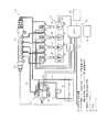
図1は、本発明の一実施形態による燃料噴射制御装置を適用した燃料噴射システム示す概略図である。本実施形態の場合、燃料噴射制御装置10は、コモンレール式の燃料噴射システム20により燃料の噴射が制御されるディーゼルエンジン21に適用される。燃料噴射システム20は、燃料タンク22、吸入量制御弁23、サプライポンプ24、コモンレール25およびインジェクタ40を備えている。燃料噴射制御装置10は、エンジン制御装置(以下、「ECU:Engine Control Unit」という。)11と、電子駆動装置(以下、「EDU:Electronic Drive Unit」という。)12とから構成されている。吸入量制御弁23およびサプライポンプ24は、一体のポンプユニット27を構成している。
Hereinafter, a fuel injection device according to an embodiment of the present invention will be described with reference to the drawings.
FIG. 1 is a schematic view showing a fuel injection system to which a fuel injection control device according to an embodiment of the present invention is applied. In the present embodiment, the fuel
燃料タンク22は、常圧の燃料を蓄えている。燃料タンク22の内部の燃料は、図示しない低圧ポンプにより吸入配管部31を経由して吸入量制御弁23へ供給される。サプライポンプ24は、図示しないプランジャが往復移動することにより、図示しない加圧室に吸入した燃料を加圧する。サプライポンプ24では、加圧室へ吸入される燃料の流量に応じて吐出される燃料の流量が変化する。プランジャは、ディーゼルエンジン21のクランクシャフト28から駆動力が伝達される。サプライポンプ24で加圧された燃料は、コモンレール25へ吐出される。サプライポンプ24の吐出側には、燃料配管部32が接続している。燃料配管部32は、サプライポンプ24とコモンレール25とを接続している。
The
コモンレール25は、燃料配管部32と接続され、サプライポンプ24で加圧された燃料を蓄圧状態で蓄える。コモンレール25には、ディーゼルエンジン21の各気筒29へ燃料を噴射するインジェクタ40が接続している。インジェクタ40は、各気筒29にそれぞれ設けられている。コモンレール25に蓄圧状態で蓄えられた燃料は、インジェクタ40から各気筒29に形成されている燃焼室へ噴射される。サプライポンプ24、コモンレール25およびインジェクタ40には、還流配管部33が接続している。サプライポンプ24、コモンレール25およびインジェクタ40で余剰となった燃料は、還流配管部33を経由して燃料タンク22へ戻される。
The
ECU11およびEDU12は、例えばCPU、ROMおよびRAMを有するマイクロコンピュータで構成されている。CPUは、ROMに格納されているコンピュータプログラムにしたがって燃料噴射システム20の全体を制御する。ECU11は、入力側の回路に圧力センサ13、アクセルセンサ14および回転センサ15などが接続している。圧力センサ13は、コモンレール25に設けられている。圧力センサ13は、コモンレール25に蓄えられている燃料の圧力を検出する。
ECU11 and EDU12 are comprised by the microcomputer which has CPU, ROM, and RAM, for example. The CPU controls the entire
圧力センサ13は、検出したコモンレール25における燃料の圧力を電気信号としてECU11へ出力する。アクセルセンサ14は、図示しないアクセルペダルの踏み込み量を電気信号としてECU11へ出力する。回転センサ15は、ディーゼルエンジン21のクランクシャフト28の回転を検出する。回転センサ15は、検出したクランクシャフト28の回転を電気信号としてECU11へ出力する。
The
ECU11は、例えば回転センサ15で検出したディーゼルエンジン21の回転状態に関する電気信号、およびアクセルセンサ14で検出したアクセルペダルの踏み込み量などから、ディーゼルエンジン21の運転状態を検出する。ECU11は、検出したディーゼルエンジン21の運転状態に応じてインジェクタか26ら噴射される燃料の噴射量を設定する。ECU11は、設定した燃料の噴射量に基づいて、コモンレール25において必要となる燃料の圧力を設定する。
The ECU 11 detects the operating state of the
ECU11は、出力側の回路に吸入量制御弁23およびEDU12などが接続している。吸入量制御弁23は、ECU11から出力された制御電流に基づいてサプライポンプ24へ供給する燃料の流量を制御する。EDU12は、インジェクタ40の電磁弁41に接続している。EDU12は、ECU11から出力された駆動信号に基づいてインジェクタ40の電磁弁41へパルス状の駆動信号を出力する。インジェクタ40は、EDU12から出力されたパルス状の駆動信号に基づいて電磁弁41が駆動され、燃料の噴射が断続される。その結果、インジェクタ40は、コモンレール25に蓄えられている燃料をディーゼルエンジン21の各気筒29に形成されている燃焼室へ噴射する。
In the
ECU12には、記憶部16が接続している。記憶部16は、例えばEEPROM(Electrical Erasable Programmable Read Only Memory)などの不揮発性の記憶装置などを有している。記憶部16は、ECU12で使用されるデータやECU11で実行されるコンピュータプログラムなどを記憶している。なお、記憶部16は、ECU11のROMやRAMと共用してもよい。
ECU11は、特許請求の範囲における噴射パターン設定手段、パイロット噴射量減量手段およびパイロット噴射量増量手段を構成している。また、ECU11は、回転センサ15とともに特許請求の範囲における回転変化検出手段を構成している。
A
The
次に、上記の構成による燃料噴射制御装置10の作動について説明する。
(燃料噴射パターン)
燃料噴射制御装置10は、インジェクタ40からの燃料噴射パターンとして、図2に示すように通常噴射パターンと分割パイロット噴射パターンとを設定する。通常噴射パターンは、一回のパイロット噴射と、パイロット噴射に続くメイン噴射とから構成される。メイン噴射における燃料の噴射量は、パイロット噴射に比較して多く設定されている。分割パイロット噴射パターンは、複数回に分割された分割パイロット噴射と、分割パイロット噴射に続くメイン噴射とから構成される。分割パイロット噴射は、通常噴射パターンにおける総噴射量の一部を按分してn回に分割したものである。分割パイロット噴射における一回当たりの分割パイロット噴射量Qは、ディーゼルエンジン21の運転状態に応じてECU11で設定される。なお、分割パイロット噴射における一回当たりの分割パイロット噴射量Qの初期値は最小噴射量の設計値に設定可能であり、通常噴射パターンにおける総噴射量と分割パイロット噴射パターンにおける総噴射量とは、ほぼ同等の値になるよう設定される。
Next, the operation of the fuel
(Fuel injection pattern)
The fuel
(燃料の噴射)
ECU11は、EDU12を経由してインジェクタ40の電磁弁41にパルス状の駆動信号を出力する。インジェクタ40から噴射される燃料の量は、インジェクタ40の電磁弁41の開弁時間、すなわち駆動信号のパルス幅によって制御される。インジェクタ40から噴射される燃料の量は、図3に示すように駆動信号のパルス幅が長くなるにしたがって増大する。ディーゼルエンジン21が複数の気筒29を有する場合、インジェクタ40は各気筒29にそれぞれ一本ずつ取り付けられている。そのため、例えば四気筒のディーゼルエンジン21の場合、四本のインジェクタ40を備えている。各気筒29に取り付けられているインジェクタ40は、個体差によって個々に燃料噴射特性が異なっている。そのため、図3に示すように、インジェクタ40から噴射される燃料の量と駆動電流のパルス幅との関係は、インジェクタ40ごとに異なっている。
(Fuel injection)
The
インジェクタ40の電磁弁41は、電気的および機械的な特性により、駆動信号のパルスを印加しても、駆動信号のパルス幅が所定の値に達するまで作動しない。この場合、インジェクタ40の電磁弁41が作動し、インジェクタ40から燃料が噴射される駆動信号の最小のパルス幅が、インジェクタ40からの燃料の噴射量が最小となるときのパルス幅に対応する。
Due to electrical and mechanical characteristics, the
(微量噴射量の学習)
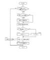
上記の構成の燃料噴射装置による微量噴射量の学習の手順について、図4に基づいて説明する。微量噴射量の学習は、ディーゼルエンジン21の各気筒に設けられているインジェクタ40ごとに実施される。
ECU11は、ディーゼルエンジン21の運転中において所定のタイミングになると、微量噴射量学習のルーチンへ移行する。微量噴射学習のルーチンに移行すると、ECU11は分割パイロット噴射を実施する条件が成立しているか否かを判断する(S101)。ECU11は、ディーゼルエンジン21が安定したアイドリング状態にあるか否かを検出する。ECU11は、例えばアクセルセンサ14で検出したアクセルペダルの踏み込み量が「0」であり、回転センサ15で検出したディーゼルエンジン21の回転数が予め設定されているアイドリング回転数であるとき、ディーゼルエンジン21はアイドリング状態であると判断する。そして、このディーゼルエンジン21のアイドリング状態が所定期間継続すると、ECU11はディーゼルエンジン21が安定したアイドリング状態にあると判断する。なお、ECU11は、アクセルペダルの踏み込み量およびディーゼルエンジン21の回転数だけでなく、例えばスロットル開度、冷却水温あるいは車両のその他の各種のセンサからディーゼルエンジン21の運転状態を検出する構成としてもよい。
(Learning of micro injection amount)
A procedure for learning a minute injection amount by the fuel injection device having the above-described configuration will be described with reference to FIG. The learning of the small amount of injection is performed for each
When the
ECU11は、ステップS101において分割パイロット噴射を実施する条件が成立していると判断すると、前回のルーチンで分割パイロット噴射量Qを記憶しているか否かを判断する(S102)。ECU11は、ルーチンごとに学習した分割パイロット噴射量Qを記憶部16に記憶している。したがって、ECU11は、記憶部16に分割パイロット噴射量Qの記憶があるか否かを判断する。一方、ECU11は、ステップS101において分割パイロット噴射を実施する条件が成立していないと判断すると、ステップS111へ移行し、通常噴射パターンにしたがって燃料の噴射を実施する。
When the
ECU11は、ステップS102において分割パイロット噴射量Qの記憶があると判断すると、記憶部16から前回のルーチンで記憶した分割パイロット噴射量Qを読み取る(S103)。一方、ECU11は、ステップS103において分割パイロット噴射量Qの記憶がないと判断したとき、ステップS103における分割パイロット噴射量Qの読み取りを行うことなく、次のステップへ移行する。
ECU11は、ステップS103において分割パイロット噴射量Qを読み取ると、ディーゼルエンジン21の複数の気筒29間における回転偏差を検出する(S104)。また、分割パイロット噴射量Qが記憶されておらず、ステップS103の処理を省略した場合でも、ECU11はステップS104に移行して気筒29間の回転偏差を検出する。
When the
When the
ECU11は、回転センサ15からクランクシャフト28の回転角度を検出している。このとき、単位時間当たりのクランクシャフト28の回転角度は、クランクシャフト28の回転速度に相当する。ディーゼルエンジン21に複数の気筒29が設けられている場合、図5の期間t1に示すように各気筒29において燃料が燃焼するごと、すなわち各気筒29の燃焼行程ごとにクランクシャフト28の回転速度は大きくなる。そのため、クランクシャフト28の回転速度は、各気筒29における燃焼に対応して所定の範囲内で周期的に変化する。このとき、各気筒29において燃料が均一に燃焼していると、各気筒29間におけるクランクシャフト28の回転速度の差すなわちクランクシャフト28の回転偏差は小さくなる。
The
一方、複数の気筒29のうちいずれかの気筒29においてインジェクタ40から燃料が噴射されない場合、その気筒29では燃料の燃焼が行われない。そのため、燃料が噴射されない気筒29の燃焼行程に対応する期間では、図5の期間t2に示すようにクランクシャフト28の回転速度が低下する。その結果、複数の気筒29間における回転偏差は大きくなる。
ECU11は、気筒29間の回転偏差を検出すると、検出した回転偏差が所定の閾値Dよりも小さいか否かを判断する(S105)。気筒29間の回転偏差が閾値Dよりも小さいとき、ディーゼルエンジン21の各気筒29にインジェクタ40から噴射される燃料の量には不足がない。そのため、前回のルーチンで設定された分割パイロット噴射量Qは、インジェクタ40から噴射可能な量であると判断される。
On the other hand, when fuel is not injected from the
When detecting the rotation deviation between the
そこで、ECU11は、ステップS105において回転偏差が閾値Dよりも小さいと判断したとき、前回のルーチンで設定した分割パイロット噴射量Qから所定量αを減量し、新たな分割パイロット噴射量Qを設定する(S106)。そして、設定した新たな分割パイロット噴射量Qに基づいて、インジェクタ40から燃料の噴射を実施する(S107)。
一方、気筒29間の回転偏差が閾値Dよりも大きいとき、ディーゼルエンジン21のいずれかの気筒29ではインジェクタ40から噴射される燃料の量が不足していることになる。そのため、前回のルーチンで設定された分割パイロット噴射量Qは、インジェクタ40から噴射不可能な量、すなわちインジェクタ40から噴射可能な下限値以下であると判断される。
Therefore, when the
On the other hand, when the rotational deviation between the
そこで、ECU11は、ステップS105において回転偏差が閾値Dよりも大きいと判断したとき、ディーゼルエンジン21の前回のルーチンで設定した分割パイロット噴射量Qに所定量βを増量する(S121)。分割パイロット噴射量Qがインジェクタ40から噴射可能な下限値以下であるとき、ディーゼルエンジン21は安定した運転の継続が困難となる。そのため、ECU11は、分割パイロット噴射量Qに所定量βを加えて、分割パイロット噴射量を再設定する。
ECU11は、ステップS106およびステップS121において新たな分割パイロット噴射量Qを設定すると、設定した分割パイロット噴射量Qに応じてインジェクタ40からディーゼルエンジン21の各気筒29へ燃料の噴射を実施する(S107)。これとともに、ECU11は、設定した分割パイロット噴射量Qを記憶部16に書き込む(S108)。
Therefore, when the
When the
上述の微量噴射量の学習では、図6に示すように燃料の噴射時期ごと、すなわち燃焼行程ごとに、分割されたパイロット噴射における燃料量すなわち分割パイロット噴射量Qが徐々に減量される。そして、分割パイロット噴射量Qの減量によって気筒29間の回転偏差が所定の閾値Dより大きくなったとき、クランクシャフト28の回転速度が低下した気筒29に設けられているインジェクタ40は燃料噴射量が下限値以下となったと判断される。
In the above-described learning of the minute injection amount, as shown in FIG. 6, the fuel amount in the divided pilot injection, that is, the divided pilot injection amount Q is gradually reduced at every fuel injection timing, that is, every combustion stroke. When the rotational deviation between the
図5に示す噴射順序が第一気筒(#1)→第三気筒(#3)→第四気筒(#4)→第二気筒(#2)の四気筒エンジンの例の場合、回転偏差が小さい期間t1では、第一気筒(#1)、第三気筒(#3)、第四気筒(#4)および第二気筒(#2)において回転速度に大きな影響を与えることなく順に燃料の燃焼が行われている。しかし、期間t2では、第四気筒(#4)と他の第一気筒(#1)、第三気筒(#3)および第二気筒(#2)との間に回転偏差が生じている。このとき、第四気筒(#4)では、分割パイロット噴射量Qがインジェクタ40から噴射される燃料の下限値以下となったと考えられる。
If the injection sequence shown in FIG. 5 is an example of a four-cylinder engine in which the first cylinder (# 1) → the third cylinder (# 3) → the fourth cylinder (# 4) → the second cylinder (# 2), the rotational deviation is In the small period t1, the first cylinder (# 1), the third cylinder (# 3), the fourth cylinder (# 4), and the second cylinder (# 2) burn the fuel in order without significantly affecting the rotational speed. Has been done. However, during the period t2, there is a rotational deviation between the fourth cylinder (# 4) and the other first cylinder (# 1), the third cylinder (# 3), and the second cylinder (# 2). At this time, in the fourth cylinder (# 4), it is considered that the divided pilot injection amount Q is equal to or less than the lower limit value of the fuel injected from the
このとき、第四気筒(#4)のインジェクタ40は、分割パイロット噴射量Q以下では燃料を噴射できないと考えられる。そのため、ECU11は、このときの分割パイロット噴射量Qを、第四気筒(#4)における微量燃料噴射量の下限値として学習する。このような分割パイロット噴射量Qの減量を各インジェクタ40ごとに独立して実施することにより、ECU11はディーゼルエンジン21の各気筒29に設けられているインジェクタ40ごとに微量燃料噴射量の下限値を学習する。
At this time, it is considered that the
以上説明した一実施形態では、分割パイロット噴射量Qを徐々に減量することにより、インジェクタ40から燃料が噴射されない噴射量の下限値が検出される。この検出した噴射量の下限値をインジェクタ40ごとに学習することにより、インジェクタ40ごとの燃料噴射量の下限値の個体差、および燃料噴射量の経時的な変化が取得される。したがって、インジェクタ40の個体差および経時的な変化に応じて、インジェクタ40からの微量な燃料噴射量を精密に制御することができる。
また、一実施形態では、パイロット噴射の回数を変更することなく分割パイロット噴射量Qのみを減量している。そのため、燃料の噴射量、燃料の噴射期間に制限されることなく、インジェクタ40からの燃料噴射量の下限値が検出される。したがって、ディーゼルエンジン21の排気量に関わらずインジェクタ40からの微量の燃料噴射量の学習を実施することができる。
In the embodiment described above, the lower limit value of the injection amount at which fuel is not injected from the
Further, in one embodiment, only the divided pilot injection amount Q is reduced without changing the number of pilot injections. Therefore, the lower limit value of the fuel injection amount from the
さらに、一実施形態では、ディーゼルエンジン21の複数の気筒29のうちいずれかの気筒29における燃料の燃焼によってクランクシャフト28の回転に差が生じたとき、その気筒29に噴射される燃料の分割パイロット噴射量Qを増量している。そのため、他の気筒29の燃焼に影響を与えることなく、インジェクタ40からの燃料噴射量の下限値が検出される。したがって、ディーゼルエンジン21の運転性に与える影響を低減することができる。
Furthermore, in one embodiment, when a difference occurs in the rotation of the
以上説明した本発明の一実施形態では、四気筒のディーゼルエンジン21を例に説明した。しかし、ディーゼルエンジン21の気筒29の数は、当然四つに限るものではなく、任意に設定することができる。
以上説明した本発明は、上記実施形態に限定されるものではなく、その要旨を逸脱しない範囲で種々の実施形態に適用可能である。
In the embodiment of the present invention described above, the four-
The present invention described above is not limited to the above-described embodiment, and can be applied to various embodiments without departing from the gist thereof.
図面中、10は燃料噴射制御装置、11はECU(噴射パターン設定手段、パイロット噴射量減量手段、回転変化検出手段、パイロット噴射量増量手段)、15は回転センサ(回転変化検出手段)、21はディーゼルエンジン、29は気筒、40はインジェクタを示す。 In the drawings, 10 is a fuel injection control device, 11 is an ECU (injection pattern setting means, pilot injection amount reduction means, rotation change detection means, pilot injection amount increase means), 15 is a rotation sensor (rotation change detection means), and 21 is A diesel engine, 29 is a cylinder, and 40 is an injector.
Claims (2)
前記ディーゼルエンジンシステムが所定の運転状態に移行したことを検出すると、前記パイロット噴射を噴射量が同一のn回に分割し、n回の分割パイロット噴射およびメイン噴射からなる噴射パターンを設定する噴射パターン設定手段と、
前記噴射パターン設定手段で設定された前記分割パイロット噴射における一回当たりの噴射量を、分割したn回の分割パイロット噴射について一律に、燃焼行程ごとに徐々に減量するパイロット噴射量減量手段と、
前記ディーゼルエンジンの回転の変化を検出する回転変化検出手段と、
前記パイロット噴射量減量手段による前記分割パイロット噴射における噴射量の減量にともなって、前記回転変化検出手段で前記ディーゼルエンジンの回転の変化を検出すると、前記分割パイロット噴射における一回当たりの噴射量を所定量増量するパイロット噴射量増量手段と、を備え、
前記ディーゼルエンジンの回転の変化を検出した前記分割パイロット噴射における一回当たりの噴射量を、前記インジェクタから噴射する燃料の微量燃料噴射量の下限値として学習することを特徴とする燃料噴射制御装置。 In a diesel engine system including an injector for injecting fuel into a combustion chamber formed in a cylinder of a diesel engine, fuel injection from the injector is controlled, and main fuel for combustion is supplied during a single combustion stroke in the combustion chamber. A fuel injection control device that performs main injection to be injected and pilot injection to inject a smaller amount of fuel than the main injection prior to the main injection,
When it is detected that the diesel engine system has shifted to a predetermined operation state, the pilot injection is divided into n injections having the same injection amount, and an injection pattern is set that includes n divided pilot injections and main injections. Setting means;
A pilot injection amount reduction means for gradually reducing the injection quantity per injection in the divided pilot injection set by the injection pattern setting means uniformly for each of the divided n pilot injections;
A rotation change detecting means for detecting a change in rotation of the diesel engine;
When a change in the rotation of the diesel engine is detected by the rotation change detecting means as the injection quantity is reduced in the divided pilot injection by the pilot injection quantity reducing means, the injection quantity per one injection in the divided pilot injection is determined. A pilot injection amount increasing means for quantitatively increasing ,
A fuel injection control device that learns an injection amount per injection in the divided pilot injection in which a change in the rotation of the diesel engine is detected as a lower limit value of a small amount of fuel injected from the injector .
Priority Applications (1)
| Application Number | Priority Date | Filing Date | Title |
|---|---|---|---|
| JP2007200457A JP4784571B2 (en) | 2007-08-01 | 2007-08-01 | Fuel injection control device |
Applications Claiming Priority (1)
| Application Number | Priority Date | Filing Date | Title |
|---|---|---|---|
| JP2007200457A JP4784571B2 (en) | 2007-08-01 | 2007-08-01 | Fuel injection control device |
Publications (2)
| Publication Number | Publication Date |
|---|---|
| JP2009036067A JP2009036067A (en) | 2009-02-19 |
| JP4784571B2 true JP4784571B2 (en) | 2011-10-05 |
Family
ID=40438209
Family Applications (1)
| Application Number | Title | Priority Date | Filing Date |
|---|---|---|---|
| JP2007200457A Expired - Fee Related JP4784571B2 (en) | 2007-08-01 | 2007-08-01 | Fuel injection control device |
Country Status (1)
| Country | Link |
|---|---|
| JP (1) | JP4784571B2 (en) |
Families Citing this family (3)
| Publication number | Priority date | Publication date | Assignee | Title |
|---|---|---|---|---|
| JP5690181B2 (en) * | 2011-03-22 | 2015-03-25 | 富士重工業株式会社 | Fuel injection control device |
| US9599062B2 (en) * | 2014-07-28 | 2017-03-21 | Ford Global Technologies, Llc | Method of pilot injection control |
| JP7413970B2 (en) | 2020-10-12 | 2024-01-16 | 株式会社豊田自動織機 | Internal combustion engine control system |
Family Cites Families (2)
| Publication number | Priority date | Publication date | Assignee | Title |
|---|---|---|---|---|
| JP4089244B2 (en) * | 2002-03-01 | 2008-05-28 | 株式会社デンソー | Injection amount control device for internal combustion engine |
| JP3966206B2 (en) * | 2003-03-28 | 2007-08-29 | マツダ株式会社 | Engine control device |
-
2007
- 2007-08-01 JP JP2007200457A patent/JP4784571B2/en not_active Expired - Fee Related
Also Published As
| Publication number | Publication date |
|---|---|
| JP2009036067A (en) | 2009-02-19 |
Similar Documents
| Publication | Publication Date | Title |
|---|---|---|
| JP4775342B2 (en) | Fuel injection control device and fuel injection system using the same | |
| US7201148B2 (en) | Pressure accumulation fuel injection controller | |
| EP1319821A2 (en) | Fuel injection system having fuel recirculating structure | |
| JP5293775B2 (en) | Engine control system, fuel injection device, and injection drive device | |
| JP4349451B2 (en) | Fuel injection control device and fuel injection system using the same | |
| JP6090112B2 (en) | Control device for internal combustion engine | |
| JP2005171931A (en) | Fuel injection control device | |
| JP4784571B2 (en) | Fuel injection control device | |
| JP2010031720A (en) | Abnormality detection device | |
| JP4529892B2 (en) | Fuel injection control device for multi-cylinder engine | |
| JP4605182B2 (en) | Pump control device and fuel injection system using the same | |
| JP2007332816A (en) | Fuel injection control device | |
| JP2005248739A (en) | Injection amount learning control device | |
| JP4735620B2 (en) | Injection amount learning device | |
| JP2007100626A (en) | Control device for fuel injection system | |
| JP2008202593A (en) | Fuel injection control device | |
| JP4882883B2 (en) | Fuel injection control device and fuel injection system using the same | |
| JP2007023796A (en) | Fuel injection device | |
| JP2007239487A (en) | Fuel supply control device for internal combustion engine | |
| JP5644805B2 (en) | Fuel injection control device | |
| JP3807293B2 (en) | Fuel injection control device for internal combustion engine | |
| JP4735621B2 (en) | Injection amount learning device | |
| JP2004245094A (en) | Engine control system | |
| JP3674066B2 (en) | Fuel injection control device for internal combustion engine | |
| JP6252327B2 (en) | Fuel supply control device |
Legal Events
| Date | Code | Title | Description |
|---|---|---|---|
| A621 | Written request for application examination |
Free format text: JAPANESE INTERMEDIATE CODE: A621 Effective date: 20090910 |
|
| A131 | Notification of reasons for refusal |
Free format text: JAPANESE INTERMEDIATE CODE: A131 Effective date: 20101221 |
|
| A977 | Report on retrieval |
Free format text: JAPANESE INTERMEDIATE CODE: A971007 Effective date: 20101224 |
|
| A521 | Request for written amendment filed |
Free format text: JAPANESE INTERMEDIATE CODE: A523 Effective date: 20110217 |
|
| A131 | Notification of reasons for refusal |
Free format text: JAPANESE INTERMEDIATE CODE: A131 Effective date: 20110405 |
|
| A521 | Request for written amendment filed |
Free format text: JAPANESE INTERMEDIATE CODE: A523 Effective date: 20110520 |
|
| TRDD | Decision of grant or rejection written | ||
| A01 | Written decision to grant a patent or to grant a registration (utility model) |
Free format text: JAPANESE INTERMEDIATE CODE: A01 Effective date: 20110614 |
|
| A01 | Written decision to grant a patent or to grant a registration (utility model) |
Free format text: JAPANESE INTERMEDIATE CODE: A01 |
|
| A61 | First payment of annual fees (during grant procedure) |
Free format text: JAPANESE INTERMEDIATE CODE: A61 Effective date: 20110627 |
|
| R151 | Written notification of patent or utility model registration |
Ref document number: 4784571 Country of ref document: JP Free format text: JAPANESE INTERMEDIATE CODE: R151 |
|
| FPAY | Renewal fee payment (event date is renewal date of database) |
Free format text: PAYMENT UNTIL: 20140722 Year of fee payment: 3 |
|
| R250 | Receipt of annual fees |
Free format text: JAPANESE INTERMEDIATE CODE: R250 |
|
| R250 | Receipt of annual fees |
Free format text: JAPANESE INTERMEDIATE CODE: R250 |
|
| R250 | Receipt of annual fees |
Free format text: JAPANESE INTERMEDIATE CODE: R250 |
|
| R250 | Receipt of annual fees |
Free format text: JAPANESE INTERMEDIATE CODE: R250 |
|
| R250 | Receipt of annual fees |
Free format text: JAPANESE INTERMEDIATE CODE: R250 |
|
| R250 | Receipt of annual fees |
Free format text: JAPANESE INTERMEDIATE CODE: R250 |
|
| R250 | Receipt of annual fees |
Free format text: JAPANESE INTERMEDIATE CODE: R250 |
|
| R250 | Receipt of annual fees |
Free format text: JAPANESE INTERMEDIATE CODE: R250 |
|
| R250 | Receipt of annual fees |
Free format text: JAPANESE INTERMEDIATE CODE: R250 |
|
| LAPS | Cancellation because of no payment of annual fees |