JP4784214B2 - Interchangeable lens for camera - Google Patents
Interchangeable lens for camera Download PDFInfo
- Publication number
- JP4784214B2 JP4784214B2 JP2005257696A JP2005257696A JP4784214B2 JP 4784214 B2 JP4784214 B2 JP 4784214B2 JP 2005257696 A JP2005257696 A JP 2005257696A JP 2005257696 A JP2005257696 A JP 2005257696A JP 4784214 B2 JP4784214 B2 JP 4784214B2
- Authority
- JP
- Japan
- Prior art keywords
- manual operation
- operation ring
- gear
- power transmission
- transmission mechanism
- Prior art date
- Legal status (The legal status is an assumption and is not a legal conclusion. Google has not performed a legal analysis and makes no representation as to the accuracy of the status listed.)
- Expired - Fee Related
Links
Images


Description
本発明はカメラ用の交換レンズ、特にマニュアル操作によるレンズ駆動と電動によるレンズ駆動の切換えを容易に行えるようにした交換レンズに関する。
BACKGROUND OF THE
オートフォーカス(以下、AF)とマニュアルフォーカス(以下、MF)の切換を容易に行えるようにした交換レンズが特許文献1,2に記載されている。引用文献1のものは、フォーカスモータとして小型の振動波モータを用いており、一方、引用文献2のものは、円環状の大型の振動波モータを用いている。いずれの交換レンズにおいても、AFとMFの切換えに特別な操作は必要とせず、AFモードにおいてもMF操作を開始するだけで自動的にMFが行われる。なおMF操作とは、レンズ鏡筒の周面に設けられたマニュアル操作環を回転操作する動作を指す。
上述のようなAFとMFの切換えを自動的に行うには、MF操作の有無を常にモニタし、操作が検出されたときに迅速にフォーカスモータの回転を禁止する必要がある。特許文献1には、かかるMF操作検出機構については記載がない。一方、特許文献2には、マニュアル操作環に設けたパターン部と、固定筒に固定された検出部とから成るMF操作検出機構が記載されている。
In order to automatically switch between AF and MF as described above, it is necessary to always monitor the presence or absence of an MF operation and to quickly prohibit the rotation of the focus motor when an operation is detected.
特許文献2におけるMF操作検出機構としては、マニュアル操作環に設けた円環状のガラスエポキシ基板(パターン部)と、これに接触するブラシ(検出部)とから構成するのが一般的である。ガラスエポキシ基板は、放射状の複数の導通パターンを持ち、マニュアル操作環が回転すると、パターンとブラシとから成るスイッチがオン・オフを繰り返すことで、マニュアル操作環が操作されたことを検出できる。かかるMF操作検出機構を、特許文献1のレンズ鏡筒に適用することも可能である。
The MF operation detection mechanism in
マニュアル操作環は、鏡筒の外周面に沿って回転操作されるものであるから、その径は鏡筒の外径とほぼ同等であり、そのマニュアル操作環の内周面に固着されるガラスエポキシ基板も、それと同等の大径のものを用いる必要がある。ガラスエポキシ基板は一般にプレスにより形成され、特に内径側は打ち抜きによって形成されるため、大径のものほどロスが大きい。 Since the manual operation ring is rotationally operated along the outer peripheral surface of the lens barrel, the diameter thereof is almost the same as the outer diameter of the lens barrel, and the glass epoxy fixed to the inner peripheral surface of the manual operation ring. It is necessary to use a substrate having a large diameter equivalent to that of the substrate. Since the glass epoxy substrate is generally formed by pressing, and particularly the inner diameter side is formed by punching, the larger the diameter, the larger the loss.
本発明は、光軸回りに回転操作可能なマニュアル操作環と、マニュアル操作環の回転をレンズ駆動部材に伝達する第1の動力伝達機構と、マニュアル操作環の操作を検出する操作検出手段と、モータの駆動力をレンズ駆動部材に伝達する第2の動力伝達機構と、操作検出手段によりマニュアル操作環の操作が検出されているときに、モータの回転を停止する制御部とを有するカメラ用交換レンズに適用される。
請求項1の発明では、第1の動力伝達機構は、レンズが駆動端に達してその移動が阻止された後も前記マニュアル操作環の空回りを許容するためのクラッチ機構を有し、操作検出手段は、第1の動力伝達機構の動力伝達経路中の、マニュアル操作環とクラッチ機構との間に設けられた回転部材に形成されたパターン部と、該パターン部の回転の有無に応じた信号を出力する信号出力手段とから構成される。
請求項2の発明では、前記第1の動力伝達機構は、前記マニュアル操作環に設けられたギアと噛み合う連結ギアを有し、
前記操作検出手段は、前記連結ギアと一体に回転する回転部材に形成されたパターン部と、該パターン部の回転の有無に応じた信号を出力する信号出力手段とから構成される。
The present invention includes a manual operation ring that can be rotated around an optical axis, a first power transmission mechanism that transmits rotation of the manual operation ring to a lens driving member, and an operation detection unit that detects an operation of the manual operation ring, A camera replacement having a second power transmission mechanism for transmitting the driving force of the motor to the lens driving member, and a control unit for stopping the rotation of the motor when the operation detecting means detects the operation of the manual operation ring. Applied to the lens.
According to the first aspect of the present invention, the first power transmission mechanism has a clutch mechanism for allowing the manual operation ring to idle even after the lens reaches the driving end and is prevented from moving, and the operation detecting means Is a pattern portion formed on a rotating member provided between the manual operation ring and the clutch mechanism in the power transmission path of the first power transmission mechanism, and a signal corresponding to the presence or absence of rotation of the pattern portion. Signal output means for outputting.
In the invention of
The operation detection unit includes a pattern portion formed on a rotating member that rotates integrally with the connection gear, and a signal output unit that outputs a signal corresponding to the presence or absence of rotation of the pattern portion.
本発明によれば、マニュアル操作環の操作を検出するためのパターン部をマニュアル操作環そのものではなく、マニュアル操作環の操作力を伝達する動力伝達機構中に設けたので、パターン部を小型化でき、製造時におけるロスを最小限に減らしてコストダウンが図れる。 According to the present invention, since the pattern portion for detecting the operation of the manual operation ring is provided in the power transmission mechanism that transmits the operation force of the manual operation ring, not the manual operation ring itself, the pattern portion can be reduced in size. Costs can be reduced by minimizing losses during manufacturing.
図1〜図3により本発明の一実施の形態を説明する。
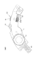
図1は交換レンズ鏡筒内のフォーカス駆動機構を示す断面図、図2,図3はそれぞれ図1のA方向,B方向から見た図である。フォーカス駆動機構は、図1の右側よりMF伝達機構10、フリクションギア機構20、レンズ駆動機構30、AFモータ伝達機構40に大別される。MFおよびAFの駆動力はレンズ駆動機構30に伝達され、レンズ駆動機構30を介して不図示のフォーカス光学系を光軸方向に移動させる。また、不図示のマニュアル操作環の操作の有無を検出するMF操作検出機構50は、MF伝達機構10内に設けられる。
An embodiment of the present invention will be described with reference to FIGS.
FIG. 1 is a cross-sectional view showing a focus drive mechanism in an interchangeable lens barrel, and FIGS. 2 and 3 are views seen from directions A and B in FIG. 1, respectively. The focus drive mechanism is roughly divided into an
以下、各部の詳細を説明する。
<MF伝達機構,MF操作検出機構>
マニュアル操作環は、鏡筒の外周面に沿って光軸回りに回転操作可能とされ、その内周面に形成されたギアがMF連結ギア11と噛み合っている。MF連結ギア11は、軸部材12に対して回転不能に取り付けられ、軸部材12はギア上板1およびギア地板2に回転可能に軸支される。また軸部材12の図示下部にはフランジ12aが形成され、そのフランジ12aにMF操作検出機構50を構成するガラスエポキシ基板51が固着されている。したがって、マニュアル操作環の回転操作(MF操作)がなされると、MF連結ギア11、軸部材12およびガラスエポキシ基板51が一体に回転する。
Details of each part will be described below.
<MF transmission mechanism, MF operation detection mechanism>
The manual operation ring can be rotated around the optical axis along the outer peripheral surface of the lens barrel, and a gear formed on the inner peripheral surface meshes with the
ガラスエポキシ基板51は、フランジ12aとほぼ同径の円盤状とされ、フランジ12aに両面テープで貼り付けられている。基板51の表面に形成されたパターンは、図2に示すように回転中心側が全導通パターン51a、その外側が放射状のパターン51bとされる。モータ上板1に取り付けられたブラシ52は、パターン51a,51bにそれぞれ接触しており、ブラシ52とパターン51a,51bとから成るスイッチの信号が不図示の制御部に入力される。基板51が回転すると、スイッチのオン信号およびオフ信号が交互に入力されるので、制御部はマニュアル操作環が回転操作されたことを認識できる。
The
軸部材12に回転可能に軸支されたクラッチギア14は、フリクションギア21と噛み合い、またフランジ12aとの間に設けたばね15、およびMF連結ギア11と連動するワッシャ16を介してMF連結ギア11に押し付けられる。通常は、クラッチギア14はMF連結ギア11と一体に回転してフリクションギア21に回転を伝達するが、フリクションギア21の回転負荷が所定値以上になると、クラッチギア14は静止したままMF連結ギア11および軸部材12が回転する。このクラッチギア14を設けることで、フォーカス光学系が至近側、無限遠側のいずれかの端部に達して移動が阻止されても、マニュアル操作環の回転(空回り)が許容されるため、各部に無理な力が加わることがなくその破損を防止できる。
なお17は、上述した軸部材12上の各部品を締結するためのE型止め輪である。
The clutch gear 14 rotatably supported by the
<フリクションギア機構>
フリクションギア21は、ばね摺動部21aを有し、フリクションばね22に押し付けられた状態でギア上板1に回転可能に軸支される。フリクションギア21を回転させるには、フリクションばね22のばね力により発生するトルクに打ち勝つだけのトルクを必要とし、そのトルクを生ぜしめるだけの力量でマニュアル操作環を操作することにより適度な操作環を与えている。
<Friction gear mechanism>
The
<レンズ駆動機構>
フリクションギア21は、軸部材31に回転不能に取り付けられたMF入力ギア32に噛み合っている。軸部材31はギア上板1およびギア地板2に回転可能に軸支され、その上部には太陽ギア31aが一体に形成されている。フリクションギア21の回転は、MF入力ギア32を介して軸部材31を回転させ、これに伴って太陽ギア31aが回転する。
<Lens drive mechanism>
The
33は軸部材31に回転可能に軸支されたギア部材であり、外周面および内周面にそれぞれ外側ギア33a、内側ギア33bを有する。内側ギア33aは、太陽ギア31aを囲むように位置する。軸部材31には、フォーカス光学系に動力を伝達するキャリアギア34が回転可能に軸支され、キャリアギア34に回転可能に軸支された複数の遊星ギア35が太陽ギア31aと内側ギア33aとに噛み合っている。複数の遊星ギア35は、キャリアギア34の回転軸(軸部材31の回転中心)から等距離に配置されており、遊星ギア35がキャリアギアの回転軸回りに公転することで、キャリアギア34が回転する。36は遊星ギア35の抜け止め用ワッシャである。
Reference numeral 33 denotes a gear member rotatably supported by the
<AFモータ伝達機構>
フォーカスモータ41は、レンズ光軸と平行な軸回りに回転する小型の振動波モータであり、その出力軸に設けられたギア42が上記ギア部材33の外側ギア33aに噛み合っている。モータ41には、配線部材43(図2,図3)を介して駆動信号が入力される。
<AF motor transmission mechanism>
The
以上の構成において、AFモードのときにAF開始操作を行うと、カメラの制御部はAF動作を行うべくフォーカスモータ41を駆動する。モータ41の回転は、ギア42および外側ギア33aを介してギア部材33を回転させ、これに伴って複数の遊星ギア35が回転する。一方、軸部材31は、フリクションギア21とMF入力ギア32との噛み合いによりロックされている(フリクションギア21を回転させるだけのトルクが伝達されない)ので、太陽ギア31aは回転しない。したがって、遊星ギア35は回転しながら軸部材31の中心軸回りに公転し、その公転がキャリアギア34を回転させる。キャリアギア34の回転により、不図示のフォーカス光学系が光軸方向に移動する(AFが行われる)。このとき、フリクションギア21が回転しないため、MF伝達機構10やマニュアル操作環が回転することはない。
In the above configuration, when an AF start operation is performed in the AF mode, the control unit of the camera drives the
MFモードに切換えることなくMF操作(マニュアル操作環の操作)を行うと、上述した回転検出機構50がその回転を検出し、制御部はフォーカスモータ41を停止する。マニュアル操作環の回転力は、クラッチギア14を介してフリクションギア21を回転させ、ギア32を介して軸部材31、すなわち太陽ギア31aを回転させる。一方、ギア部材33はギア42によりロックされているため回転せず、遊星ギア35は回転しながら軸部材31の中心軸回りに公転する。これにより上述と同様にキャリアギア34が回転し、フォーカス光学系が駆動される(MFが行われる)。MF操作終了後にAFを行うには、単にAF開始操作を行うだけでよい。
When an MF operation (manual operation ring operation) is performed without switching to the MF mode, the
以上のように本実施形態では、MF操作検出用のガラスエポキシ基板41を、マニュアル操作環ではなく、マニュアル操作環に連動するギア軸に一体に設けた。したがって、マニュアル操作環に固着されるような大径の円環状のガラスエポキシ基板とする必要はなく、小径の円盤状のガラスエポキシ基板で済み、製造工程におけるロスを小さくでき、コストダウンが図れる。
As described above, in the present embodiment, the
ところで、上述したようにクラッチギア14の作用により、フォーカス光学系が駆動端に達してもマニュアル操作環を空回りさせることができる。一方、マニュアル操作環の回転検出は、クラッチの状態(接続・遮断)に拘わらずなされる必要があるため、ガラスエポキシ基板51は、動力伝達経路においてクラッチギア14よりも前段に設ける必要がある。仮にクラッチギア41の後段にガラスエポキシ基板51を設けると、マニュアル操作環が空回りしているときには回転検出がなされず、MF操作継続中であるにも拘わらずフォーカスモータが駆動されてしまうおそれがある。例えば、フォーカス光学系が駆動端である最至近位置に達した後も至近方向のMF操作が継続されたとする。このとき、モータが逆方向に駆動されると、フォーカス光学系がMF操作方向とは逆の無限遠側に移動してしまい、撮影者は大きな不信感を抱く。本実施形態では、ガラスエポキシ基板51が軸部材12と一体の部材、つまりクラッチギア14の前段に取り付けられているので、上記のような不都合は生じ得ない。
By the way, as described above, the manual operation ring can be idled by the action of the clutch gear 14 even when the focus optical system reaches the drive end. On the other hand, since the rotation of the manual operation ring needs to be detected regardless of the state of the clutch (connected / disconnected), the
なお、MF伝達機構10において、クラッチギアの前段に複数の回転部材(ギア、ギア軸など)がある場合には、そのいずれの回転部材にガラスエポキシ基板を設けてもよい。ただし、なるべくマニュアル操作環に近い回転部材に設けた方が検出精度は高い。図1の例ではマニュアル操作環の次段の回転部材にガラスエポキシ基板を設けているので、精度的には最も高い。また、クラッチは発明の必須要件ではなく、クラッチなしの場合には、マニュアル操作環の操作に連動する回転部材のいずれにガラスエポキシ基板を設けてもよい。図1の例でクラッチギア14を廃止したとすると、ガラスエポキシ基板をギア21や軸部材31などに設けてもよい。さらにフォーカス駆動機構について説明したが、マニュアルおよび電動のズームが可能な交換レンズであれば、そのズーム駆動機構にも本発明を適用できる。
In the
10 MF伝達機構
11 MF連結ギア
12 軸部材
14 クラッチギア
20 フリクションギア機構
30 レンズ駆動機構
40 AFモータ伝達機構
41 モータ
50 MF操作検出機構
51 ガラスエポキシ基板
52 ブラシ
DESCRIPTION OF
Claims (7)
前記第1の動力伝達機構は、レンズが駆動端に達してその移動が阻止された後も前記マニュアル操作環の空回りを許容するためのクラッチ機構を有し、
前記操作検出手段は、前記第1の動力伝達機構の動力伝達経路中の、前記マニュアル操作環とクラッチ機構との間に設けられた回転部材に形成されたパターン部と、該パターン部の回転の有無に応じた信号を出力する信号出力手段とから構成されることを特徴とするカメラ用交換レンズ。 A manual operation ring that can be rotated around the optical axis, a first power transmission mechanism that transmits the rotation of the manual operation ring to the lens driving member, an operation detection means that detects the operation of the manual operation ring, and a motor A camera comprising: a second power transmission mechanism that transmits a driving force to the lens driving member; and a control unit that stops the rotation of the motor when an operation of the manual operation ring is detected by the operation detection unit. For interchangeable lenses,
The first power transmission mechanism has a clutch mechanism for allowing the manual operation ring to idle even after the lens reaches the driving end and its movement is blocked,
The operation detecting means includes a pattern portion formed on a rotating member provided between the manual operation ring and the clutch mechanism in the power transmission path of the first power transmission mechanism, and rotation of the pattern portion. An interchangeable lens for a camera, comprising: signal output means for outputting a signal according to presence or absence.
前記第1の動力伝達機構は、前記マニュアル操作環に設けられたギアと噛み合う連結ギアを有し、
前記操作検出手段は、前記連結ギアと一体に回転する回転部材に形成されたパターン部と、該パターン部の回転の有無に応じた信号を出力する信号出力手段とから構成されることを特徴とするカメラ用交換レンズ。 A manual operation ring that can be rotated around the optical axis, a first power transmission mechanism that transmits the rotation of the manual operation ring to the lens driving member, an operation detection means that detects the operation of the manual operation ring, and a motor A camera comprising: a second power transmission mechanism that transmits a driving force to the lens driving member; and a control unit that stops the rotation of the motor when an operation of the manual operation ring is detected by the operation detection unit. For interchangeable lenses,
The first power transmission mechanism has a connection gear that meshes with a gear provided in the manual operation ring,
The operation detection means includes a pattern portion formed on a rotating member that rotates integrally with the connection gear, and a signal output means that outputs a signal corresponding to the presence or absence of rotation of the pattern portion. interchangeable camera lens.
Priority Applications (1)
| Application Number | Priority Date | Filing Date | Title |
|---|---|---|---|
| JP2005257696A JP4784214B2 (en) | 2005-09-06 | 2005-09-06 | Interchangeable lens for camera |
Applications Claiming Priority (1)
| Application Number | Priority Date | Filing Date | Title |
|---|---|---|---|
| JP2005257696A JP4784214B2 (en) | 2005-09-06 | 2005-09-06 | Interchangeable lens for camera |
Publications (3)
| Publication Number | Publication Date |
|---|---|
| JP2007072077A JP2007072077A (en) | 2007-03-22 |
| JP2007072077A5 JP2007072077A5 (en) | 2008-10-16 |
| JP4784214B2 true JP4784214B2 (en) | 2011-10-05 |
Family
ID=37933585
Family Applications (1)
| Application Number | Title | Priority Date | Filing Date |
|---|---|---|---|
| JP2005257696A Expired - Fee Related JP4784214B2 (en) | 2005-09-06 | 2005-09-06 | Interchangeable lens for camera |
Country Status (1)
| Country | Link |
|---|---|
| JP (1) | JP4784214B2 (en) |
Families Citing this family (2)
| Publication number | Priority date | Publication date | Assignee | Title |
|---|---|---|---|---|
| JP2016148688A (en) | 2013-05-30 | 2016-08-18 | 株式会社 ニコンビジョン | Optical instrument |
| JP5774760B2 (en) * | 2014-11-05 | 2015-09-09 | 株式会社アイカムス・ラボ | Lens focus mechanism |
Family Cites Families (4)
| Publication number | Priority date | Publication date | Assignee | Title |
|---|---|---|---|---|
| JP2602281B2 (en) * | 1988-04-18 | 1997-04-23 | 株式会社日立製作所 | Automatic focusing device |
| JP3450345B2 (en) * | 1992-03-16 | 2003-09-22 | キヤノン株式会社 | Driving force transmission device and lens barrel |
| JP3243019B2 (en) * | 1992-12-09 | 2002-01-07 | 富士写真光機株式会社 | Lens initial position detection device |
| JPH085894A (en) * | 1994-06-22 | 1996-01-12 | Nikon Corp | Lens barrel |
-
2005
- 2005-09-06 JP JP2005257696A patent/JP4784214B2/en not_active Expired - Fee Related
Also Published As
| Publication number | Publication date |
|---|---|
| JP2007072077A (en) | 2007-03-22 |
Similar Documents
| Publication | Publication Date | Title |
|---|---|---|
| EP2270358B1 (en) | One-way transmission for motor | |
| JP2012117661A (en) | Shift operation mechanism for manual transmission | |
| WO2012111165A1 (en) | Clutch switching device and twin clutch-type transmission comprising clutch switching device | |
| JP4784214B2 (en) | Interchangeable lens for camera | |
| JP2003205756A (en) | Drive unit for hybrid vehicle | |
| US9097960B2 (en) | Lens barrel and camera system | |
| US4575210A (en) | Automatic focusing device | |
| JP2007085544A (en) | Parking brake for vehicle equipped with automatic lock device | |
| JP3841102B2 (en) | Hybrid vehicle drive device | |
| WO2009151122A1 (en) | Power transmitting device | |
| US7864462B2 (en) | Interchangeable lens incorporating a lens drive motor | |
| JP2019168007A (en) | Engagement device | |
| JP2011179547A (en) | Continuously variable transmission and actuator | |
| JP4590190B2 (en) | Optical equipment | |
| JP4943036B2 (en) | Driving device used in image forming apparatus | |
| JP2007072077A5 (en) | ||
| JP4710527B2 (en) | Drive mechanism and device provided with drive mechanism | |
| JPH02137811A (en) | Lens barrel | |
| JP2004125140A (en) | Clutch | |
| JP4953985B2 (en) | Lens device | |
| JPH02253212A (en) | Lens barrel | |
| JP5285006B2 (en) | Lens drive device | |
| JP2000179635A (en) | Driving force transmission device, driving device and optical equipment | |
| JP2002040314A (en) | Driving mechanism for lens barrel | |
| WO2010090140A1 (en) | Power transmission device |
Legal Events
| Date | Code | Title | Description |
|---|---|---|---|
| A621 | Written request for application examination |
Free format text: JAPANESE INTERMEDIATE CODE: A621 Effective date: 20080820 |
|
| A521 | Request for written amendment filed |
Free format text: JAPANESE INTERMEDIATE CODE: A523 Effective date: 20080828 |
|
| RD02 | Notification of acceptance of power of attorney |
Free format text: JAPANESE INTERMEDIATE CODE: A7422 Effective date: 20080828 |
|
| A977 | Report on retrieval |
Free format text: JAPANESE INTERMEDIATE CODE: A971007 Effective date: 20110120 |
|
| A131 | Notification of reasons for refusal |
Free format text: JAPANESE INTERMEDIATE CODE: A131 Effective date: 20110208 |
|
| A521 | Request for written amendment filed |
Free format text: JAPANESE INTERMEDIATE CODE: A523 Effective date: 20110411 |
|
| TRDD | Decision of grant or rejection written | ||
| A01 | Written decision to grant a patent or to grant a registration (utility model) |
Free format text: JAPANESE INTERMEDIATE CODE: A01 Effective date: 20110614 |
|
| A01 | Written decision to grant a patent or to grant a registration (utility model) |
Free format text: JAPANESE INTERMEDIATE CODE: A01 |
|
| A61 | First payment of annual fees (during grant procedure) |
Free format text: JAPANESE INTERMEDIATE CODE: A61 Effective date: 20110627 |
|
| R150 | Certificate of patent or registration of utility model |
Ref document number: 4784214 Country of ref document: JP Free format text: JAPANESE INTERMEDIATE CODE: R150 Free format text: JAPANESE INTERMEDIATE CODE: R150 |
|
| FPAY | Renewal fee payment (event date is renewal date of database) |
Free format text: PAYMENT UNTIL: 20140722 Year of fee payment: 3 |
|
| FPAY | Renewal fee payment (event date is renewal date of database) |
Free format text: PAYMENT UNTIL: 20140722 Year of fee payment: 3 |
|
| R250 | Receipt of annual fees |
Free format text: JAPANESE INTERMEDIATE CODE: R250 |
|
| R250 | Receipt of annual fees |
Free format text: JAPANESE INTERMEDIATE CODE: R250 |
|
| R250 | Receipt of annual fees |
Free format text: JAPANESE INTERMEDIATE CODE: R250 |
|
| R250 | Receipt of annual fees |
Free format text: JAPANESE INTERMEDIATE CODE: R250 |
|
| R250 | Receipt of annual fees |
Free format text: JAPANESE INTERMEDIATE CODE: R250 |
|
| R250 | Receipt of annual fees |
Free format text: JAPANESE INTERMEDIATE CODE: R250 |
|
| R250 | Receipt of annual fees |
Free format text: JAPANESE INTERMEDIATE CODE: R250 |
|
| LAPS | Cancellation because of no payment of annual fees |