JP4784115B2 - Radome - Google Patents
Radome Download PDFInfo
- Publication number
- JP4784115B2 JP4784115B2 JP2005072584A JP2005072584A JP4784115B2 JP 4784115 B2 JP4784115 B2 JP 4784115B2 JP 2005072584 A JP2005072584 A JP 2005072584A JP 2005072584 A JP2005072584 A JP 2005072584A JP 4784115 B2 JP4784115 B2 JP 4784115B2
- Authority
- JP
- Japan
- Prior art keywords
- frequency
- antenna
- layer
- radome
- dielectric layer
- Prior art date
- Legal status (The legal status is an assumption and is not a legal conclusion. Google has not performed a legal analysis and makes no representation as to the accuracy of the status listed.)
- Expired - Fee Related
Links
- 239000004020 conductor Substances 0.000 claims description 9
- 230000005540 biological transmission Effects 0.000 description 14
- 238000001514 detection method Methods 0.000 description 4
- 238000002834 transmittance Methods 0.000 description 3
- 230000002238 attenuated effect Effects 0.000 description 2
- 230000001747 exhibiting effect Effects 0.000 description 2
- 239000003973 paint Substances 0.000 description 2
- OKTJSMMVPCPJKN-UHFFFAOYSA-N Carbon Chemical compound [C] OKTJSMMVPCPJKN-UHFFFAOYSA-N 0.000 description 1
- RYGMFSIKBFXOCR-UHFFFAOYSA-N Copper Chemical compound [Cu] RYGMFSIKBFXOCR-UHFFFAOYSA-N 0.000 description 1
- 229910052799 carbon Inorganic materials 0.000 description 1
- 239000011889 copper foil Substances 0.000 description 1
- 239000011521 glass Substances 0.000 description 1
- 230000001771 impaired effect Effects 0.000 description 1
- 238000010030 laminating Methods 0.000 description 1
- 238000004519 manufacturing process Methods 0.000 description 1
- 239000002923 metal particle Substances 0.000 description 1
- 238000000034 method Methods 0.000 description 1
- 239000002245 particle Substances 0.000 description 1
- 239000012783 reinforcing fiber Substances 0.000 description 1
Images


Description
本発明は、レドームに関し、さらに詳しくは必要な周波数帯域の電波を透過させつつ、優れた遮蔽性能を発揮して被探知性能の向上を可能とするレドームに関するものである。 The present invention relates to a radome, and more particularly to a radome that can improve detection performance by exhibiting excellent shielding performance while transmitting radio waves in a necessary frequency band.
従来から、航空機、船舶、車両、建造物等に設置されるレーダアンテナを覆って、外部環境から保護するとともに、レーダアンテナが送受信する電波を透過可能とするレドームが使用されている。 Conventionally, a radome that covers a radar antenna installed in an aircraft, a ship, a vehicle, a building, and the like to protect it from the external environment and to transmit radio waves transmitted and received by the radar antenna has been used.
レドームが透過させる電波の周波数帯域が広域になると、第三者等が発信した電波も透過させ易くなり、透過した電波がレドームの内側に設置したレーダアンテナ等の設備で反射するため、第三者等にその存在を探知されてしまうことになる。 If the frequency band of the radio wave transmitted by the radome becomes wide, it will be easier to transmit the radio wave transmitted by a third party, and the transmitted radio wave will be reflected by equipment such as a radar antenna installed inside the radome. The existence will be detected.
そこで、レドームに周波数選択板(FSS)を設けて、透過させる周波数帯域を制限し、自己のレーダアンテナを従来どおり機能させつつ、第三者等の送信した電波の透過を防いでレーダ断面積(RCS)を減少させる構造が提案されている(特許文献1参照)。 Therefore, a frequency selection plate (FSS) is provided on the radome to limit the frequency band to be transmitted, while preventing the transmission of radio waves transmitted by a third party or the like while allowing its own radar antenna to function as before. A structure for reducing RCS) has been proposed (see Patent Document 1).
レドームで覆われるレーダアンテナは、多数の周波数帯域の電波を送受信することが多く、例えば、波長が10倍以上異なる電波が送受信されることもある。 Radar antennas covered with radomes often transmit and receive radio waves in a large number of frequency bands. For example, radio waves having wavelengths different by 10 times or more may be transmitted and received.
一般的に周波数選択板は、設定した透過周波数の逓倍波に対しても一定の透過率を有するので、レドームの内側に多数の周波数帯域の電波を送受信するレーダアンテナが設置され、低周波帯域の電波が透過可能な設定にすると、この逓倍波に相当する不要な電波の透過窓が形成されることになる。したがって、特許文献1で提案されている構造では、この不要な電波の透過窓から第三者等の発信した電波が透過および反射して遮蔽性が低下することになる。即ち、探知され易くなるという問題があった。
本発明の目的は、必要な周波数帯の電波を透過させつつ、優れた遮蔽性能を発揮して被探知性能の向上を可能とするレドームを提供することにある。 An object of the present invention is to provide a radome capable of improving detection performance by exhibiting excellent shielding performance while transmitting radio waves in a necessary frequency band.
上記目的を達成するため本発明のレドームは、レーダアンテナを周波数選択層を備えた壁体で覆い、前記レーダアンテナが送受信する所定の周波数帯域の電波を透過可能とするレドームであって、前記壁体の周波数選択層の外側に、前記レーダアンテナで使用される周波数帯域よりも低い帯域の周波数100MHz以上5GHz以下用の低周波アンテナを設け、前記周波数選択層は前記低周波アンテナで送受信する低周波帯域の電波を透過させないように設定したことを特徴とするものである。 In order to achieve the above object, a radome according to the present invention is a radome that covers a radar antenna with a wall body having a frequency selection layer and allows transmission of radio waves in a predetermined frequency band transmitted and received by the radar antenna. A low frequency antenna for a frequency of 100 MHz or more and 5 GHz or less in a band lower than a frequency band used by the radar antenna is provided outside a frequency selection layer of the body, and the frequency selection layer transmits and receives with the low frequency antenna. It is characterized in that it is set so as not to transmit radio waves in the band .
即ち、本発明において低周波とは、一般にレーダで使用されるX帯(8GHz〜12.5GHz)より低い帯域の100MHz以上5GHz以下の周波数を意味する。 That is , in the present invention, the low frequency means a frequency of 100 MHz or more and 5 GHz or less in a band lower than the X band (8 GHz to 12.5 GHz) generally used in radar.
本発明のレドームによれば、レーダアンテナを周波数選択層を備えた壁体で覆い、レーダアンテナが送受信する所定の周波数帯域の電波を透過可能とするレドームであって、壁体の周波数選択層の外側に、前記レーダアンテナで使用される周波数帯域よりも低い帯域の周波数100MHz以上5GHz以下用の低周波アンテナを設け、前記周波数選択層は前記低周波アンテナで送受信する低周波帯域の電波を透過させないように設定したので、第三者等が発信した不要な電波は、周波数選択層によって減衰して反射が抑制され、これによってレーダ断面積が減少するので優れた遮蔽性が発揮され、存在を探知されにくくすることが可能となる。一方で、必要な所定の周波数帯域の電波は周波数選択層を透過させて、レーダアンテナを通常どおりに機能させることができる。 According to the radome of the present invention, the radar antenna is covered with a wall body having a frequency selection layer, and is capable of transmitting radio waves in a predetermined frequency band transmitted and received by the radar antenna. A low frequency antenna having a frequency of 100 MHz or more and 5 GHz or less in a frequency band lower than that used by the radar antenna is provided outside, and the frequency selection layer does not transmit a radio wave in a low frequency band transmitted and received by the low frequency antenna. since the set as unnecessary radio waves third parties or the like originated is suppressed reflected attenuated by frequency selective layer, whereby the radar cross section is exhibited excellent shielding property due to the reduced, detect the presence It becomes possible to make it difficult to be done. On the other hand, radio waves in a required predetermined frequency band can be transmitted through the frequency selection layer, and the radar antenna can function normally.
また、必要な低周波帯域の電波は、低周波アンテナで送受信することができるので、周波数選択層を低周波帯域の電波を透過させるように設定する必要がない。そのため、周波数選択層に不要な電波の透過窓が形成されることがなく、第三者等の発信した電波の透過および反射を防いで、被探知性能を向上させることが可能となる。 In addition, since the necessary low frequency band radio waves can be transmitted and received by the low frequency antenna, it is not necessary to set the frequency selection layer to transmit the low frequency band radio waves. Therefore, an unnecessary radio wave transmission window is not formed in the frequency selection layer, and transmission and reflection of radio waves transmitted by a third party or the like can be prevented and detection performance can be improved.
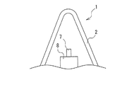
以下、本発明のレドームを図に示した実施形態に基づいて説明する。図3に示すように、レーダアンテナ7やレーダ装置8等は、レドーム1の壁体2に覆われて外部環境から保護されている。この壁体2は、レーダアンテナ7が送受信する所定の周波数帯域の電波が透過可能となっている。
Hereinafter, the radome of the present invention will be described based on the embodiments shown in the drawings. As shown in FIG. 3, the
この壁体2の構造を図1および図2に示す。厚み方向の断面構造は、図1に示すように内側から順に第1誘電体層4a、周波数選択層3、第2誘電体層4b、第3誘電体層4cが積層されている。第2誘電体層4bと第3誘電体層4cとの間には導体5が配置されている。
The structure of the
図2は、この壁体2の内部構造を誘電体層4を透視して正面で示したものであり、多数の十字状の開口部3aを所定周期で配置した周波数選択層3が用いられており、周波数選択層3の正面方向に対して、中央部下側に小型の矩形板状の導体5が配置されている。
FIG. 2 is a front view showing the internal structure of the
周波数選択層3は、例えば、金属粒子やカーボン粒子等を混入させた導電性塗料を塗工することや、プリント基板の製造工程を用いて銅箔等によって形成され、透過させる周波数帯域によって、開口部3aの大きさ、形状、配置周期が適宜、決定される。したがって、開口部3aの形状は図示したものに限定されないが、遮蔽性を向上させるには、いわゆる開口型の周波数選択層3が好ましい。
The frequency
上記した壁体2の構造において、第2誘電体層4bと、第2誘電体層4bを挟んで対向する周波数選択層3および導体5とによって、周波数選択層3をグランド面として利用したマイクロストリップアンテナ6が構成される。
In the structure of the
周波数選択層3の外側に設けるアンテナは、このようなマイクロストリップアンテナ6に限定されず、他のタイプの低周波アンテナを用いることができるが、マイクロストリップアンテナ6にするとレドーム1の壁体2に実装し易くなる。
The antenna provided outside the
この構造によれば、図1に示すようにレドーム1の内側に設置されたレーダアンテナ7が送受信する所定の周波数帯域の電波HWは、壁体2を透過するのでレーダアンテナ7は所定どおりに機能する。一方、必要な低周波帯域の電波LWは、マイクロストリップアンテナ6によって送受信されることになり、多数の周波数帯域の電波を送受信することが可能となる。
According to this structure, as shown in FIG. 1, the radio wave HW of a predetermined frequency band transmitted and received by the
第三者等が送信した外部からの不要な電波EWは、周波数選択層3によって減衰して壁体2を透過しにくくなり、内側のレーダアンテナ7やレーダ装置8等による反射が抑制されて、第三者等がその反射波を受信するのは困難となる。このように優れた遮蔽性が発揮されて、レーダ断面積(RCS)が減少して存在の探知がされにくくなる。
Unnecessary external radio waves EW transmitted by a third party or the like are attenuated by the
図4に1.0GHzおよび9.5GHzの周波数の電波の送受信が必要とされる場合の周波数選択層3の電波透過特性を例示する。図4の縦軸は電波の透過率、横軸は周波数を示している。
FIG. 4 illustrates the radio wave transmission characteristics of the
低周波アンテナ6を周波数選択層3の外側に設けず、レドーム1の内側に設置する従来のようなレドームでは、周波数選択層3は1.0GHzおよび9.5GHzの周波数の電波を透過させるように設定されることになる。
In a conventional radome where the low-
一般に周波数選択層3は、透過可能に設定した周波数の電波だけでなく、その逓倍波に対しても一定の透過率を有するようになる。したがって、周波数選択層3の電波透過特性は、図4の曲線Hおよび曲線Lで示すものとなり、曲線Lが示すように設定周波数(1GHz)だけでなく、その逓倍波となる2GHz、3GHz、4GHz等の周波数においても透過のピークを有することになる。このように、不要な電波の透過窓が形成されて遮蔽性が損なわれることになる。
In general, the
実施形態では、1.0GHzの低周波の電波はマイクロストリップアンテナ6で送受信されるため、周波数選択層3は、9.5GHzの周波数の電波のみを透過されるように設定され、周波数選択層3は曲線Hで示すような電波透過特性となる。
In the embodiment, since the low frequency radio wave of 1.0 GHz is transmitted / received by the
即ち、周波数選択層3の外側に設けたマイクロストリップアンテナ6の存在によって、曲線Lで示した電波の透過窓が形成されずに優れた遮蔽性を発揮して、被探知性能を向上させることが可能となる。
That is, the presence of the
尚、実施形態では、第1誘電体層4a〜第3誘電体層4cを設けているが、誘電体層4は透過させる電波の周波数、透過率、機械的強度等によって、厚み、積層数、誘電率等が適宜、決定され、実施形態に示したものに限定されるものではない。
In the embodiment, the first
例えば、図1において第3誘電体層4cを単なる一般的な塗装面にすることもできる。また、図5(a)に示すように誘電体層4を第1誘電体層4aと第2誘電体層4bとの2層構造にすることも、図5(b)に示すように第1誘電体層4a〜第4誘電体層4dを設けて4層構造にして、第1誘電体層4aと第2誘電体層4bとの間、第2誘電体層4bと第3誘電体層4cとの間に周波数選択層3をそれぞれ設ける構造にすることもできる。
For example, the third
本発明で用いられる低周波アンテナの実装性を確認するため、3つのタイプのアンテナをモデル解析して整合状態を評価した。モデルの断面構造は、図5(a)で示す構造として、導体5を挟む一方面の誘電体層4aを厚さ4mm、比誘電率(ε)4.5、誘電正接(tanδ)0.008のガラス強化繊維プラスチック(GFRP)、他方面の誘電体層4bを一般的な塗装の塗膜層とし、グランド面となる周波数選択層3を高周波用開口型FSS層としたことを共通の条件として、導体5の仕様を表1および図6(a)〜(c)に示す3タイプとした。尚、図6(a)〜(c)において、符号Sが同軸の給電部である。表1のフィード位置とは導体(マイクロストリップパッチ)5の図中左縁から給電部Sまでの距離Fを意味する。
In order to confirm the mountability of the low-frequency antenna used in the present invention, three types of antennas were model-analyzed to evaluate the matching state. The cross-sectional structure of the model is the structure shown in FIG. 5A, in which the

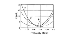
モーメント法を用いて解析し、定在波比(VSWR)を求めた結果を図7に示す。図7の縦軸は電圧定在波比(VSWR)、横軸は周波数を示している。この結果から、すべての実施例が、目的としたIFF帯(1.03〜1.09GHz)においてVSWR値が1に近く、良好な整合状態となり、使用可能な形態であることが解る。実際の用途において、帯域幅、指向性の点で改善するには導体5の素子形状の工夫とアレイ化によって対応することができる。
FIG. 7 shows the result of analysis using the method of moments to obtain the standing wave ratio (VSWR). In FIG. 7, the vertical axis represents the voltage standing wave ratio (VSWR), and the horizontal axis represents the frequency. From this result, it can be seen that all the examples are in a usable state in which the VSWR value is close to 1 in the intended IFF band (1.03 to 1.09 GHz), a good matching state is obtained. In actual applications, improvement in bandwidth and directivity can be dealt with by devising the element shape of the
1 レドーム 2 壁体
3 周波数選択層(FSS) 3a 開口部
4 誘電体層
4a 第1誘電体層 4b 第2誘電体層
4c 第3誘電体層 4d 第4誘電体層
5 導体
6 低周波アンテナ(マイクロストリップアンテナ)
7 レーダアンテナ 8 レーダ装置
1
4a 1st
7
Claims (2)
Priority Applications (1)
| Application Number | Priority Date | Filing Date | Title |
|---|---|---|---|
| JP2005072584A JP4784115B2 (en) | 2005-03-15 | 2005-03-15 | Radome |
Applications Claiming Priority (1)
| Application Number | Priority Date | Filing Date | Title |
|---|---|---|---|
| JP2005072584A JP4784115B2 (en) | 2005-03-15 | 2005-03-15 | Radome |
Publications (2)
| Publication Number | Publication Date |
|---|---|
| JP2006258449A JP2006258449A (en) | 2006-09-28 |
| JP4784115B2 true JP4784115B2 (en) | 2011-10-05 |
Family
ID=37097897
Family Applications (1)
| Application Number | Title | Priority Date | Filing Date |
|---|---|---|---|
| JP2005072584A Expired - Fee Related JP4784115B2 (en) | 2005-03-15 | 2005-03-15 | Radome |
Country Status (1)
| Country | Link |
|---|---|
| JP (1) | JP4784115B2 (en) |
Cited By (2)
| Publication number | Priority date | Publication date | Assignee | Title |
|---|---|---|---|---|
| CN102800960A (en) * | 2012-07-23 | 2012-11-28 | 中国科学院长春光学精密机械与物理研究所 | Antenna cover for reducing transmission loss and inserting phase displacement |
| CN102882002A (en) * | 2012-09-27 | 2013-01-16 | 中国科学院长春光学精密机械与物理研究所 | Composite frequency-selective-surface invisible radome |
Families Citing this family (9)
| Publication number | Priority date | Publication date | Assignee | Title |
|---|---|---|---|---|
| WO2009137124A2 (en) * | 2008-02-07 | 2009-11-12 | The Penn State Research Foundation | Methods and apparatus for reduced coupling and interference between antennas |
| KR101173883B1 (en) | 2010-12-30 | 2012-08-16 | 국방과학연구소 | Radom structure |
| JP6142522B2 (en) * | 2012-12-20 | 2017-06-07 | 横浜ゴム株式会社 | Frequency selection member and method for determining frequency selection element arrangement on curved surface |
| JP6363528B2 (en) | 2015-02-09 | 2018-07-25 | 株式会社デンソー | Radar device mounting structure |
| JP6410676B2 (en) * | 2015-06-25 | 2018-10-24 | 三菱電機株式会社 | Antenna device |
| CN106602252B (en) * | 2017-01-20 | 2023-09-01 | 浙江大学 | 2.5-dimensional ultra-wideband mobile communication radome with grid square ring loaded via hole structure |
| JP6908417B2 (en) * | 2017-04-11 | 2021-07-28 | 株式会社デンソー | Object detection method by in-vehicle radar device and in-vehicle radar system |
| CN108008361B (en) * | 2017-11-07 | 2021-05-25 | 南京航空航天大学 | Distributed MIMO radar interference waveform design method based on radio frequency stealth |
| JP7225650B2 (en) * | 2018-10-03 | 2023-02-21 | 横浜ゴム株式会社 | Frequency selection member and manufacturing method thereof |
Family Cites Families (7)
| Publication number | Priority date | Publication date | Assignee | Title |
|---|---|---|---|---|
| JP2516293Y2 (en) * | 1991-04-24 | 1996-11-06 | 三菱電機株式会社 | Array antenna device |
| IL105925A (en) * | 1992-06-22 | 1997-01-10 | Martin Marietta Corp | Ablative process for printed circuit board technology |
| SE504815C2 (en) * | 1995-08-17 | 1997-04-28 | Ericsson Telefon Ab L M | Protection for one or more electromagnetic sensors |
| JPH09257928A (en) * | 1996-03-18 | 1997-10-03 | Mitsubishi Electric Corp | Weather radar equipment |
| EA001583B1 (en) * | 1996-07-04 | 2001-06-25 | Скайгейт Интернэшнл Текнолоджи Н.В. | A planar dual-frequency arrey antenna |
| JP2001298322A (en) * | 2000-04-11 | 2001-10-26 | Sumitomo Electric Ind Ltd | Radome for aircraft |
| JP2004179730A (en) * | 2002-11-25 | 2004-06-24 | Yokohama Rubber Co Ltd:The | Joining structure of layered body in which frequency selecting element used for radome is incorporated |
-
2005
- 2005-03-15 JP JP2005072584A patent/JP4784115B2/en not_active Expired - Fee Related
Cited By (2)
| Publication number | Priority date | Publication date | Assignee | Title |
|---|---|---|---|---|
| CN102800960A (en) * | 2012-07-23 | 2012-11-28 | 中国科学院长春光学精密机械与物理研究所 | Antenna cover for reducing transmission loss and inserting phase displacement |
| CN102882002A (en) * | 2012-09-27 | 2013-01-16 | 中国科学院长春光学精密机械与物理研究所 | Composite frequency-selective-surface invisible radome |
Also Published As
| Publication number | Publication date |
|---|---|
| JP2006258449A (en) | 2006-09-28 |
Similar Documents
| Publication | Publication Date | Title |
|---|---|---|
| JP4784115B2 (en) | Radome | |
| US11005170B2 (en) | Millimeter-wave radar cover | |
| EP1635187B1 (en) | Millimeter wave radar with side-lobe absorbing radome | |
| US9553359B2 (en) | Antenna apparatus | |
| US4656487A (en) | Electromagnetic energy passive filter structure | |
| US8525741B2 (en) | Multi-loop antenna system and electronic apparatus having the same | |
| EP1764859A1 (en) | Glass antenna and manufacturing method for the same | |
| US8508413B2 (en) | Antenna with dielectric having geometric patterns | |
| US11374311B2 (en) | Millimeter-wave radar cover | |
| US10454180B2 (en) | Isolation barrier | |
| US10784574B2 (en) | Antenna | |
| KR102475582B1 (en) | Inverted Feeding Microstrip Ppatch Aantenna for vehicle radar | |
| US20170365920A1 (en) | Antenna device | |
| WO2012153663A1 (en) | Windshield-integrated antenna and glazing | |
| WO2018235593A1 (en) | Antenna device | |
| JP4788333B2 (en) | Glass antenna for vehicles | |
| JP2012122801A (en) | Antenna for radar, and radar device | |
| JP2019068355A (en) | Cover for millimeter wave radar | |
| US9640854B2 (en) | Wireless communication device | |
| JP2005244884A (en) | Laminated frequency selective plate, antenna dome and mast for warships | |
| US20200295467A1 (en) | Electromagnetic bandgap isolation systems and methods | |
| US11271326B2 (en) | Antenna system | |
| CN215497083U (en) | Millimeter wave radar metamaterial antenna housing and antenna system | |
| US20220416399A1 (en) | Vehicle pane | |
| CN220797087U (en) | Microstrip antenna |
Legal Events
| Date | Code | Title | Description |
|---|---|---|---|
| A621 | Written request for application examination |
Free format text: JAPANESE INTERMEDIATE CODE: A621 Effective date: 20080306 |
|
| A977 | Report on retrieval |
Free format text: JAPANESE INTERMEDIATE CODE: A971007 Effective date: 20100208 |
|
| A131 | Notification of reasons for refusal |
Free format text: JAPANESE INTERMEDIATE CODE: A131 Effective date: 20100216 |
|
| A521 | Request for written amendment filed |
Free format text: JAPANESE INTERMEDIATE CODE: A523 Effective date: 20100407 |
|
| A131 | Notification of reasons for refusal |
Free format text: JAPANESE INTERMEDIATE CODE: A131 Effective date: 20100629 |
|
| A521 | Request for written amendment filed |
Free format text: JAPANESE INTERMEDIATE CODE: A523 Effective date: 20100723 |
|
| TRDD | Decision of grant or rejection written | ||
| A01 | Written decision to grant a patent or to grant a registration (utility model) |
Free format text: JAPANESE INTERMEDIATE CODE: A01 Effective date: 20110614 |
|
| A01 | Written decision to grant a patent or to grant a registration (utility model) |
Free format text: JAPANESE INTERMEDIATE CODE: A01 |
|
| A61 | First payment of annual fees (during grant procedure) |
Free format text: JAPANESE INTERMEDIATE CODE: A61 Effective date: 20110627 |
|
| R150 | Certificate of patent or registration of utility model |
Ref document number: 4784115 Country of ref document: JP Free format text: JAPANESE INTERMEDIATE CODE: R150 Free format text: JAPANESE INTERMEDIATE CODE: R150 |
|
| FPAY | Renewal fee payment (event date is renewal date of database) |
Free format text: PAYMENT UNTIL: 20140722 Year of fee payment: 3 |
|
| FPAY | Renewal fee payment (event date is renewal date of database) |
Free format text: PAYMENT UNTIL: 20140722 Year of fee payment: 3 |
|
| R250 | Receipt of annual fees |
Free format text: JAPANESE INTERMEDIATE CODE: R250 |
|
| R250 | Receipt of annual fees |
Free format text: JAPANESE INTERMEDIATE CODE: R250 |
|
| R250 | Receipt of annual fees |
Free format text: JAPANESE INTERMEDIATE CODE: R250 |
|
| R250 | Receipt of annual fees |
Free format text: JAPANESE INTERMEDIATE CODE: R250 |
|
| R250 | Receipt of annual fees |
Free format text: JAPANESE INTERMEDIATE CODE: R250 |
|
| R250 | Receipt of annual fees |
Free format text: JAPANESE INTERMEDIATE CODE: R250 |
|
| R250 | Receipt of annual fees |
Free format text: JAPANESE INTERMEDIATE CODE: R250 |
|
| R250 | Receipt of annual fees |
Free format text: JAPANESE INTERMEDIATE CODE: R250 |
|
| R250 | Receipt of annual fees |
Free format text: JAPANESE INTERMEDIATE CODE: R250 |
|
| LAPS | Cancellation because of no payment of annual fees |