JP4783683B2 - Electrodynamic electroacoustic transducer and electronic equipment - Google Patents

Electrodynamic electroacoustic transducer and electronic equipment Download PDF

Info

Publication number
JP4783683B2
JP4783683B2 JP2006175737A JP2006175737A JP4783683B2 JP 4783683 B2 JP4783683 B2 JP 4783683B2 JP 2006175737 A JP2006175737 A JP 2006175737A JP 2006175737 A JP2006175737 A JP 2006175737A JP 4783683 B2 JP4783683 B2 JP 4783683B2
Authority
JP
Japan
Prior art keywords
magnetic pole
magnet
electroacoustic transducer
diaphragm
magnetic
Prior art date
Legal status (The legal status is an assumption and is not a legal conclusion. Google has not performed a legal analysis and makes no representation as to the accuracy of the status listed.)
Active
Application number
JP2006175737A
Other languages
Japanese (ja)
Other versions
JP2007104634A5 (en
JP2007104634A (en
Inventor
俊之 松村
周二 佐伯
佐和子 狩野
浩司 佐野
Current Assignee (The listed assignees may be inaccurate. Google has not performed a legal analysis and makes no representation or warranty as to the accuracy of the list.)
Panasonic Corp
Panasonic Holdings Corp
Original Assignee
Panasonic Corp
Matsushita Electric Industrial Co Ltd
Priority date (The priority date is an assumption and is not a legal conclusion. Google has not performed a legal analysis and makes no representation as to the accuracy of the date listed.)
Filing date
Publication date
Application filed by Panasonic Corp, Matsushita Electric Industrial Co Ltd filed Critical Panasonic Corp
Priority to JP2006175737A priority Critical patent/JP4783683B2/en
Publication of JP2007104634A publication Critical patent/JP2007104634A/en
Publication of JP2007104634A5 publication Critical patent/JP2007104634A5/ja
Application granted granted Critical
Publication of JP4783683B2 publication Critical patent/JP4783683B2/en
Active legal-status Critical Current
Anticipated expiration legal-status Critical

Links

Images

Description

本発明は、動電型電気音響変換器および電子機器に関し、より特定的には、携帯電話、PDA(Personal degital assistants)、テレビ、パーソナルコンピュータ、カーナビゲーション、およびポータブルプレーヤ等の電子機器に搭載され、音響信号を再生する動電型電気音響変換器と、それを搭載する電子機器に関する。   The present invention relates to an electrodynamic electroacoustic transducer and an electronic device, and more specifically, is mounted on an electronic device such as a mobile phone, a PDA (Personal Digital Assistants), a television, a personal computer, a car navigation, and a portable player. The present invention relates to an electrodynamic electroacoustic transducer that reproduces an acoustic signal and an electronic device on which it is mounted.

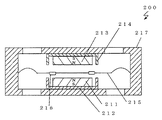
従来、携帯電話やPDAなどをはじめとした電子機器において、薄型化、低消費電力化が進んでいる。それに伴い、これらに搭載される電気音響変換器においても、より小型化、より高効率化が望まれている。電気音響変換器において高効率化するための最も一般的な手法は、マグネットの体積を増加させることである。しかし、マグネットの体積が増加すると、電気音響変換器自体の体積が大きくなってしまう。そこで、小型化および高効率化を実現するために、図3に示すような動電型電気音響変換器200が提案されている(例えば、特許文献1参照)。なお、図39は、従来における動電型電気音響変換器200の構造断面図である。 Conventionally, electronic devices such as mobile phones and PDAs have been reduced in thickness and power consumption. Along with that, electroacoustic transducers mounted on these devices are also desired to be smaller and more efficient. The most common method for increasing the efficiency of the electroacoustic transducer is to increase the volume of the magnet. However, when the volume of the magnet increases, the volume of the electroacoustic transducer itself increases. Therefore, in order to realize miniaturization and high efficiency, the electrodynamic electroacoustic transducer 200 as shown in FIG. 3 9 it has been proposed (e.g., see Patent Document 1). FIG. 39 is a structural cross-sectional view of a conventional electrodynamic electroacoustic transducer 200.

図39において、動電型電気音響変換器200は、第1のマグネット211、第1のヨーク212、第2のマグネット213、第2のヨーク214、振動板215、ボイスコイル216、および筐体217を備える。   In FIG. 39, the electrodynamic electroacoustic transducer 200 includes a first magnet 211, a first yoke 212, a second magnet 213, a second yoke 214, a diaphragm 215, a voice coil 216, and a housing 217. Is provided.

第1のマグネット211および第2のマグネット213は、振動板215の両面に向けて、それぞれ振動板215を挟むように対向して配置される。対向する第1のマグネット211および第2のマグネット213との間には磁気ギャップが形成される。また、第1のマグネット211および第2のマグネット213における振動板215に対向している面と反対の面は、それぞれ第1のヨーク212および第2のヨーク214にそれぞれ固設される。また、第1のマグネット211および第2のマグネット213は、振動板215の振動方向で、極性が逆方向となるように着磁される。   The first magnet 211 and the second magnet 213 are arranged to face both surfaces of the diaphragm 215 so as to sandwich the diaphragm 215, respectively. A magnetic gap is formed between the first magnet 211 and the second magnet 213 facing each other. Further, the surfaces of the first magnet 211 and the second magnet 213 opposite to the surfaces facing the diaphragm 215 are fixed to the first yoke 212 and the second yoke 214, respectively. Further, the first magnet 211 and the second magnet 213 are magnetized so that the polarities are opposite to each other in the vibration direction of the diaphragm 215.

第1のヨーク212は、第1のマグネット211の振動板215に対向している面を除いた面を囲むような形状を有する。同様に第2のヨーク214は、第2のマグネット213の振動板215に対向している面を除いた面を囲むような形状を有する。また、第1のヨーク212および第2のヨーク214は、筐体217内部にそれぞれ固設される。   The first yoke 212 has a shape surrounding a surface of the first magnet 211 excluding the surface facing the diaphragm 215. Similarly, the second yoke 214 has a shape surrounding the surface of the second magnet 213 except for the surface facing the diaphragm 215. Further, the first yoke 212 and the second yoke 214 are fixed inside the housing 217, respectively.

振動板215は、音孔を有する筐体217内部に固設され、第1のマグネット211、第2のマグネット213、および筐体217の間に形成される空隙に位置するように構成される。ボイスコイル216は、振動板215に固着され、上記磁気ギャップ内に保持される。以下、動電型電気音響変換器200の動作について説明する。   The diaphragm 215 is fixed inside the housing 217 having a sound hole, and is configured to be positioned in a gap formed between the first magnet 211, the second magnet 213, and the housing 217. The voice coil 216 is fixed to the diaphragm 215 and held in the magnetic gap. Hereinafter, the operation of the electrodynamic electroacoustic transducer 200 will be described.

第1のマグネット211および第2のマグネット213は互いに逆方向に着磁され、対向して配置されている。そのため、各マグネットからそれぞれ振動板側に放射した磁束は反発する。これにより、磁束ベクトルは、上記磁気ギャップ間でほぼ垂直に曲がり、それぞれのマグネットが固着されたヨークへと向かう曲線を描く。このため、ボイスコイル216の位置(以下、ボイスコイル位置という)では、振動板215の振動方向に垂直な磁束で構成される磁場が形成される。このような磁束上に配置されるボイスコイル216に電流信号を流すと、電流の大きさとボイスコイル位置における磁束密度との積に比例した駆動力が発生する。そして、その駆動力によって振動板215が振動して音が放射される。   The first magnet 211 and the second magnet 213 are magnetized in directions opposite to each other and arranged to face each other. Therefore, the magnetic flux radiated from each magnet to the diaphragm side repels. Thereby, the magnetic flux vector bends substantially perpendicularly between the magnetic gaps, and draws a curve toward the yoke to which each magnet is fixed. For this reason, a magnetic field composed of magnetic flux perpendicular to the vibration direction of the diaphragm 215 is formed at the position of the voice coil 216 (hereinafter referred to as the voice coil position). When a current signal is passed through the voice coil 216 arranged on such a magnetic flux, a driving force proportional to the product of the magnitude of the current and the magnetic flux density at the voice coil position is generated. And the diaphragm 215 vibrates with the driving force, and a sound is radiated | emitted.

一般的な動電型電気音響変換器は、ボイスコイルの厚みを振動板の振動方向に厚く構成しているのに対し、本従来例ではボイスコイル216の厚みを振動板215の面方向に薄く構成する。そのため、動電型電気音響変換器200の厚みは、従来の電気音響変換器よりも全体的に薄くすることが可能であった。   In general electrodynamic electroacoustic transducers, the thickness of the voice coil is increased in the vibration direction of the diaphragm, whereas in this conventional example, the thickness of the voice coil 216 is decreased in the plane direction of the diaphragm 215. Constitute. Therefore, the thickness of the electrodynamic electroacoustic transducer 200 can be made thinner overall than the conventional electroacoustic transducer.

ここで、一般的に動電型電気音響変換器は、振動板の振動部が同変換器の振動板以外の部分に接触すると異音が発生するため、同変換器に求められる最大音圧を再生した際でも振動板の振動部が同変換器の振動板以外の部分に接触しないように設計する。上述した動電型電気音響変換器200の構造では、振動板215の最大振幅時に振動板215の振動部が第1のマグネット211、第2のマグネット213、第1のヨーク212、および第2のヨーク214と接触しないように、それぞれと振動板215との間の距離、つまり振幅余裕を十分確保する必要がある。このため、上述した動電型電気音響変換器200の構造では、2つの磁気回路(第1のマグネット211および第1のヨーク212で構成される磁気回路、第2のマグネット213および第2のヨーク214で構成される磁気回路)の厚みと振動板215の両面側の振幅余裕とを足した厚さが動電型電気音響変換器200の最小厚みであった。   Here, in general, an electrodynamic electroacoustic transducer generates abnormal noise when the vibrating portion of the diaphragm comes into contact with a portion other than the diaphragm of the transducer, so the maximum sound pressure required for the transducer is increased. It is designed so that the vibrating part of the diaphragm does not come into contact with any part other than the diaphragm of the converter even when it is reproduced. In the structure of the electrodynamic electroacoustic transducer 200 described above, the vibrating portion of the diaphragm 215 is the first magnet 211, the second magnet 213, the first yoke 212, and the second magnet when the diaphragm 215 has the maximum amplitude. In order not to come into contact with the yoke 214, it is necessary to ensure a sufficient distance between each of the diaphragms 215, that is, an amplitude margin. For this reason, in the structure of the electrodynamic electroacoustic transducer 200 described above, two magnetic circuits (a magnetic circuit composed of the first magnet 211 and the first yoke 212, the second magnet 213 and the second yoke) are provided. The thickness of the electrodynamic electroacoustic transducer 200 is the sum of the thickness of the magnetic circuit 214 and the amplitude margin on both sides of the diaphragm 215.

また、従来における電磁誘導型の電気音響変換器の例として、小型化および高効率化を実現するために図40に示すような電磁誘導型電気音響変換器300が提案されている(例えば、特許文献2参照。)。なお、図40は、従来における電磁誘導型電気音響変換器300の構造断面図である。   Further, as an example of a conventional electromagnetic induction type electroacoustic transducer, an electromagnetic induction type electroacoustic transducer 300 as shown in FIG. 40 has been proposed in order to achieve miniaturization and high efficiency (for example, a patent) Reference 2). 40 is a structural cross-sectional view of a conventional electromagnetic induction electroacoustic transducer 300. FIG.

図40において、電磁誘導型電気音響変換器300は、マグネット311、プレート312、ヨーク313、駆動用1次コイル314、振動板315、および2次コイル316を備える。   In FIG. 40, the electromagnetic induction electroacoustic transducer 300 includes a magnet 311, a plate 312, a yoke 313, a driving primary coil 314, a diaphragm 315, and a secondary coil 316.

マグネット311は、音孔を有するヨーク313の中心軸上に固設される。プレート312は、マグネット311の上面に固着される。駆動用1次コイル314は、マグネット311およびプレート312に対して電磁誘導型電気音響変換器300の前面側に位置する。また、駆動用1次コイル314、マグネット311、およびプレート312は、それぞれの中心軸が一致するように配置される。   The magnet 311 is fixed on the central axis of the yoke 313 having a sound hole. The plate 312 is fixed to the upper surface of the magnet 311. The driving primary coil 314 is located on the front side of the electromagnetic induction electroacoustic transducer 300 with respect to the magnet 311 and the plate 312. Further, the driving primary coil 314, the magnet 311 and the plate 312 are arranged so that their central axes coincide.

ヨーク313には、マグネット311および駆動用1次コイル314が固設される。2次コイル316は、マグネット311およびプレート312と、駆動用1次コイル314が固設されるヨーク313の一部との間に形成される磁気ギャップ中に位置するように、振動板315に固着される。なお、上記磁気ギャップの寸法は、均一に形成されている。2次コイル316の内周は、マグネット311の外周より小さい。また、2次コイル316の外周は、駆動用1次コイル314の内周より大きい。なお、駆動用1次コイル314も上記磁気ギャップ中に位置するようにヨーク313に固設されている。振動板315は、エッジを介してヨーク313に固設される。以下、電磁誘導型電気音響変換器300の動作について説明する。   A magnet 311 and a driving primary coil 314 are fixed to the yoke 313. The secondary coil 316 is fixed to the diaphragm 315 so as to be positioned in a magnetic gap formed between the magnet 311 and the plate 312 and a part of the yoke 313 on which the driving primary coil 314 is fixed. Is done. The magnetic gap is uniformly formed. The inner periphery of the secondary coil 316 is smaller than the outer periphery of the magnet 311. The outer periphery of the secondary coil 316 is larger than the inner periphery of the driving primary coil 314. The driving primary coil 314 is also fixed to the yoke 313 so as to be positioned in the magnetic gap. The diaphragm 315 is fixed to the yoke 313 via an edge. Hereinafter, the operation of the electromagnetic induction type electroacoustic transducer 300 will be described.

電磁誘導型電気音響変換器300では、駆動用1次コイル314に電流を流すと、その電流の変化の時間微分に比例した大きさの誘導磁界が発生する。そして、その誘導磁界によって2次コイル316に電流が発生する。2次コイル316には、2次コイル316に流れる電流と2次コイル316の位置における磁束密度との積に比例した駆動力が発生する。その駆動力によって振動板315が振動することにより、音が放射される。   In the electromagnetic induction electroacoustic transducer 300, when a current is passed through the driving primary coil 314, an induced magnetic field having a magnitude proportional to the time derivative of the change in the current is generated. A current is generated in the secondary coil 316 by the induced magnetic field. The secondary coil 316 generates a driving force proportional to the product of the current flowing through the secondary coil 316 and the magnetic flux density at the position of the secondary coil 316. Sound is radiated by the vibration of the diaphragm 315 by the driving force.

この電磁誘導型電気音響変換器では、一般的に上記磁気ギャップ中に駆動用1次コイル314を配置する必要がある。そのため、駆動用1次コイル314の分だけ磁気ギャップ長が広がり、磁気ギャップ中の磁束密度が下がる。その結果、能率が悪くなるという課題がある。そこで、電磁誘導型電気音響変換器300では、磁束を振動板315の中心軸から前面側の斜め方向に発生させ、駆動用1次コイル314の厚みを薄くし、磁気ギャップ長を短くしている。その結果、2次コイル316の位置における磁束密度を増やすことが可能となる。
特開2004−32659号公報 特開平10−276490号公報
In this electromagnetic induction type electroacoustic transducer, it is generally necessary to dispose a driving primary coil 314 in the magnetic gap. For this reason, the magnetic gap length is increased by the amount corresponding to the primary coil for driving 314, and the magnetic flux density in the magnetic gap is reduced. As a result, there is a problem that efficiency is deteriorated. Therefore, in the electromagnetic induction type electroacoustic transducer 300, magnetic flux is generated in an oblique direction from the central axis of the diaphragm 315 to the front side, the thickness of the driving primary coil 314 is reduced, and the magnetic gap length is reduced. . As a result, the magnetic flux density at the position of the secondary coil 316 can be increased.
JP 2004-32659 A JP-A-10-276490

しかしながら、上記2つの従来例において、さらなる薄型化、小型化のために電気音響変換器の厚さを減少させる場合には、その構造上、さらにマグネットの厚さを減少させる必要がある。   However, in the above two conventional examples, when the thickness of the electroacoustic transducer is reduced for further thinning and miniaturization, it is necessary to further reduce the thickness of the magnet due to its structure.

図39に示す動電型電気音響変換器200では、第1のマグネット211、第1のヨーク212、第2のマグネット213、第2のヨーク214、振動板215、およびボイスコイル216が、全て動電型電気音響変換器200の厚さ方向に並ぶ構成である。そのため、動電型電気音響変換器200全体の厚みを薄くするためには、第1のマグネット211、第1のヨーク212、第2のマグネット213、および第2のヨーク214の何れかの厚さを減少させる必要がある。しかし、マグネットを薄くする場合には、ボイスコイル216の位置における磁束密度が減少して能率が低下してしまう。さらに、一般的に小型/薄型スピーカに用いられているネオジウムを原料としたマグネットは、マグネットが薄くなると使用環境中の温度上昇に伴い高温減磁しやすくなる特性を持つため、動電型電気音響変換器としての信頼性が著しく低下してしまう。すなわち、信頼性を維持しながらマグネットを薄くするには限界がある。これらの理由により、動電型電気音響変換器200自体の厚みを薄くすることは困難であった。   In the electrodynamic electroacoustic transducer 200 shown in FIG. 39, the first magnet 211, the first yoke 212, the second magnet 213, the second yoke 214, the diaphragm 215, and the voice coil 216 are all moved. The electric electroacoustic transducers 200 are arranged in the thickness direction. Therefore, in order to reduce the thickness of the electrodynamic electroacoustic transducer 200 as a whole, any one of the thicknesses of the first magnet 211, the first yoke 212, the second magnet 213, and the second yoke 214 is used. Need to be reduced. However, when the magnet is thinned, the magnetic flux density at the position of the voice coil 216 is reduced, and the efficiency is lowered. In addition, magnets made from neodymium, which are generally used for small / thin speakers, tend to demagnetize at high temperatures as the temperature of the environment increases, so electrodynamic electroacoustics The reliability as a converter will fall remarkably. That is, there is a limit to making the magnet thinner while maintaining reliability. For these reasons, it has been difficult to reduce the thickness of the electrodynamic electroacoustic transducer 200 itself.

また、振動板215の両面側に配置された第1のマグネット211および第2のマグネット213は逆方向に着磁される。そのため、単数のマグネットを着磁する場合および複数のマグネットを同極に着磁する場合に比べて製造工数が多くなってしまうという課題があった。   In addition, the first magnet 211 and the second magnet 213 arranged on both sides of the diaphragm 215 are magnetized in the opposite directions. For this reason, there is a problem that the number of manufacturing steps is increased as compared with the case of magnetizing a single magnet and the case of magnetizing a plurality of magnets to the same pole.

一方、図40に示す電磁誘導型電気音響変換器300においては、マグネット311、プレート312、振動板315、2次コイル316、駆動用1次コイル314、および駆動用1次コイル314が固設されるヨーク313の一部が、それぞれ電磁誘導型電気音響変換器300の厚さ方向に重なる構成である。したがって、振幅余裕を確保しながら電磁誘導型電気音響変換器300全体を薄くするには、マグネット311の厚さを薄くしなければならない。マグネット311の厚さを薄くすると、上記動電型電気音響変換器200と同様に電気音響変換器としての信頼性が低下するという課題がある。   On the other hand, in the electromagnetic induction type electroacoustic transducer 300 shown in FIG. 40, a magnet 311, a plate 312, a diaphragm 315, a secondary coil 316, a driving primary coil 314, and a driving primary coil 314 are fixedly provided. A part of each yoke 313 overlaps in the thickness direction of the electromagnetic induction type electroacoustic transducer 300. Therefore, in order to make the entire electromagnetic induction electroacoustic transducer 300 thin while ensuring an amplitude margin, the thickness of the magnet 311 must be reduced. When the thickness of the magnet 311 is reduced, there is a problem that the reliability as the electroacoustic transducer is reduced as in the case of the electrodynamic electroacoustic transducer 200.

また、上述したように、電磁誘導型電気音響変換器300では、均一な寸法の磁気ギャップを構成するプレート312と上記ヨーク313の一部との間には駆動用1次コイル314が存在するため、その分だけ磁気ギャップの距離が広くなり、一般的な動電型電気音響変換器に比べて磁気ギャップ中の磁束密度が低いという問題がある。したがって、マグネット311の厚さを薄くさせると、動電型に比べて磁気ギャップ中の磁束密度が低下するので、電磁誘導型電気音響変換器300自体の薄型化を図ることは困難であった。   Further, as described above, in the electromagnetic induction type electroacoustic transducer 300, the primary coil 314 for driving exists between the plate 312 constituting the magnetic gap having a uniform size and a part of the yoke 313. As a result, the distance of the magnetic gap becomes wider, and the magnetic flux density in the magnetic gap is lower than that of a general electrodynamic electroacoustic transducer. Therefore, if the thickness of the magnet 311 is reduced, the magnetic flux density in the magnetic gap is reduced as compared with the electrodynamic type, so that it is difficult to reduce the thickness of the electromagnetic induction electroacoustic transducer 300 itself.

さらに、電磁誘導型では、駆動用1次コイル314および2次コイル316は、通常のトランス(変圧器)のように互いが高透磁率磁性体であるコア材によって電磁結合されるものではなく、空気を介して結合される。そのため、結合係数が小さく、マグネット311の厚さを薄くすると、変換器としての効率がさらに低くなるという問題があった。さらに電磁誘導型では、誘導磁界が電流の時間微分に比例して生じるために、低い周波数では電磁誘導電流が発生しにくく、低音域の再生が困難になるという問題があった。   Further, in the electromagnetic induction type, the driving primary coil 314 and the secondary coil 316 are not electromagnetically coupled to each other by a core material that is a high-permeability magnetic body like a normal transformer (transformer). Coupled through air. Therefore, there is a problem that if the coupling coefficient is small and the thickness of the magnet 311 is reduced, the efficiency as the converter is further reduced. Further, in the electromagnetic induction type, since the induced magnetic field is generated in proportion to the time differentiation of the current, there is a problem that it is difficult to generate the electromagnetic induction current at a low frequency and it is difficult to reproduce the low frequency range.

それ故に、本発明の目的は、マグネットの厚さを薄くすることなく、小型化や薄型化が可能な動電型電気音響変換器およびその動電型電気音響変換器が搭載された電子機器を提供することである。   Therefore, an object of the present invention is to provide an electrodynamic electroacoustic transducer that can be reduced in size and thickness without reducing the thickness of the magnet, and an electronic device in which the electrodynamic electroacoustic transducer is mounted. Is to provide.

上記目的を達成するために、本発明は、以下に述べるような特徴を有している。   In order to achieve the above object, the present invention has the following features.

第1の発明に係る動電型電気音響変換器は、少なくとも1つのマグネットで形成される第1の磁極部と、マグネットをそれぞれに含む少なくとも1つの立体で形成され、第1の磁極部との間に磁気ギャップを形成して第1の磁極部の上面および下面方向の空間を除いた空間に配置される第2の磁極部と、第1の磁極部の下面と第2の磁極部の磁気ギャップとは反対側に位置する側面とを磁気的に結合して支持するヨークと、第1の磁極部における上面方向の空間および第2の磁極部における下面方向の空間内に配置され、ヨークにその外周が全周に渡って支持された上下方向に振動可能な振動板と、振動板に固着され、磁気ギャップ内に配置されるボイスコイルとを備え、ボイスコイルは、その内周形状が第1の磁極部の外周形状より大きく、第2の磁極部は、第1の磁極部およびボイスコイルの上面および下面方向の空間を除いた空間に配置され、第1の磁極部に含まれるマグネットは振動板の振動方向に着磁され、第2の磁極部に含まれるマグネットは振動板の振動方向に対して垂直な方向に、磁気ギャップ側が第1の磁極部上面の極と反対の極になるように着磁され、第1の磁極部および第2の磁極部は、磁気ギャップ内において、ボイスコイルの内部に振動板の振動方向に対して略垂直方向の磁束を生成し、振動板の振動方向におけるボイスコイルの厚みの中心は、当該振動方向における第1の磁極部の厚みの中心と、当該振動方向における第2の磁極部の厚みの中心との間に位置し、振動板は、当該振動板を振動可能にするエッジ部を含み、エッジ部の少なくとも一部が第2の磁極部の下面と対向することを特徴とする。 The electrodynamic electroacoustic transducer according to the first invention comprises a first magnetic pole portion formed in at least one the magnet bets, formed of at least one solid containing magnets respectively, the first magnetic pole portion A magnetic gap is formed between the first magnetic pole part and a second magnetic pole part disposed in a space excluding the space in the upper and lower direction, the lower surface of the first magnetic pole part and the second magnetic pole part A yoke that magnetically couples and supports a side surface that is opposite to the magnetic gap, and a space in the upper surface direction of the first magnetic pole portion and a space in the lower surface direction of the second magnetic pole portion, The yoke is provided with a diaphragm capable of vibrating in the vertical direction whose outer periphery is supported over the entire circumference, and a voice coil fixed to the diaphragm and disposed in the magnetic gap. Is larger than the outer peripheral shape of the first magnetic pole part The second magnetic pole part is disposed in a space excluding the first magnetic pole part and the space in the upper and lower direction of the voice coil, and the magnet included in the first magnetic pole part is magnetized in the vibration direction of the diaphragm, magnet included in the second magnetic pole portion in a direction perpendicular to the vibration direction of the diaphragm, it is magnetized so that the magnetic gap side is opposite poles and the first magnetic pole portion upper surface of the pole, the first pole The magnetic pole portion and the second magnetic pole portion generate a magnetic flux substantially perpendicular to the vibration direction of the diaphragm in the voice coil within the magnetic gap, and the center of the thickness of the voice coil in the vibration direction of the diaphragm is The diaphragm is located between the center of the thickness of the first magnetic pole part in the vibration direction and the center of the thickness of the second magnetic pole part in the vibration direction, and the vibration plate has an edge portion that enables the vibration plate to vibrate. Including at least part of the edge Characterized by the lower surface facing the second pole portion.

の発明に係る動電型電気音響変換器は、上記第1の発明において、振動板は、第1の磁極部の上面と対向する部の形状が他の部に対して相対的に凸形状で形成されることを特徴とする。 The electrodynamic electroacoustic transducer according to a second aspect based on the first invention, the diaphragm, the relative part position shape that the top surface facing the first magnetic pole portion relative to the other parts position It is characterized by being formed in a convex shape.

の発明に係る動電型電気音響変換器は、上記第1の発明において、ボイスコイルは、振動板の上面側または下面側のいずれかに固着され、振動板は、第1の磁極部の上面と対向する部がボイスコイルの下端より上方にあり、第2の磁極部の下面と対向する部がボイスコイルの上端より下方にある形状で形成されることを特徴とする。 In the electrodynamic electroacoustic transducer according to a third aspect of the present invention , in the first aspect, the voice coil is fixed to either the upper surface side or the lower surface side of the diaphragm, and the diaphragm is the first magnetic pole portion. the top surface facing the part position is located above the lower end of the voice coil, part position facing the lower surface of the second magnetic pole portion, characterized in that it is formed in a shape that is lower than the upper end of the voice coil.

の発明に係る動電型電気音響変換器は、上記第1から第3のいずれかの発明において、第1の磁極部および第2の磁極部は、その中央に空隙が形成された環状体であり、第1の磁極部は、第2の磁極部を構成する環状体空隙の上下方向空間内に配置されることを特徴とする。 An electrodynamic electroacoustic transducer according to a fourth aspect of the present invention is the electromechanical electroacoustic transducer according to any one of the first to third aspects, wherein the first magnetic pole part and the second magnetic pole part have an annular shape with a gap formed at the center thereof. a body, the first magnetic pole part, it is disposed in vertically space the annular body voids constituting the second magnetic pole portion.

の発明は、上記第1の発明に係る動電型電気音響変換器電子機器に搭載することを特徴とする。 A fifth invention is characterized by mounting the electrodynamic electroacoustic transducer according to the first aspect to an electronic device.

上記第1の発明によれば、第1の磁極部および第2の磁極部が振動板の振動方向に重なり合わない構造であるため、同じ厚さの動電型電気音響変換器を実現する場合、第1の磁極部および第2の磁極部に含まれるマグネットを従来に比べ当該振動方向に厚く構成することができる。これにより、ボイスコイル位置における磁束密度が向上し、従来と同じ厚さでも高能率の動電型電気音響変換器が実現できる。さらに、一般的に小型薄型スピーカに使用されているネオジウムを原料としたマグネットは、高エネルギー積のマグネットになるほど高温減磁しやすくなるが、本構成によりマグネットが厚くなることで、パーミアンス係数が増加し高温減磁に強くなる。したがって、温度信頼性を向上、もしくは同じ温度信頼性を維持しながら、よりエネルギー積の高いマグネットを用いることも可能となる。このことにより、さらにボイスコイル位置における磁束密度を向上することができるため、より能率のよい小型、薄型の動電型電気音響変換器が実現できる。また、従来の温度信頼性を維持しながら、従来の磁気回路構造では不可能であった薄い動電型電気音響変換器が実現可能である。また、本発明は動電型の電気音変換器を採用し、従来の電磁誘導型電気音響変換器において磁気ギャップ中の磁束密度を低下させる原因となる駆動用1次コイルを用いないので、従来と同じ厚みでも能率の高い電気音響変換器を提供することができる。さらに本発明によれば、ボイスコイルが振動するにあたり、第1および第2の磁極部に接触しない構造となる。これにより、より大きな振幅余裕を確保しながら、より小型、薄型の動電型電気音響変換器が実現できる。さらに本発明によれば、第1の磁極部に含まれるマグネットと第2の磁極部に含まれるマグネットとの着磁方向が異なることにより、より効率的にボイスコイルの位置に磁束を発生させることができる。また、第2の磁極部に含まれるマグネットが振動板の振動方向に対して垂直な方向に着磁されることにより、ヨークを第2の磁極部に含まれるマグネットの上部に固設する必要がなくなるため、ヨークの厚みの分だけ更なる薄型化が可能になる。   According to the first aspect of the invention, since the first magnetic pole part and the second magnetic pole part have a structure that does not overlap with the vibration direction of the diaphragm, an electrodynamic electroacoustic transducer having the same thickness is realized. The magnets included in the first magnetic pole part and the second magnetic pole part can be made thicker in the vibration direction than in the prior art. As a result, the magnetic flux density at the voice coil position is improved, and a highly efficient electrodynamic electroacoustic transducer can be realized with the same thickness as the conventional one. Furthermore, magnets made from neodymium, which are generally used for small thin speakers, tend to demagnetize at higher temperatures as magnets with higher energy products. However, this configuration increases the permeance coefficient by increasing the magnet thickness. And strong against high temperature demagnetization. Therefore, it is possible to use a magnet having a higher energy product while improving the temperature reliability or maintaining the same temperature reliability. As a result, the magnetic flux density at the voice coil position can be further improved, so that a more efficient, small and thin electrodynamic electroacoustic transducer can be realized. In addition, a thin electrodynamic electroacoustic transducer that is impossible with the conventional magnetic circuit structure can be realized while maintaining the conventional temperature reliability. In addition, the present invention employs an electrodynamic electroacoustic transducer and does not use a primary coil for driving that causes a decrease in magnetic flux density in the magnetic gap in the conventional electromagnetic induction electroacoustic transducer. It is possible to provide an electroacoustic transducer with high efficiency even with the same thickness. Furthermore, according to the present invention, when the voice coil vibrates, the first and second magnetic pole portions are not contacted. Thereby, a smaller and thinner electrodynamic electroacoustic transducer can be realized while securing a larger amplitude margin. Further, according to the present invention, the magnets included in the first magnetic pole part and the magnets included in the second magnetic pole part are different in magnetization direction, so that the magnetic flux can be generated more efficiently at the position of the voice coil. Can do. Further, since the magnet included in the second magnetic pole portion is magnetized in a direction perpendicular to the vibration direction of the diaphragm, it is necessary to fix the yoke on the upper portion of the magnet included in the second magnetic pole portion. Accordingly, the thickness can be further reduced by the thickness of the yoke.

上記第および第の発明によれば、振動板と第1の磁極部および第2の磁極部とが振動によって最も接触しにくい形状となる。したがって、振動板が第1の磁極部の方向に変位して当該第1の磁極部の上面と当接する第1の振幅と、振動板が第2の磁極部の方向に変位して当該第2の磁極部の下面と当接する第2の振幅とを、大きく確保することができる。つまり、例えばヨークが第1の磁極部の下面および第2の磁極部の上面をそれぞれ支持する場合、各面を支持するヨークの肉厚と、第1の磁極部および第2の磁極部の振動方向の長さと、上記第1および第2の振幅とを足した値が、動電型電気音響変換器の全体の厚さよりも大きくなり、より能率のよい、薄型の動電型電気音響変換器が実現できる。 According to the second and third aspects of the invention, the vibration plate, the first magnetic pole part, and the second magnetic pole part have a shape that is least likely to come into contact by vibration. Therefore, the vibration plate is displaced in the direction of the first magnetic pole portion and the first amplitude is brought into contact with the upper surface of the first magnetic pole portion, and the vibration plate is displaced in the direction of the second magnetic pole portion and the second magnetic pole portion. It is possible to ensure a large second amplitude in contact with the lower surface of the magnetic pole portion. That is, for example, when the yoke supports the lower surface of the first magnetic pole part and the upper surface of the second magnetic pole part, respectively, the thickness of the yoke that supports each surface and the vibration of the first magnetic pole part and the second magnetic pole part. A thin electrodynamic electroacoustic transducer having a higher efficiency than the total thickness of the electrodynamic electroacoustic transducer, the value obtained by adding the length of the direction and the first and second amplitudes above. Can be realized.

また、本発明の動電型電気音響変換器を搭載する電子機器は、上述した動電型電気音響変換器と同様の効果を得ることができる。   In addition, an electronic device equipped with the electrodynamic electroacoustic transducer of the present invention can obtain the same effects as those of the electrodynamic electroacoustic transducer described above.

以下、本発明の実施形態について、図面を参照しながら説明する。   Hereinafter, embodiments of the present invention will be described with reference to the drawings.

(第1の実施形態)
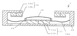
図1〜図4を参照して、本発明の第1の実施形態に係る動電型電気音響変換器1について説明する。なお、図1は、第1の実施形態に係る動電型電気音響変換器1の構造断面図である。図2は、動電型電気音響変換器1の一部を切り取った斜視図である。図3および図4については、後述にて説明する。図1において、動電型電気音響変換器1は、第1の磁極11、第2の磁極12、ヨーク13、ボイスコイル14、および振動板15を備える。なお、図2に示すように、振動方向から見た動電型電気音響変換器1の形状は、円形状である。また、第1の磁極11は本発明の第1の磁極部に、第2の磁極12は本発明の第2の磁極部にそれぞれ相当するものである。
(First embodiment)
With reference to FIGS. 1-4, the electrodynamic electroacoustic transducer 1 which concerns on the 1st Embodiment of this invention is demonstrated. FIG. 1 is a structural cross-sectional view of the electrodynamic electroacoustic transducer 1 according to the first embodiment. FIG. 2 is a perspective view of a part of the electrodynamic electroacoustic transducer 1 cut out. 3 and 4 will be described later. In FIG. 1, the electrodynamic electroacoustic transducer 1 includes a first magnetic pole 11, a second magnetic pole 12, a yoke 13, a voice coil 14, and a diaphragm 15. In addition, as shown in FIG. 2, the shape of the electrodynamic electroacoustic transducer 1 seen from the vibration direction is a circular shape. The first magnetic pole 11 corresponds to the first magnetic pole part of the present invention, and the second magnetic pole 12 corresponds to the second magnetic pole part of the present invention.

第1の磁極11は、マグネット11aおよびマグネット11aの上面(磁極面)に固着されるプレート11bで構成される。第2の磁極12は、マグネット12aおよびマグネット12aの下面(磁極面)に固着されるプレート12bで構成される。プレート11bおよび12bは、マグネット以外の磁性体(例えば鉄など)である。なお、図2に示すように、第1の磁極11の形状は円柱状(柱状体)で構成され、第2の磁極12の形状はドーナツ状の環状体で構成される。   The first magnetic pole 11 includes a magnet 11a and a plate 11b fixed to the upper surface (magnetic pole surface) of the magnet 11a. The second magnetic pole 12 includes a magnet 12a and a plate 12b fixed to the lower surface (magnetic pole surface) of the magnet 12a. The plates 11b and 12b are magnetic bodies (for example, iron etc.) other than a magnet. As shown in FIG. 2, the first magnetic pole 11 has a cylindrical shape (columnar body), and the second magnetic pole 12 has a donut-shaped annular body.

ここで、第2の磁極12は、第1の磁極11に対して動電型電気音響変換器1の前面側に位置する。また、第1の磁極11と第2の磁極12とは、それぞれの中心軸が一致するように配置される。さらに、第2の磁極12の内周形状(内径)は、第1の磁極11の外周形状(外径)より大きい。そして、第1の磁極11の上面と同じ位置に、もしくは上面より少なくとも動電型電気音響変換器1の前面側に第2の磁極12の下面が配置される。すなわち、第2の磁極12は、第1の磁極11から広がった斜め前面方向に位置し、第1の磁極11と第2の磁極12との間に磁気ギャップが形成されるように配置される。なお、第1の磁極11と第2の磁極12との間の磁気ギャップは、例えばそれぞれが対向する空間に渡って均一な寸法になるように形成されてもよい。   Here, the second magnetic pole 12 is located on the front side of the electrodynamic electroacoustic transducer 1 with respect to the first magnetic pole 11. Further, the first magnetic pole 11 and the second magnetic pole 12 are arranged so that their central axes coincide. Further, the inner peripheral shape (inner diameter) of the second magnetic pole 12 is larger than the outer peripheral shape (outer diameter) of the first magnetic pole 11. The lower surface of the second magnetic pole 12 is disposed at the same position as the upper surface of the first magnetic pole 11 or at least on the front surface side of the electrodynamic electroacoustic transducer 1 from the upper surface. In other words, the second magnetic pole 12 is positioned in an oblique front direction extending from the first magnetic pole 11, and is arranged such that a magnetic gap is formed between the first magnetic pole 11 and the second magnetic pole 12. . In addition, the magnetic gap between the 1st magnetic pole 11 and the 2nd magnetic pole 12 may be formed so that it may become a uniform dimension over the space which each opposes, for example.

ヨーク13は、第1の磁極11の下面および第2の磁極12の上面をそれぞれ固設して、第1の磁極11および第2の磁極12を磁気的に結合して支持する。ここで、第1の磁極11の下面および第2の磁極12の上面は、本発明の一方の磁極面にそれぞれ相当するものである。ボイスコイル14は、円環形状を有し、振動板15に固着されて当該振動板15によって上記磁気ギャップ内に保持される。また、ボイスコイル14の内周形状(内径)は、第1の磁極11の外周形状(外径)よりも大きく構成される。ボイスコイル14の外周形状(外径)は、第2の磁極12の内周形状(内径)よりも小さく構成される。つまり、第2の磁極12の内周形状(内径)と第1の磁極11の外周形状(外径)との差は、ボイスコイル14の幅(つまり、ボイスコイル14の外径と内径との差)より大きく構成される。振動板15は、その外周がヨーク13に固設され、第1の磁極11、第2の磁極12、およびヨーク13の間に形成される空隙に位置するように配置される。また、振動方向から見た振動板15の形状は、円形状である。このようなボイスコイル14と第1の磁極11および第2の磁極12との形状および位置関係によって、振動板15が大きく振動してもボイスコイル14と第1の磁極11または第2の磁極12との接触を防止している。   The yoke 13 fixes the lower surface of the first magnetic pole 11 and the upper surface of the second magnetic pole 12, respectively, and supports the first magnetic pole 11 and the second magnetic pole 12 by magnetic coupling. Here, the lower surface of the first magnetic pole 11 and the upper surface of the second magnetic pole 12 respectively correspond to one magnetic pole surface of the present invention. The voice coil 14 has an annular shape, is fixed to the diaphragm 15, and is held in the magnetic gap by the diaphragm 15. Further, the inner peripheral shape (inner diameter) of the voice coil 14 is configured to be larger than the outer peripheral shape (outer diameter) of the first magnetic pole 11. The outer peripheral shape (outer diameter) of the voice coil 14 is configured to be smaller than the inner peripheral shape (inner diameter) of the second magnetic pole 12. That is, the difference between the inner peripheral shape (inner diameter) of the second magnetic pole 12 and the outer peripheral shape (outer diameter) of the first magnetic pole 11 is the width of the voice coil 14 (that is, the outer diameter and inner diameter of the voice coil 14). Difference) is configured to be larger. The diaphragm 15 is disposed so that the outer periphery thereof is fixed to the yoke 13 and is located in a gap formed between the first magnetic pole 11, the second magnetic pole 12, and the yoke 13. Moreover, the shape of the diaphragm 15 viewed from the vibration direction is a circular shape. Due to the shape and positional relationship between the voice coil 14 and the first magnetic pole 11 and the second magnetic pole 12, the voice coil 14 and the first magnetic pole 11 or the second magnetic pole 12 even if the diaphragm 15 vibrates greatly. To prevent contact.

ここで、図1に示すように、振動板15の中央部が外周部に対して凸形状となるようにボイスコイル14が振動板15に固着されている。具体的には、ボイスコイル14の内周形状より内側となる振動板15の中央部は凸形状を形成している。また、ボイスコイル14の外周形状より外側となる振動板15の外周部は、凹形状を形成している。つまり、振動板15は、第1の磁極11と対向する部位が凸形状となり、第2の磁極12と対向する部位が凹形状になっている。このような振動板15の形状によって、振動板15と第1の磁極11および第2の磁極12とが振動によって最も接触しにくい形状となり、従来と同じ厚さで動電型電気音響変換器を構成しても、同じ振幅余裕を確保しながらマグネット11aおよび12aを厚くすることができる。なお、このような効果を期待しない場合、振動板15を上述したような中凸形状に形成しなくてもかまわない。上述したように、ボイスコイル14と第1の磁極11または第2の磁極12とが接触しない構造となっているため、この構造だけでも同じ振幅余裕を確保しながらマグネット11aおよび12aを厚くすることができる。また、振動板15の中央部自体は、図1に示すように、その中心軸に向かって突起する形状を有する。これにより、振動板15の中央部の剛性が高くなり、高域再生に有利となる。   Here, as shown in FIG. 1, the voice coil 14 is fixed to the diaphragm 15 so that the central portion of the diaphragm 15 has a convex shape with respect to the outer peripheral portion. Specifically, the central portion of the diaphragm 15 that is inside the inner peripheral shape of the voice coil 14 forms a convex shape. Further, the outer peripheral portion of the diaphragm 15 that is outside the outer peripheral shape of the voice coil 14 forms a concave shape. That is, the diaphragm 15 has a convex shape at a portion facing the first magnetic pole 11 and a concave shape at a portion opposed to the second magnetic pole 12. Due to the shape of the diaphragm 15, the diaphragm 15 and the first magnetic pole 11 and the second magnetic pole 12 are in a shape that is most unlikely to come into contact by vibration. Even if it comprises, magnet 11a and 12a can be thickened, ensuring the same amplitude margin. If such an effect is not expected, the diaphragm 15 does not have to be formed in the middle convex shape as described above. As described above, since the voice coil 14 and the first magnetic pole 11 or the second magnetic pole 12 are not in contact with each other, the magnets 11a and 12a are made thicker while ensuring the same amplitude margin with this structure alone. Can do. Further, as shown in FIG. 1, the central portion itself of the diaphragm 15 has a shape protruding toward its central axis. As a result, the rigidity of the central portion of the diaphragm 15 is increased, which is advantageous for high-frequency reproduction.

また、ボイスコイル14の外周形状より外側である振動板15の外周部には、図1に示すように、エッジ部15aが形成されている。このエッジ部15aによって、振動板15は上下方向に振動可能になる。このエッジ部15a自体の形状は、平板状であってもよいが、図1に示すように、断面がロール状となる形状であってもよい。エッジ部15a自体の形状を断面がロール状となる形状にすることで、振動板15の振幅に対する復元力がさらに線形となり、例えば再生音の歪がさらに低減し、音質を向上する効果が得られる。なお、図1に示すように、エッジ部15aは、その一部が少なくとも第2の磁極部12と対向するように形成されている。したがって、第2の磁極部12と対向する振動板15全体にエッジ部15aが形成されてもよい。また、エッジ部15aは、エッジ部15a以外の振動板15と一体で構成されてもよいし、エッジ部15a以外の振動板15と別体で構成されてもよい。   Further, as shown in FIG. 1, an edge portion 15 a is formed on the outer peripheral portion of the diaphragm 15 that is outside the outer peripheral shape of the voice coil 14. The edge portion 15a allows the diaphragm 15 to vibrate in the vertical direction. The shape of the edge portion 15a itself may be a flat plate shape, but may be a shape whose cross section is a roll shape as shown in FIG. By making the shape of the edge portion 15a itself into a roll-shaped cross section, the restoring force with respect to the amplitude of the diaphragm 15 becomes more linear, and for example, the effect of further reducing distortion of reproduced sound and improving sound quality can be obtained. . As shown in FIG. 1, the edge portion 15 a is formed so that a part thereof faces at least the second magnetic pole portion 12. Therefore, the edge portion 15 a may be formed on the entire diaphragm 15 facing the second magnetic pole portion 12. The edge portion 15a may be configured integrally with the diaphragm 15 other than the edge portion 15a, or may be configured separately from the diaphragm 15 other than the edge portion 15a.

なお、マグネット11aおよびマグネット12aは、振動板15の振動方向に同極に(極性が同じ方向となるように)着磁されている。また、ヨーク13には、動電型電気音響変換器1の前面側に音を放射させるための音孔と、背面側に排圧用の音孔とが形成されている。以下、動電型電気音響変換器1の動作について説明する。   The magnet 11a and the magnet 12a are magnetized to have the same polarity in the vibration direction of the diaphragm 15 (so that the polarities are in the same direction). The yoke 13 is formed with a sound hole for radiating sound to the front side of the electrodynamic electroacoustic transducer 1 and a sound hole for exhausting pressure on the back side. Hereinafter, the operation of the electrodynamic electroacoustic transducer 1 will be described.

上述したように、第1の磁極11および第2の磁極12の間に磁気ギャップが形成されている。その磁気ギャップ内に位置するボイスコイル14に信号電流が流れると、その電流の大きさとボイスコイル位置における磁束密度との積に比例した駆動力が発生する。そして、その駆動力によって振動板15が振動することにより、音が放射される。このように、本実施形態に係る電気音響変換器は動電型である。つまり、本実施形態に係る電気音響変換器はボイスコイル14に直接、電気音響信号を印加する変換器であり、上述した電磁誘導型とは異なる変換器である。   As described above, a magnetic gap is formed between the first magnetic pole 11 and the second magnetic pole 12. When a signal current flows through the voice coil 14 located in the magnetic gap, a driving force proportional to the product of the magnitude of the current and the magnetic flux density at the voice coil position is generated. Then, the diaphragm 15 vibrates by the driving force, so that sound is emitted. Thus, the electroacoustic transducer according to this embodiment is an electrodynamic type. That is, the electroacoustic transducer according to the present embodiment is a transducer that directly applies an electroacoustic signal to the voice coil 14, and is a transducer different from the electromagnetic induction type described above.

ここで、従来の動電型電気音響変換器は、マグネットやヨークが振動板とボイスコイルを上下から挟み込むような構造であった。そのため、振動板の振動時にボイスコイルがマグネットおよびヨークに接触することを防止する必要があり、マグネットの厚さが制限されていた。しかしながら、本実施形態における動電型電気音響変換器1は、ボイスコイル14の内周が第1の磁極11の外周よりも大きく、ボイスコイル14の外周が第2の磁極12の内周よりも小さく構成されるため、振動板15が大きく振動してもボイスコイル14と第1の磁極11または第2の磁極12とが接触しない。また、振動板15と磁極(第1の磁極11および第2の磁極12)とが振動によって接触しにくい形状および位置に配置することにより、従来と同じ厚さで動電型電気音響変換器を構成しても、同じ振幅余裕を確保しながらマグネット11aおよび12aを厚くすることができる。その結果、ボイスコイル14の位置における磁束密度を大きくすることができる。また、マグネット11aおよび12aの厚みが増すことで、ネオジウムなどを用いた高エネルギー積マグネットを用いた場合でもパーミアンス係数が高くなり、従来よりも高温減磁に強くなる。すなわち、動電型電気音響変換器1の温度信頼性が向上する。   Here, the conventional electrodynamic electroacoustic transducer has a structure in which a magnet and a yoke sandwich a diaphragm and a voice coil from above and below. Therefore, it is necessary to prevent the voice coil from coming into contact with the magnet and the yoke during vibration of the diaphragm, and the thickness of the magnet is limited. However, in the electrodynamic electroacoustic transducer 1 according to this embodiment, the inner circumference of the voice coil 14 is larger than the outer circumference of the first magnetic pole 11, and the outer circumference of the voice coil 14 is larger than the inner circumference of the second magnetic pole 12. Since it is configured to be small, the voice coil 14 does not contact the first magnetic pole 11 or the second magnetic pole 12 even if the diaphragm 15 vibrates greatly. In addition, by arranging the diaphragm 15 and the magnetic poles (the first magnetic pole 11 and the second magnetic pole 12) in a shape and a position where they are difficult to come into contact with each other by vibration, the electrodynamic electroacoustic transducer can be formed with the same thickness as the conventional one. Even if it comprises, magnet 11a and 12a can be thickened, ensuring the same amplitude margin. As a result, the magnetic flux density at the position of the voice coil 14 can be increased. Further, by increasing the thickness of the magnets 11a and 12a, the permeance coefficient is increased even when a high energy product magnet using neodymium or the like is used, and it is more resistant to high temperature demagnetization than in the past. That is, the temperature reliability of the electrodynamic electroacoustic transducer 1 is improved.

ここで、図3を参照して、本実施形態における第1の磁極11および第2の磁極12が構成する磁束の流れについて説明する。なお、図3は、本実施形態における磁気回路の一例を有限要素法によって磁場解析して、磁束の流れをベクトルによって表した図である。図3において、磁束はボイスコイル14を通り、振動方向に垂直な方向成分を持つ駆動用の磁束が形成されていることがわかる。このように、第1の磁極11と第2の磁極12とが、振動板15の振動方向に対して斜め方向の位置関係にあるため、マグネット11aおよびマグネット12aを当該振動方向に同極に着磁することによって、振動方向に垂直な方向成分を持つ駆動用の磁束を形成している。   Here, with reference to FIG. 3, the flow of the magnetic flux which the 1st magnetic pole 11 and the 2nd magnetic pole 12 in this embodiment comprise is demonstrated. FIG. 3 is a diagram showing an example of a magnetic circuit according to the present embodiment, in which a magnetic field analysis is performed by a finite element method, and a magnetic flux flow is represented by a vector. In FIG. 3, it can be seen that the magnetic flux passes through the voice coil 14 and a driving magnetic flux having a direction component perpendicular to the vibration direction is formed. Thus, since the first magnetic pole 11 and the second magnetic pole 12 are in an oblique positional relationship with respect to the vibration direction of the diaphragm 15, the magnet 11a and the magnet 12a are attached to the same polarity in the vibration direction. By magnetizing, a driving magnetic flux having a direction component perpendicular to the vibration direction is formed.

また、図4は、磁気回路全体の厚さとマグネットの材料とがそれぞれ同一という条件の下で、図39に示す従来例の磁気回路と、図1に示す本実施形態の磁気回路との2つの磁気回路について、ボイスコイル位置での磁束密度を比較した図である。図4において、横軸は振動板15の振幅を表し、縦軸はボイスコイル位置の磁束密度を表す。本実施形態において説明した磁気回路構造をとることで、従来よりもボイスコイル位置での磁束密度が向上していることがわかる。   FIG. 4 shows two examples of the conventional magnetic circuit shown in FIG. 39 and the magnetic circuit of the present embodiment shown in FIG. 1 under the condition that the thickness of the entire magnetic circuit and the material of the magnet are the same. It is the figure which compared the magnetic flux density in a voice coil position about a magnetic circuit. In FIG. 4, the horizontal axis represents the amplitude of the diaphragm 15, and the vertical axis represents the magnetic flux density at the voice coil position. By adopting the magnetic circuit structure described in the present embodiment, it can be seen that the magnetic flux density at the voice coil position is improved as compared with the conventional case.

以上のように、本実施形態における動電型電気音響変換器は、同じ厚さの電気音響変換器であっても、より能率が高い電気音響変換器を提供できる。また、同じ能率であっても、より小型、薄型の電気音響変換器を提供できる。さらに、第1の磁極11および第2の磁極12の着磁方向は同じであるため、電気音響変換器を組み立てた後に着磁することが可能となる。その結果、2つのマグネットを逆方向に着磁する場合に比べて製造工数上有利となる。   As described above, even if the electrodynamic electroacoustic transducer in the present embodiment is an electroacoustic transducer having the same thickness, an electroacoustic transducer with higher efficiency can be provided. In addition, even with the same efficiency, a smaller and thinner electroacoustic transducer can be provided. Furthermore, since the magnetization directions of the first magnetic pole 11 and the second magnetic pole 12 are the same, it is possible to magnetize after the electroacoustic transducer is assembled. As a result, it is advantageous in terms of manufacturing man-hours compared to the case where the two magnets are magnetized in opposite directions.

なお、以上の説明では、振動方向から見た動電型電気音響変換器1、第1の磁極11、第2の磁極12、および振動板15の形状は円形状としたが、楕円形状であってもよい。   In the above description, the electrodynamic electroacoustic transducer 1, the first magnetic pole 11, the second magnetic pole 12, and the diaphragm 15 as viewed from the vibration direction are circular, but are elliptical. May be.

また、上述した動電型電気音響変換器1において、第1の磁極11は円柱状で構成されるとしたが、円筒状の柱状体で構成されてもよい。換言すれば、第1の磁極11は、図1に示した第1の磁極11の円柱状と同軸の貫通孔(中空孔)が形成された柱状体で構成されてもよい。さらに換言すれば、第1の磁極11は、その中央に空隙が形成された環状体で構成されてもよい。また、第1の磁極11の上面より動電型電気音響変換器1の背面側に第2の磁極12の下面が配置されてもよい。図5は、第1の磁極11の形状を同軸の貫通孔が形成された円柱状で構成し、第1の磁極11の上面より動電型電気音響変換器1の背面側に第2の磁極12の下面を配置した構造断面図である。第2の磁極12は、第1の磁極11と第2の磁極12との間に磁気ギャップが形成されるように配置される。またこのとき、図5に示すようにヨーク13には、上記第1の磁極部11に形成された貫通孔と同径の音孔が形成されている。   In the electrodynamic electroacoustic transducer 1 described above, the first magnetic pole 11 is formed in a columnar shape, but may be formed in a cylindrical columnar body. In other words, the first magnetic pole 11 may be constituted by a columnar body in which a through hole (hollow hole) coaxial with the columnar shape of the first magnetic pole 11 shown in FIG. 1 is formed. In other words, the first magnetic pole 11 may be formed of an annular body having a gap formed at the center thereof. Further, the lower surface of the second magnetic pole 12 may be arranged on the back side of the electrodynamic electroacoustic transducer 1 from the upper surface of the first magnetic pole 11. In FIG. 5, the shape of the first magnetic pole 11 is configured as a columnar shape having a coaxial through hole, and the second magnetic pole is formed on the back side of the electrodynamic electroacoustic transducer 1 from the upper surface of the first magnetic pole 11. 12 is a structural sectional view in which the lower surface of 12 is arranged. The second magnetic pole 12 is disposed such that a magnetic gap is formed between the first magnetic pole 11 and the second magnetic pole 12. At this time, as shown in FIG. 5, a sound hole having the same diameter as the through hole formed in the first magnetic pole portion 11 is formed in the yoke 13.

図5に示す構造は、第1の磁極11の同軸上に形成された貫通孔により、第1の磁極11の上面と振動板15の下面との間にある空気が特に抜けやすい構造となる。つまり、振動板15の下面の音が下方向に抜けやすくなる効果がある。また、第1の磁極11の上面より動電型電気音響変換器1の背面側に第2の磁極12の下面が配置される。つまり、図5に示す構造は、動電型電気音響変換器自体の厚みを同じとした場合に図1に示した構造と比べてマグネット11aおよびマグネット12aを厚くすることができる構造であるため、高能率の点で有利となる構造である。   The structure shown in FIG. 5 is a structure in which air between the upper surface of the first magnetic pole 11 and the lower surface of the diaphragm 15 is particularly easy to escape due to the through hole formed coaxially with the first magnetic pole 11. That is, there is an effect that the sound on the lower surface of the diaphragm 15 can be easily removed downward. In addition, the lower surface of the second magnetic pole 12 is disposed on the back side of the electrodynamic electroacoustic transducer 1 from the upper surface of the first magnetic pole 11. That is, the structure shown in FIG. 5 is a structure in which the magnet 11a and the magnet 12a can be made thicker than the structure shown in FIG. 1 when the thickness of the electrodynamic electroacoustic transducer itself is the same. This structure is advantageous in terms of high efficiency.

また、動電型電気音響変換器1において、第1の磁極11のプレート11bを省略してもよい。図6は、上述した動電型電気音響変換器1において、プレート11bを省略した構造断面図である。図7は、プレート11bを省略した動電型電気音響変換器1の一部を切り取った斜視図である。図6および図7に示される動電型電気音響変換器1は、プレート11bが省略されていることにより、マグネット11aの動作点は下がるが、製造において材料、工数の面で有利となる。また、図6および図7において、第1の磁極11をマグネット11aで構成しているが、鉄等のマグネット以外の磁性体で構成してもよい。   In the electrodynamic electroacoustic transducer 1, the plate 11b of the first magnetic pole 11 may be omitted. FIG. 6 is a structural cross-sectional view in which the plate 11b is omitted in the electrodynamic electroacoustic transducer 1 described above. FIG. 7 is a perspective view of a part of the electrodynamic electroacoustic transducer 1 with the plate 11b omitted. In the electrodynamic electroacoustic transducer 1 shown in FIGS. 6 and 7, the operating point of the magnet 11a is lowered due to the omission of the plate 11b, but it is advantageous in terms of materials and man-hours in manufacturing. 6 and 7, the first magnetic pole 11 is composed of the magnet 11a, but may be composed of a magnetic material other than a magnet such as iron.

また、動電型電気音響変換器1において、第2の磁極12のプレート12bを省略してもよい。図8は、上述した動電型電気音響変換器1において、プレート12bを省略した構造断面図である。図9は、プレート12bを省略した動電型電気音響変換器1の一部を切り取った斜視図である。図8および図9に示される動電型電気音響変換器1は、プレート12bが省略されていることにより、マグネット12aの動作点は下がるが、製造において材料、工数の面で有利となる。また、図8および図9において、第2の磁極12をマグネット12aで構成しているが、鉄等のマグネット以外の磁性体で構成してもよい。   In the electrodynamic electroacoustic transducer 1, the plate 12b of the second magnetic pole 12 may be omitted. FIG. 8 is a structural cross-sectional view in which the plate 12b is omitted from the electrodynamic electroacoustic transducer 1 described above. FIG. 9 is a perspective view of a part of the electrodynamic electroacoustic transducer 1 with the plate 12b omitted. In the electrodynamic electroacoustic transducer 1 shown in FIGS. 8 and 9, the operating point of the magnet 12a is lowered because the plate 12b is omitted, but it is advantageous in terms of materials and man-hours in manufacturing. 8 and 9, the second magnetic pole 12 is composed of the magnet 12a, but it may be composed of a magnetic material other than a magnet such as iron.

さらに、動電型電気音響変換器1において、第1の磁極11のプレート11bおよび第2の磁極12のプレート12bを共に省略してもよい。図10は、上述した動電型電気音響変換器1において、プレート11bおよびプレート12bを省略した構造断面図である。図11は、プレート11bおよびプレート12bを省略した動電型電気音響変換器1の一部を切り取った斜視図である。図10および図11に示される動電型電気音響変換器1は、プレート11bおよびプレート12bが省略されていることにより、マグネット11aおよびマグネット12aの動作点は下がるが、製造において材料、工数の面で有利となる。また、図10および図11において、第1の磁極11はマグネット11aで、第2の磁極12はマグネット12aでそれぞれ構成しているが、いずれか一方の磁極のマグネットを鉄等のマグネット以外の磁性体で構成してもよい。   Further, in the electrodynamic electroacoustic transducer 1, both the plate 11b of the first magnetic pole 11 and the plate 12b of the second magnetic pole 12 may be omitted. FIG. 10 is a structural cross-sectional view in which the plate 11b and the plate 12b are omitted from the electrodynamic electroacoustic transducer 1 described above. FIG. 11 is a perspective view of a part of the electrodynamic electroacoustic transducer 1 in which the plate 11b and the plate 12b are omitted. In the electrodynamic electroacoustic transducer 1 shown in FIG. 10 and FIG. 11, the operating points of the magnet 11a and the magnet 12a are lowered by omitting the plate 11b and the plate 12b. Is advantageous. 10 and 11, the first magnetic pole 11 is composed of a magnet 11a, and the second magnetic pole 12 is composed of a magnet 12a. However, one of the magnetic poles is made of a magnet other than a magnet such as iron. It may be composed of a body.

このように、第1の実施形態に係る動電型電気音響変換器によれば、第2の磁極12の内周形状は第1の磁極11の外周形状より大きく、第2の磁極12は第1の磁極11から広がった斜め前面方向に位置し、第1および第2の磁極が振動板の振動方向に重なり合わない構造となる。そして、振動板を第1および第2の磁極から振幅余裕だけ離れるような形状とすることで、従来と同じ厚さの動電型電気音響変換器を実現する場合において、従来に比べてマグネットの振動方向の厚みを厚くすることができる。その結果、ボイスコイル位置における磁束密度が向上し、従来と同じ厚さでも高能率の動電型電気音響変換器を実現することができる。   As described above, according to the electrodynamic electroacoustic transducer according to the first embodiment, the inner peripheral shape of the second magnetic pole 12 is larger than the outer peripheral shape of the first magnetic pole 11, and the second magnetic pole 12 is The first magnetic pole 11 is located in an oblique front direction extending from the magnetic pole 11, and the first and second magnetic poles do not overlap with the vibration direction of the diaphragm. Then, by forming the diaphragm so as to be separated from the first and second magnetic poles by an amplitude margin, in the case of realizing an electrodynamic electroacoustic transducer having the same thickness as the conventional one, the magnet is compared with the conventional one. The thickness in the vibration direction can be increased. As a result, the magnetic flux density at the voice coil position is improved, and a highly efficient electrodynamic electroacoustic transducer can be realized with the same thickness as the conventional one.

また、第1の実施形態に係る動電型電気音響変換器によれば、ボイスコイルの内周形状は第1の磁極の外周形状よりも大きく、ボイスコイルの外周形状は第2の磁極の内周形状よりも小さい構造となる。これにより、ボイスコイルの振動方向に第1および第2の磁極が存在しないため、振動板を第1および第2の磁極から振幅余裕だけ離れるような形状とすることで、マグネットの振動方向の厚みをさらに厚くすることができる。つまり、従来では、マグネット、ヨーク、およびボイスコイルが、振動板振動方向に重なり合う構成であったためにマグネット厚さが制限されていたのに対し、ボイスコイルおよびマグネットが厚さ方向に重なり合わない構造とし、振動板の形状を振動板振動時に第1および第2の磁極と接触しにくい形状とすることによって、マグネットをさらに厚くすることができる。これにより、ボイスコイル位置における磁束密度がさらに向上し、薄くても能率の高い電気音響変換器が実現できる。なお、このようなボイスコイルの形状による効果を期待しない場合には、ボイスコイルの内周形状が第1の磁極の外周形状よりも小さい、および/または、ボイスコイルの外周形状が第2の磁極の内周形状よりも大きい構造であってもよい。   Further, according to the electrodynamic electroacoustic transducer according to the first embodiment, the inner peripheral shape of the voice coil is larger than the outer peripheral shape of the first magnetic pole, and the outer peripheral shape of the voice coil is the inner periphery of the second magnetic pole. The structure is smaller than the circumferential shape. Thus, since the first and second magnetic poles do not exist in the vibration direction of the voice coil, the thickness of the vibration direction of the magnet can be obtained by making the diaphragm away from the first and second magnetic poles by an amplitude margin. Can be made even thicker. That is, in the past, the magnet, yoke, and voice coil were configured to overlap in the diaphragm vibration direction, so the magnet thickness was limited, whereas the voice coil and magnet did not overlap in the thickness direction. By making the shape of the diaphragm difficult to contact the first and second magnetic poles during vibration of the diaphragm, the magnet can be made thicker. As a result, the magnetic flux density at the voice coil position is further improved, and an electroacoustic transducer with high efficiency can be realized even if it is thin. When the effect due to the shape of the voice coil is not expected, the inner peripheral shape of the voice coil is smaller than the outer peripheral shape of the first magnetic pole and / or the outer peripheral shape of the voice coil is the second magnetic pole. The structure may be larger than the inner peripheral shape.

さらに、マグネットが厚くなることで、一般的に小型薄型スピーカに使われているネオジウムを原料としたマグネットは、パーミアンス係数が増加し高温減磁に強くなる。したがって、温度信頼性を向上、もしくは同じ温度信頼性を維持しながら、よりエネルギー積の高いマグネットを用いることも可能となる。このことにより、さらにボイスコイル位置における磁束密度を向上でき、より能率のよい小型、薄型の電気音響変換器が実現できる。   Furthermore, as magnets become thicker, magnets made from neodymium, which are generally used for small thin speakers, have increased permeance coefficients and are resistant to high temperature demagnetization. Therefore, it is possible to use a magnet having a higher energy product while improving the temperature reliability or maintaining the same temperature reliability. As a result, the magnetic flux density at the voice coil position can be further improved, and a more efficient small and thin electroacoustic transducer can be realized.

また、第1の磁極と第2の磁極とが同極の極性を有するため、第1の磁極と第2の磁極とを双方ともマグネットを含む磁性体で構成された場合でも、電気音響変換器を組み立てた後に着磁することが可能で、2つのマグネットを逆方向に着磁する場合に比べて製造上有利となる。   Further, since the first magnetic pole and the second magnetic pole have the same polarity, even when both the first magnetic pole and the second magnetic pole are made of a magnetic material including a magnet, the electroacoustic transducer is used. Can be magnetized after assembling the two magnets, which is advantageous in manufacturing compared to the case where the two magnets are magnetized in opposite directions.

また、第1の実施形態に係る動電型電気音響変換器は、磁気ギャップ中の磁束密度を低下させる原因となる駆動用1次コイル314を用いる電磁誘導型ではないので、当該電磁誘導型と同じ厚さにした場合に、電磁誘導型に比べて磁気ギャップの磁束密度を向上させることができる。   In addition, the electrodynamic electroacoustic transducer according to the first embodiment is not an electromagnetic induction type using the driving primary coil 314 that causes a decrease in the magnetic flux density in the magnetic gap. When the thickness is the same, the magnetic flux density of the magnetic gap can be improved as compared with the electromagnetic induction type.

(第2の実施形態)
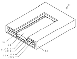
図12および図13を参照して、本発明の第2の実施形態に係る動電型電気音響変換器2について説明する。なお、図12は、第2の実施形態に係る動電型電気音響変換器2の構造断面図である。図13は、動電型電気音響変換器2の一部を切り取った斜視図である。図12において、動電型電気音響変換器2は、第1の磁極21、第2の磁極22、ヨーク23、ボイスコイル24、および振動板25を備える。なお、図13に示すように、振動方向から見た動電型電気音響変換器2の形状は、矩形である。また、第1の磁極21は本発明の第1の磁極部に、第2の磁極22は本発明の第2の磁極部にそれぞれ相当するものである。
(Second Embodiment)
With reference to FIG. 12 and FIG. 13, the electrodynamic electroacoustic transducer 2 according to the second embodiment of the present invention will be described. FIG. 12 is a structural sectional view of the electrodynamic electroacoustic transducer 2 according to the second embodiment. FIG. 13 is a perspective view of a part of the electrodynamic electroacoustic transducer 2 cut out. In FIG. 12, the electrodynamic electroacoustic transducer 2 includes a first magnetic pole 21, a second magnetic pole 22, a yoke 23, a voice coil 24, and a diaphragm 25. In addition, as shown in FIG. 13, the shape of the electrodynamic electroacoustic transducer 2 viewed from the vibration direction is a rectangle. The first magnetic pole 21 corresponds to the first magnetic pole part of the present invention, and the second magnetic pole 22 corresponds to the second magnetic pole part of the present invention.

第1の磁極21は、マグネット21aおよびマグネット21aの上面に固着されるプレート21bで構成される。第2の磁極22は、マグネット22aおよびマグネット22aの下面に固着されるプレート22bで構成される。プレート21bおよび22bは、マグネット以外の磁性体(例えば鉄など)である。なお、図13に示すように、第1の磁極21の形状は直方体(柱状体)で構成され、第2の磁極22の形状は直方体の中央部に矩形の開口部が形成された環状体で構成される。   The first magnetic pole 21 includes a magnet 21a and a plate 21b fixed to the upper surface of the magnet 21a. The second magnetic pole 22 includes a magnet 22a and a plate 22b fixed to the lower surface of the magnet 22a. The plates 21b and 22b are magnetic bodies (for example, iron etc.) other than magnets. As shown in FIG. 13, the shape of the first magnetic pole 21 is a rectangular parallelepiped (columnar body), and the shape of the second magnetic pole 22 is an annular body in which a rectangular opening is formed at the center of the rectangular parallelepiped. Composed.

ここで、第2の磁極22は、第1の磁極21に対して動電型電気音響変換器2の前面側に位置する。また、第1の磁極21と第2の磁極22とは、それぞれの中心軸が一致するように配置される。さらに、第2の磁極22の内周形状(開口部の内辺長さ)は、第1の磁極21の外周形状(上記中心軸に平行な辺を除いた外辺長さ)より大きい。そして、第1の磁極21の上面と同じ位置に、もしくは上面より少なくとも動電型電気音響変換器2の前面側に第2の磁極22の下面が配置される。すなわち、第2の磁極22は、第1の磁極21から広がった斜め前面方向に位置し、第1の磁極21と第2の磁極22との間に磁気ギャップが形成されるように配置される。なお、第1の磁極21と第2の磁極22との間の磁気ギャップは、例えば全周に渡って均一な寸法になるように形成されている。   Here, the second magnetic pole 22 is located on the front side of the electrodynamic electroacoustic transducer 2 with respect to the first magnetic pole 21. In addition, the first magnetic pole 21 and the second magnetic pole 22 are arranged so that their central axes coincide. Furthermore, the inner peripheral shape of the second magnetic pole 22 (the inner side length of the opening) is larger than the outer peripheral shape of the first magnetic pole 21 (the outer side length excluding the side parallel to the central axis). The lower surface of the second magnetic pole 22 is disposed at the same position as the upper surface of the first magnetic pole 21 or at least on the front surface side of the electrodynamic electroacoustic transducer 2 from the upper surface. In other words, the second magnetic pole 22 is positioned in the oblique front direction extending from the first magnetic pole 21 and is disposed so that a magnetic gap is formed between the first magnetic pole 21 and the second magnetic pole 22. . In addition, the magnetic gap between the 1st magnetic pole 21 and the 2nd magnetic pole 22 is formed so that it may become a uniform dimension over the perimeter, for example.

ヨーク23は、第1の磁極21の下面および第2の磁極22の上面をそれぞれ固設して、第1の磁極21および第2の磁極22を磁気的に結合して支持する。ここで、第1の磁極21の下面および第2の磁極22の上面は、本発明の一方の磁極面にそれぞれ相当するものである。ボイスコイル24は、矩形の枠形状を有し、振動板25に固着されて当該振動板25によって上記磁気ギャップ内に保持される。また、ボイスコイル24の内周形状(内辺)は、第1の磁極21の外周形状(ボイスコイル24の内辺と対向する外辺)よりも大きく構成される。ボイスコイル24の外周形状(外辺)は、第2の磁極22の内周形状(ボイスコイル24の外辺と対向する内辺)よりも小さく構成される。つまり、第2の磁極22の内周形状(内辺)と第1の磁極21の外周形状(第2の磁極12の内辺と対向する外辺)との差は、ボイスコイル24枠幅より大きく構成される。振動板25は、その外周がヨーク23に固設され、第1の磁極21、第2の磁極22、およびヨーク23の間に形成される空隙に位置するように配置される。また、振動方向から見た振動板25の形状は、矩形である。また、振動板25には、上述した振動板15のエッジ部15aと同様のエッジ部25aが形成されている。   The yoke 23 fixes the lower surface of the first magnetic pole 21 and the upper surface of the second magnetic pole 22 respectively, and supports the first magnetic pole 21 and the second magnetic pole 22 by magnetic coupling. Here, the lower surface of the first magnetic pole 21 and the upper surface of the second magnetic pole 22 correspond to one of the magnetic pole surfaces of the present invention. The voice coil 24 has a rectangular frame shape, is fixed to the diaphragm 25 and is held in the magnetic gap by the diaphragm 25. The inner peripheral shape (inner side) of the voice coil 24 is configured to be larger than the outer peripheral shape of the first magnetic pole 21 (outer side opposite to the inner side of the voice coil 24). The outer peripheral shape (outer side) of the voice coil 24 is configured to be smaller than the inner peripheral shape of the second magnetic pole 22 (inner side facing the outer side of the voice coil 24). That is, the difference between the inner peripheral shape (inner side) of the second magnetic pole 22 and the outer peripheral shape of the first magnetic pole 21 (outer side opposite to the inner side of the second magnetic pole 12) is larger than the frame width of the voice coil 24. Largely composed. The diaphragm 25 is disposed so that the outer periphery thereof is fixed to the yoke 23 and is located in a gap formed between the first magnetic pole 21, the second magnetic pole 22, and the yoke 23. Moreover, the shape of the diaphragm 25 viewed from the vibration direction is a rectangle. Further, the diaphragm 25 is formed with an edge portion 25a similar to the edge portion 15a of the diaphragm 15 described above.

なお、マグネット21aおよびマグネット22aは、振動板25の振動方向に同極に着磁されている。また、ヨーク23には、動電型電気音響変換器2の前面側に音を放射させるための音孔と、背面側に排圧用の音孔とが形成されている。   The magnet 21a and the magnet 22a are magnetized in the same polarity in the vibration direction of the diaphragm 25. Further, the yoke 23 is formed with a sound hole for radiating sound to the front side of the electrodynamic electroacoustic transducer 2 and a sound hole for pressure relief on the back side.

なお、第2の実施形態に係る動電型電気音響変換器2は、第1の実施形態で説明した動電型電気音響変換器1に対して形状が異なるのみであり、動電型電気音響変換器2の動作は動電型電気音響変換器1の動作と同様であるので詳細な説明を省略する。また、第2の実施形態に係る動電型電気音響変換器2は、第1の実施形態と同様の効果が得られる。   The electrodynamic electroacoustic transducer 2 according to the second embodiment is different from the electrodynamic electroacoustic transducer 1 described in the first embodiment only in the shape, and the electrodynamic electroacoustic transducer Since the operation of the transducer 2 is the same as that of the electrodynamic electroacoustic transducer 1, detailed description thereof is omitted. Further, the electrodynamic electroacoustic transducer 2 according to the second embodiment can obtain the same effects as those of the first embodiment.

ここで、動電型電気音響変換器2の振動方向から見た外形状、第1の磁極21、第2の磁極22、および振動板25の形状は、矩形である。一般的に、電子機器の筐体内部には矩形空間が多い。したがって、動電型電気音響変換器2の振動方向から見た形状が矩形であるため、電子機器内部の空間に無駄なく搭載することができる。すなわち、動電型電気音響変換器2は、円形状の動電型電気音響変換器1に比べ、同一空間内における空間利用率が向上する。また、振動板25の形状も矩形であるため、同一空間内における振動板の面積を多く確保できる。すなわち、動電型電気音響変換器2の振動板25の面積を多く確保した分だけ、能率を向上させることができる。   Here, the outer shape of the electrodynamic electroacoustic transducer 2 viewed from the vibration direction, the first magnetic pole 21, the second magnetic pole 22, and the diaphragm 25 are rectangular. Generally, there are many rectangular spaces inside the housing of an electronic device. Therefore, since the shape of the electrodynamic electroacoustic transducer 2 viewed from the vibration direction is rectangular, the electrodynamic electroacoustic transducer 2 can be mounted without waste in the space inside the electronic device. That is, the electrodynamic electroacoustic transducer 2 has a higher space utilization rate in the same space than the circular electrodynamic electroacoustic transducer 1. Further, since the shape of the diaphragm 25 is rectangular, a large area of the diaphragm in the same space can be secured. That is, the efficiency can be improved as much as the area of the diaphragm 25 of the electrodynamic electroacoustic transducer 2 is secured.

なお、第1の実施形態と同様に、動電型電気音響変換器2のプレート21bおよび22bの少なくとも一方を省略してもよい。また、第1の磁極21がマグネット21aおよび第2の磁極22がマグネット22aを含んでいるが、何れか一方の磁極のマグネットが鉄等のマグネット以外の磁性体で構成されてもよい。   Note that, as in the first embodiment, at least one of the plates 21b and 22b of the electrodynamic electroacoustic transducer 2 may be omitted. Further, although the first magnetic pole 21 includes the magnet 21a and the second magnetic pole 22 includes the magnet 22a, the magnet of any one of the magnetic poles may be made of a magnetic material other than a magnet such as iron.

また、動電型電気音響変換器2の振動方向から見た外形状、第1の磁極21、第2の磁極22、および振動板25の形状を矩形としたが、その他の多角形形状であってもよい。また、電子部品筐体内部の形状や用途にあわせた形状であってもよい。例えば、平行に向かい合う2辺が他の2辺に比べて極端に短くなる細長い四角形形状であってもよい。また、例えば多角形形状の角や辺の全体、または一部に丸みをもつ形状であってもよい。   The outer shape of the electrodynamic electroacoustic transducer 2 viewed from the vibration direction, the first magnetic pole 21, the second magnetic pole 22, and the diaphragm 25 are rectangular, but other polygonal shapes are used. May be. Moreover, the shape according to the shape inside an electronic component housing | casing and a use may be sufficient. For example, it may be an elongated rectangular shape in which two sides facing in parallel are extremely shorter than the other two sides. Further, for example, the shape may be a shape having rounded corners or sides of a polygonal shape or a part thereof.

また、上述した動電型電気音響変換器2において、第1の磁極21は直方体で構成されるとしたが、図14および図15に示すように矩形の枠形状であってもよい。換言すれば、第1の磁極21は、図12および図13に示した第1の磁極21の直方体に対して同軸の矩形の貫通孔(中空孔)が形成された柱状体で構成されてもよい。さらに換言すれば、第1の磁極21は、矩形の空隙が形成された環状体で構成されてもよい。図14は、第1の磁極21の形状が枠形状となる構成を示す動電型電気音響変換器2の構造断面図である。図15は、第1の磁極21の形状が枠形状となる構成を示す動電型電気音響変換器2の一部を切り取った斜視図である。第2の磁極22は、第1の磁極21と第2の磁極22との間に磁気ギャップが形成されるように配置される。またこのとき、図14に示すようにヨーク23には、上記第1の磁極部21に形成された貫通孔と同径の音孔が形成されている。図14および図15に示す構造は、第1の磁極21の同軸上に形成された貫通孔により、第1の磁極21の上面と振動板25の下面との間にある空気が特に抜けやすい構造となる。つまり、図14および図15に示される構造は、振動板15の下面の音が下方向に抜けやすくなるという効果を発揮する。   In the electrodynamic electroacoustic transducer 2 described above, the first magnetic pole 21 is formed of a rectangular parallelepiped, but may be a rectangular frame as shown in FIGS. In other words, the first magnetic pole 21 may be a columnar body in which a rectangular through hole (hollow hole) coaxial with the rectangular parallelepiped of the first magnetic pole 21 shown in FIGS. 12 and 13 is formed. Good. In other words, the first magnetic pole 21 may be formed of an annular body in which a rectangular gap is formed. FIG. 14 is a structural cross-sectional view of the electrodynamic electroacoustic transducer 2 showing a configuration in which the shape of the first magnetic pole 21 is a frame shape. FIG. 15 is a perspective view of a part of the electrodynamic electroacoustic transducer 2 showing a configuration in which the shape of the first magnetic pole 21 is a frame shape. The second magnetic pole 22 is disposed such that a magnetic gap is formed between the first magnetic pole 21 and the second magnetic pole 22. At this time, as shown in FIG. 14, the yoke 23 is formed with a sound hole having the same diameter as the through hole formed in the first magnetic pole portion 21. The structure shown in FIGS. 14 and 15 is a structure in which air between the upper surface of the first magnetic pole 21 and the lower surface of the diaphragm 25 is particularly easy to escape by a through hole formed coaxially with the first magnetic pole 21. It becomes. That is, the structure shown in FIG. 14 and FIG. 15 exhibits an effect that the sound on the lower surface of the diaphragm 15 can easily escape downward.

(第3の実施形態)
図16および図17を参照して、本発明の第3の実施形態に係る動電型電気音響変換器3について説明する。なお、図16は、第3の実施形態に係る動電型電気音響変換器3の構造断面図である。図17は、動電型電気音響変換器3の一部を切り取った斜視図である。図16において、動電型電気音響変換器3は、第1の磁極31、第2の磁極32、ヨーク33、ボイスコイル34、および振動板35を備える。なお、図17に示すように、振動方向から見た動電型電気音響変換器3の形状は、矩形の対向する2辺のみが半円で形成されるレーストラックのような形状(以下、トラック形状と記載する)である。また、第1の磁極31は本発明の第1の磁極部に、第2の磁極32は本発明の第2の磁極部にそれぞれ相当するものである。
(Third embodiment)
An electrodynamic electroacoustic transducer 3 according to a third embodiment of the present invention will be described with reference to FIGS. 16 and 17. FIG. 16 is a structural sectional view of the electrodynamic electroacoustic transducer 3 according to the third embodiment. FIG. 17 is a perspective view of a part of the electrodynamic electroacoustic transducer 3 cut out. In FIG. 16, the electrodynamic electroacoustic transducer 3 includes a first magnetic pole 31, a second magnetic pole 32, a yoke 33, a voice coil 34, and a diaphragm 35. As shown in FIG. 17, the shape of the electrodynamic electroacoustic transducer 3 as viewed from the vibration direction is a shape like a race track in which only two opposite sides of a rectangle are formed in a semicircle (hereinafter referred to as a track). It is described as a shape). The first magnetic pole 31 corresponds to the first magnetic pole part of the present invention, and the second magnetic pole 32 corresponds to the second magnetic pole part of the present invention.

第1の磁極31は、マグネット31aおよびマグネット31aの上面に固着されるプレート31bで構成される。第2の磁極32は、マグネット32aおよびマグネット32aの下面に固着されるプレート32bと、マグネット32cおよびマグネット32cの下面に固着されるプレート32dで構成される。プレート31b、32b、および32dは、マグネット以外の磁性体(例えば鉄など)である。なお、図17に示すように、第1の磁極31の形状は直方体(柱状体)である。また、第2の磁極32の形状は、トラック形状の柱状体の中央部に矩形の開口部が形成された環状体から曲枠部を取り除いた2つの直方体(マグネット32aおよびプレート32bとマグネット32cおよびプレート32d)で構成される。   The first magnetic pole 31 includes a magnet 31a and a plate 31b fixed to the upper surface of the magnet 31a. The second magnetic pole 32 includes a magnet 32a and a plate 32b fixed to the lower surface of the magnet 32a, and a plate 32d fixed to the lower surface of the magnet 32c and the magnet 32c. The plates 31b, 32b, and 32d are magnetic bodies (for example, iron) other than magnets. In addition, as shown in FIG. 17, the shape of the 1st magnetic pole 31 is a rectangular parallelepiped (columnar body). The shape of the second magnetic pole 32 is two rectangular parallelepipeds (a magnet 32a, a plate 32b, a magnet 32c, and a magnet obtained by removing a curved frame portion from an annular body in which a rectangular opening is formed at the center of a track-shaped columnar body. Plate 32d).

ここで、第2の磁極32は、第1の磁極31に対して動電型電気音響変換器3の前面側に位置する。また、第2の磁極32を構成する2つの直方体は、第1の磁極31の長辺に対向する位置にそれぞれ配置される。換言すれば、第2の磁極32を構成するトラック形状の環状体と第1の磁極31との中心軸が一致するように配置される。さらに、第2の磁極32の環状体の内周形状(開口部の短内辺)は、第1の磁極31の外周形状(第2の磁極32の短い内辺に対向する短外辺)より大きい。そして、第1の磁極31の上面と同じ位置に、もしくは上面より少なくとも動電型電気音響変換器3の前面側に第2の磁極32の下面が配置される。すなわち、第2の磁極32を構成する2つの直方体は、第1の磁極31から広がった斜め前面方向にそれぞれ位置し、第1の磁極31と第2の磁極32を構成する2つの直方体との間に磁気ギャップが形成されるように配置される。なお、第1の磁極31と第2の磁極32との間の磁気ギャップは、例えばそれぞれが対向する空間に渡って均一な寸法になるように形成されていてもよい。   Here, the second magnetic pole 32 is located on the front side of the electrodynamic electroacoustic transducer 3 with respect to the first magnetic pole 31. Further, the two rectangular parallelepipeds constituting the second magnetic pole 32 are respectively arranged at positions facing the long sides of the first magnetic pole 31. In other words, the track-shaped annular body constituting the second magnetic pole 32 and the first magnetic pole 31 are arranged so that the central axes thereof coincide with each other. Further, the inner peripheral shape (short inner side of the opening) of the annular body of the second magnetic pole 32 is larger than the outer peripheral shape of the first magnetic pole 31 (short outer side facing the short inner side of the second magnetic pole 32). large. The lower surface of the second magnetic pole 32 is disposed at the same position as the upper surface of the first magnetic pole 31 or at least on the front surface side of the electrodynamic electroacoustic transducer 3 from the upper surface. In other words, the two rectangular parallelepipeds constituting the second magnetic pole 32 are respectively positioned in the oblique front direction extending from the first magnetic pole 31, and the two rectangular parallelepipeds constituting the first magnetic pole 31 and the second magnetic pole 32 are It arrange | positions so that a magnetic gap may be formed among them. In addition, the magnetic gap between the 1st magnetic pole 31 and the 2nd magnetic pole 32 may be formed so that it may become a uniform dimension over the space which each opposes, for example.

ヨーク33は、第1の磁極31の下面および第2の磁極32の上面をそれぞれ固設して、第1の磁極31および第2の磁極32を磁気的に結合して支持する。ここで、第1の磁極31の下面および第2の磁極32の上面は、本発明の一方の磁極面にそれぞれ相当するものである。ボイスコイル34は、矩形の枠形状を有し、振動板35に固着されてその2辺が上記磁気ギャップ内に保持される。また、ボイスコイル34の内周形状(内辺)は、第1の磁極31の外周形状(ボイスコイル34の内辺と対向する外辺)よりも大きく構成される。ボイスコイル34の外周形状(外辺の内、2つの短外辺)は、第2の磁極32の環状体の内周形状(ボイスコイル34の短外辺と対向する短内辺)よりも小さく構成される。つまり、第2の磁極32の内周形状(短内辺)と第1の磁極31の外周形状(第2の磁極32の短内辺と対向する短外辺)との差は、ボイスコイル34枠幅より大きく構成される。つまり、本実施形態の構造は、図16で示すように、ボイスコイル34が振動方向において、第1の磁極31および第2の磁極32と接触しない構造となる。振動板35は、その外周がヨーク33に固設され、第1の磁極31、第2の磁極32、およびヨーク33の間に形成される空隙に位置するように配置される。また、振動方向から見た振動板35の形状は、トラック形状である。また、振動板35には、上述した振動板15のエッジ部15aと同様のエッジ部35aが形成されている。   The yoke 33 fixes the lower surface of the first magnetic pole 31 and the upper surface of the second magnetic pole 32, and supports the first magnetic pole 31 and the second magnetic pole 32 by magnetically coupling them. Here, the lower surface of the first magnetic pole 31 and the upper surface of the second magnetic pole 32 respectively correspond to one magnetic pole surface of the present invention. The voice coil 34 has a rectangular frame shape, is fixed to the diaphragm 35, and two sides thereof are held in the magnetic gap. The inner peripheral shape (inner side) of the voice coil 34 is configured to be larger than the outer peripheral shape of the first magnetic pole 31 (outer side opposite to the inner side of the voice coil 34). The outer peripheral shape (two short outer sides of the outer sides) of the voice coil 34 is smaller than the inner peripheral shape of the annular body of the second magnetic pole 32 (short inner side facing the short outer side of the voice coil 34). Composed. That is, the difference between the inner peripheral shape (short inner side) of the second magnetic pole 32 and the outer peripheral shape of the first magnetic pole 31 (short outer side facing the short inner side of the second magnetic pole 32) is the voice coil 34. It is configured to be larger than the frame width. That is, the structure of this embodiment is a structure in which the voice coil 34 does not contact the first magnetic pole 31 and the second magnetic pole 32 in the vibration direction, as shown in FIG. The diaphragm 35 is disposed so that the outer periphery thereof is fixed to the yoke 33 and is located in a gap formed between the first magnetic pole 31, the second magnetic pole 32, and the yoke 33. Moreover, the shape of the diaphragm 35 viewed from the vibration direction is a track shape. Further, the diaphragm 35 is formed with an edge portion 35a similar to the edge portion 15a of the diaphragm 15 described above.

なお、マグネット31a、マグネット32a、およびマグネット32cは、振動板35の振動方向に同極に着磁されている。また、ヨーク33には、動電型電気音響変換器3の前面側に音を放射させるための音孔と、背面側に排圧用の音孔とが形成されている。   The magnet 31a, the magnet 32a, and the magnet 32c are magnetized to the same polarity in the vibration direction of the diaphragm 35. In addition, the yoke 33 is formed with a sound hole for emitting sound to the front side of the electrodynamic electroacoustic transducer 3 and a sound hole for exhausting pressure on the back side.

なお、第3の実施形態に係る動電型電気音響変換器3は、第1の実施形態で説明した動電型電気音響変換器1に対して形状が異なるのみであり、動電型電気音響変換器3の動作は動電型電気音響変換器1の動作と同様であるので詳細な説明を省略する。また、第3の実施形態に係る動電型電気音響変換器3は、第1の実施形態と同様の効果が得られる。   The electrodynamic electroacoustic transducer 3 according to the third embodiment is different from the electrodynamic electroacoustic transducer 1 described in the first embodiment only in shape, and the electrodynamic electroacoustic transducer 1 Since the operation of the transducer 3 is the same as that of the electrodynamic electroacoustic transducer 1, detailed description thereof is omitted. Further, the electrodynamic electroacoustic transducer 3 according to the third embodiment can obtain the same effects as those of the first embodiment.

ここで、本実施形態に係る動電型電気音響変換器3の振動方向から見た外形状および振動板35の形状は、トラック形状である。すなわち、動電型電気音響変換器3および振動板35が円形状ではないので、第2の実施形態と同様に空間利用効率が上がる。さらに、第2の実施形態で説明した矩形では角の部分でエッジのスティフネスが高くなってしまうのに対し、第3の実施形態では曲線で構成することで全体のスティフネスをバランス良くすることができる。したがって、第3の実施形態では、矩形の振動板に比べて角の部分の振動が容易となることで、低音域での歪みが少ない電気音響変換器が実現される。   Here, the outer shape and the shape of the diaphragm 35 viewed from the vibration direction of the electrodynamic electroacoustic transducer 3 according to the present embodiment are track shapes. That is, since the electrodynamic electroacoustic transducer 3 and the diaphragm 35 are not circular, the space utilization efficiency is increased as in the second embodiment. Further, in the rectangle described in the second embodiment, the stiffness of the edge becomes high at the corner portion, whereas in the third embodiment, the overall stiffness can be improved by configuring with a curve. . Therefore, in the third embodiment, the electroacoustic transducer with less distortion in the low sound range is realized by facilitating the vibration of the corner portion as compared with the rectangular diaphragm.

なお、第1の実施形態と同様に、動電型電気音響変換器3のプレート31bとプレート32bおよびプレート32dとの少なくとも一方を省略してもよい。また、第1の磁極31がマグネット31aを含み、第2の磁極32がマグネット32aおよび32cを含んでいるが、何れか一方の磁極のマグネットが鉄等のマグネット以外の磁性体で構成されてもよい。   As in the first embodiment, at least one of the plate 31b, the plate 32b, and the plate 32d of the electrodynamic electroacoustic transducer 3 may be omitted. In addition, the first magnetic pole 31 includes the magnet 31a and the second magnetic pole 32 includes the magnets 32a and 32c, but the magnet of either one of the magnetic poles may be formed of a magnetic material other than a magnet such as iron. Good.

また、上述の第1の磁極31は1つの直方体で構成されるとしたが、図18および図19に示すように、その中央部に空間を設けるように第1の磁極31が2つの直方体(マグネット31aおよびプレート31bとマグネット31cおよびプレート31d)で構成されてもよい。換言すれば、図16および図17で示した柱状体で形成される第1の磁極31に対して、振動方向と垂直な方向の長辺と同じ方向の直線であって振動方向の中心軸を交点とした直線を中心線とする貫通孔を形成してもよい。図18は、第1の磁極31を2つの直方体(2つの柱状体)で構成した場合の動電型電気音響変換器3の構造断面図である。図19は、第1の磁極31を2つの直方体(2つの柱状体)で構成した場合の動電型電気音響変換器3の一部を切り取った斜視図である。このとき、図18に示すようにヨーク33には、上記第1の磁極部31における2つの直方体の間に形成された貫通孔と同じ外径の音孔が形成されている。第1の磁極31を2つの直方体で構成することで、第1の磁極31の上面と振動板35の下面との間にある空気が特に抜けやすい構造となる。つまり、振動板35の下面の音が下方向に抜けやすくなる効果がある。   Further, although the first magnetic pole 31 described above is composed of one rectangular parallelepiped, as shown in FIGS. 18 and 19, the first magnetic pole 31 is composed of two rectangular parallelepipeds so as to provide a space at the center thereof (see FIG. 18 and FIG. 19). A magnet 31a, a plate 31b, a magnet 31c, and a plate 31d) may be used. In other words, the first magnetic pole 31 formed of the columnar body shown in FIGS. 16 and 17 is a straight line in the same direction as the long side in the direction perpendicular to the vibration direction and the central axis of the vibration direction is You may form the through-hole which makes the straight line made into the intersection a centerline. FIG. 18 is a structural cross-sectional view of the electrodynamic electroacoustic transducer 3 when the first magnetic pole 31 is composed of two rectangular parallelepipeds (two columnar bodies). FIG. 19 is a perspective view in which a part of the electrodynamic electroacoustic transducer 3 is cut off when the first magnetic pole 31 is composed of two rectangular parallelepipeds (two columnar bodies). At this time, as shown in FIG. 18, a sound hole having the same outer diameter as the through hole formed between the two rectangular parallelepipeds in the first magnetic pole portion 31 is formed in the yoke 33. By constituting the first magnetic pole 31 with two rectangular parallelepipeds, the air between the upper surface of the first magnetic pole 31 and the lower surface of the diaphragm 35 is particularly easy to escape. That is, there is an effect that the sound on the lower surface of the diaphragm 35 can easily escape downward.

(第4の実施形態)
図20および図21を参照して、本発明の第4の実施形態に係る動電型電気音響変換器4について説明する。なお、図20は第4の実施形態に係る動電型電気音響変換器4の平面図、図21は第4の実施形態に係る動電型電気音響変換器4の構造断面図である。図20において、動電型電気音響変換器4の形状は円形状である。図21において、動電型電気音響変換器4は、第1のマグネット41、第2のマグネット42、ヨーク43、ボイスコイル44、および振動板45を備える。さらに第1のマグネット41と第2のマグネット42によって、磁気ギャップ47が構成される。第1のマグネット41は円柱形状である。第2のマグネット42はドーナツ状の環状体である。また、第1のマグネット41は本発明の第1の磁極部に、第2のマグネット42は本発明の第2の磁極部にそれぞれ相当するものである。
(Fourth embodiment)
An electrodynamic electroacoustic transducer 4 according to a fourth embodiment of the present invention will be described with reference to FIGS. 20 is a plan view of the electrodynamic electroacoustic transducer 4 according to the fourth embodiment, and FIG. 21 is a cross-sectional view of the structure of the electrodynamic electroacoustic transducer 4 according to the fourth embodiment. In FIG. 20, the shape of the electrodynamic electroacoustic transducer 4 is circular. In FIG. 21, the electrodynamic electroacoustic transducer 4 includes a first magnet 41, a second magnet 42, a yoke 43, a voice coil 44, and a diaphragm 45. Further, a magnetic gap 47 is formed by the first magnet 41 and the second magnet 42. The first magnet 41 has a cylindrical shape. The second magnet 42 is a donut-shaped annular body. The first magnet 41 corresponds to the first magnetic pole part of the present invention, and the second magnet 42 corresponds to the second magnetic pole part of the present invention.

ここで、第2のマグネット42は、第1のマグネット41に対して動電型電気音響変換器4の前面側に位置する。また、第1のマグネット41と第2のマグネット42とは、それぞれの中心軸が一致するように配置される。さらに、第2のマグネット42の内径は、第1のマグネット41の外径より大きい。ヨーク43は、第1のマグネット41の下面および第2のマグネット42の外周側の磁極面をそれぞれ固設して、第1のマグネット41および第2のマグネット42を磁気的に結合して支持する。ボイスコイル44は、図19に示すように円環形状を有し、振動板45に固着されて当該振動板45によって磁気ギャップ47内に保持される。また、ボイスコイル44の内径は、第1のマグネット41の外径よりも大きく構成される。ボイスコイル44の外径は、第2のマグネット42の内径よりも小さく構成される。振動板45は、その外周がヨーク43に固設され、第1のマグネット41、第2のマグネット42、およびヨーク43の間に形成される空隙に位置するように配置される。また、振動方向から見た振動板45の形状は、円形状である。また、振動板45には、上述した振動板15のエッジ部15aと同様のエッジ部45aが形成されている。このようなボイスコイル44と第1のマグネット41および第2のマグネット42との形状および位置関係によって、振動板45が大きく振動してもボイスコイル44と第1のマグネット41または第2のマグネット42との接触を防止している。   Here, the second magnet 42 is located on the front side of the electrodynamic electroacoustic transducer 4 with respect to the first magnet 41. Further, the first magnet 41 and the second magnet 42 are arranged so that their central axes coincide. Further, the inner diameter of the second magnet 42 is larger than the outer diameter of the first magnet 41. The yoke 43 fixes the lower surface of the first magnet 41 and the magnetic pole surface on the outer peripheral side of the second magnet 42, and supports the first magnet 41 and the second magnet 42 by magnetically coupling them. . The voice coil 44 has an annular shape as shown in FIG. 19, is fixed to the diaphragm 45, and is held in the magnetic gap 47 by the diaphragm 45. Further, the inner diameter of the voice coil 44 is configured to be larger than the outer diameter of the first magnet 41. The outer diameter of the voice coil 44 is configured to be smaller than the inner diameter of the second magnet 42. The diaphragm 45 is disposed so that the outer periphery thereof is fixed to the yoke 43 and located in a gap formed between the first magnet 41, the second magnet 42, and the yoke 43. Moreover, the shape of the diaphragm 45 viewed from the vibration direction is circular. Further, the diaphragm 45 is formed with an edge portion 45a similar to the edge portion 15a of the diaphragm 15 described above. Due to the shape and positional relationship between the voice coil 44 and the first magnet 41 and the second magnet 42, the voice coil 44 and the first magnet 41 or the second magnet 42 even if the diaphragm 45 vibrates greatly. To prevent contact.

ここで、図21に示すように、振動板45の中央部が外周部に対して凸形状となるようにボイスコイル44が固着されている。具体的には、ボイスコイル44の内周形状より内側となる振動板45の中央部は凸形状を形成している。また、ボイスコイル44の外周形状より外側となる振動板45の外周部は、凹形状を形成している。このような振動板45の形状によって、振動板45と第1のマグネット41および第2のマグネット42とが振動によって最も接触しにくい形状となり、従来と同じ厚さで動電型電気音響変換器を構成しても、同じ振幅余裕を確保しながら第1のマグネット41および第2のマグネット42を厚くすることができる。   Here, as shown in FIG. 21, the voice coil 44 is fixed so that the central portion of the diaphragm 45 has a convex shape with respect to the outer peripheral portion. Specifically, the central portion of the diaphragm 45 located inside the inner peripheral shape of the voice coil 44 forms a convex shape. Further, the outer peripheral portion of the diaphragm 45 that is outside the outer peripheral shape of the voice coil 44 forms a concave shape. Due to the shape of the vibration plate 45, the vibration plate 45 and the first magnet 41 and the second magnet 42 are in a shape that is most difficult to come into contact with each other by vibration. Even if it comprises, the 1st magnet 41 and the 2nd magnet 42 can be made thick, ensuring the same amplitude margin.

なお、第1のマグネット41は、振動板45の振動方向に着磁されており、第2のマグネット42は周方向(振動方向に対し、垂直方向)に着磁されている。また、ヨーク43には、動電型電気音響変換器4の前面側に音を放射させるための音孔と、背面側に排圧用の音孔とが形成されている。以下、動電型電気音響変換器4の動作について説明する。   The first magnet 41 is magnetized in the vibration direction of the diaphragm 45, and the second magnet 42 is magnetized in the circumferential direction (perpendicular to the vibration direction). In addition, the yoke 43 is formed with a sound hole for emitting sound to the front side of the electrodynamic electroacoustic transducer 4 and a sound hole for exhausting pressure on the back side. Hereinafter, the operation of the electrodynamic electroacoustic transducer 4 will be described.

上述したように、第1のマグネット41および第2のマグネット42の間に磁気ギャップ47が形成されている。その磁気ギャップ47内に位置するボイスコイル44に信号電流が流れると、その電流の大きさとボイスコイル位置における磁束密度との積に比例した駆動力が発生する。そして、その駆動力によって振動板45が振動することにより、音が放射される。   As described above, the magnetic gap 47 is formed between the first magnet 41 and the second magnet 42. When a signal current flows through the voice coil 44 located in the magnetic gap 47, a driving force proportional to the product of the magnitude of the current and the magnetic flux density at the voice coil position is generated. Then, the diaphragm 45 vibrates by the driving force, so that sound is emitted.

第4の実施形態における動電型電気音響変換器4は、第1の実施形態と同様に、第2のマグネット42の内径が第1のマグネット41の外径より大きく構成され、またボイスコイル44の内周が第1のマグネット41の外周よりも大きく、ボイスコイル44の外周が第2のマグネット42の内周よりも小さく構成されるため、振動板45が大きく振動してもボイスコイル44と第1のマグネット41または第2のマグネット42とが接触しない。また、振動板45は第1のマグネット41および第2のマグネット42に対し、振動によって接触しにくい形状および位置に配置している。さらに第4の実施形態では、第2のマグネット42の着磁方向が周方向であるため、第1の実施形態では第2の磁極12上面に固設されたヨーク13が、第2のマグネット42の外周側の磁極面に固設される。その結果、ヨークの厚み分、さらに薄型化することが可能になる。また第1の実施形態と同じ厚みで動電型電気音響変換器を構成した場合は、第2のマグネット42の厚みを厚くすることができる。また、第2のマグネット42の厚みを増すことで、磁束密度が大きくなるとともに、ネオジウムなどを用いた高エネルギー積マグネットを用いた場合でもパーミアンス係数が高くなり、高温減磁に強くなる。   As in the first embodiment, the electrodynamic electroacoustic transducer 4 in the fourth embodiment is configured such that the inner diameter of the second magnet 42 is larger than the outer diameter of the first magnet 41, and the voice coil 44. Is larger than the outer periphery of the first magnet 41, and the outer periphery of the voice coil 44 is smaller than the inner periphery of the second magnet 42. The first magnet 41 or the second magnet 42 does not contact. The diaphragm 45 is disposed in a shape and a position where it is difficult to contact the first magnet 41 and the second magnet 42 by vibration. Furthermore, in the fourth embodiment, since the magnetization direction of the second magnet 42 is the circumferential direction, in the first embodiment, the yoke 13 fixed on the upper surface of the second magnetic pole 12 is connected to the second magnet 42. Is fixed to the magnetic pole surface on the outer peripheral side. As a result, it is possible to further reduce the thickness by the thickness of the yoke. When the electrodynamic electroacoustic transducer is configured with the same thickness as that of the first embodiment, the thickness of the second magnet 42 can be increased. Further, by increasing the thickness of the second magnet 42, the magnetic flux density is increased, and even when a high energy product magnet using neodymium or the like is used, the permeance coefficient is increased and it is strong against high temperature demagnetization.

ここで、図22を参照して、第4の実施形態における第1のマグネット41および第2のマグネット42が構成する磁束の流れについて説明する。なお、図22は、第4の実施形態における磁気回路の一例を有限要素法によって磁場解析して、磁束ベクトルを示した図である。図22において、ボイスコイル44上で振動方向に垂直な方向成分を持つ磁束が形成されていることがわかる。このように、第1のマグネット41を振動方向に、第2のマグネット42を周方向に着磁することによって、振動方向に垂直な方向成分を持つ駆動用の磁束を形成している。   Here, with reference to FIG. 22, the flow of the magnetic flux which the 1st magnet 41 and the 2nd magnet 42 in 4th Embodiment comprise is demonstrated. FIG. 22 is a diagram illustrating a magnetic flux vector obtained by analyzing a magnetic field by an example of a finite element method in the magnetic circuit according to the fourth embodiment. In FIG. 22, it can be seen that a magnetic flux having a direction component perpendicular to the vibration direction is formed on the voice coil 44. In this manner, the first magnet 41 is magnetized in the vibration direction and the second magnet 42 is magnetized in the circumferential direction, thereby forming a driving magnetic flux having a direction component perpendicular to the vibration direction.

なお、第4の実施形態では、第1のマグネット41、第2のマグネット42、振動板45の形状は円形状であったが、楕円形状でもよい。その結果、搭載する機器に適した形状を持つ電気音響変換器が実現できる。   In the fourth embodiment, the shapes of the first magnet 41, the second magnet 42, and the diaphragm 45 are circular, but may be elliptical. As a result, an electroacoustic transducer having a shape suitable for the equipment to be mounted can be realized.

また、第1のマグネット41の上面よりも第2のマグネット42の下面の方が前面方向に位置していたが、同平面上、もしくは第1のマグネット41の方が前面方向に位置してもよい。   Further, although the lower surface of the second magnet 42 is located in the front direction rather than the upper surface of the first magnet 41, even if the first magnet 41 is located in the front direction on the same plane. Good.

また、図23に示すように、第1のマグネット41の上面に第1のプレート48を、第2のマグネット42の内周側の磁極面に第2のプレート49を設けてもよい。図23は、図21に示す動電型電気音響変換器4において、プレート48および49が付加され、第1のマグネット41に貫通孔がある場合の構造断面図である。プレート48および49は、マグネット以外の磁性体(例えば鉄など)である。図23に示す動電型電気音響変換器4では、プレートを設けることによって磁束を集中させることができ、より最適な位置にボイスコイルを設けることができる。図23では、第1のマグネット41と第2のマグネット42ともにプレートを設けたが、目標とする電気音響変換器の厚みや能率によって、片方のマグネットのみにプレートを設けてもよい。   Further, as shown in FIG. 23, a first plate 48 may be provided on the upper surface of the first magnet 41, and a second plate 49 may be provided on the magnetic pole surface on the inner peripheral side of the second magnet 42. FIG. 23 is a structural cross-sectional view in the case where the plates 48 and 49 are added and the first magnet 41 has a through hole in the electrodynamic electroacoustic transducer 4 shown in FIG. The plates 48 and 49 are magnetic bodies (for example, iron) other than magnets. In the electrodynamic electroacoustic transducer 4 shown in FIG. 23, the magnetic flux can be concentrated by providing the plate, and the voice coil can be provided at a more optimal position. In FIG. 23, both the first magnet 41 and the second magnet 42 are provided with plates, but the plate may be provided only on one of the magnets depending on the target thickness and efficiency of the electroacoustic transducer.

また、第4の実施形態では、円柱形状のマグネットを第1のマグネット41に用いたが、図23に示すように中央部に貫通孔がある円筒形状でもよい。つまり、中央に空隙が形成された環状体のマグネットでもよい。第1のマグネット41の下部にあるヨークの同位置に同じく貫通孔を設けることで、振動板の下側の空気を抜きやすくなる。   In the fourth embodiment, a columnar magnet is used for the first magnet 41. However, as shown in FIG. 23, a cylindrical shape having a through hole at the center may be used. That is, it may be an annular magnet having a gap formed in the center. By similarly providing a through hole at the same position of the yoke below the first magnet 41, it becomes easier to remove the air below the diaphragm.

(第5の実施形態)
図24および図25を参照して、本発明の第5の実施形態に係る動電型電気音響変換器5について説明する。なお、図24は第5の実施形態に係る動電型電気音響変換器5の平面図、図25は第5の実施形態に係る動電型電気音響変換器5の構造断面図である。図25において、動電型電気音響変換器5は、第1のマグネット51、第2のマグネット52、ヨーク53、ボイスコイル54、および振動板55を備える。なお、図24に示すように、振動方向から見た動電型電気音響変換器5の形状は、矩形である。また、第1のマグネット51は直方体(柱状体)形状のマグネットで構成され、第2のマグネット52は2つの直方体形状のマグネットで構成される。また、第1のマグネット51は本発明の第1の磁極部に、第2のマグネット52は本発明の第2の磁極部にそれぞれ相当するものである。
(Fifth embodiment)
With reference to FIGS. 24 and 25, an electrodynamic electroacoustic transducer 5 according to a fifth embodiment of the present invention will be described. 24 is a plan view of the electrodynamic electroacoustic transducer 5 according to the fifth embodiment, and FIG. 25 is a structural sectional view of the electrodynamic electroacoustic transducer 5 according to the fifth embodiment. In FIG. 25, the electrodynamic electroacoustic transducer 5 includes a first magnet 51, a second magnet 52, a yoke 53, a voice coil 54, and a diaphragm 55. In addition, as shown in FIG. 24, the shape of the electrodynamic electroacoustic transducer 5 seen from the vibration direction is a rectangle. In addition, the first magnet 51 is configured by a rectangular parallelepiped (columnar) magnet, and the second magnet 52 is configured by two rectangular parallelepiped magnets. The first magnet 51 corresponds to the first magnetic pole part of the present invention, and the second magnet 52 corresponds to the second magnetic pole part of the present invention.

ここで、第2のマグネット52は、図25に示すように、第1のマグネット51に対して動電型電気音響変換器5の前面側に位置する。また、第2のマグネット52は、第1のマグネット51の中心軸を基準として対称な位置に、第1のマグネット51の長辺に対向して配置される。そして、第1のマグネット51の上面と同じ位置に、もしくは上面より動電型電気音響変換器5の前面側に第2のマグネット52の下面が配置される。なお、第1のマグネット51と第2のマグネット52との間の磁気ギャップ57は、第1のマグネット51の長辺部に沿って均一な寸法になるように形成されている。   Here, as shown in FIG. 25, the second magnet 52 is located on the front side of the electrodynamic electroacoustic transducer 5 with respect to the first magnet 51. Further, the second magnet 52 is disposed opposite to the long side of the first magnet 51 at a symmetrical position with respect to the central axis of the first magnet 51. The lower surface of the second magnet 52 is disposed at the same position as the upper surface of the first magnet 51 or on the front surface side of the electrodynamic electroacoustic transducer 5 from the upper surface. The magnetic gap 57 between the first magnet 51 and the second magnet 52 is formed to have a uniform dimension along the long side portion of the first magnet 51.

ヨーク53は、第1のマグネット51の下面および第2のマグネット52の外径側の磁極面をそれぞれ固設して、第1のマグネット51および第2のマグネット52を磁気的に結合して支持する。ボイスコイル54は、図24に示すように矩形の枠形状を有し、振動板55に固着されて当該振動板55によって上記磁気ギャップ57内に保持される。また、ボイスコイル54の内周形状(内辺)は、第1のマグネット51の外周形状(ボイスコイル54の内辺と対向する外辺)よりも大きく構成される。ボイスコイル54の外周形状(外辺)は、第2のマグネット52の内周形状(ボイスコイル54の外辺と対向する内辺)よりも小さく構成される。つまり、本実施形態の構造は、図25で示すように、ボイスコイル54が振動方向において、第1のマグネット51および第2のマグネット52と接触しない構造となる。振動板55は、その外周がヨーク53に固設され、第1のマグネット51、第2のマグネット52、およびヨーク53の間に形成される空隙に位置するように配置される。また、振動方向から見た振動板55の形状は、矩形である。また、振動板55には、上述した振動板15のエッジ部15aと同様のエッジ部55aが形成されている。   The yoke 53 has a lower surface of the first magnet 51 and a magnetic pole surface on the outer diameter side of the second magnet 52, and supports the first magnet 51 and the second magnet 52 by magnetically coupling them. To do. The voice coil 54 has a rectangular frame shape as shown in FIG. 24, is fixed to the diaphragm 55, and is held in the magnetic gap 57 by the diaphragm 55. The inner peripheral shape (inner side) of the voice coil 54 is configured to be larger than the outer peripheral shape of the first magnet 51 (outer side facing the inner side of the voice coil 54). The outer peripheral shape (outer side) of the voice coil 54 is configured to be smaller than the inner peripheral shape of the second magnet 52 (inner side facing the outer side of the voice coil 54). That is, the structure of the present embodiment is a structure in which the voice coil 54 does not contact the first magnet 51 and the second magnet 52 in the vibration direction, as shown in FIG. The diaphragm 55 is disposed so that the outer periphery thereof is fixed to the yoke 53 and located in a gap formed between the first magnet 51, the second magnet 52, and the yoke 53. Moreover, the shape of the diaphragm 55 viewed from the vibration direction is a rectangle. Further, the diaphragm 55 is formed with an edge portion 55a similar to the edge portion 15a of the diaphragm 15 described above.

なお、第1のマグネット51は振動方向に着磁され、第2のマグネット52は、振動方向に対して垂直方向(外周方向)に着磁されている。また、ヨーク53には、動電型電気音響変換器5の前面側に音を放射させるための音孔と、背面側に排圧用の音孔とが形成されている。   The first magnet 51 is magnetized in the vibration direction, and the second magnet 52 is magnetized in the direction perpendicular to the vibration direction (outer peripheral direction). The yoke 53 is formed with a sound hole for radiating sound to the front side of the electrodynamic electroacoustic transducer 5 and a sound hole for exhausting pressure on the back side.

なお、第5の実施形態に係る動電型電気音響変換器5は、第4の実施形態で説明した動電型電気音響変換器4に対して形状が異なるのみであり、動電型電気音響変換器5の動作は動電型電気音響変換器4の動作と同様であるので詳細な説明を省略する。また、第5の実施形態に係る動電型電気音響変換器5は、第4の実施形態と同様の効果が得られる。   Note that the electrodynamic electroacoustic transducer 5 according to the fifth embodiment is different in shape from the electrodynamic electroacoustic transducer 4 described in the fourth embodiment, and the electrodynamic electroacoustic transducer is different from the electrodynamic electroacoustic transducer 4 described in the fourth embodiment. Since the operation of the transducer 5 is the same as that of the electrodynamic electroacoustic transducer 4, detailed description thereof is omitted. The electrodynamic electroacoustic transducer 5 according to the fifth embodiment can obtain the same effects as those of the fourth embodiment.

ここで、動電型電気音響変換器5の振動方向から見た外形状、第1のマグネット51、第2のマグネット52、および振動板55の形状は、矩形である。一般的に、電子機器の筐体内部には矩形空間が多い。したがって、動電型電気音響変換器5の振動方向から見た形状が矩形であるため、電子機器内部の空間に無駄なく搭載することができる。すなわち、動電型電気音響変換器5は、円形状の動電型電気音響変換器4に比べ、同一空間内における空間利用率が向上する。また、振動板55の形状も矩形であるため、有効面積を多く確保できる。すなわち、動電型電気音響変換器5は振動板55の有効面積が大きい分だけ、能率を向上させることができる。   Here, the outer shape of the electrodynamic electroacoustic transducer 5 viewed from the vibration direction, and the shapes of the first magnet 51, the second magnet 52, and the diaphragm 55 are rectangular. Generally, there are many rectangular spaces inside the housing of an electronic device. Therefore, since the shape of the electrodynamic electroacoustic transducer 5 viewed from the vibration direction is a rectangle, it can be mounted without waste in the space inside the electronic device. That is, the electrodynamic electroacoustic transducer 5 has a higher space utilization rate in the same space than the circular electrodynamic electroacoustic transducer 4. Moreover, since the shape of the diaphragm 55 is also rectangular, a large effective area can be secured. That is, the electrodynamic electroacoustic transducer 5 can improve the efficiency by the amount that the effective area of the diaphragm 55 is large.

また、第4の実施形態と同様に、第1のマグネット51の上面よりも第2のマグネット52の下面の方が前面方向に位置していたが、同平面上、もしくは第1のマグネット51の方が前面方向に位置してもよい。   Further, as in the fourth embodiment, the lower surface of the second magnet 52 is positioned in the front direction rather than the upper surface of the first magnet 51. May be located in the front direction.

また、第4の実施形態と同様に、第1のマグネット51の上面に第1のプレートを、第2のマグネット52の内周側の磁極面に第2のプレートを設けてもよい。プレートを設けることにより、磁束を集中させることができ、より最適な位置にボイスコイルを設けることができる。その場合、目標とする電気音響変換器の厚みや能率によって、片方のマグネットのみにプレートを設けてもよい。   Further, similarly to the fourth embodiment, a first plate may be provided on the upper surface of the first magnet 51, and a second plate may be provided on the magnetic pole surface on the inner peripheral side of the second magnet 52. By providing the plate, the magnetic flux can be concentrated and the voice coil can be provided at a more optimal position. In that case, a plate may be provided only on one of the magnets depending on the thickness and efficiency of the target electroacoustic transducer.

また、1つの直方体形状のマグネットを第1のマグネット51に用いたが、中央部に空間を設けるように2つの直方体形状マグネットで構成してもよい。第1のマグネット51の下部にあるヨークの同位置に貫通孔を設けることで、振動板の下側の空気を抜きやすくなる。   In addition, although one cuboid-shaped magnet is used for the first magnet 51, it may be configured by two cuboid-shaped magnets so as to provide a space in the center. By providing the through hole at the same position of the yoke below the first magnet 51, it becomes easy to remove the air below the diaphragm.

また、第2のマグネット52を2つの直方体形状のマグネットで構成したが、1つの環状体マグネットで構成してもよい。例えば図13に示したマグネット22aのような環状体形状である。この場合、短径方向のボイスコイル上においても長径方向と同様に駆動力が発生するために能率を向上させることができる。   Moreover, although the 2nd magnet 52 was comprised with the magnet of two rectangular parallelepiped shape, you may comprise with one annular body magnet. For example, it has an annular shape like a magnet 22a shown in FIG. In this case, since the driving force is generated on the voice coil in the minor axis direction as in the major axis direction, the efficiency can be improved.

また、第2のマグネット52において、短径方向のボイスコイルに対向した位置にさらに2つのマグネットを設け、4つのマグネットにより略環状体マグネットを構成してもよい。この場合も、短径方向のボイスコイル上に長径側同様、駆動力が発生するために能率が上がる。このように複数個で第2のマグネット52を構成することで、着磁が困難なマグネット形状を実現することが可能になる。   Further, in the second magnet 52, two magnets may be further provided at a position facing the voice coil in the minor axis direction, and a substantially annular magnet may be configured by four magnets. In this case as well, the driving force is generated on the voice coil in the minor axis direction as in the major axis side, so that the efficiency is improved. Thus, by comprising the 2nd magnet 52 by multiple pieces, it becomes possible to implement | achieve the magnet shape which is hard to magnetize.

また、動電型電気音響変換器5の振動方向から見た外形状、第1のマグネット51、第2のマグネット52、および振動板55の形状を矩形としたが、その他の多角形形状であってもよい。また、電子部品筐体内部の形状や用途にあわせた形状であってもよい。例えば、平行に向かい合う2辺が他の2辺に比べて極端に短くなる細長い四角形形状であってもよい。また、例えば多角形形状の角や辺の全体、または一部に丸みをもつ形状であってもよい。   Further, although the outer shape of the electrodynamic electroacoustic transducer 5 viewed from the vibration direction, the first magnet 51, the second magnet 52, and the diaphragm 55 are rectangular, other polygonal shapes are used. May be. Moreover, the shape according to the shape inside an electronic component housing | casing and a use may be sufficient. For example, it may be an elongated rectangular shape in which two sides facing in parallel are extremely shorter than the other two sides. Further, for example, the shape may be a shape having rounded corners or sides of a polygonal shape or a part thereof.

(第6の実施形態)
図26〜図29を参照して、本発明の第6の実施形態に係る動電型電気音響変換器6について説明する。なお、図26は、第6の実施形態に係る動電型電気音響変換器6の平面図、図27は構造断面図、図28は第1のマグネット、第2のマグネットおよびヨークの1/4モデルの斜視図、図29は振動板の斜視図である。図27において、動電型電気音響変換器6は、第1のマグネット61、第2のマグネット62、ヨーク63、ボイスコイル64、および振動板65を備える。なお、図26に示すように、振動方向から見た動電型電気音響変換器6の形状は、トラック形状である。また、第1のマグネット61は本発明の第1の磁極部に、第2のマグネット62は本発明の第2の磁極部にそれぞれ相当するものである。
(Sixth embodiment)
With reference to FIGS. 26 to 29, an electrodynamic electroacoustic transducer 6 according to a sixth embodiment of the present invention will be described. 26 is a plan view of the electrodynamic electroacoustic transducer 6 according to the sixth embodiment, FIG. 27 is a structural sectional view, and FIG. 28 is a quarter of the first magnet, the second magnet, and the yoke. FIG. 29 is a perspective view of a vibration plate. In FIG. 27, the electrodynamic electroacoustic transducer 6 includes a first magnet 61, a second magnet 62, a yoke 63, a voice coil 64, and a diaphragm 65. In addition, as shown in FIG. 26, the shape of the electrodynamic electroacoustic transducer 6 viewed from the vibration direction is a track shape. The first magnet 61 corresponds to the first magnetic pole portion of the present invention, and the second magnet 62 corresponds to the second magnetic pole portion of the present invention.

第6の実施形態の磁気回路構造は、第1のマグネット61、第2のマグネット62およびボイスコイル64に関しては、第5の実施形態と同様で、第1のマグネット61は直方体形状、また第2のマグネット62は、トラック形状の柱状体の中央部に矩形の開口部が形成された環状体から曲枠部を取り除いた形状の2つの直方体マグネットで構成される。さらにボイスコイル64は矩形形状で、振動板65に固着されて磁気ギャップ67内に保持される。また、ボイスコイル64の内周形状は、第1のマグネット61の外周形状よりも大きく構成され、ボイスコイル64の外周形状は、第2のマグネット62の内周形状よりも小さく構成されることも同様である。また第1のマグネット61と第2のマグネット62の着磁方向もそれぞれ振動方向および振動方向に対し垂直方向であることも同様である。   The magnetic circuit structure of the sixth embodiment is the same as that of the fifth embodiment with respect to the first magnet 61, the second magnet 62, and the voice coil 64, and the first magnet 61 has a rectangular parallelepiped shape, The magnet 62 is composed of two rectangular magnets having a shape obtained by removing a curved frame portion from an annular body in which a rectangular opening is formed at the center of a track-shaped columnar body. Further, the voice coil 64 has a rectangular shape and is fixed to the diaphragm 65 and held in the magnetic gap 67. Further, the inner peripheral shape of the voice coil 64 is configured to be larger than the outer peripheral shape of the first magnet 61, and the outer peripheral shape of the voice coil 64 may be configured to be smaller than the inner peripheral shape of the second magnet 62. It is the same. Similarly, the magnetization directions of the first magnet 61 and the second magnet 62 are the vibration direction and the direction perpendicular to the vibration direction, respectively.

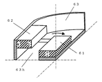
ヨーク63と振動板65に関しては、上述した第5の実施形態と異なる。ヨーク63と振動板65の外形形状はトラック形状である。また、図27および図28に示すように、ヨーク63は、第1のマグネット61の長辺部分の外周側かつ第2のマグネット62に対向した部分が切り欠かれている。つまり、ヨーク63には、第2のマグネット62と対向する部分に開口部63hが形成されている。この開口部63hは、第2のマグネット62と対向する部分を少なくとも含む大きさで形成されている。なお、ヨーク63が第1のマグネット61の下面と第2のマグネット62の外周側の磁極面とを磁気的に結合して支持することは上述した第5の実施形態と同様である。しかし、図28に示すように、第5の実施形態では上記開口部63hを流れていた磁束が、第6の実施形態では矢印で示した部分のヨーク63を流れる。このように第6の実施形態と第5の実施形態とでは、磁路が異なる。また図29に示すように振動板65は、ボイスコイル64より外周側部分であるエッジ部がヨーク63形状に合わせて形成されている。つまり、エッジ部の下面にヨーク63が存在しないエッジ部65aは、上面から見て凹形状(開口部63h側に凸形状)を形成する。エッジの下面にヨーク63が存在するエッジ部65bは、上面から見て凸形状(エッジの下面にあるヨーク63側に凹形状)を形成する。なお、当該エッジ部65aおよび65bは、当該エッジ部65aおよび65b以外の振動板65と一体の構成であってもよいし、別体の構成であってもよい。   The yoke 63 and the diaphragm 65 are different from the fifth embodiment described above. The outer shape of the yoke 63 and the diaphragm 65 is a track shape. Further, as shown in FIGS. 27 and 28, the yoke 63 is cut out at the outer peripheral side of the long side portion of the first magnet 61 and the portion facing the second magnet 62. That is, the yoke 63 has an opening 63 h at a portion facing the second magnet 62. The opening 63 h is formed in a size including at least a portion facing the second magnet 62. The yoke 63 magnetically couples and supports the lower surface of the first magnet 61 and the magnetic pole surface on the outer peripheral side of the second magnet 62 as in the fifth embodiment described above. However, as shown in FIG. 28, the magnetic flux flowing through the opening 63h in the fifth embodiment flows through the yoke 63 at the portion indicated by the arrow in the sixth embodiment. Thus, the magnetic path is different between the sixth embodiment and the fifth embodiment. Further, as shown in FIG. 29, the diaphragm 65 has an edge portion, which is an outer peripheral side portion from the voice coil 64, formed in accordance with the shape of the yoke 63. That is, the edge portion 65a in which the yoke 63 does not exist on the lower surface of the edge portion forms a concave shape (a convex shape on the opening 63h side) when viewed from the upper surface. The edge portion 65b in which the yoke 63 is present on the lower surface of the edge forms a convex shape when viewed from the upper surface (concave shape on the yoke 63 side on the lower surface of the edge). The edge portions 65a and 65b may be configured integrally with the diaphragm 65 other than the edge portions 65a and 65b, or may be configured separately.

なお、第6の実施形態に係る動電型電気音響変換器6は、第4の実施形態で説明した動電型電気音響変換器4に対して各構成部の形状が異なるのみであり、動電型電気音響変換器6の動作は動電型電気音響変換器4の動作と同様であるので詳細な説明を省略する。また、第6の実施形態に係る動電型電気音響変換器6は、第4の実施形態と同様の効果が得られる。   The electrodynamic electroacoustic transducer 6 according to the sixth embodiment is different from the electrodynamic electroacoustic transducer 4 described in the fourth embodiment only in the shape of each component. Since the operation of the electric type electroacoustic transducer 6 is the same as that of the electrodynamic type electroacoustic transducer 4, a detailed description thereof will be omitted. Moreover, the electrodynamic electroacoustic transducer 6 according to the sixth embodiment can obtain the same effects as those of the fourth embodiment.

ここで、本実施形態に係る動電型電気音響変換器6の振動方向から見た外形状および振動板65の形状は、トラック形状である。すなわち、動電型電気音響変換器6および振動板65が円形状ではないので、第5の実施形態と同様に空間利用効率が上がる。さらに、第5の実施形態で説明した矩形では角の部分でエッジのスティフネスが高くなってしまうのに対し、第6の実施形態では曲線で構成することで全体のスティフネスをバランス良くすることができる。したがって、第6の実施形態では、矩形の振動板に比べて角の部分の振動が容易となることで、低音域での歪みが少ない電気音響変換器が実現される。   Here, the outer shape and the shape of the diaphragm 65 viewed from the vibration direction of the electrodynamic electroacoustic transducer 6 according to the present embodiment are track shapes. That is, since the electrodynamic electroacoustic transducer 6 and the diaphragm 65 are not circular, the space utilization efficiency increases as in the fifth embodiment. Further, in the rectangle described in the fifth embodiment, the stiffness of the edge becomes high at the corner portion, whereas in the sixth embodiment, the overall stiffness can be improved by forming the curve. . Therefore, in the sixth embodiment, the electroacoustic transducer with less distortion in the low sound range is realized by facilitating the vibration of the corner portion as compared with the rectangular diaphragm.

さらに第6の実施形態では、第2のマグネット62に対向する部分のヨーク63を切り欠き、対向する第2のマグネット62のない部分のヨーク63は切り欠かず、磁路の一部となっている。またそれに対応して、振動板65の短径側のエッジは振動方向に凹型形状、長径側のエッジは凸型形状とし、それぞれ第2のマグネット62とヨーク63に接触しない構成になっている。その結果、第2のマグネット62をヨーク63の厚み分、下方向に設けることができるため、第1のマグネット61と第2のマグネット62の距離が近くなり、磁気ギャップ67に発生する磁束密度が大きくなる。したがって薄型でも高能率な電気音響変換器が可能になる。   Furthermore, in the sixth embodiment, a portion of the yoke 63 that faces the second magnet 62 is cut out, and a portion of the yoke 63 that does not have the facing second magnet 62 is not cut out and becomes a part of the magnetic path. Yes. Correspondingly, the edge on the short diameter side of the diaphragm 65 has a concave shape in the vibration direction, and the edge on the long diameter side has a convex shape so as not to contact the second magnet 62 and the yoke 63, respectively. As a result, since the second magnet 62 can be provided downward by the thickness of the yoke 63, the distance between the first magnet 61 and the second magnet 62 is reduced, and the magnetic flux density generated in the magnetic gap 67 is reduced. growing. Therefore, a highly efficient electroacoustic transducer can be achieved even if it is thin.

なお、第6の実施形態では、第1のマグネット61の上面と第2のマグネット62の下面が、同平面上に位置していたが、どちらかが前面方向に位置するように設けてもよい。   In the sixth embodiment, the upper surface of the first magnet 61 and the lower surface of the second magnet 62 are located on the same plane, but one may be provided so as to be located in the front direction. .

また、第4の実施形態と同様に、第1のマグネット61の上面に第1のプレートを、第2のマグネット62の内周側の磁極面に第2のプレートを設けてもよい。プレートを設けることにより、磁束を集中させることができ、より最適な位置にボイスコイルを設けることができる。その場合、目標とする電気音響変換器の厚みや能率によって、片方のマグネットのみにプレートを設けてもよい。   Further, similarly to the fourth embodiment, a first plate may be provided on the upper surface of the first magnet 61 and a second plate may be provided on the magnetic pole surface on the inner peripheral side of the second magnet 62. By providing the plate, the magnetic flux can be concentrated and the voice coil can be provided at a more optimal position. In that case, a plate may be provided only on one of the magnets depending on the thickness and efficiency of the target electroacoustic transducer.

また、1つの直方体形状のマグネットを第1のマグネット61に用いたが、中央部に空間を設けるように2つの直方体形状マグネットで構成してもよい。第1のマグネット61の下部にあるヨーク63の同位置に貫通孔を設けることで、振動板の下側の空気を抜きやすくなる。   In addition, although one cuboid-shaped magnet is used for the first magnet 61, it may be composed of two cuboid-shaped magnets so as to provide a space in the center. Providing a through hole at the same position of the yoke 63 below the first magnet 61 makes it easier to vent air below the diaphragm.

また、ボイスコイルの形状を矩形形状としたが、振動板形状と同様にトラック形状でもよい。   Moreover, although the shape of the voice coil is a rectangular shape, it may be a track shape like the diaphragm shape.

(第7の実施形態)
図30〜図32を参照して、本発明の第7の実施形態に係る動電型電気音響変換器7について説明する。図30は、第7の実施形態に係る動電型電気音響変換器7の構造断面図である。図31および図32については、後述にて説明する。図30において、動電型電気音響変換器7は、第1の磁極11、第2の磁極12、ヨーク73、ボイスコイル14、および振動板15を備える。ここで、第1の磁極11、第2の磁極12、ボイスコイル14、および振動板15は、上述した第1の実施形態の各構成部と同様であり、同じ符号を付して説明を省略する。
(Seventh embodiment)
With reference to FIGS. 30 to 32, an electrodynamic electroacoustic transducer 7 according to a seventh embodiment of the present invention will be described. FIG. 30 is a structural cross-sectional view of the electrodynamic electroacoustic transducer 7 according to the seventh embodiment. 31 and 32 will be described later. 30, the electrodynamic electroacoustic transducer 7 includes a first magnetic pole 11, a second magnetic pole 12, a yoke 73, a voice coil 14, and a diaphragm 15. Here, the first magnetic pole 11, the second magnetic pole 12, the voice coil 14, and the diaphragm 15 are the same as the respective components of the first embodiment described above, and the same reference numerals are given and description thereof is omitted. To do.

動電型電気音響変換器7は、図30に示すように、上述した動電型電気音響変換器1に対して、ヨークの構造が異なる変換器である。具体的には、ヨーク73は、第2の磁極12が固着されている部分において、第2の磁極12の内径より内側に張り出した構造となる。つまり、動電型電気音響変換器7の前面側に形成される音孔は、ヨーク73によって、第1の実施形態よりも小さい内径を有する音孔となる。ただし、このような構造は、第2の磁極12の厚さが十分厚く、振動板15がヨーク73の張り出し部分に接触するよりも先に第2の磁極12に接触するような場合にとり得る構造である。   As shown in FIG. 30, the electrodynamic electroacoustic transducer 7 is a transducer having a yoke structure different from that of the electrodynamic electroacoustic transducer 1 described above. Specifically, the yoke 73 has a structure projecting inward from the inner diameter of the second magnetic pole 12 in the portion where the second magnetic pole 12 is fixed. That is, the sound hole formed on the front surface side of the electrodynamic electroacoustic transducer 7 becomes a sound hole having an inner diameter smaller than that of the first embodiment by the yoke 73. However, such a structure can be taken when the thickness of the second magnetic pole 12 is sufficiently thick and the diaphragm 15 contacts the second magnetic pole 12 before contacting the protruding portion of the yoke 73. It is.

第1の磁極11および第2の磁極12間の磁束の流れは、図31の矢印で示されるような流れとなる。図31は、本実施形態における磁気回路の一例を有限要素法によって磁場解析して、磁束の流れをベクトルによって表した図である。また、ボイスコイル位置での磁束密度を動電型電気音響変換器1と動電型電気音響変換器7とで比較すると、図32に示すようになる。図32は、動電型電気音響変換器1および動電型電気音響変換器7の各ボイスコイル位置での磁束密度をそれぞれ曲線で示した図である。つまり、図32は、ヨークの張り出しが有るとき(ヨーク73を使用する動電型電気音響変換器7)と、ヨークの張り出しが無いとき(ヨーク13を使用する動電型電気音響変換器1)とで、ボイスコイル位置での磁束密度を比較した図である。   The flow of magnetic flux between the first magnetic pole 11 and the second magnetic pole 12 is as shown by the arrows in FIG. FIG. 31 is a diagram in which an example of a magnetic circuit according to the present embodiment is subjected to magnetic field analysis by a finite element method, and the flow of magnetic flux is represented by a vector. Further, when the magnetic flux density at the voice coil position is compared between the electrodynamic electroacoustic transducer 1 and the electrodynamic electroacoustic transducer 7, it is as shown in FIG. FIG. 32 is a diagram showing the magnetic flux densities at the respective voice coil positions of the electrodynamic electroacoustic transducer 1 and the electrodynamic electroacoustic transducer 7 by curves. That is, FIG. 32 shows the case where the yoke is overhanging (electrokinetic electroacoustic transducer 7 using the yoke 73) and the case where there is no yoke overhanging (electrokinetic electroacoustic transducer 1 using the yoke 13). It is the figure which compared the magnetic flux density in a voice coil position.

図32に示すように、張り出しが有るときの方がボイスコイル位置における磁束密度が大きくなり、張り出しが無いときよりも大きな駆動力が得られる。つまり、動電型電気音響変換器1の構造よりも動電型電気音響変換器7の構造の方が、大きな駆動力を得ることが可能である。   As shown in FIG. 32, when there is an overhang, the magnetic flux density at the voice coil position increases, and a greater driving force can be obtained than when there is no overhang. That is, the structure of the electrodynamic electroacoustic transducer 7 can obtain a larger driving force than the structure of the electrodynamic electroacoustic transducer 1.

また、ヨーク73の張り出し部分を設けることで、第1の磁極11と当該第1の磁極11が固着された部分のヨーク73とで構成される磁気回路と、第2の磁極12と当該第2の磁極12が固着された部分のヨーク73とで構成される磁気回路とは、ボイスコイル14を基準として上下対称に近い構成となる。これにより、図32に示したように、張り出しが有るときの磁束密度曲線は、張り出しが無いときの曲線に比べて、振幅0の軸に対して、より線対称に近い曲線となる。その結果、動電型電気音響変換器7は、動電型電気音響変換器1よりも再生音の歪を低減させることができる。   In addition, by providing a protruding portion of the yoke 73, a magnetic circuit including the first magnetic pole 11 and the yoke 73 of the portion to which the first magnetic pole 11 is fixed, the second magnetic pole 12, and the second magnetic pole 11 are provided. The magnetic circuit constituted by the yoke 73 of the portion to which the magnetic pole 12 is fixed has a configuration close to vertical symmetry with the voice coil 14 as a reference. As a result, as shown in FIG. 32, the magnetic flux density curve when there is an overhang is a curve that is closer to line symmetry with respect to the axis of amplitude 0 than the curve when there is no overhang. As a result, the electrodynamic electroacoustic transducer 7 can reduce the distortion of the reproduced sound more than the electrodynamic electroacoustic transducer 1.

なお、上述した第1〜第7の実施形態における振動板(15、25、35、45、55、および65)は、当該振動板とボイスコイル(14、24、34、44、54、および64)との固着部分において、例えば図33および図34に示すような形状となる。具体的には、振動板の形状は、第1の磁極の上面と対向する部位がボイスコイルの下端より上方にあり、第2の磁極の下面と対向する部位がボイスコイルの上端より下方にある形状となる。なお、図33は、振動板とボイスコイルとの固着部分における振動板の形状の一例を示す図である。図34は、振動板とボイスコイルとの固着部分における振動板の形状の他の例を示す図である。図33において、ボイスコイル14は、ボイスコイル14の下面が振動板15の上面に配置されるように振動板15に固着される。また図34においては、ボイスコイル14は、ボイスコイル14の上面が振動板15の下面に配置されるように振動板15に固着される。   The diaphragms (15, 25, 35, 45, 55, and 65) in the first to seventh embodiments described above have the diaphragm and voice coils (14, 24, 34, 44, 54, and 64). ), For example, a shape as shown in FIGS. Specifically, the shape of the diaphragm is such that the portion facing the upper surface of the first magnetic pole is above the lower end of the voice coil, and the portion facing the lower surface of the second magnetic pole is below the upper end of the voice coil. It becomes a shape. FIG. 33 is a diagram illustrating an example of the shape of the diaphragm in the fixed portion between the diaphragm and the voice coil. FIG. 34 is a diagram illustrating another example of the shape of the diaphragm in the fixed portion between the diaphragm and the voice coil. In FIG. 33, the voice coil 14 is fixed to the diaphragm 15 so that the lower surface of the voice coil 14 is disposed on the upper surface of the diaphragm 15. In FIG. 34, the voice coil 14 is fixed to the diaphragm 15 so that the upper surface of the voice coil 14 is disposed on the lower surface of the diaphragm 15.

なお、上述した第1〜7の実施形態における振動板(15、25、35、45、55、および65)は、その外周がヨークに固設されるとしたが、これに限定されない。例えば、図35に示すように、ヨーク13には支持体131が固設され、振動板15の外周が当該支持体131に固設される構造であってもよい。図35は、振動板15の外周が支持体131に固設された例を示す図である。なお、支持体は、磁性体で構成されてもよいし、非磁性体で構成されてもよい。   In addition, although the diaphragm (15, 25, 35, 45, 55, and 65) in the first to seventh embodiments described above is fixed to the yoke, it is not limited to this. For example, as shown in FIG. 35, a structure in which a support 131 is fixed to the yoke 13 and the outer periphery of the diaphragm 15 is fixed to the support 131 may be employed. FIG. 35 is a diagram illustrating an example in which the outer periphery of the diaphragm 15 is fixed to the support 131. The support may be made of a magnetic material or a non-magnetic material.

なお、上述した第1〜第7の実施形態に係る動電型電気音響変換器は、モバイル機器、AV機器、または映像機器などの電子機器に搭載して実現することが可能である。モバイル機器としては、例えば携帯電話、PDA(Personal degital assistants)、パーソナルコンピュータ、およびポータブルミュージックプレーヤなど機器が挙げられる。AV機器としては、例えばテレビ、オーディオ、およびカーオーディオなどの機器が挙げられる。映像機器としては、例えばPDP(Plasma display panel)、液晶、またはブラウン管などのテレビが挙げられる。以下、本発明に係る動電型電気音響変換器が携帯電話やPDPなどの薄型テレビにそれぞれ搭載された場合の具体例について説明する。また、カーオーディオとして、本発明に係る動電型電気音響変換器が自動車のドアに搭載された場合の具体例についても説明する。   The electrodynamic electroacoustic transducers according to the first to seventh embodiments described above can be realized by being mounted on an electronic device such as a mobile device, an AV device, or a video device. Examples of the mobile device include a mobile phone, a PDA (Personal Digital Assistant), a personal computer, and a portable music player. Examples of the AV device include devices such as a television, an audio, and a car audio. Examples of the video equipment include a television such as a plasma display panel (PDP), a liquid crystal, or a cathode ray tube. Hereinafter, a specific example in which the electrodynamic electroacoustic transducer according to the present invention is mounted on a thin TV such as a mobile phone or a PDP will be described. Further, a specific example in which the electrodynamic electroacoustic transducer according to the present invention is mounted on a car door as a car audio will be described.

まず、図36を参照して、本発明に係る動電型電気音響変換器が携帯電話80の筐体内部に固設される例について説明する。図36は、携帯電話80に搭載される動電型電気音響変換器1の一例を示す正面図および側面図である。図36においては、例えば上述した動電型電気音響変換器1が携帯電話80の筐体内部に固設されているとする。動電型電気音響変換器1は、携帯電話80の液晶画面の下部にある筐体内部の左右にそれぞれ固設される。   First, an example in which the electrodynamic electroacoustic transducer according to the present invention is fixed inside the housing of the mobile phone 80 will be described with reference to FIG. FIG. 36 is a front view and a side view showing an example of the electrodynamic electroacoustic transducer 1 mounted on the mobile phone 80. In FIG. 36, for example, it is assumed that the above-described electrodynamic electroacoustic transducer 1 is fixed inside the casing of the mobile phone 80. The electrodynamic electroacoustic transducer 1 is fixed to the left and right inside the housing at the lower part of the liquid crystal screen of the mobile phone 80.

ここで、近年、携帯電話等のモバイル機器は薄型化や小型化が求められている。それとともに、筐体内部に搭載される動電型電気音響変換器についても薄型化や小型化が求められている。これに対し、本発明に係る動電型電気音響変換器1は、上述したように、従来と同じ振幅余裕を確保した場合において、従来の動電型電気音響変換器よりも変換器自体の厚みを薄く構成することができる。その結果、本発明に係る動電型電気音響変換器によれば、携帯電話等のモバイル機器に搭載するのに最適な動電型電気音響変換器を提供することができる。   Here, in recent years, mobile devices such as mobile phones are required to be thinner and smaller. At the same time, the electrodynamic electroacoustic transducer mounted inside the housing is also required to be thin and small. On the other hand, as described above, the electrodynamic electroacoustic transducer 1 according to the present invention is thicker than the conventional electrodynamic electroacoustic transducer when the same amplitude margin as that of the conventional electromechanical transducer is secured. Can be made thin. As a result, according to the electrodynamic electroacoustic transducer of the present invention, it is possible to provide an electrodynamic electroacoustic transducer that is optimal for mounting on a mobile device such as a mobile phone.

次に、図37を参照して、本発明に係る動電型電気音響変換器が、薄型化が進むPDPなどの薄型テレビ81の筐体内部に固設される例について説明する。図37は、薄型テレビ81に搭載される動電型電気音響変換器3の一例を示す正面図および薄型テレビ81の一部の内部構造を図示O−A断面で示した側面図である。図37においては、例えば上述した動電型電気音響変換器3が薄型テレビ81の筐体内部に固設されているとする。動電型電気音響変換器3は、薄型テレビ81の筐体内部の左右にそれぞれ固設される。   Next, with reference to FIG. 37, an example will be described in which the electrodynamic electroacoustic transducer according to the present invention is fixed inside the housing of a thin television 81 such as a PDP that is becoming thinner. FIG. 37 is a front view showing an example of the electrodynamic electroacoustic transducer 3 mounted on the flat-screen television 81 and a side view showing a part of the internal structure of the flat-screen television 81 in the OA section. In FIG. 37, for example, it is assumed that the above-described electrodynamic electroacoustic transducer 3 is fixed inside the casing of the thin television 81. The electrodynamic electroacoustic transducer 3 is fixed to the left and right inside the housing of the flat-screen television 81.

ここで、近年、薄型テレビ81などの映像機器は薄型化が求められている。それとともに、筐体内部に搭載される動電型電気音響変換器についても薄型化が求められている。これに対し、本発明に係る動電型電気音響変換器3は、上述したように、従来と同じ振幅余裕を確保した場合において、従来の動電型電気音響変換器よりも変換器自体の厚みを薄く構成することができる。その結果、本発明に係る動電型電気音響変換器によれば、薄型テレビ81などの映像機器に搭載するのに最適な動電型電気音響変換器を提供することができる。   Here, in recent years, video devices such as the thin television 81 are required to be thin. At the same time, the electrodynamic electroacoustic transducer mounted in the housing is also required to be thin. On the other hand, as described above, the electrodynamic electroacoustic transducer 3 according to the present invention is thicker than the conventional electrodynamic electroacoustic transducer when the same amplitude margin as that of the conventional electrodynamic transducer is secured. Can be made thin. As a result, according to the electrodynamic electroacoustic transducer according to the present invention, it is possible to provide an electrodynamic electroacoustic transducer that is optimal for mounting on video equipment such as the flat-screen television 81.

次に、図38を参照して、本発明に係る動電型電気音響変換器が、自動車のドア82の本体部84に固設される例について説明する。図38は、自動車のドア82に搭載される動電型電気音響変換器1の一例を示す図である。図38において、自動車のドア82は、窓部83および本体部84で構成される。そして、例えば上述した動電型電気音響変換器1が本体部84に固設されているとする。本体部84は、内部空間を有する筐体である。   Next, with reference to FIG. 38, an example in which the electrodynamic electroacoustic transducer according to the present invention is fixed to the main body 84 of the door 82 of the automobile will be described. FIG. 38 is a diagram illustrating an example of the electrodynamic electroacoustic transducer 1 mounted on the door 82 of the automobile. In FIG. 38, the door 82 of the automobile includes a window portion 83 and a main body portion 84. For example, it is assumed that the electrodynamic electroacoustic transducer 1 described above is fixed to the main body 84. The main body 84 is a housing having an internal space.

ここで、ドア82の本体部84の内部空間において、動電型電気音響変換器を設置するための空間は非常に狭い空間となる。しかしながら、本発明に係る動電型電気音響変換器1は、上述したように、従来と同じ振幅余裕を確保した場合において、従来の動電型電気音響変換器よりも変換器自体の厚みを薄く構成することができる。その結果、本発明に係る動電型電気音響変換器によれば、自動車のドア82に搭載するのに最適な動電型電気音響変換器を提供することができる。   Here, in the internal space of the main body 84 of the door 82, the space for installing the electrodynamic electroacoustic transducer is a very narrow space. However, as described above, the electrodynamic electroacoustic transducer 1 according to the present invention is thinner in thickness than the conventional electrodynamic electroacoustic transducer when the same amplitude margin as that of the conventional electromechanical electroacoustic transducer is secured. Can be configured. As a result, the electrodynamic electroacoustic transducer according to the present invention can provide an electrodynamic electroacoustic transducer that is optimal for mounting on the door 82 of the automobile.

さらに、自動車は様々な環境下に置かれることから、当該自動車に搭載される電子機器には非常に高い温度信頼性が求められている。これに対し、本発明に係る動電型電気音響変換器は、上述したように従来と同じ厚みで構成した場合において、従来と比べてマグネットの厚みを厚くすることができる。これにより、ネオジウムなどを用いた高エネルギー積マグネットを用いた場合であっても、パーミアンス係数が高くなり、従来よりも高温減磁に強くなる。つまり、本発明に係る動電型電気音響変換器の温度信頼性は従来よりも高く、本発明に係る動電型電気音響変換器は、自動車に搭載される変換器としてより最適な動電型電気音響変換器である。   Furthermore, since automobiles are placed in various environments, extremely high temperature reliability is required for electronic devices mounted on the automobiles. On the other hand, when the electrodynamic electroacoustic transducer according to the present invention is configured with the same thickness as the conventional one as described above, the magnet can be made thicker than the conventional one. As a result, even when a high energy product magnet using neodymium or the like is used, the permeance coefficient is increased and it is more resistant to high temperature demagnetization than in the past. That is, the temperature reliability of the electrodynamic electroacoustic transducer according to the present invention is higher than before, and the electrodynamic electroacoustic transducer according to the present invention is an electrodynamic type that is more optimal as a transducer mounted on an automobile. Electroacoustic transducer.

本発明に係る動電型電気音響変換器は、電気音響変換器を有する全ての電子機器に適用可能であり、特に電気音響変換器の小型化、薄型化が必要とされる携帯電話、PDA等のモバイル機器等に有用である。また、電気音響変換器の形状が細長い矩形形状であることが必要なディスプレイ等にも応用可能である。   The electrodynamic electroacoustic transducer according to the present invention can be applied to all electronic devices having an electroacoustic transducer, and in particular, a cellular phone, a PDA, etc. in which the electroacoustic transducer needs to be reduced in size and thickness. This is useful for mobile devices. Further, the present invention can be applied to a display or the like that requires that the electroacoustic transducer has an elongated rectangular shape.

第1の実施形態に係る動電型電気音響変換器1の構造断面図Cross-sectional view of the structure of the electrodynamic electroacoustic transducer 1 according to the first embodiment 図1の動電型電気音響変換器1の一部を切り取った斜視図The perspective view which cut off some electrodynamic electroacoustic transducers 1 of FIG. 図1の動電型電気音響変換器1における磁気回路の一例を有限要素法によって磁場解析して、磁束の流れをベクトルによって表した図FIG. 1 is a diagram in which an example of a magnetic circuit in the electrodynamic electroacoustic transducer 1 of FIG. 従来例と図1の動電型電気音響変換器1における磁気回路について、ボイスコイル位置での磁束密度の比較を示す図The figure which shows the comparison of the magnetic flux density in a voice coil position about the magnetic circuit in the conventional example and the electrodynamic electroacoustic transducer 1 of FIG. 第1の磁極11の形状を同軸の貫通孔が形成された円柱状で構成し、第1の磁極11の上面より動電型電気音響変換器1の背面側に第2の磁極12の下面を配置した構造断面図The shape of the first magnetic pole 11 is a cylindrical shape with a coaxial through hole formed, and the lower surface of the second magnetic pole 12 is placed on the back side of the electrodynamic electroacoustic transducer 1 from the upper surface of the first magnetic pole 11. Arranged structure cross section 図1の動電型電気音響変換器1において、プレート11bが省略された構造断面図1 is a sectional view of the electrodynamic electroacoustic transducer 1 shown in FIG. 1 in which the plate 11b is omitted. 図6の動電型電気音響変換器1の一部を切り取った斜視図The perspective view which cut off some electrodynamic electroacoustic transducers 1 of FIG. 図1の動電型電気音響変換器1において、プレート12bが省略された構造断面図1 is a sectional view of the electrodynamic electroacoustic transducer 1 shown in FIG. 1 in which the plate 12b is omitted. 図8の動電型電気音響変換器1の一部を切り取った斜視図The perspective view which cut off some electrodynamic electroacoustic transducers 1 of FIG. 図1の動電型電気音響変換器1において、プレート11bおよびプレート12bが省略された構造断面図1 is a sectional view of the electrodynamic electroacoustic transducer 1 shown in FIG. 1 in which the plate 11b and the plate 12b are omitted. 図10の動電型電気音響変換器1の一部を切り取った斜視図The perspective view which cut off a part of electrodynamic electroacoustic transducer 1 of FIG. 第2の実施形態に係る動電型電気音響変換器2の構造断面図Cross-sectional view of the structure of the electrodynamic electroacoustic transducer 2 according to the second embodiment 図12の動電型電気音響変換器2の一部を切り取った斜視図The perspective view which cut off a part of electrodynamic type electroacoustic transducer 2 of FIG. 第1の磁極21の形状が枠状となる構成を示す動電型電気音響変換器2の構造断面図Structural sectional view of the electrodynamic electroacoustic transducer 2 showing a configuration in which the first magnetic pole 21 has a frame shape. 図14の動電型電気音響変換器2の一部を切り取った斜視図The perspective view which cut off a part of electrodynamic electroacoustic transducer 2 of FIG. 第3の実施形態に係る動電型電気音響変換器3の構造断面図Cross-sectional view of the structure of the electrodynamic electroacoustic transducer 3 according to the third embodiment 図16の動電型電気音響変換器3の一部を切り取った斜視図The perspective view which cut off some electrodynamic electroacoustic transducers 3 of FIG. 第1の磁極31を2つの直方体で構成した場合の動電型電気音響変換器3の構造断面図Cross-sectional view of the structure of the electrodynamic electroacoustic transducer 3 when the first magnetic pole 31 is composed of two rectangular parallelepipeds 図18の動電型電気音響変換器3の一部を切り取った斜視図The perspective view which cut off some electrodynamic electroacoustic transducers 3 of FIG. 第4の実施形態に係る動電型電気音響変換器4の平面図The top view of the electrodynamic electroacoustic transducer 4 which concerns on 4th Embodiment 第4の実施形態に係る動電型電気音響変換器4の構造断面図Sectional drawing of structure of electrodynamic electroacoustic transducer 4 according to the fourth embodiment 図21の動電型電気音響変換器4における磁気回路の一例を有限要素法によって磁場解析して、磁束の流れをベクトルによって表した図FIG. 21 is a diagram in which an example of a magnetic circuit in the electrodynamic electroacoustic transducer 4 of FIG. 図21の動電型電気音響変換器4において、プレート48、49が付加され、第1のマグネット41に貫通孔がある場合の構造断面図In the electrodynamic electroacoustic transducer 4 of FIG. 21, a sectional view of the structure when plates 48 and 49 are added and the first magnet 41 has a through hole. 第5の実施形態に係る動電型電気音響変換器5の平面図The top view of the electrodynamic electroacoustic transducer 5 which concerns on 5th Embodiment 第5の実施形態に係る動電型電気音響変換器5の構造断面図Sectional drawing of structure of electrodynamic electroacoustic transducer 5 according to the fifth embodiment 第6の実施形態に係る動電型電気音響変換器6の平面図The top view of the electrodynamic electroacoustic transducer 6 which concerns on 6th Embodiment 第6の実施形態に係る動電型電気音響変換器6の構造断面図Sectional drawing of structure of electrodynamic electroacoustic transducer 6 according to a sixth embodiment 動電型電気音響変換器6における、第1マグネット、第2のマグネットおよびヨークの斜視図The perspective view of the 1st magnet, the 2nd magnet, and the yoke in the electrodynamic electroacoustic transducer 6 動電型電気音響変換器6における振動板の斜視図The perspective view of the diaphragm in the electrodynamic electroacoustic transducer 6 第7の実施形態に係る動電型電気音響変換器7の構造断面図Sectional drawing of structure of electrodynamic electroacoustic transducer 7 according to seventh embodiment 図30の動電型電気音響変換器7における磁気回路の一例を有限要素法によって磁場解析して、磁束の流れをベクトルによって表した図FIG. 30 is a diagram in which an example of a magnetic circuit in the electrodynamic electroacoustic transducer 7 of FIG. 30 is analyzed by a finite element method and the flow of magnetic flux is represented by a vector. 動電型電気音響変換器1および動電型電気音響変換器7の各ボイスコイル位置での磁束密度をそれぞれ曲線で示した図The figure which showed the magnetic flux density in each voice coil position of the electrodynamic electroacoustic transducer 1 and the electrodynamic electroacoustic transducer 7 with the curve, respectively. 振動板とボイスコイルとの固着部分における振動板の形状の一例を示す図The figure which shows an example of the shape of the diaphragm in the adhering part of a diaphragm and a voice coil 振動板とボイスコイルとの固着部分における振動板の形状の他の例を示す図The figure which shows the other example of the shape of the diaphragm in the adhering part of a diaphragm and a voice coil 振動板15の外周が支持体131に固設された例を示す図The figure which shows the example by which the outer periphery of the diaphragm 15 was fixed to the support body 131 携帯電話80に搭載される動電型電気音響変換器1の一例を示す正面図および側面図Front view and side view showing an example of the electrodynamic electroacoustic transducer 1 mounted on the mobile phone 80 薄型テレビ81に搭載される動電型電気音響変換器3の一例を示す正面図および薄型テレビ81の一部の内部構造を図示O−A断面で示した側面図The front view which shows an example of the electrodynamic electroacoustic transducer 3 mounted in the thin television 81, and the side view which showed the internal structure of a part of thin television 81 in illustration OA cross section 自動車のドア82に搭載される動電型電気音響変換器1の一例を示す図The figure which shows an example of the electrodynamic electroacoustic transducer 1 mounted in the door 82 of a motor vehicle 従来における動電型電気音響変換器200の構造断面図Cross-sectional view of structure of conventional electrodynamic electroacoustic transducer 200 従来における電磁誘導型電気音響変換器300の構造断面図Cross-sectional view of a conventional electromagnetic induction type electroacoustic transducer 300

符号の説明Explanation of symbols

1、2、3、4、5、6、7 動電型電気音響変換器
11、21、31 第1の磁極
11a、12a、21a、22a、31a、31c、32a、32c マグネット
11b、12b、21b、22b、31b、31d、32b、32d プレート
12、22、32 第2の磁極
13、23、33、43、53、63、73 ヨーク
14、24、34、44、54、64 ボイスコイル
15、25、35、45、55、65 振動板
15a、25a、35a、45a、55a、65a、65b エッジ部
41、51、61 第1のマグネット
42、52、62 第2のマグネット
80 携帯電話
81 薄型テレビ
82 ドア
83 窓部
84 本体部

1, 2, 3, 4, 5, 6, 7 Electrodynamic electroacoustic transducers 11, 21, 31 First magnetic poles 11a, 12a, 21a, 22a, 31a, 31c, 32a, 32c Magnets 11b, 12b, 21b 22b, 31b, 31d, 32b, 32d Plates 12, 22, 32 Second magnetic poles 13, 23, 33, 43, 53, 63, 73 Yoke 14, 24, 34, 44, 54, 64 Voice coils 15, 25 , 35, 45, 55, 65 Diaphragm
15a, 25a, 35a, 45a, 55a, 65a, 65b Edge portions 41, 51, 61 First magnet 42, 52, 62 Second magnet 80 Mobile phone 81 Flat-screen TV 82 Door 83 Window portion 84 Body portion

Claims (5)

少なくとも1つのマグネットで形成される第1の磁極部と、
マグネットをそれぞれに含む少なくとも1つの立体で形成され、前記第1の磁極部との間に磁気ギャップを形成して前記第1の磁極部の上面および下面方向の空間を除いた空間に配置される第2の磁極部と、
前記第1の磁極部の下面と前記第2の磁極部の前記磁気ギャップとは反対側に位置する側面とを磁気的に結合して支持するヨークと、
前記第1の磁極部における上面方向の空間および前記第2の磁極部における下面方向の空間内に配置され、前記ヨークにその外周が全周に渡って支持された上下方向に振動可能な振動板と、
前記振動板に固着され、前記磁気ギャップ内に配置されるボイスコイルとを備え、
前記ボイスコイルは、その内周形状が前記第1の磁極部の外周形状より大きく、
前記第2の磁極部は、前記第1の磁極部および前記ボイスコイルの上面および下面方向の空間を除いた空間に配置され、
前記第1の磁極部に含まれるマグネットは振動板の振動方向に着磁され、
前記第2の磁極部に含まれるマグネットは振動板の振動方向に対して垂直な方向に、前記磁気ギャップ側が第1の磁極部上面の極と反対の極になるように着磁され、
前記第1の磁極部および前記第2の磁極部は、前記磁気ギャップ内において、前記ボイスコイルの内部に前記振動板の振動方向に対して略垂直方向の磁束を生成し、
前記振動板の振動方向における前記ボイスコイルの厚みの中心は、当該振動方向におけ
る前記第1の磁極部の厚みの中心と、当該振動方向における前記第2の磁極部の厚みの中
心との間に位置し、
前記振動板は、当該振動板を振動可能にするエッジ部を含み、前記エッジ部の少なくとも一部が前記第2の磁極部の下面と対向することを特徴とする、動電型電気音響変換器。
A first magnetic pole portion formed in at least one the magnet bets,
It is formed in at least one three- dimensional body including magnets, and is disposed in a space excluding the space in the upper and lower surface directions of the first magnetic pole portion by forming a magnetic gap with the first magnetic pole portion. A second magnetic pole part,
A yoke that magnetically couples and supports a lower surface of the first magnetic pole part and a side surface of the second magnetic pole part located on the opposite side of the magnetic gap;
A diaphragm that is disposed in a space in the upper surface direction of the first magnetic pole portion and in a space in the lower surface direction of the second magnetic pole portion, and whose outer periphery is supported by the yoke over the entire circumference and can vibrate in the vertical direction. When,
A voice coil fixed to the diaphragm and disposed in the magnetic gap;
The voice coil has an inner peripheral shape larger than an outer peripheral shape of the first magnetic pole portion,
The second magnetic pole part is disposed in a space excluding the first magnetic pole part and the space in the upper and lower surface directions of the voice coil,
The magnet included in the first magnetic pole portion is magnetized in the vibration direction of the diaphragm,
The magnet included in the second magnetic pole part is magnetized in a direction perpendicular to the vibration direction of the diaphragm so that the magnetic gap side is a pole opposite to the pole on the upper surface of the first magnetic pole part,
The first magnetic pole part and the second magnetic pole part generate a magnetic flux substantially perpendicular to the vibration direction of the diaphragm in the voice coil within the magnetic gap,
The center of the thickness of the voice coil in the vibration direction of the diaphragm is in the vibration direction.
Of the thickness of the first magnetic pole part and the thickness of the second magnetic pole part in the vibration direction.
Located between the heart,
The diaphragm includes an edge portion that enables the diaphragm to vibrate, and at least a part of the edge portion faces a lower surface of the second magnetic pole portion, and the electrodynamic electroacoustic transducer .
前記振動板は、前記第1の磁極部の上面と対向する部の形状が他の部に対して相対的に凸形状で形成されることを特徴とする、請求項1に記載の動電型電気音響変換器。 The diaphragm is characterized in that the shape of the part position that faces the upper surface of the first magnetic pole portion is formed in a relatively convex with respect to the other parts position, movement of Claim 1 Electric electroacoustic transducer. 前記ボイスコイルは、前記振動板の上面側または下面側のいずれかに固着され、
前記振動板は、前記第1の磁極部の上面と対向する部が前記ボイスコイルの下端より上方にあり、前記第2の磁極部の下面と対向する部が前記ボイスコイルの上端より下方にある形状で形成されることを特徴とする、請求項1または2に記載の動電型電気音響変換器。
The voice coil is fixed to either the upper surface side or the lower surface side of the diaphragm,
The diaphragm, the first top surface and the opposing part position of the magnetic pole portion is located above the lower end of the voice coil, lower than the upper end of the second magnetic pole portion of the lower surface facing the part position is the voice coil 3. The electrodynamic electroacoustic transducer according to claim 1 or 2 , wherein the electrodynamic electroacoustic transducer is formed in a certain shape.
前記第1の磁極部および前記第2の磁極部は、その中央に空隙が形成された環状体であり、The first magnetic pole part and the second magnetic pole part are annular bodies having a gap formed at the center thereof,
前記第1の磁極部は、前記第2の磁極部を構成する環状体空隙の上下方向空間内に配置されることを特徴とする、請求項1から3のいずれかに記載の動電型電気音響変換器。The electrodynamic electricity according to any one of claims 1 to 3, wherein the first magnetic pole portion is disposed in a vertical space of an annular gap that constitutes the second magnetic pole portion. Acoustic transducer.
請求項1記載の動電型電気音響変換器が搭載された、電子機器。An electronic apparatus on which the electrodynamic electroacoustic transducer according to claim 1 is mounted.
JP2006175737A 2005-01-28 2006-06-26 Electrodynamic electroacoustic transducer and electronic equipment Active JP4783683B2 (en)

Priority Applications (1)

Application Number Priority Date Filing Date Title
JP2006175737A JP4783683B2 (en) 2005-01-28 2006-06-26 Electrodynamic electroacoustic transducer and electronic equipment

Applications Claiming Priority (7)

Application Number Priority Date Filing Date Title
JP2005021405 2005-01-28
JP2005225016 2005-08-03
JP2005262634 2005-09-09
JP2006175737A JP4783683B2 (en) 2005-01-28 2006-06-26 Electrodynamic electroacoustic transducer and electronic equipment

Related Parent Applications (1)

Application Number Title Priority Date Filing Date
JP2006017992A Division JP3841222B1 (en) 2005-01-28 2006-01-26 Electrodynamic electroacoustic transducer and electronic equipment

Publications (3)

Publication Number Publication Date
JP2007104634A JP2007104634A (en) 2007-04-19
JP2007104634A5 JP2007104634A5 (en) 2009-01-22
JP4783683B2 true JP4783683B2 (en) 2011-09-28

Family

ID=38031072

Family Applications (1)

Application Number Title Priority Date Filing Date
JP2006175737A Active JP4783683B2 (en) 2005-01-28 2006-06-26 Electrodynamic electroacoustic transducer and electronic equipment

Country Status (1)

Country Link
JP (1) JP4783683B2 (en)

Families Citing this family (3)

* Cited by examiner, † Cited by third party
Publication number Priority date Publication date Assignee Title
DK2656636T3 (en) 2010-12-23 2022-05-02 Eagle Acoustics Mfg Llc Low profile speaker
US10999682B2 (en) 2017-10-25 2021-05-04 Ps Audio Design Oy Transducer arrangement
CN108401213B (en) * 2018-03-30 2024-03-01 东莞涌韵音膜有限公司 Electroacoustic unit using memory alloy wire to drive vibrating diaphragm

Also Published As

Publication number Publication date
JP2007104634A (en) 2007-04-19

Similar Documents

Publication Publication Date Title
JP3841222B1 (en) Electrodynamic electroacoustic transducer and electronic equipment
EP1843630B1 (en) Electrodynamic electroacoustic transducer and electronic device
JP2008516518A (en) Magnetic circuit with double magnet, speaker and vibration generator using the same
JP5100546B2 (en) Electroacoustic transducer
US8131002B2 (en) Electric-acoustic transducer and electronic device
JP2009225091A (en) Exciter and speaker
JP4783683B2 (en) Electrodynamic electroacoustic transducer and electronic equipment
US20120308070A1 (en) Slim type speaker and magnetic circuit therefor
KR20090127379A (en) Speaker and electronic apparatus using the same
JP2009267779A (en) Electromagnetic electro-acoustic transducer
JP4087878B2 (en) Electrodynamic electroacoustic transducer and electronic equipment
JP4600024B2 (en) Speaker and method for manufacturing the speaker
JP4814361B2 (en) Speaker unit
JP2009049762A (en) Magnetic circuit for speaker, and speaker device
JP2007300297A (en) Magnetic circuit for loudspeaker device, and loudspeaker device
JP2009094914A (en) Speaker
KR19990041872A (en) Speaker structure with double voice coil
US11812248B2 (en) Moving-magnet motor
JP2009094915A (en) Speaker
JP2009260577A (en) Loudspeaker using voice coil assembly, and manufacturing method thereof
JPH11155193A (en) Magnetic field part and loudspeaker using the same
JP2008092042A (en) Electrodynamic type electric acoustic transducer
CN114640931A (en) Loudspeaker
Merit et al. Enhanced construction of the direct radiator electrodynamic loudspeaker
JP2002300694A (en) Repulsive magnetic circuit structure and speaker

Legal Events

Date Code Title Description
A521 Written amendment

Free format text: JAPANESE INTERMEDIATE CODE: A523

Effective date: 20081202

A621 Written request for application examination

Free format text: JAPANESE INTERMEDIATE CODE: A621

Effective date: 20081202

TRDD Decision of grant or rejection written
A01 Written decision to grant a patent or to grant a registration (utility model)

Free format text: JAPANESE INTERMEDIATE CODE: A01

Effective date: 20110621

A01 Written decision to grant a patent or to grant a registration (utility model)

Free format text: JAPANESE INTERMEDIATE CODE: A01

A61 First payment of annual fees (during grant procedure)

Free format text: JAPANESE INTERMEDIATE CODE: A61

Effective date: 20110711

FPAY Renewal fee payment (event date is renewal date of database)

Free format text: PAYMENT UNTIL: 20140715

Year of fee payment: 3

R150 Certificate of patent or registration of utility model

Ref document number: 4783683

Country of ref document: JP

Free format text: JAPANESE INTERMEDIATE CODE: R150

Free format text: JAPANESE INTERMEDIATE CODE: R150