JP4781772B2 - Lens barrel - Google Patents
Lens barrel Download PDFInfo
- Publication number
- JP4781772B2 JP4781772B2 JP2005296709A JP2005296709A JP4781772B2 JP 4781772 B2 JP4781772 B2 JP 4781772B2 JP 2005296709 A JP2005296709 A JP 2005296709A JP 2005296709 A JP2005296709 A JP 2005296709A JP 4781772 B2 JP4781772 B2 JP 4781772B2
- Authority
- JP
- Japan
- Prior art keywords
- lens
- drive motor
- guide shaft
- optical axis
- lens barrel
- Prior art date
- Legal status (The legal status is an assumption and is not a legal conclusion. Google has not performed a legal analysis and makes no representation as to the accuracy of the status listed.)
- Expired - Fee Related
Links
Images


Landscapes
- Lens Barrels (AREA)
Description
本発明は、光軸方向に配列された複数枚のレンズを移動させることによって、ズーム倍率を変更する機能を備えたレンズ鏡筒に関するものである。 The present invention relates to a lens barrel having a function of changing a zoom magnification by moving a plurality of lenses arranged in an optical axis direction.
近年、光学系によって結像された被写体像を撮像する撮像素子を備えたデジタルカメラが一般に普及している。このデジタルカメラでは、レンズを移動させることによって、撮像素子にて得られる画像信号から合焦位置を特定する、所謂オートフォーカス機能を備えていることが一般的である。このようなオートフォーカス機能を備えたデジタルカメラでは、レンズを保持したレンズ保持枠と、このレンズ保持枠の移動方向を光軸方向にガイドするガイド軸を備えたレンズ移動装置が組み込まれている(特許文献1)。このオートフォーカス機能が有効となると例えば駆動モータ等の駆動源が駆動し、その駆動力がレンズ保持枠に伝達されることによってレンズ保持枠が光軸方向に微小移動される。 In recent years, digital cameras equipped with an image sensor that captures a subject image formed by an optical system have become popular. In general, this digital camera has a so-called autofocus function for specifying a focus position from an image signal obtained by an image sensor by moving a lens. A digital camera equipped with such an autofocus function incorporates a lens moving device having a lens holding frame that holds a lens and a guide shaft that guides the moving direction of the lens holding frame in the optical axis direction ( Patent Document 1). When this autofocus function is activated, a driving source such as a driving motor is driven, and the driving force is transmitted to the lens holding frame, whereby the lens holding frame is moved minutely in the optical axis direction.
最近では、ズーム倍率を変更することができる、所謂光学ズーム機能を備えたデジタルカメラが一般的に普及している。この光学ズーム機能を備えた場合、上述したレンズ移動装置が光軸方向に複数配列され、これらレンズ装置のうち、上流側のレンズ移動装置によってズーム倍率の変更を行い、また、下流側のレンズ移動装置によってフォーカス調整が行われることが一般的である。
しかしながら、フォーカス調整と、ズーム倍率とのそれぞれを、複数のレンズ移動装置のいずれかで行う場合、駆動モータの位置によっては、レンズ鏡筒自体が大きくなり、近年におけるカメラ本体の小型化、或いは薄型化に逆行することになる。このため、それぞれの駆動モータの駆動軸を向け合うように駆動モータを配置することで、このような欠点を解消することができるが、それぞれの駆動モータと、カメラの制御装置とを電気的に接続するフレキシブル回路基板を、それぞれの駆動モータに対して配線する必要があるため、フレキシブル回路基板の形状が複雑であり、また基板面積が大きくなるという問題がある。 However, when each of the focus adjustment and the zoom magnification is performed by any of a plurality of lens moving devices, the lens barrel itself becomes large depending on the position of the drive motor, and the camera body has recently become smaller or thinner. It goes against the process. For this reason, by arranging the drive motors so that the drive shafts of the respective drive motors face each other, such drawbacks can be solved. However, the respective drive motors and the camera control device are electrically connected. Since it is necessary to wire the flexible circuit board to be connected to each drive motor, there is a problem that the shape of the flexible circuit board is complicated and the board area becomes large.
本発明は、上記課題を解決するためになされたものであり、駆動モータ等のアクチュエータの配置によって、フレキシブル基板の形状を簡易な形状で、且つ基板面積を小さくすることができるようにしたレンズ鏡筒を提供するものである。 The present invention has been made in order to solve the above-described problems, and a lens mirror in which the shape of a flexible substrate can be simplified and the substrate area can be reduced by arranging actuators such as a drive motor. A tube is provided.
本発明のレンズ鏡筒は、レンズを保持するレンズキャリアと、前記レンズキャリアの移動方向を、入射光の光軸方向にガイドするガイド軸と、前記ガイド軸が挿通され、アクチュエータの駆動により前記レンズキャリアを前記光軸方向に移動させる駆動伝達部材とを備えたレンズ移動装置がシャッタ装置の上流側、及び下流側に配置された状態で、鏡筒本体の内部に収納されるレンズ鏡筒であって、前記シャッタ装置に対して上流側となるレンズ移動装置を駆動するアクチュエータを、前記駆動伝達部材に挿通されるガイド軸と前記鏡筒本体の内面との間で、かつ前記シャッタ装置の上面近傍に、前記シャッタ装置に対して下流側となるレンズ移動装置を駆動するアクチュエータを、前記前記駆動伝達部材に挿通されるガイド軸と前記シャッタ装置のアクチュエータが収納される収納部との間で、かつ前記シャッタ装置の下面近傍に、それぞれ配置したことを特徴とする。なお、上流側に配置されるレンズキャリアは、被写体側に配置されるレンズキャリアを示し、下流側に配置されるレンズキャリアは、CCD等の撮像素子側に配置されるレンズキャリアを示すものとする。 The lens barrel of the present invention includes a lens carrier that holds a lens, a guide shaft that guides the moving direction of the lens carrier in an optical axis direction of incident light, and the guide shaft that is inserted, and the lens is driven by an actuator. A lens barrel that is housed inside the barrel body in a state in which a lens moving device including a drive transmission member that moves the carrier in the optical axis direction is disposed on the upstream side and the downstream side of the shutter device. And an actuator for driving the lens moving device on the upstream side with respect to the shutter device, between the guide shaft inserted through the drive transmission member and the inner surface of the barrel main body, and in the vicinity of the upper surface of the shutter device. Further, an actuator for driving the lens moving device on the downstream side with respect to the shutter device is provided with a guide shaft inserted through the drive transmission member and the shutter. Between the housing part actuator device is housed, and near the bottom of the shutter device, characterized in that arranged, respectively. The lens carrier disposed on the upstream side indicates a lens carrier disposed on the subject side, and the lens carrier disposed on the downstream side indicates a lens carrier disposed on the imaging element side such as a CCD. .
また、前記鏡筒本体は、前記光軸方向と直交する面、及び光軸方向を含む面のそれぞれと直交する第1内壁面と、前記光軸方向と直交する面、及び前記第1内壁面のそれぞれと直交する第2内壁面とを備えた略箱形状から構成し、前記収納部を前記第1内壁面に連なって設けるとともに、前記シャッタ装置に対して上流側となるレンズ移動装置を駆動するアクチュエータを、前記第1内壁面と前記駆動伝達部材に挿通されるガイド軸との間に配置し、前記鏡筒本体に配置されるレンズ移動装置を駆動するアクチュエータの端子、及びシャッタ装置のアクチュエータの端子を前記第2内壁面から、それぞれ鏡筒本体の外部に突出させることを特徴とする。 The lens barrel body includes a first inner wall surface orthogonal to each of a surface orthogonal to the optical axis direction and a surface including the optical axis direction, a surface orthogonal to the optical axis direction, and the first inner wall surface. And a second inner wall surface orthogonal to each of the first and second inner wall surfaces, the storage portion being provided continuously to the first inner wall surface, and driving a lens moving device upstream of the shutter device. And an actuator terminal for driving a lens moving device disposed in the lens barrel body, and an actuator for a shutter device. The actuator is disposed between the first inner wall surface and a guide shaft inserted through the drive transmission member. The terminals are respectively projected from the second inner wall surface to the outside of the lens barrel body.
この場合、前記レンズキャリアの位置をそれぞれ検知する検知装置を備え、これら検知装置を、前記駆動伝達部材に挿通されるガイド軸と前記第2内壁面との間にそれぞれ配置し、これら検知装置の端子を第2内壁面から外部に突出させることが好ましい。 In this case, a detection device that detects the position of each of the lens carriers is provided, and these detection devices are arranged between the guide shaft inserted through the drive transmission member and the second inner wall surface, respectively. It is preferable to project the terminal from the second inner wall surface to the outside.
また、前記鏡筒本体は略筒形状から構成されており、前記レンズ移動装置を駆動するアクチュエータの端子、及びシャッタ装置のアクチュエータの端子を、それぞれ前記鏡筒本体の内周面から、鏡筒本体の外部に突出させることを特徴とする。 Further, the lens barrel body is formed in a substantially cylindrical shape, and the terminal of the actuator that drives the lens moving device and the terminal of the actuator of the shutter device are respectively connected from the inner peripheral surface of the lens barrel body to the lens barrel body. It is characterized by projecting to the outside.
この場合、前記レンズキャリアの位置をそれぞれ検知する検知装置を備え、これら検知装置を、前記駆動伝達部材に挿通されるガイド軸と前記内周面との間にそれぞれ配置し、前記検知装置の端子を前記内周面から鏡筒本体の外部に突出させることが好ましい。 In this case, a detection device that detects the position of each of the lens carriers is provided, and these detection devices are arranged between the guide shaft inserted through the drive transmission member and the inner peripheral surface, respectively, and terminals of the detection device It is preferable to protrude from the inner peripheral surface to the outside of the barrel main body.
本発明のレンズ鏡筒によれば、レンズを保持するレンズキャリアと、前記レンズキャリアの移動方向を、入射光の光軸方向にガイドするガイド軸と、前記ガイド軸が挿通され、アクチュエータの駆動により前記レンズキャリアを前記光軸方向に移動させる駆動伝達部材とを備えたレンズ移動装置がシャッタ装置の上流側、及び下流側に配置された状態で、鏡筒本体の内部に収納されるレンズ鏡筒であって、前記シャッタ装置に対して上流側となるレンズ移動装置を駆動するアクチュエータを、前記駆動伝達部材に挿通されるガイド軸と前記鏡筒本体の内面との間で、かつ前記シャッタ装置の上面近傍に、前記シャッタ装置に対して下流側となるレンズ移動装置を駆動するアクチュエータを、前記前記駆動伝達部材に挿通されるガイド軸と前記シャッタ装置のアクチュエータが収納される収納部との間で、かつ前記シャッタ装置の下面近傍に、それぞれ配置したから、例えば、これらアクチュエータを電気的に接続するフレキシブル回路基板等の基板面積を小さくすることができる。 According to the lens barrel of the present invention, the lens carrier that holds the lens, the guide shaft that guides the moving direction of the lens carrier in the optical axis direction of the incident light, and the guide shaft are inserted and driven by the actuator. A lens barrel housed inside the barrel body in a state in which a lens moving device including a drive transmission member for moving the lens carrier in the optical axis direction is disposed on the upstream side and the downstream side of the shutter device. An actuator for driving the lens moving device on the upstream side with respect to the shutter device is provided between the guide shaft inserted through the drive transmission member and the inner surface of the barrel main body, and In the vicinity of the upper surface, an actuator for driving the lens moving device on the downstream side with respect to the shutter device, a guide shaft inserted into the drive transmission member, and the Since the actuator of the shutter device is disposed between the housing unit and the vicinity of the lower surface of the shutter device, for example, the board area of a flexible circuit board or the like that electrically connects these actuators is reduced. Can do.
また、前記鏡筒本体は、前記光軸方向と直交する面、及び光軸方向を含む面のそれぞれと直交する第1内壁面と、前記光軸方向と直交する面、及び前記第1内壁面のそれぞれと直交する第2内壁面とを備えた略箱形状から構成し、前記収納部を前記第1内壁面に連なって設けるとともに、前記シャッタ装置に対して上流側となるレンズ移動装置を駆動するアクチュエータを、前記第1内壁面と前記駆動伝達部材に挿通されるガイド軸との間に配置し、前記鏡筒本体に配置されるレンズ移動装置を駆動するアクチュエータの端子、及びシャッタ装置のアクチュエータの端子を前記第2内壁面から、それぞれ鏡筒本体の外部に突出させるから、これらアクチュエータ用のフレキシブル回路基板等の基板面積を小さくすることができる。さらに、回路基板と、端子との接続面が同一面上とすることが可能であるから、製造工程も簡易にすることができる。 The lens barrel body includes a first inner wall surface orthogonal to each of a surface orthogonal to the optical axis direction and a surface including the optical axis direction, a surface orthogonal to the optical axis direction, and the first inner wall surface. And a second inner wall surface orthogonal to each of the first and second inner wall surfaces, the storage portion being provided continuously to the first inner wall surface, and driving a lens moving device upstream of the shutter device. And an actuator terminal for driving a lens moving device disposed in the lens barrel body, and an actuator for a shutter device. The actuator is disposed between the first inner wall surface and a guide shaft inserted through the drive transmission member. Since the terminals protrude from the second inner wall surface to the outside of the lens barrel body, the area of the flexible circuit board for the actuator can be reduced. Furthermore, since the connection surface of the circuit board and the terminal can be on the same surface, the manufacturing process can be simplified.
この場合、前記レンズキャリアの位置をそれぞれ検知する検知装置を備え、これら検知装置を、前記駆動伝達部材に挿通されるガイド軸と前記第2内壁面との間にそれぞれ配置し、これら検知装置の端子を第2内壁面から外部に突出させるから、例えば、アクチュエータ用のフレキシブル回路基板に検知装置用の回路を組み込むことができるので、複雑な構成の基板面積を作成する必要が無くなり、また、回路基板の基板面積の大きさを抑制することができる。 In this case, a detection device that detects the position of each of the lens carriers is provided, and these detection devices are arranged between the guide shaft inserted through the drive transmission member and the second inner wall surface, respectively. Since the terminal protrudes from the second inner wall surface to the outside, for example, the circuit for the detection device can be incorporated into the flexible circuit board for the actuator, so that it is not necessary to create a board area with a complicated configuration, and the circuit The size of the substrate area of the substrate can be suppressed.
また、前記鏡筒本体は略筒形状から構成されており、前記レンズ移動装置を駆動するアクチュエータの端子、及びシャッタ装置のアクチュエータの端子を、それぞれ前記鏡筒本体の内周面から、鏡筒本体の外部に突出させるから、これらアクチュエータ用のフレキシブル回路基板等の基板面積を小さくすることができる。 Further, the lens barrel body is formed in a substantially cylindrical shape, and the terminal of the actuator that drives the lens moving device and the terminal of the actuator of the shutter device are respectively connected from the inner peripheral surface of the lens barrel body to the lens barrel body. Therefore, the area of the substrate such as a flexible circuit board for the actuator can be reduced.
この場合、前記レンズキャリアの位置をそれぞれ検知する検知装置を備え、これら検知装置を、前記駆動伝達部材に挿通されるガイド軸と前記内周面との間にそれぞれ配置し、前記検知装置の端子を前記内周面から鏡筒本体の外部に突出させるから、例えば、アクチュエータ用のフレキシブル回路基板に検知装置用の回路を組み込むことができるので、複雑な構成の基板面積を作成する必要が無くなり、また、回路基板の基板面積の大きさを抑制することができる。 In this case, a detection device that detects the position of each of the lens carriers is provided, and these detection devices are arranged between the guide shaft inserted through the drive transmission member and the inner peripheral surface, respectively, and terminals of the detection device Projecting from the inner peripheral surface to the outside of the lens barrel body, for example, a circuit for a detection device can be incorporated into a flexible circuit board for an actuator, so that it is not necessary to create a board area with a complicated configuration, In addition, the size of the circuit board substrate area can be suppressed.
図1及び図2に示すデジタルカメラ10は、カメラ本体11の前面に、撮影開口12及びストロボ発光部13が設けられており、上面には、電源ボタン14及びシャッタボタン15が設けられている。
The digital camera 10 shown in FIGS. 1 and 2 is provided with a photographing
カメラ本体11の背面には、LCD(Liquid Crystal Display)16、ズーム操作ボタン17、カーソルボタン18、及びモード切替ボタン19が設けられている。モード切替ボタン19は、撮影画像をメモリカードに記録する撮影モードと、メモリカードに記録された画像を再生する再生モードと、各種設定を行うセットアップモードとを切り替える際にユーザによって操作される。
On the back of the
LCD16は、画像再生に使用される他、撮影モード時には、フレーミング用のスルー画を表示する電子ビューファインダとしても機能する。また、LCD16は、セットアップモードに設定された時にメニュー画面を表示する。カーソルボタン18は、このメニュー画面上でのカーソルの移動や、メニュー画面に表示された項目を選択する際に操作される。ズーム操作ボタン17は、ズーム倍率を変更する際に操作される。
In addition to being used for image reproduction, the
図3は、デジタルカメラ2に組み込まれる撮像光学系を示す説明図である。撮像光学系20は、第1レンズ群G1、第2レンズ群G2、第3レンズ群G3、第4レンズ群G4から構成され、また、第1レンズ群G1に直角プリズムを備えた、所謂屈曲光学系から構成されている。 FIG. 3 is an explanatory diagram showing an imaging optical system incorporated in the digital camera 2. The imaging optical system 20 includes a first lens group G1, a second lens group G2, a third lens group G3, and a fourth lens group G4. The so-called bending optical system includes a right-angle prism in the first lens group G1. It consists of a system.
第1レンズ群G1は、第1レンズ25、直角プリズム26、第2レンズ27とから構成されている。第1レンズ25は、撮影開口12の背面側に配置され、被写体光を取り込んで、直角プリズム26の光入射面26aへと出射する。直角プリズム26は第1レンズ25からの被写体光を入射する光入射面26aと、光入射面26aからプリズム内部に入射した光軸L1の被写体光を90°屈曲させて光軸L2の被写体光とする光反射面26bと、光反射面26bで反射された被写体光を出射する光出射面26cとから構成される。第2レンズ27は、直角プリズム26から出射した光軸L2方向の被写体光を、第2レンズ群G2に向けて出射する。
The first lens group G1 includes a
第2レンズ群G2は、後述するレンズキャリア66に保持されており、図3中A方向、或いは図3中B方向に移動させることによって、撮影時のズーム倍率が変更される。なお、詳細は記載しないが、この第2レンズ群G2は、1枚のレンズからでも、複数枚のレンズから構成されていてもよいものとする。第3レンズ群G3は、第2レンズ群G2からの被写体光を、第4レンズ群G4に入射させるために設けられている。
The second lens group G2 is held by a
第4レンズ群G4は、後述するレンズキャリア67に保持されており、図3中C方向、或いは図3中D方向に微小移動させることによって、フォーカス調整が行われる。この第4レンズ群G4から出射した被写体光は、ローパスフィルタ27を透過した後に、CCDイメージセンサ28の結像面で結像される。なお、ローパスフィルタ27は、モアレや擬色の発生を防止するために設けられている。
The fourth lens group G4 is held by a
図4〜図6に示すように、レンズ鏡筒30は、収納箱31と、この収納箱31の開口された部分に組み付けられる前面蓋32とから構成された鏡筒本体33と、ズーム駆動モータ45、フォーカス駆動モータ46、フォトインタラプタ55,56、レンズ移動ユニット65とから構成されている。
As shown in FIGS. 4 to 6, the lens barrel 30 is composed of a barrel body 33 composed of a
収納箱31は、略箱形状からなる基部31aに対して、図5中左方側面の略中央が、基部31aから突出した形状(以下、収納部31b)から構成されている。この収納箱31の基部31aには、ズーム駆動モータ45、フォーカス駆動モータ46やフォトインタラプタ55,56、レンズ移動ユニット65が収納される。なお、上述した収納部31bには、シャッタ装置72の駆動源となるシャッタ駆動モータ92が収納される。
The
この収納箱31の上面には、プリズム26を収納するプリズム収納部34、及び第1レンズ25を保持するレンズ保持部35がそれぞれ設けられている。プリズム収納部34の両側部には、後述するガイド軸70,71の上端部が挿入される挿入溝部36,37が設けられている。
On the upper surface of the
収納箱31の下面には、ローパスフィルタ27や、CCDイメージセンサ28が組み付けられる組付け部38が設けられている。この組付け部38の両側部であって、上述した挿入溝部36,37に対向する位置には、ガイド軸70,71の下端部が挿入される挿入溝部39,40が設けられている。また、この収納箱31には、レール溝部41,42が設けられており、レンズ移動ユニット65を収納箱31に収納する際に、シャッタ装置72を収納箱31の所定位置に位置決めする。
On the lower surface of the
この収納箱31の基部31aの内壁面31d、31eには、後述するレンズキャリア66,67を光軸L2方向に移動させる駆動源となるズーム駆動モータ45、フォーカス駆動モータ46が、それぞれブラケット47,48を介してネジ49等により固定される。なお、ブラケット47を収納箱31に組み付ける場合には、ネジ49は、基部31aの内壁面31dに設けられた開口31f、31gを介して、ブラケット47のネジ孔47a、47bに螺合される。同様に、ブラケット47を収納箱31に組み付ける場合には、ネジ49は、基部31aの内壁面31eに設けられた開口31h、31iを介してネジ孔48a,48bに螺合される。このとき、ズーム駆動モータ45、フォーカス駆動モータ46の端子45a,46aが、基部31aの内壁面31jに設けられた開口51,52にそれぞれ挿通される。なお、符号53は、シャッタ装置72に設けられるシャッタ駆動モータ92の端子92aが挿通される開口である。
On inner wall surfaces 31d and 31e of the
また、この収納箱31には、レンズキャリア66,67の基準位置を検知するためのフォトインタラプタ55,56が収納箱31の内壁面31jに組み付け固定される。例えばフォトインタラプタ55を収納箱31に組み付ける場合、その端子55a〜55dをそれぞれ開口57a〜57dに挿通させた後に、接着剤等によって収納箱31に固定する。同様にして、フォトインタラプタ56を収納箱31に組み付ける場合、その端子56a〜56dをそれぞれ開口58a〜58dに挿通させた後に、接着剤等によって収納箱31に固定する。なお、符号60は開口であり、後述する第3レンズ群G3のレンズホルダ93の位置調整レバー93bが挿通される。
In the
前面蓋32は、収納箱31の開口された部分を遮蔽するために設けられている。この前面蓋32は、収納箱31にネジ61を、収納箱31のネジ穴31k〜31pに螺合させることで組み付けられる。なお、符号32a〜32fは、ネジ61が挿通される開口である。この前面蓋32の上部は、円弧状に切り欠かれており、前面蓋32を収納箱31に組み付けると、この切り欠かれた部分が、レンズ保持部34の周面に当接される。
The
この前面蓋32の上方、或いは下方には、所定の間隔を空けて、ズレ防止片62a〜62dが設けられている。ズレ防止片62a、62bは、収納箱31の軸受け溝部35,36にそれぞれ挿入され、位置決めされたガイド軸70,71の上端の周面にそれぞれ当接し、ガイド軸70,71の位置ズレを防止する。同様にして、ズレ防止片62c、62dは、収納箱31の軸受け溝部38,39に挿入され、位置決めされたガイド軸70の下端の周面にそれぞれ当接し、ガイド軸70,71の下端部の位置ズレを防止する。なお、符号32gは開口であり、この開口32gは、第3レンズ群を保持するレンズホルダの位置調整レバー93aが挿通される。
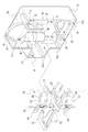
図7は、レンズ移動ユニット65の構成を示す斜視図である。レンズ移動ユニット65は、レンズホルダ66,67、駆動伝達板68,69、ガイド軸70,71、シャッタ装置72から構成される。なお、レンズホルダ66、駆動伝達板68及びガイド軸70,71によって、シャッタ装置72よりも上流側のレンズ移動装置が、レンズホルダ67、駆動伝達板69及びガイド軸70,71によって、シャッタ装置72よりも下流側のレンズ移動装置がそれぞれ構成されている。
FIG. 7 is a perspective view showing the configuration of the
レンズキャリア66は、円筒形状のキャリア本体66aと、ガイド軸70が挿通される軸挿入部66bとから構成される。キャリア本体66aは、第2レンズ群G2を保持するために設けられている。このキャリア本体66aには、ガイド軸71の半径と同一の幅を空けて設けられた支持片73,74が設けられている。これら支持片73,74は、ガイド軸71を挟持し、レンズキャリア66の移動時の位置ズレを防止する。
The
軸挿入部66bは、軸方向の略中央が切り欠かれて形成された空間(以下、収納部75)が設けられ、この収納部75に駆動伝達板68の軸挿通部68aと、圧縮バネ76とが収納される。収納部75に駆動伝達板68の軸挿入部68aと、圧縮バネ76とが収納されることで、駆動伝達板68が収納部75の上壁面に押圧された状態で保持される。この軸挿入部66bに設けられた軸穴77,78には、ガイド軸70が挿通される。また、この軸挿入部66bには、位置検知片79が設けられており、この位置検知片79は、フォトインタラプタ55によって検知することで、レンズキャリア66の位置が把握される。
The
レンズキャリア67は、円筒形状のキャリア本体67aと、ガイド軸70が挿通される軸挿入部67bとから構成されている。キャリア本体67aは、第4レンズ群G4を保持するために設けられている。このキャリア本体67aの外周面からは、ガイド軸71の半径と同一の幅を空けて設けられた支持片80,81とから構成される。これら支持片80,81は、ガイド軸71を挟持するために設けられている。
The
軸挿入部67bは、その光軸方向の略中央が切り欠かれて形成された空間(以下、収納部82)が設けられ、この収納部82に駆動伝達板69の軸挿通部69aと、圧縮バネ83とが収納される。収納部82に駆動伝達板69の軸挿通部69aと、圧縮バネ83とが収納されることで、駆動伝達板69が収納部82の上壁面に押圧された状態で保持される。なお、この軸挿入部67bに設けられた軸穴84,85には、ガイド軸70が挿通される。また、この軸挿入部67bには、位置検知片86が設けられており、この位置検知片86は、フォトインタラプタ56によって検知することで、レンズキャリア67の位置が把握される。
The
駆動伝達板68は、略F字状から構成されている。その一端には、ガイド軸70が挿通される軸挿通部68aが設けられている。この軸挿通部68aの中央には開口86が形成されており、この開口86にガイド軸70が挿通される。駆動伝達板68の他端は、その長手方向に直交するように、支持片68b、68cが所定の間隔を空けて設けられている。この支持片68bと支持片68cとの向かい合う壁面68d,68eには、ラックが形成されており、このラックにズーム駆動モータ45のネジ軸45bが螺合する。
The
駆動伝達板69は、略F字状から構成されている。その一端には、ガイド軸70が挿通される軸挿通部69aが設けられている。この軸挿通部69aの中央には開口87が形成されており、この開口87にガイド軸70が挿通される。駆動伝達板69の他端は、その長手方向に直交するように、支持片69b、69cが所定の間隔を空けて設けられている。この支持片69bと支持片69cとの向かい合う壁面69d,69eには、ラックが形成されており、このラックにフォーカス駆動モータ46のネジ軸46bが螺合する。
The
ガイド軸70,71は、シャッタ装置72に挿通されており、その上端側から、上述したレンズキャリア66が、下端側からレンズキャリア67がそれぞれ組み付けられる。このガイド軸70,71は、レンズキャリア66,67の移動方向を光軸L2方向にガイドする。
The
シャッタ装置72は、詳細は記載しないが、2枚のシャッタ羽根90,91と、シャッタシャッタ駆動モータ92と、シャッタ駆動モータ92の駆動軸に固定されたコマ部材(図示省略)とを備えた構成となっている。このシャッタ装置72のシャッタ駆動モータ92に通電が行われると、コマ部材が回転し、コマ部材に連結された2枚のシャッタ羽根90,91が相反する方向に移動し、これらシャッタ羽根によって形成された露光開口の面積が変化し、絞り値が変化する。また、シャッタボタン15が押圧操作され撮影が行われると、これらシャッタ羽根90,91によって形成された露光開口が一旦遮蔽され、CCDイメージセンサ28への被写体光が遮断される。このとき、CCDイメージセンサ28において、光電変換により得られた電荷が、制御回路基板(図示せず)に向けて出力される。なお、符号93は第3レンズ群G3を保持するレンズホルダである。このレンズホルダ93には、位置調整レバー93a、93bが線対称となるように設けられている。この位置調整レバー93a、93bは、前面蓋32の開口32g、及び収納箱31の開口60から、それぞれ外部に突出する。この位置調整レバー93a、93bは位置調整を行った後に切り取られる。
Although not described in detail, the
次に、本実施形態の作用を説明する。上述したレンズ鏡筒29は、次のようにして作成される。まず、図6に示すように、ブラケット47に組み付けられたズーム駆動モータ45を収納箱31にそれぞれ組み付ける。このとき、ズーム駆動モータ45の端子45aを収納箱31に設けられた開口51に挿通させた後に、ブラケット47を収納箱31にネジ49を用いて固定する。同様にして、ブラケット48に組み付けられたフォーカス駆動モータ46の端子46aを収納箱31の開口52に挿通させた後に、ネジ46を用いてブラケット48を収納箱31に組み付ける。これにより、ズーム駆動モータ45のネジ軸45a,フォーカス駆動モータ46のネジ軸46aが、相反する方向に突出した状態で保持される。
Next, the operation of this embodiment will be described. The
図7に示すように、ズーム駆動モータ45,フォーカス駆動モータ46を組み付けた後に、フォトインタラプタ55,56を収納箱31に組み付ける。例えば、フォトインタラプタ55を組み付ける場合には、その端子45a〜45dを、それぞれ開口57a〜57dに挿通させた後に収納箱31に対して接着固定する。なお、フォトインタラプタ56の組み付けに関しても同様であるから、ここでは、その詳細を省略する。
As shown in FIG. 7, after the
一方、レンズ移動ユニット65は、次のようにして作成される。まず、シャッタ装置72を組み立てたときに、ガイド軸70,71を一体に組み付ける。その後、第2レンズ群G2が保持されたレンズキャリア66をガイド軸70,71の上端側から、第4レンズ群G4が保持されたレンズキャリア67をガイド軸70,71の下端側から、それぞれ組み付ける。例えばレンズキャリア66の軸挿入部66bに設けられた収納部75に、駆動伝達板68の軸挿入部68aと、圧縮バネ76とを収納した状態で、ガイド軸70を軸穴77,78に挿通させる。これにより、駆動伝達板68が、圧縮バネ76の付勢を受けて収納部75の上壁面に当接された状態で保持される。レンズキャリア66についても同様であるので、ここでは、その説明を省略する。その後、シャッタ装置72の上面に、第3レンズ群G3を保持したレンズホルダ93をセットすることで、レンズ移動ユニット65が完成する。
On the other hand, the
図5に示すように、完成したレンズ移動ユニット65は、ズーム駆動モータ45、フォーカス駆動モータ46及びフォトインタラプタ55,56が組み込まれた収納箱31に組み込む。このとき、収納箱31に設けられたレール溝部41に、シャッタ装置72の図5中左方の端部を、レール溝部42に、シャッタ装置72の図5中右方の端部をそれぞれ挿入し、収納箱31の内部に押し込む。このとき、ガイド軸70は、ガイド軸70の上端部が挿入溝部36に、ガイド軸70の下端部が挿入溝部39にそれぞれ挿入される。同時に、ガイド軸71の上端部が挿入溝部37に、ガイド軸70の下端部が挿入溝部40にそれぞれ挿入される。そして、レンズ移動ユニット65を収納箱31の内部に押し込むと、シャッタ装置72のシャッタ駆動モータ92の端子92aが収納箱31に設けられた開口53に挿通される。その後、駆動伝達板68の支持片68b、68cの間にズーム駆動モータ45のネジ軸45bを挿入させ、壁面68d,68eに設けられたラックと、駆動ネジ軸45bとを噛合させる。同様にして、駆動伝達板69の支持片69b、69cの間にフォーカス駆動モータ46のネジ軸46bを挿入させ、壁面69d,69eに設けられたラックと、駆動ネジ軸46bとを噛合させる。
As shown in FIG. 5, the completed
その後、収納箱31の前面から前面蓋32をネジ61等により組み付ける。このとき、レンズホルダ93の位置調整レバー93aが前面蓋32の開口32gから、レンズホルダ93の位置調整レバー93bが収納箱31の開口60から、それぞれ突出する。その後、これら位置調整レバー93a、93bを用いて、第3レンズ群G3の位置調整を行った後、位置調整レバー93a、93bを破断する。なお、開口32g、60は、図示しない蓋によって被覆される。これにより、レンズ鏡筒29が完成する。
Thereafter, the
図9〜図11に示すように、レンズ移動ユニット65が収納箱31に組み込まれると、ズーム駆動モータ45は、ガイド軸70と、収納箱31の内壁面31dとの間に、またシャッタ装置72の上面近傍に保持される。フォーカス駆動モータ46は、ガイド軸70と、収納部31bとの間に、また、シャッタ装置72の下面近傍に保持される。なお、収納部31bにはシャッタ駆動モータ92が収納されるから、シャッタ装置72のシャッタ駆動モータ92の近傍にフォーカス駆動モータ46が保持されることになる。これにより、ズーム駆動モータ45、フォーカス駆動モータ46、シャッタ駆動モータ92が近接して設けられることになる。なお、ズーム駆動モータ45、フォーカス駆動モータ46は、収納箱31の内壁面31jに設けられた開口51,52を介して収納箱31の外部にそれぞれ突出しており、また、シャッタ駆動モータ92も開口53を介して収納箱31の外部に突出しているので、これら端子が略同一平面上に位置することになる。
As shown in FIGS. 9 to 11, when the
また、フォトインタラプタ55,56が、収納箱31の内壁面31jと、ガイド軸70との間にそれぞれ配置されており、また、フォトインタラプタ55の端子55a〜55dが挿通孔57a〜57dを介して、フォトインタラプタの端子が挿通孔58a〜58dを介して、それぞれ収納箱31の外部に突出しているから、これら端子も同一平面上に位置することになる。さらに、位置検知片79がレンズキャリア66の軸挿入部66bに、位置検知片86がレンズキャリア67の軸挿入部67bにそれぞれ設けられていることより、フォトインタラプタ55がズーム駆動モータ45の近傍に、フォトインタラプタ56がフォーカス駆動モータの近傍にそれぞれ配置されているので、フォトインタラプタの端子が、駆動モータの端子の近傍に位置することになる。
Further, the
図12に示すように、完成したレンズ鏡筒29には、ズーム駆動モータ45、フォーカス駆動モータ46,シャッタ駆動モータ92をそれぞれ駆動制御するための回路を備えたフレキシブル回路基板100が組み付けられる。なお、この際、レンズ鏡筒29の後面から突出したズーム駆動モータ45の端子45a、フォーカス駆動モータ46の端子46a、シャッタ駆動モータ92の端子92aが、それぞれフレキシブル回路基板100の回路に接続されるように、ハンダ付けされる。また、フォトインタラプタ55の端子55a〜55d、フォトインタラプタ56の端子56a〜56dも収納箱31の後面から突出しているので、フレキシブル回路基板の回路と接続されるようにハンダ付けされる。上述したように、ズーム駆動モータ45の端子45a、フォーカス駆動モータ46の端子46a、シャッタ駆動モータ92、フォトインタラプタ55の端子55a〜55d、フォトインタラプタ56の端子56a〜56dはそれぞれ近接していることから、これら端子が接続されるフレキシブル回路基板100の基板面積を小さくすることができる他に、フレキシブル回路基板の基板構成を簡易なものとすることができる。
As shown in FIG. 12, the completed
なお、本実施形態では、略箱形状の収納箱、及び前面蓋からなる鏡筒本体の例を取り上げたが、これに限定する必要はなく、例えば円筒形状からなる鏡筒本体としてもよい。図13に示すように、シャッタ装置に設けられるシャッタ駆動モータ111、ズーム駆動モータ112、フォーカス駆動モータ113及びレンズキャリアの位置を検知する検知センサ114をそれぞれ、鏡筒本体115の内周面115aに沿って配置する。そして、シャッタ駆動モータ111の端子111a、ズーム駆動モータ112の端子112a、フォーカス駆動モータ113の端子113a、検知センサ114の端子114a,114bをそれぞれ、鏡筒本体115から突出させる。この場合も、これら端子の位置が円筒からなる鏡筒本体115の外周面115bに沿って位置することになり、これら端子を接続する回路が設けられたフレキシブル回路基板を簡易な構成で、且つ基板面積を小さくすることができる。
In the present embodiment, an example of a barrel main body including a substantially box-shaped storage box and a front lid has been described. However, the present invention is not limited thereto, and may be a barrel main body having a cylindrical shape, for example. As shown in FIG. 13, a
2 デジタルカメラ
29 レンズ鏡筒
31 収納箱
31b 収納部
31d 内壁面(第1内壁面)
31j 内壁面(第2側壁面)
32 前面蓋
33 鏡筒本体
65 レンズ移動ユニット
45 ズーム駆動モータ
46 フォーカス駆動モータ
51,52,53 開口
55,56 フォトインタラプタ
45a,46a,55a〜55d,56a〜56d,92a 端子
66,67 レンズキャリア
68,69 駆動伝達板
70,71 ガイド軸
92 シャッタ駆動モータ
2
31j Inner wall surface (second side wall surface)
32 Front cover 33
Claims (3)
光軸上に配置されたレンズを保持するレンズキャリア、及び前記レンズキャリアを光軸方向に移動させるアクチュエータをそれぞれ有し、前記シャッタ装置の上流側及び下流側にそれぞれ配置された上流側レンズ移動装置及び下流側レンズ移動装置と、
光軸と平行に配置され、前記レンズキャリアを光軸方向に沿って移動できるようにガイドするガイド軸と、を備えたレンズ鏡筒において、
前記ガイド軸を挟んで前記光軸と反対側に、前記ガイド軸の側方に配されるように、前記上流側レンズ移動装置及び前記下流側レンズ移動装置の各アクチュエータをそれぞれ近接させて配置し、
前記ガイド軸を挟んで前記光軸と反対側に、前記下流側レンズ移動装置のアクチュエータと近接させて前記シャッタ装置のアクチュエータを配置するとともに、
前記上流側レンズ移動装置、前記下流側レンズ移動装置、及び前記シャッタ装置の各アクチュエータの端子を同一平面上または同一円筒面上に配置し、共通の基板に接続したことを特徴とするレンズ鏡筒。 A shutter device disposed on the optical axis;
An upstream lens moving device that has a lens carrier that holds a lens disposed on the optical axis , and an actuator that moves the lens carrier in the optical axis direction, and is disposed on the upstream side and the downstream side of the shutter device, respectively. And a downstream lens moving device ;
In a lens barrel provided with a guide shaft that is arranged in parallel with the optical axis and guides the lens carrier so as to move along the optical axis direction.
The actuators of the upstream lens moving device and the downstream lens moving device are arranged close to each other so as to be arranged on the side opposite to the optical axis across the guide shaft and on the side of the guide shaft. ,
An actuator of the shutter device is disposed on the opposite side of the optical axis with the guide shaft in proximity to the actuator of the downstream lens moving device, and
The lens barrel characterized in that the terminals of the actuators of the upstream lens moving device, the downstream lens moving device, and the shutter device are arranged on the same plane or the same cylindrical surface and connected to a common substrate. .
Priority Applications (4)
| Application Number | Priority Date | Filing Date | Title |
|---|---|---|---|
| JP2005296709A JP4781772B2 (en) | 2005-10-11 | 2005-10-11 | Lens barrel |
| US11/545,631 US7848638B2 (en) | 2005-10-11 | 2006-10-11 | Lens assembly, lens moving device and assembling method |
| US12/501,847 US8267602B2 (en) | 2005-10-11 | 2009-07-13 | Lens assembly, lens moving device and assembling method |
| US12/501,818 US20090273700A1 (en) | 2005-10-11 | 2009-07-13 | Lens assembly, lens moving device and assembling method |
Applications Claiming Priority (1)
| Application Number | Priority Date | Filing Date | Title |
|---|---|---|---|
| JP2005296709A JP4781772B2 (en) | 2005-10-11 | 2005-10-11 | Lens barrel |
Publications (2)
| Publication Number | Publication Date |
|---|---|
| JP2007108237A JP2007108237A (en) | 2007-04-26 |
| JP4781772B2 true JP4781772B2 (en) | 2011-09-28 |
Family
ID=38034165
Family Applications (1)
| Application Number | Title | Priority Date | Filing Date |
|---|---|---|---|
| JP2005296709A Expired - Fee Related JP4781772B2 (en) | 2005-10-11 | 2005-10-11 | Lens barrel |
Country Status (1)
| Country | Link |
|---|---|
| JP (1) | JP4781772B2 (en) |
Families Citing this family (3)
| Publication number | Priority date | Publication date | Assignee | Title |
|---|---|---|---|---|
| JP4917060B2 (en) | 2007-02-26 | 2012-04-18 | Hoya株式会社 | Imaging unit and portable electronic device |
| JP2009192894A (en) * | 2008-02-15 | 2009-08-27 | Nikon Corp | Lens barrel and optical apparatus |
| CN112824962B (en) * | 2019-11-15 | 2024-04-02 | 台湾东电化股份有限公司 | Control method of optical element driving mechanism |
Family Cites Families (3)
| Publication number | Priority date | Publication date | Assignee | Title |
|---|---|---|---|---|
| JP3451504B2 (en) * | 1995-03-24 | 2003-09-29 | コニカミノルタホールディングス株式会社 | Zoom lens barrel |
| JP4481560B2 (en) * | 2002-10-08 | 2010-06-16 | オリンパス株式会社 | Lens barrel |
| JP2005121930A (en) * | 2003-10-17 | 2005-05-12 | Sony Corp | Lens barrel and imaging apparatus |
-
2005
- 2005-10-11 JP JP2005296709A patent/JP4781772B2/en not_active Expired - Fee Related
Also Published As
| Publication number | Publication date |
|---|---|
| JP2007108237A (en) | 2007-04-26 |
Similar Documents
| Publication | Publication Date | Title |
|---|---|---|
| JP4917060B2 (en) | Imaging unit and portable electronic device | |
| US7170558B2 (en) | Compact and low-profile digital camera | |
| JP4781772B2 (en) | Lens barrel | |
| JP2004208228A (en) | Digital camera and lens barrel unit for digital camera | |
| JP2006317547A (en) | Catoptric system assembling unit and imaging apparatus using same | |
| JP4910454B2 (en) | Lens barrel and imaging device | |
| JP4610354B2 (en) | Lens barrel, imaging device, and optical device | |
| US7660046B2 (en) | Lens barrel and image pickup device | |
| JP4923575B2 (en) | camera | |
| JP4970303B2 (en) | Imaging device | |
| JP2007174380A (en) | Arrangement structure of camera module | |
| JP2012185246A (en) | Imaging unit | |
| JP2002290806A (en) | Digital camera | |
| JP2007114421A (en) | Lens unit and camera system | |
| JP2006030678A (en) | Electrostatic driving device, shutter device, imaging module and camera | |
| JP2006010743A (en) | Imaging apparatus | |
| JP2006091408A (en) | Lens moving device, imaging apparatus and optical device | |
| JP2004304827A (en) | Electronic camera | |
| JP5932325B2 (en) | Electronics | |
| JP4555991B2 (en) | LENS DEVICE, IMAGING DEVICE, AND OPTICAL DEVICE | |
| JP4873134B2 (en) | Lens barrel and imaging device | |
| JP2006106309A (en) | Lens barrel and imaging apparatus | |
| JP2005351932A (en) | Lens unit and digital camera | |
| JP2009145471A (en) | Camera | |
| JP2000010165A (en) | Electronic camera |
Legal Events
| Date | Code | Title | Description |
|---|---|---|---|
| A621 | Written request for application examination |
Free format text: JAPANESE INTERMEDIATE CODE: A621 Effective date: 20080708 |
|
| A977 | Report on retrieval |
Free format text: JAPANESE INTERMEDIATE CODE: A971007 Effective date: 20110322 |
|
| A131 | Notification of reasons for refusal |
Free format text: JAPANESE INTERMEDIATE CODE: A131 Effective date: 20110330 |
|
| A521 | Written amendment |
Free format text: JAPANESE INTERMEDIATE CODE: A523 Effective date: 20110513 |
|
| TRDD | Decision of grant or rejection written | ||
| A01 | Written decision to grant a patent or to grant a registration (utility model) |
Free format text: JAPANESE INTERMEDIATE CODE: A01 Effective date: 20110608 |
|
| A01 | Written decision to grant a patent or to grant a registration (utility model) |
Free format text: JAPANESE INTERMEDIATE CODE: A01 |
|
| A61 | First payment of annual fees (during grant procedure) |
Free format text: JAPANESE INTERMEDIATE CODE: A61 Effective date: 20110706 |
|
| FPAY | Renewal fee payment (event date is renewal date of database) |
Free format text: PAYMENT UNTIL: 20140715 Year of fee payment: 3 |
|
| R150 | Certificate of patent or registration of utility model |
Free format text: JAPANESE INTERMEDIATE CODE: R150 |
|
| LAPS | Cancellation because of no payment of annual fees |