JP4779509B2 - Image forming method and image forming apparatus - Google Patents
Image forming method and image forming apparatus Download PDFInfo
- Publication number
- JP4779509B2 JP4779509B2 JP2005249795A JP2005249795A JP4779509B2 JP 4779509 B2 JP4779509 B2 JP 4779509B2 JP 2005249795 A JP2005249795 A JP 2005249795A JP 2005249795 A JP2005249795 A JP 2005249795A JP 4779509 B2 JP4779509 B2 JP 4779509B2
- Authority
- JP
- Japan
- Prior art keywords
- cell
- pixels
- scanning direction
- image forming
- latent image
- Prior art date
- Legal status (The legal status is an assumption and is not a legal conclusion. Google has not performed a legal analysis and makes no representation as to the accuracy of the status listed.)
- Expired - Fee Related
Links
Images


Description
この発明は、副走査方向に駆動される潜像担持体表面に光ビームを副走査方向に対してほぼ直行する主走査方向に走査して画像を形成する画像形成装置および該装置における画像形成方法に関するものである。 The present invention relates to an image forming apparatus for forming an image by scanning a surface of a latent image carrier driven in the sub-scanning direction in a main scanning direction substantially orthogonal to the sub-scanning direction, and an image forming method in the apparatus. It is about.
この種の画像形成装置は、潜像担持体、露光ユニットおよび現像ユニットを有するとともに、次のようにして潜像担持体上にトナー像を形成する。すなわち、トナー像を示す画像データに基づき露光ユニットの光源を制御するとともに、その光源からの光ビームを潜像担持体上にスポット状に結像しながら露光ユニットの偏向器により主走査方向に偏向走査することで画像データに対応する潜像を潜像担持体表面上に形成する。そして、該潜像をトナーで現像してトナー像を形成する。 This type of image forming apparatus includes a latent image carrier, an exposure unit, and a developing unit, and forms a toner image on the latent image carrier as follows. In other words, the light source of the exposure unit is controlled based on the image data indicating the toner image, and the light beam from the light source is deflected in the main scanning direction by the deflector of the exposure unit while forming a light beam on the latent image carrier in a spot shape. By scanning, a latent image corresponding to the image data is formed on the surface of the latent image carrier. The latent image is developed with toner to form a toner image.
また、偏向器の小型化および高速化を図るべく、偏向ミラー面を振動させて偏向器として用いることが従来より提案されている(特許文献1参照)。すなわち、この装置では、トーションバーにより支持された偏向ミラーを振動させるとともに、光源から照射される光ビームを該偏向ミラーにより反射して潜像担持体表面上に往復走査させている。 Further, in order to reduce the size and speed of the deflector, it has been conventionally proposed to use the deflecting mirror surface as a deflector by vibrating the surface (see Patent Document 1). That is, in this apparatus, the deflection mirror supported by the torsion bar is vibrated, and the light beam emitted from the light source is reflected by the deflection mirror and reciprocally scanned on the surface of the latent image carrier.
このような画像形成装置においては、光源からの光ビームを主走査方向の往路および復路の両方向において潜像担持体上に走査させることができる。しかしながら、このように偏向ミラーを用いて往路および復路の両方にスポットを走査させる装置において、ドット集中型の閾値マトリックスを用いて階調を再現するにあたって次のような問題があった。すなわち、ドット集中型の閾値マトリックスを用いた階調再現では、複数の画素を用いて1つのセルを形成するともに、閾値マトリックスに従って、セルが有する複数の画素のうち階調レベルに対応する画素にのみ露光および現像を行ってドットを形成することで、かかるドットにより構成される網点の大きさを階調レベルに応じて変化させて階調を実現している。つまり、階調レベルが低い場合は少ない数の画素を露光現像して小さな網点を形成するとともに、階調レベルが高い場合は多くの数の画素を露光現像して大きな網点を形成する。したがって、網点の大きさにより実現される階調レベルが決まることとなる。 In such an image forming apparatus, the light beam from the light source can be scanned on the latent image carrier in both the forward and backward directions in the main scanning direction. However, in such an apparatus that uses a deflection mirror to scan spots in both the forward path and the backward path, there are the following problems in reproducing gradation using a dot concentration type threshold matrix. That is, in gradation reproduction using a dot concentration type threshold matrix, a single cell is formed using a plurality of pixels, and a pixel corresponding to a gradation level among a plurality of pixels of the cell is formed according to the threshold matrix. Only by performing exposure and development to form dots, gradation is realized by changing the size of a halftone dot constituted by such dots in accordance with the gradation level. That is, when the gradation level is low, a small number of pixels are exposed and developed to form small halftone dots, and when the gradation level is high, a large number of pixels are exposed and developed to form large halftone dots. Therefore, the gradation level to be realized is determined by the size of the halftone dots.
しかしながら、上述のような画像形成装置では、光ビームを潜像担持体表面上にスポット状に結像しながら主走査方向の両方向に走査させているため、副走査方向への走査ピッチは一定でなく、副走査方向におけるスポットの重なりの程度にばらつきが生じることとなる。つまり、副走査方向の走査ピッチの狭いところでは、副走査方向のスポットの重なりは大きくなるのに対し、副走査方向の走査ピッチの広いところでは、副走査方向のスポットの重なりは小さくなる。よって、同じ階調レベルに対応した網点を形成する場合であっても、走査ピッチの狭いところでは形成される網点が小さいため階調レベルが低くなる一方、走査ピッチの広いところでは形成される網点が大きいため階調レベルが高くなる。その結果、後に詳述するように、副走査方向に4以上の偶数画素のセルを使用した場合、同じ階調レベルの中間調を形成しているにもかかわらず、主走査方向の両端間で濃度差ができるという画像弊害が発生する場合があった。 However, in the image forming apparatus as described above, since the light beam is scanned in both directions in the main scanning direction while forming a light beam on the surface of the latent image carrier, the scanning pitch in the sub scanning direction is constant. In other words, the degree of spot overlap in the sub-scanning direction varies. In other words, the spot overlap in the sub-scanning direction increases at a narrow scanning pitch in the sub-scanning direction, whereas the spot overlap in the sub-scanning direction decreases at a wide scanning pitch in the sub-scanning direction. Therefore, even when forming halftone dots corresponding to the same gradation level, the gradation level is lowered because the halftone dots formed are small where the scanning pitch is narrow, whereas the halftone dots are formed where the scanning pitch is wide. Since the halftone dot is large, the gradation level becomes high. As a result, as will be described in detail later, when cells of even pixels of 4 or more are used in the sub-scanning direction, a halftone of the same gradation level is formed between both ends in the main scanning direction. There is a case where an image detrimental effect of density difference occurs.
この発明は、上記課題に鑑みなされたものであり、副走査方向に駆動される潜像担持体表面に光ビームをスポット状に照射しながら偏向ミラー面により主走査方向の往復走査して潜像を形成する画像形成装置において、副走査方向に4以上の偶数画素のセルに対してドット集中型の閾値マトリックスを用いて階調再現を行う場合であっても上記画像弊害を抑制して、良好な階調再現を実現する技術を提供することを目的としている。 SUMMARY OF THE INVENTION The present invention has been made in view of the above-mentioned problems. A latent image is obtained by reciprocating scanning in the main scanning direction by a deflecting mirror surface while irradiating the surface of a latent image carrier driven in the sub-scanning direction in a spot shape. In the image forming apparatus for forming the image, even if the gradation reproduction is performed using the dot-concentrated threshold matrix for the cells of even pixels of 4 or more in the sub-scanning direction, the above-described image adverse effect is suppressed and the The purpose is to provide a technology that realizes accurate gradation reproduction.
この発明にかかる画像形成方法は、その表面が副走査方向に駆動される潜像担持体と、振動する偏向ミラー面によって光源からの光ビームを副走査方向とほぼ直交する主走査方向の第1方向及び該第1方向と逆の第2方向の両方向に走査可能に構成され、第1方向に走査する光ビームを潜像担持体表面にスポット状に照射して複数のスポット潜像を形成し、また第2方向に走査する光ビームを潜像担持体表面にスポット状に照射して複数のスポット潜像を形成する潜像形成部と、複数のスポット潜像の各々を現像してドットを形成する現像部とを備えた画像形成装置において、ドット集中型の閾値マトリックスを用い、複数の画素を有するセルに対してドットによって網点を形成することにより階調を表現して画像を形成する画像形成方法であって、上記目的を達成するため、副走査方向に4以上の偶数個の画素を有するセルを主走査方向に隣接して複数配置するとともに、主走査方向においてセルが相互に隣接して形成する複数の隣接位置のうち少なくとも1つ以上の特定隣接位置で互いに隣接するセルが副走査方向において奇数画素だけ相互にずれるように配置することを特徴としている。 The image forming method according to the present invention includes a latent image carrier whose surface is driven in the sub-scanning direction, and a first beam in the main scanning direction that is substantially perpendicular to the sub-scanning direction with the light beam from the light source by the oscillating deflection mirror surface. A plurality of spot latent images are formed by irradiating the surface of the latent image carrier in a spot shape with a light beam scanned in the first direction. In addition, a latent image forming unit that forms a plurality of spot latent images by irradiating the surface of the latent image carrier with a light beam that scans in the second direction, and develops each of the plurality of spot latent images to form dots. In an image forming apparatus including a developing unit to be formed, an image is formed by expressing a gradation by forming a halftone dot by dots for a cell having a plurality of pixels using a dot concentration type threshold matrix. With image forming method In order to achieve the above object, a plurality of cells having an even number of four or more pixels in the sub-scanning direction are arranged adjacent to each other in the main scanning direction, and the cells are formed adjacent to each other in the main scanning direction. It is characterized in that cells adjacent to each other at at least one specific adjacent position among a plurality of adjacent positions are arranged so as to be shifted from each other by an odd number of pixels in the sub-scanning direction.
また、この発明にかかる画像形成装置は、その表面が副走査方向に駆動される潜像担持体と、振動する偏向ミラー面によって光源からの光ビームを副走査方向とほぼ直交する主走査方向の第1方向及び該第1方向と逆の第2方向の両方向に走査可能に構成され、第1方向に走査する光ビームを潜像担持体表面にスポット状に照射して複数のスポット潜像を形成し、また第2方向に走査する光ビームを潜像担持体表面にスポット状に照射して複数のスポット潜像を形成する潜像形成部と、複数のスポット潜像の各々を現像してドットを形成する現像部とを備え、ドット集中型の閾値マトリックスを用い、複数の画素を有するセルに対してドットによって網点を形成することにより階調を表現して画像を形成する画像形成装置であって、上記目的を達成するため、副走査方向に4以上の偶数個の画素を有するセルを主走査方向に隣接して複数配置するとともに、主走査方向においてセルが相互に隣接して形成する複数の隣接位置のうち少なくとも1つ以上の特定隣接位置で互いに隣接するセルが副走査方向において奇数画素だけ相互にずれるように配置することを特徴としている。 The image forming apparatus according to the present invention has a latent image carrier whose surface is driven in the sub-scanning direction and a light beam from the light source in the main scanning direction substantially orthogonal to the sub-scanning direction by the oscillating deflection mirror surface. It is configured to be capable of scanning in both the first direction and the second direction opposite to the first direction, and a plurality of spot latent images are formed by irradiating the surface of the latent image carrier in a spot shape with a light beam scanned in the first direction. A latent image forming section that forms a plurality of spot latent images by irradiating the surface of the latent image carrier with a light beam that is formed and scanned in the second direction, and developing each of the plurality of spot latent images; An image forming apparatus including a developing unit that forms dots and using a dot-concentrated threshold matrix to express gradation by forming halftone dots with dots for cells having a plurality of pixels And the above purpose To achieve this, a plurality of cells having an even number of pixels of 4 or more in the sub-scanning direction are arranged adjacent to each other in the main scanning direction, and among the plurality of adjacent positions formed by the cells adjacent to each other in the main scanning direction. It is characterized in that at least one or more specific adjacent positions are arranged such that cells adjacent to each other are shifted from each other by an odd number of pixels in the sub-scanning direction.
このように構成された発明(画像形成方法および画像形成装置)では、光ビームを潜像担持体上にスポット状に照射しながら主走査方向の第1方向および該第1方向と逆の第2方向の両方向に走査することが可能に構成されている。そして、例えば図6に示すように潜像担持体上にライン潜像を形成する場合、光ビームが潜像担持体上にスポット状に照射されながら、主走査方向の第1方向に走査されて複数のスポット潜像が主走査方向に沿って並んでライン潜像LI(+X)が形成される一方、第1方向と逆の第2方向に光ビームが走査されて複数のスポット潜像が主走査方向に沿って並んでライン潜像LI(-X)が形成される。その結果、ライン潜像LI(+X)、LI(-X)が副走査方向に交互に形成されることとなる。 In the invention thus configured (image forming method and image forming apparatus), the first direction in the main scanning direction and the second direction opposite to the first direction while irradiating the light beam onto the latent image carrier in a spot shape. It is configured to be able to scan in both directions. For example, when forming a line latent image on the latent image carrier as shown in FIG. 6, the light beam is scanned in the first direction of the main scanning direction while being irradiated in a spot shape on the latent image carrier. A plurality of spot latent images are arranged along the main scanning direction to form a line latent image LI (+ X), while a light beam is scanned in a second direction opposite to the first direction to form a plurality of spot latent images. Line latent images LI (-X) are formed side by side along the main scanning direction. As a result, the line latent images LI (+ X) and LI (−X) are alternately formed in the sub-scanning direction.
また、このように構成された発明では、潜像担持体表面上に光ビームを主走査方向に往復走査するとともに、潜像担持体表面を主走査方向に対してほぼ直交する副走査方向に駆動している。よって、潜像担持体上での光ビームの走査軌跡(スポット潜像の形成軌跡)は例えば図31の一点鎖線で示すものとなり、副走査方向での走査ピッチは一定とならない。そして、このような副走査方向での走査ピッチの不均一性は、走査軌跡の主走査方向における端部付近で特に顕著となる。したがって、本願発明にかかる画像形成方法または画像形成装置のように、副走査方向に4以上の偶数個の画素を有するセルに対してドット集中型の閾値マトリックスにより階調再現を行う場合、主走査方向の一方端では中間調濃度が高くなり、他方端では中間調濃度が低くなるという画像弊害が発生する場合があった。この理由について次に詳述する。 In the invention configured as described above, the light beam is reciprocated in the main scanning direction on the surface of the latent image carrier, and the surface of the latent image carrier is driven in the sub-scanning direction substantially orthogonal to the main scanning direction. is doing. Therefore, the scanning trajectory of the light beam on the latent image carrier (spot latent image formation trajectory) is, for example, shown by a one-dot chain line in FIG. 31, and the scanning pitch in the sub-scanning direction is not constant. Such non-uniformity of the scanning pitch in the sub-scanning direction is particularly noticeable near the end of the scanning locus in the main scanning direction. Therefore, as in the image forming method or the image forming apparatus according to the present invention, when gradation reproduction is performed using a dot-concentrated threshold matrix for a cell having an even number of pixels of 4 or more in the sub-scanning direction, main scanning is performed. In some cases, the halftone density is high at one end in the direction and the halftone density is low at the other end. The reason for this will be described in detail below.
図8は主走査方向に1画素で副走査方向に4画素の1×4のセル(1×4セル)と該1×4セルに対応する1〜4の閾値を有する閾値マトリックス(1×4閾値マトリックス)とを用いた場合の階調再現についての説明図であり、図32および図33は、上述の画像弊害が発生する理由を説明する図である。なお、本明細書においては、主走査方向にN画素で副走査方向にM画素のセルを「N×Mセル」と称し、該N×Mセルに対応する閾値マトリックスを「N×M閾値マトリックス」と称する。ここで、図32の一点鎖線は潜像担持体上での光ビームの走査軌跡(スポット潜像の形成軌跡)を、実線の楕円はスポットにより露光される領域を、太い実線の長方形は1×4セルを表す。また、上記画像弊害の発生理由についての説明は、簡単のため1×4セルを用いて説明することとする。まず、図32を用いた画像弊害が発生する理由説明の前に、図8を用いて1×4閾値マトリックスの動作について説明する。 FIG. 8 shows a 1 × 4 cell (1 × 4 cell) of 1 pixel in the main scanning direction and 4 pixels in the sub scanning direction and a threshold matrix (1 × 4) having 1 to 4 threshold values corresponding to the 1 × 4 cell. FIG. 32 and FIG. 33 are diagrams for explaining the reason why the above-mentioned image adverse effect occurs. In this specification, a cell having N pixels in the main scanning direction and M pixels in the sub-scanning direction is referred to as an “N × M cell”, and a threshold matrix corresponding to the N × M cell is referred to as an “N × M threshold matrix. ". Here, the alternate long and short dash line in FIG. 32 indicates the scanning trajectory of the light beam on the latent image carrier (the formation trajectory of the spot latent image), the solid ellipse indicates the area exposed by the spot, and the thick solid rectangle indicates 1 ×. 4 cells are represented. Also, the reason for the occurrence of the image defect will be described using 1 × 4 cells for simplicity. First, the operation of the 1 × 4 threshold matrix will be described with reference to FIG. 8 before explaining the reason why the image adverse effect occurs using FIG.
図8(a)は1×4閾値マトリックスを示す図であり、図8(b)は該1×4閾値マトリックスを用いた場合における1×4セル内の網点の成長を示す図である。図8(a)に示す1×4閾値マトリックスは、ドット集中型の閾値マトリックスであり、階調レベルの増大に応じて網点の大きさを成長させている。具体的には、階調レベルが1〜4へと増大するに従って、図8(b)に示すように1×4セルの有する4つの画素のうち斜線部分の画素が各階調レベルに応じて露光されることで、網点が成長することとなる。そして、このような1×4閾値マトリックスを用いて階調再現を行う場合の上記画像弊害について、図32および図33を用いて説明する。 FIG. 8A is a diagram showing a 1 × 4 threshold matrix, and FIG. 8B is a diagram showing the growth of halftone dots in a 1 × 4 cell when the 1 × 4 threshold matrix is used. The 1 × 4 threshold value matrix shown in FIG. 8A is a dot concentration type threshold value matrix, and the size of the halftone dot is grown as the gradation level increases. Specifically, as the gradation level increases from 1 to 4, as shown in FIG. 8B, among the four pixels of the 1 × 4 cell, the hatched pixels are exposed according to each gradation level. As a result, the halftone dots grow. Then, the above-described image adverse effect when gradation reproduction is performed using such a 1 × 4 threshold matrix will be described with reference to FIGS. 32 and 33. FIG.
図32および図33は、階調レベル2の中間調を形成する場合を示している。この場合には、1×4セルCL14を構成する4つの画素のうち閾値1と2に対応する2つの画素(図33の中央2つの画素)のみにスポット潜像を形成することになり、そのスポット潜像に対応する光ビームの走査軌跡は広ピッチ側(図32および図33の左手側)で比較的離間しているのに対し、狭ピッチ側(図32および図33の右手側)で比較的接近している。このため、図32や図33の「潜像形成」欄に図示するように、これらの画素に形成されるスポット潜像の副走査方向Yでのピッチは広ピッチ側で広いのに対し、狭ピッチ側で狭くなっている。そして、こうして形成された潜像をトナー現像することで得られる2ドットは図33の「網点形成」欄に図示するように広ピッチ側で比較的離れ、セルCL14に占めるドット面積率は大きくなっている。これに対し、狭ピッチ側では、2ドットは比較的接近し、セルCL14に占めるドット面積率は広ピッチ側よりも小さくなっている。このように走査軌跡のピッチが相違することにより、同じ階調レベルに対応する網点を形成しているにもかかわらず「網点大」と「網点小」が形成されてしまう。しかも、セルCL14を単純に主走査方向Xに並べた従来装置では、図32に示すように、 左端における1×4セルCL14に対するドット面積率が最も大きく、右端に進むにしたがってドット面積率が減少し、右端では1×4セルCL14に対するドット面積率が最も小さくなる。よって、同じ階調レベルに対応する網点を形成しているにもかかわらず左端から右端の方向(図32中矢印方向)へと行くに連れて濃度が低くなる。その結果、左端と右端とで濃度差が生じる。すなわち、主走査方向の一方端では中間調濃度が高くなり、他方端では中間調濃度が低くなるという画像弊害が生じる。
32 and 33 show the case where a halftone of
このような画像弊害に対して本願発明では、副走査方向に4以上の偶数個の画素を有するセルを主走査方向に隣接して複数配置するとともに、主走査方向においてセルが相互に隣接して形成する複数の隣接位置のうち少なくとも1つ以上の特定隣接位置で互いに隣接するセルが副走査方向において奇数画素だけ相互にずれるように配置している。よって、同じ階調レベルに対応する網点を形成しているにもかかわらず左端から右端へと行くに連れて濃度が低くなるという現象を抑制して、主走査方向における両端間で濃度差が生じるという画像弊害を抑制することが可能となる。この理由について図9に示す例を用いながら説明する。 In order to deal with such image defects, in the present invention, a plurality of cells having an even number of pixels of 4 or more in the sub-scanning direction are arranged adjacent to each other in the main scanning direction, and the cells are adjacent to each other in the main scanning direction. The cells adjacent to each other at at least one specific adjacent position among the plurality of adjacent positions to be formed are arranged so as to be shifted from each other by an odd number of pixels in the sub-scanning direction. Therefore, the phenomenon that the density decreases as it goes from the left end to the right end even though the halftone dots corresponding to the same gradation level are formed, and the density difference between the both ends in the main scanning direction is suppressed. It is possible to suppress the negative effects of image generation. The reason for this will be described using the example shown in FIG.
図9に示す例では、特定隣接位置を主走査方向における隣接位置毎に設けるとともに、該特定隣接位置で互いに隣接するセルを、主走査方向の第1方向の上流側のセルに対して下流側のセルが副走査方向に1画素だけずれるように配列している。よって、例えば階調レベル2の中間調を形成した場合、上記した「網点大」と「網点小」とが主走査方向において交互に現れることとなる。したがって、左端(図9中の左端)から右端(図9中の右端)へと向かうに連れて濃度が低くなるという現象が抑制される。よって、主走査方向における両端間で濃度差が生じるという画像弊害を抑制して、良好な階調再現を実現できる。
In the example shown in FIG. 9, a specific adjacent position is provided for each adjacent position in the main scanning direction, and cells adjacent to each other at the specific adjacent position are arranged downstream of the upstream cells in the first direction in the main scanning direction. Are arranged so as to be shifted by one pixel in the sub-scanning direction. Therefore, for example, when a halftone of
A.装置構成
図1は本発明にかかる画像形成装置の一実施形態を示す図である。また、図2は図1 の画像形成装置の電気的構成を示すブロック図である。この画像形成装置は、いわゆるタンデム方式のカラープリンタであり、潜像担持体としてイエロー(Y)、マゼンダ(M)、シアン(C)、ブラック(K)の4色の感光体2Y、2M、2C、2Kを装置本体5内に併設している。そして、各感光体2Y、2M、2C、2K上のトナー像を重ね合わせてフルカラー画像を形成したり、ブラック(K)のトナー像のみを用いてモノクロ画像を形成する装置である。すなわち、この画像形成装置では、ユーザーからの画像形成要求に応じてホストコンピュータなどの外部装置から印刷指令がメインコントローラ11に与えられると、このメインコントローラ11のCPU111からの印刷指令に応じてエンジンコントローラ10がエンジン部EGの各部を制御して複写紙、転写紙、用紙およびOHP用透明用シートなどのシートSに印刷指令に対応する画像を印刷する。
A. Apparatus Configuration FIG. 1 is a diagram showing an embodiment of an image forming apparatus according to the present invention. FIG. 2 is a block diagram showing an electrical configuration of the image forming apparatus of FIG. This image forming apparatus is a so-called tandem type color printer, and yellow (Y), magenta (M), cyan (C), and black (K) four-color photoconductors 2Y, 2M, and 2C as latent image carriers. 2K is provided in the apparatus
このエンジン部EGでは、4つの感光体2Y、2M、2C、2Kのそれぞれに対応して帯電ユニット、現像ユニット、露光ユニット(潜像形成部)およびクリーニング部が設けられている。このように、各トナー色ごとに、感光体(潜像担持体)、帯電ユニット、現像ユニット(現像部)、露光ユニットおよびクリーニング部を備えて該トナー色のトナー像を形成する画像形成手段が設けられている。なお、これらの画像形成手段(感光体、帯電ユニット、現像ユニット、露光ユニットおよびクリーニング部)の構成はいずれの色成分についても同一であるため、ここではイエローに関する構成について説明し、その他の色成分については相当符号を付して説明を省略する。 The engine unit EG includes a charging unit, a developing unit, an exposure unit (latent image forming unit), and a cleaning unit corresponding to each of the four photoconductors 2Y, 2M, 2C, and 2K. As described above, for each toner color, there is provided a photoconductor (latent image carrier), a charging unit, a developing unit (developing unit), an exposure unit, and a cleaning unit, and an image forming unit that forms a toner image of the toner color. Is provided. The configuration of these image forming means (photosensitive member, charging unit, developing unit, exposure unit, and cleaning unit) is the same for all color components. Therefore, the configuration relating to yellow will be described here, and the other color components will be described. Are denoted by corresponding reference numerals, and description thereof is omitted.
感光体2Yは図1の矢印方向(副走査方向)に回転自在に設けられている。より、具体的には、感光体2Yの一方端部には、駆動モータMTが機械的に接続されている。そして、この駆動モータMTと電気的に接続されたモータ制御部105が駆動モータMTを駆動制御する。これによって感光体2Yが回転移動する。 The photoreceptor 2Y is rotatably provided in the arrow direction (sub-scanning direction) in FIG. More specifically, the drive motor MT is mechanically connected to one end of the photoreceptor 2Y. The motor control unit 105 electrically connected to the drive motor MT controls the drive motor MT. As a result, the photoreceptor 2Y rotates.
このようにして駆動される感光体2Yの周りにその回転方向に沿って、帯電ユニット3Y、現像ユニット4Yおよびクリーニング部(図示省略)がそれぞれ配置されている。帯電ユニット3Yは例えばスコロトロン帯電器で構成されており、帯電制御部103からの帯電バイアス印加によって感光体2Yの外周面を所定の表面電位に均一に帯電させる。そして、この帯電ユニット3Yによって帯電された感光体2Yに外周面に向けて露光ユニット6Y(潜像形成部)から走査光ビームLyが照射される。これによって印刷指令に含まれるイエロー画像データに対応する静電潜像が感光体2Y上に形成される。このように露光ユニット6Yは、露光制御部102Yからの制御指令に応じて動作する。なお、露光ユニット6(6Y,6M,6C,6K)および露光制御部102(102Y,102M,102C,102K)の構成および動作については後に詳述する。
A charging unit 3Y, a developing unit 4Y, and a cleaning unit (not shown) are arranged around the photosensitive member 2Y driven in this way along the rotation direction. The charging unit 3Y is composed of, for example, a scorotron charger, and uniformly charges the outer peripheral surface of the photoreceptor 2Y to a predetermined surface potential by applying a charging bias from the charging
こうして形成された静電潜像は現像ユニット4Y(現像部)によってトナー現像される。この現像ユニット4Yはイエロートナーを内蔵している。そして、現像器制御部104から現像バイアスが現像ローラ41Yに印加されると、現像ローラ41Y上に担持されたトナーが感光体2Yの表面各部にその表面電位に応じて部分的に付着する。その結果、感光体2Y上の静電潜像がイエローのトナー像として顕在化される。なお、現像ローラ41Yに与える現像バイアスとしては、直流電圧、もしくは直流電圧に交流電圧を重畳したもの等を用いることができるが、特に感光体2Yと現像ローラ41Yとを離間配置し、両者の間でトナーを飛翔させることでトナー現像を行う非接触現像方式の画像形成装置では、効率よくトナーを飛翔させるために直流電圧に対して正弦波、三角波、矩形波等の交流電圧を重畳した電圧波形とすることが望ましい。 The electrostatic latent image formed in this way is developed with toner by the developing unit 4Y (developing unit). The developing unit 4Y contains yellow toner. When a developing bias is applied from the developing device controller 104 to the developing roller 41Y, the toner carried on the developing roller 41Y partially adheres to each surface portion of the photoreceptor 2Y according to the surface potential. As a result, the electrostatic latent image on the photoconductor 2Y becomes visible as a yellow toner image. As the developing bias applied to the developing roller 41Y, a DC voltage or a voltage obtained by superimposing an AC voltage on the DC voltage can be used. In particular, the photosensitive member 2Y and the developing roller 41Y are spaced apart from each other. In a non-contact development type image forming apparatus that develops toner by flying toner with a voltage waveform in which an alternating voltage such as a sine wave, a triangular wave, or a rectangular wave is superimposed on a direct current voltage in order to efficiently fly the toner Is desirable.
現像ユニット4Yで現像されたイエロートナー像は、1次転写領域TRy1で転写ユニット7の中間転写ベルト71上に1次転写される。また、イエロー以外の色成分についても、イエローと全く同様に構成されており、感光体2M、2C、2K上にマゼンタトナー像、シアントナー像、ブラックトナー像がそれぞれ形成されるとともに、1次転写領域TRm1、TRc1、TRk1でそれぞれ中間転写ベルト71上に1次転写される。
The yellow toner image developed by the developing unit 4Y is primarily transferred onto the intermediate transfer belt 71 of the
この転写ユニット7は、2つのローラ72、73に掛け渡された中間転写ベルト71と、ローラ72を回転駆動することで中間転写ベルト71を所定の回転方向R2に回転させるベルト駆動部(図示省略)とを備えている。また、中間転写ベルト71を挟んでローラ73と対向する位置には、該ベルト71表面に対して不図示の電磁クラッチにより当接・離間移動可能に構成された2次転写ローラ74が設けられている。そして、カラー画像をシートSに転写する場合には、1次転写タイミングを制御することで各トナー像を重ね合わせてカラー画像を中間転写ベルト71上に形成するとともに、カセット8から取り出されて中間転写ベルト71と2次転写ローラ74との間の2次転写領域TR2に搬送されてくるシートS上にカラー画像を2次転写する。一方、モノクロ画像をシートSに転写する場合には、ブラックトナー像のみを感光体2Kに形成するとともに、2次転写領域TR2に搬送されてくるシートS上にモノクロ画像を2次転写する。また、こうして画像の2次転写を受けたシートSは定着ユニット9を経由して装置本体の上面部に設けられた排出トレイ部に向けて搬送される。
The
なお、中間転写ベルト71へのトナー像を1次転写した後の各感光体2Y、2M、2C、2Kは、不図示の除電手段によりその表面電位がリセットされ、さらに、その表面に残留したトナーがクリーニング部により除去された後、帯電ユニット3Y、3M、3C、3Kにより次の帯電を受ける。 The surface potential of each of the photoreceptors 2Y, 2M, 2C, and 2K after primary transfer of the toner image to the intermediate transfer belt 71 is reset by a neutralizing unit (not shown), and the toner remaining on the surface is further removed. Is removed by the cleaning unit, and then charged by the charging units 3Y, 3M, 3C, and 3K.
また、ローラ72の近傍には、転写ベルトクリーナ75、濃度センサ76(図2)および垂直同期センサ77(図2)が配置されている。これらのうち、クリーナ75は図示を省略する電磁クラッチによってローラ72に対して近接・離間移動可能となっている。そして、ローラ72側に移動した状態でクリーナ75のブレードがローラ72に掛け渡された中間転写ベルト71の表面に当接し、2次転写後に中間転写ベルト71の外周面に残留付着しているトナーを除去する。また、濃度センサ76は、中間転写ベルト71の表面に対向して設けられており、中間転写ベルト71の外周面に形成されるパッチ画像の光学濃度を測定する。さらに、垂直同期センサ77は、中間転写ベルト71の基準位置を検出するためのセンサであり、中間転写ベルト71の副走査方向への回転駆動に関連して出力される同期信号、つまり垂直同期信号Vsyncを得るための垂直同期センサとして機能する。そして、この装置では、各部の動作タイミングを揃えるとともに各色のトナー像を正確に重ね合わせるために、装置各部の動作はこの垂直同期信号Vsyncに基づいて制御される。また、ローラ72、73の間には、色ずれセンサ78が配置されており、各色のトナー像の色ずれ量を検出する。
In the vicinity of the roller 72, a
なお、図2において、符号113はホストコンピュータなどの外部装置よりインターフェース112を介して与えられた画像データを記憶するためにメインコントローラ11に設けられた画像メモリであり、符号106はCPU101が実行する演算プログラムやエンジン部EGを制御するための制御データなどを記憶するためのROM、また符号107はCPU101における演算結果やその他のデータを一時的に記憶するRAMである。さらに符号108は、エンジン各部の使用状況に関する情報を保存しておくためのFRAM(強誘電体メモリ)である。
In FIG. 2, reference numeral 113 denotes an image memory provided in the
図3は図1の画像形成装置に装備された露光ユニット(潜像形成部)の構成を示す主走査断面図である。この露光ユニット6Y(6M,6C,6K)は露光筐体61を有している。そして露光筐体61に単一のレーザー光源62Yが固着されており、レーザー光源62Yから光ビームを射出可能となっている。 FIG. 3 is a main scanning sectional view showing a configuration of an exposure unit (latent image forming unit) provided in the image forming apparatus of FIG. The exposure unit 6Y (6M, 6C, 6K) has an exposure housing 61. A single laser light source 62Y is fixed to the exposure housing 61, and a light beam can be emitted from the laser light source 62Y.
図4は図1の画像形成装置における信号処理ブロックを示す図である。以下、これら図3、4を参照しつつ、露光ユニット6および露光制御部102の構成および動作について詳述する。なお、露光ユニット6および露光制御部102の構成はいずれの色成分についても同一であるため、ここではイエローに関する構成について説明し、その他の色成分については相当符号を付して説明を省略する。
FIG. 4 is a diagram showing signal processing blocks in the image forming apparatus of FIG. The configurations and operations of the
この露光ユニット6Y(6M,6C,6K)は露光筐体61を有している。そして、露光筐体61に単一のレーザー光源62Yが固着されており、レーザー光源62Yから光ビームを射出可能となっている。そして、次のようにして画像信号に応じてレーザー光源62YをON/OFF制御してレーザー光源62Yから画像データに対応して変調された光ビームが射出される。以下、図4を参照しつつ説明する。 The exposure unit 6Y (6M, 6C, 6K) has an exposure housing 61. A single laser light source 62Y is fixed to the exposure housing 61, and a light beam can be emitted from the laser light source 62Y. Then, the laser light source 62Y is ON / OFF controlled in accordance with the image signal as described below, and a light beam modulated in accordance with the image data is emitted from the laser light source 62Y. Hereinafter, a description will be given with reference to FIG.
この画像形成装置では、ホストコンピュータ100などの外部装置から画像信号が入力されると、メインコントローラ11がその画像信号に対し所定の信号処理を施す。メインコントローラ11は、色変換部114、画像処理ユニット115、2種類のラインバッファ116A,116B、走査モード切換部116C、パルス変調部117、階調補正テーブル118および補正テーブル演算部119などの機能ブロックを備えている。
In this image forming apparatus, when an image signal is input from an external device such as the
また、エンジンコントローラ10は、図2に示すCPU101、ROM106、RAM107、露光制御部102以外に、濃度センサ76の検出結果に基づきエンジン部EGのガンマ特性を示す階調特性を検出する階調特性検出部123を備えている。なお、メインコントローラ11およびエンジンコントローラ10においては、これらの各機能ブロックはハードウェアにより構成されてもよく、またCPU111、101により実行されるソフトウェアによって実現されてもよい。
In addition to the CPU 101, the
ホストコンピュータ100から画像信号が与えられたメインコントローラ11では、色変換部114がその画像信号に対応する画像内の各画素のRGB成分の階調レベルを示したRGB階調データを、対応するCMYK成分の階調レベルを示したCMYK階調データへ変換する。そして、色変換部114から出力されるCMYK階調データは画像処理ユニット115に入力される。
In the
この画像処理ユニット115は、各色成分ごとに以下の処理を実行する。図5は画像処理ユニット115の構成を示した図である。画像処理ユニット115は、階調補正部1151とハーフトーン処理部1152とを有する。そして、色変換部114から入力された各画素の階調データに対し階調補正部1151で階調補正を行い補正階調データを生成した後、ハーフトーン処理部1152において、該補正階調データに対してハーフトーニング処理を行いハーフトーン階調データを生成する。すなわち、階調補正部1151の階調補正は、不揮発性メモリに予め登録されている階調補正テーブル118を参照し、その階調補正テーブル118にしたがい、色変換部114からの各画素の入力階調データを、補正された階調レベルを示す補正階調データに変換する。この階調補正の目的は、上記のように構成されたエンジン部EGのガンマ特性変化を補償して、この画像形成装置の全体的ガンマ特性を常に理想的なものに維持することにある。すなわち、この種の画像形成装置では、装置のガンマ特性が装置個体ごとに、また同一の装置においてもその使用状況によって変化する。そこで、このようなガンマ特性のばらつきが画像品質に及ぼす影響を除くため、所定のタイミングで、階調補正テーブル118の内容を画像濃度の実測結果に基づいて更新する階調制御処理を実行する。
The
この階調制御処理では、各トナー色毎に、ガンマ特性を測定するために予め用意された階調補正用の階調パッチ画像がエンジン部EGによって中間転写ベルト71上に形成され、各階調パッチ画像の画像濃度を濃度センサ76が読み取り、その濃度センサ76からの信号に基づき階調特性検出部123が各階調パッチ画像の階調レベルと、検出した画像濃度とを対応させた階調特性(エンジン部EGのガンマ特性)を作成し、メインコントローラ11の補正テーブル演算部119に出力する。そして、補正テーブル演算部119が、階調特性検出部123から与えられた階調特性に基づき、実測されたエンジン部EGの階調特性を補償して理想的な階調特性を得るための階調補正テーブルデータを計算し、階調補正テーブル118の内容をその計算結果に更新する。こうして階調補正テーブル118を変更設定する。こうすることで、この画像形成装置では、装置のガンマ特性のばらつきや経時変化によらず、安定した品質で画像を形成することができる。
In this gradation control process, for each toner color, a gradation patch gradation image prepared in advance for measuring the gamma characteristic is formed on the intermediate transfer belt 71 by the engine unit EG, and each gradation patch is obtained. The image density of the image is read by the
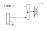
上述のように補正された補正階調データに対して、ハーフトーン処理部1152は、いわゆるドット集中型の閾値マトリックスMTXを用いて、ハーフトーン階調データを生成する。つまり、複数の画素を用いて1つのセルを形成するともに、閾値マトリックスMTXに従ってセルが有する複数の画素のうち階調レベルに対応する画素にのみ露光および現像を行ってドットを形成することで、かかるドットにより構成される網点の大きさを階調レベルに応じて変化させて階調を実現している。なお、具体的なハーフトーン処理については、後の「B.ハーフトーン処理」の項で説明する。そして、ハーフトーン処理部1152で生成されたハーフトーン階調データは、2種類のラインバッファ116A、116Bに入力される。
With respect to the corrected gradation data corrected as described above, the
これらのラインバッファ116A、116Bは画像処理ユニット15から出力される1ライン画像データを構成するハーフトーン階調データを記憶するものである点で共通するが、階調データの読出し順序が相違する。すなわち、順方向ラインバッファ116Aは1ライン画像データを構成するハーフトーン階調データを先頭から順方向に出力するものであるのに対し、逆方向ラインバッファ116Bは最後から逆方向に出力するものである。
These line buffers 116A and 116B are common in that they store halftone gradation data constituting one line image data output from the
そして、こうして出力されるハーフトーン階調データは走査モード切換部116Cに入力され、走査モード切換信号に基づき一方のラインバッファから出力されるハーフトーン階調データのみが適当なタイミングで走査モード切換部116Cからパルス変調部117に出力される。また、走査モード切換部116Cによって各色成分に対応したタイミングおよび順序で階調データがパルス変調部117に入力される。 The halftone gradation data thus output is input to the scanning mode switching unit 116C, and only the halftone gradation data output from one line buffer based on the scanning mode switching signal is scanned at an appropriate timing. 116C is output to pulse modulation section 117. In addition, the gradation data is input to the pulse modulation unit 117 at the timing and order corresponding to each color component by the scanning mode switching unit 116C.
このパルス変調部117に入力されたハーフトーニング後の階調データは、各画素に付着させるべき各色のトナードット(ドット)のサイズおよびその配列を示す多値信号であり、かかるデータを受け取ったパルス変調部117は、そのハーフトーン階調データを用いて、エンジン部EGの各色画像の露光レーザパルスをパルス幅変調するためのビデオ信号を作成し、図示を省略するビデオインターフェースを介してエンジンコントローラ10に出力する。そして、このビデオ信号に基づいて露光ユニット6のレーザー光源62YをON/OFF制御する。また、他の色成分についても同様である。
The gradation data after halftoning input to the pulse modulation unit 117 is a multi-value signal indicating the size and arrangement of toner dots (dots) of each color to be attached to each pixel. The modulation unit 117 uses the halftone gradation data to create a video signal for pulse width modulating the exposure laser pulse of each color image of the engine unit EG, and the
次に、図3に戻って説明を続ける。露光筐体61の内部には、レーザー光源62Yからの光ビームを感光体2Yの表面(図示省略)に走査露光するために、コリメータレンズ631、シリンドリカルレンズ632、偏向器65、走査レンズ66が設けられている。すなわち、レーザー光源62Yからの光ビームは、コリメータレンズ631により適当な大きさのコリメート光にビーム整形された後、副走査方向Yにのみパワーを有するシリンドリカルレンズ632に入射される。そして、シリンドリカルレンズ632を調整することでコリメート光は副走査方向Yにおいて偏向器65の偏向ミラー面651付近で結像される。このように、この実施形態では、コリメータレンズ631およびシリンドリカルレンズ632がレーザー光源62Yからの光ビームを整形するビーム整形系63として機能している。
Next, returning to FIG. In the exposure housing 61, a collimator lens 631, a cylindrical lens 632, a deflector 65, and a scanning lens 66 are provided to scan and expose the light beam from the laser light source 62Y onto the surface (not shown) of the photoreceptor 2Y. It has been. That is, the light beam from the laser light source 62Y is shaped into collimated light of an appropriate size by the collimator lens 631, and then incident on the cylindrical lens 632 having power only in the sub-scanning direction Y. Then, by adjusting the cylindrical lens 632, the collimated light is imaged in the vicinity of the deflection mirror surface 651 of the deflector 65 in the sub-scanning direction Y. Thus, in this embodiment, the collimator lens 631 and the cylindrical lens 632 function as the
この偏向器65は半導体製造技術を応用して微小機械を半導体基板上に一体形成するマイクロマシニング技術を用いて形成されるものであり、共振振動する振動ミラーで構成されている。すなわち、偏向器65では、共振振動する偏向ミラー面651により光ビームを主走査方向Xに偏向可能となっている。より具体的には、偏向ミラー面651は主走査方向Xとほぼ直交する揺動軸(ねじりバネ)周りに揺動自在に軸支されるとともに、作動部(図示省略)から与えられる外力に応じて揺動軸周りに正弦揺動する。この作動部は露光制御部102のミラー駆動部(図示省略)からのミラー駆動信号に基づき偏向ミラー面651に対して静電気的、電磁気的あるいは機械的な外力を作用させて偏向ミラー面651をミラー駆動信号の周波数で揺動させる。なお、作動部による駆動方式は静電吸着、電磁気力あるいは機械力などのいずれの方式を採用してもよく、それらの駆動方式は周知であるため、ここでは説明を省略する。
The deflector 65 is formed by using a micromachining technique in which a micromachine is integrally formed on a semiconductor substrate by applying a semiconductor manufacturing technique, and includes a vibrating mirror that resonates and oscillates. That is, in the deflector 65, the light beam can be deflected in the main scanning direction X by the deflecting mirror surface 651 that resonates and vibrates. More specifically, the deflecting mirror surface 651 is pivotally supported around a swing shaft (torsion spring) that is substantially orthogonal to the main scanning direction X, and responds to an external force applied from an operating portion (not shown). Swings sine around the swing axis. This actuating unit applies an electrostatic, electromagnetic or mechanical external force to the deflection mirror surface 651 based on a mirror drive signal from a mirror drive unit (not shown) of the
また、上記のように構成された装置では、光ビームを主走査方向に往復走査することができる、つまり光ビームを(+X)方向にも、(−X)方向にも走査可能となっている。そして、上記したように1ライン画像データを構成する階調データを記憶部(ラインバッファ116A,116B)に一時的に記憶しておき、走査モード切換部116Cが適当なタイミングおよび順序で階調データをパルス変調部117に与える。例えば(+X)方向に切り換えられた場合には、図6(a)に示すように、ラインバッファ116Aから階調データDT1,DT2,…DTnの順序で読み出され、各階調データに基づきビームスポットが第1方向(+X)に感光体2上に照射されてライン潜像LI(+X)が形成される。一方、(−X)方向に切り換えられた場合には、図6(b)に示すように、ラインバッファ116Bから階調データDTn,DT(n-1),…DT1の順序で読み出され、各階調データに基づきビームスポットが第2方向(−X)に感光体2上に照射されてライン潜像LI(-X)が形成される。
Further, in the apparatus configured as described above, the light beam can be reciprocated in the main scanning direction, that is, the light beam can be scanned in both the (+ X) direction and the (−X) direction. . As described above, the gradation data constituting one line image data is temporarily stored in the storage unit (line buffers 116A and 116B), and the scanning mode switching unit 116C performs gradation data at an appropriate timing and order. Is supplied to the pulse modulation unit 117. For example, when the direction is changed to the (+ X) direction, as shown in FIG. 6A, the beam spot is read out from the
B.ハーフトーン処理
上記「A.装置構成」の項で述べたとおり、本実施形態ではハーフトーン処理部1152において、階調補正部1151から出力される補正階調データに対してドット集中型の閾値マトリックスMTXを用いて、ハーフトーン階調データを生成する。以下、図7、8を用いて本実施形態でのハーフトーン処理について説明する。図7は、ハーフトーン処理部1152で行うハーフトーン処理を示す図である。本実施形態では、主走査方向に1画素で副走査方向に4画素の1×4セルCL14を用いて、該1×4セルCL14が有する複数の画素のうち階調レベルに対応する画素にのみ露光および現像を行ってドットを形成する。この際、どの画素にドットを形成するかは、補正階調データと次に詳述する閾値マトリックスMTXとの比較結果により決定される。つまり各画素ごとに、補正階調データと1×4閾値マトリックスMTX14の閾値とを比較して、補正階調データが対応する画素の閾値以上であれば、該画素部分にスポット潜像が形成され、未満であればスポット潜像は形成されない。例えば、補正階調データの階調レベルが2である場合は、図7の1×4セルCL14の斜線部分にスポットが形成されることとなる。
B. Halftone Processing As described in the above section “A. Device Configuration”, in this embodiment, the
図8は、1×4閾値マトリックスMTX14の動作を示す図である。図8(a)は、1×4閾値マトリックスMTX14を示す図であり、図8(b)は該1×4閾値マトリックスMTX14を用いた場合における1×4セルCL14内の網点の成長を示す図である。図8(a)に示す1×4閾値マトリックスMTX14は、ドット集中型の閾値マトリックスであり、階調レベルの増大に応じて網点の大きさを成長させている。具体的には、階調レベルが1〜4へと増大するに従って、図8(b)に示すように1×4セルCL14の有する4つの画素のうち斜線部分の画素が各階調レベルに応じて露光されることで、セルの中心部から網点が成長することとなる。 FIG. 8 is a diagram illustrating the operation of the 1 × 4 threshold matrix MTX14. FIG. 8A shows the 1 × 4 threshold matrix MTX14, and FIG. 8B shows the growth of halftone dots in the 1 × 4 cell CL14 when the 1 × 4 threshold matrix MTX14 is used. FIG. A 1 × 4 threshold value matrix MTX14 shown in FIG. 8A is a dot concentration type threshold value matrix, and the size of a halftone dot is increased as the gradation level increases. Specifically, as the gradation level increases from 1 to 4, as shown in FIG. 8B, the hatched pixels in the four pixels of the 1 × 4 cell CL14 correspond to each gradation level. By being exposed, a halftone dot grows from the center of the cell.
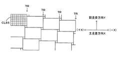
C.セルの配置方法
図9は、本実施形態での1×4セルCL14の配置方法を示す図である。ただし図9において、一点鎖線は光ビームが走査される軌跡である走査線を、太実線の長方形は1×4セルCL14を、実線楕円は感光体上での光ビームのスポットを表す。本実施形態では、1×4セルCL14を主走査方向Xに隣接して複数配置するとともに、主走査方向Xにおいてセルが相互に隣接して形成する複数の隣接位置のうち特定隣接位置TRで互いに隣接するセルが副走査方向Yにおいて奇数画素だけ相互にずれるように配置している。具体的には、特定隣接位置TRを主走査方向Xにおける隣接位置毎に設けるとともに、該特定隣接位置TRで互いに隣接するセルを、主走査方向の第1方向(+X)の上流側のセルに対して下流側のセルが副走査方向Yに1画素だけずれるように配置している。
C. Cell Arrangement Method FIG. 9 is a diagram showing an arrangement method of the 1 × 4 cell CL14 in the present embodiment. In FIG. 9, the alternate long and short dash line indicates a scanning line that is a trajectory of the light beam, the thick solid rectangle indicates the 1 × 4 cell CL14, and the solid ellipse indicates the light beam spot on the photoconductor. In the present embodiment, a plurality of 1 × 4 cells CL14 are arranged adjacent to each other in the main scanning direction X, and at a specific adjacent position TR among a plurality of adjacent positions formed by cells adjacent to each other in the main scanning direction X. Adjacent cells are arranged so as to be shifted from each other by an odd number of pixels in the sub-scanning direction Y. Specifically, a specific adjacent position TR is provided for each adjacent position in the main scanning direction X, and cells adjacent to each other at the specific adjacent position TR are cells upstream of the first direction (+ X) in the main scanning direction. The downstream cell is arranged so as to be shifted by one pixel in the sub-scanning direction Y.
D.本実施形態での発明の効果
上述のように、本実施形態では、1×4セルCL14を主走査方向Xに隣接して複数配置するとともに、特定隣接位置TRを主走査方向Xにおける隣接位置毎に設け、該特定隣接位置TRで互いに隣接する1×4セルCL14セルを、主走査方向の第1方向(+X)の上流側の1×4セルCL14に対して下流側の1×4セルCL14が副走査方向Yに1画素だけずれるように配置している。よって、図9に示すように、例えば階調レベル2の中間調を形成した場合、特定隣接位置TRを境界としてドット形成に関与する走査軌跡のピッチ関係が逆転する。つまり、主走査方向Xにおいて特定隣接位置TRに対する上流側で「広ピッチ」(または「狭ピッチ」)となる一方、下流側で「狭ピッチ」(または「広ピッチ」)となる。その結果、セルCL14に対するドット面積率が比較的大きい網点「網点大」と比較的小さい網点「網点小」とが主走査方向Xにおいて交互に現れることとなる。よって、「発明が解決しようとする課題」及び「課題を解決するための手段」で述べたような、左端(図9中の左端)から右端(図9中の右端)へと向かうに連れて濃度が低くなるという現象が抑制される。よって、主走査方向Xにおける両端間で濃度差が生じるという画像弊害を抑制して、良好な階調再現を実現できる。
D. Effects of the Invention in the Present Embodiment As described above, in the present embodiment, a plurality of 1 × 4 cells CL14 are arranged adjacent to the main scanning direction X, and a specific adjacent position TR is set for each adjacent position in the main scanning direction X. 1 × 4 cells CL14 cells adjacent to each other at the specific adjacent position TR are 1 × 4 cells on the downstream side with respect to the 1 × 4 cell CL14 on the upstream side in the first direction (+ X) in the main scanning direction. CL14 is arranged so as to be shifted by one pixel in the sub-scanning direction Y. Therefore, as shown in FIG. 9, for example, when a halftone of
<その他>
なお、本発明は上記した実施形態に限定されるものではなく、その趣旨を逸脱しない限りにおいて上述したもの以外に種々の変更を行うことが可能である。上記実施形態では、セルを配置するにあたって特定隣接位置TRをセルの主走査方向Xにおける隣接位置毎に設けたが、特定隣接位置TRの配設の態様はこれに限られるものではなく、例えば上記実施形態と同様に周期性を持たせて配設したり、非周期性で配設してもよい。また、特定隣接位置TRを周期的に配設する態様としては、上記実施形態以外に、例えば図10に示すように特定隣接位置TRを主走査方向Xにおける隣接位置2つ毎に設けてもよい。ここで図10において、一点鎖線は光ビームが走査される軌跡である走査線を、太実線の長方形は1×4セルCL14を、実線楕円は感光体上での光ビームのスポットを表す。この場合においても、図10に示すように、例えば階調レベル2の中間調を形成した場合、主走査方向Xにおいて大きい網点と小さい網点とが交互に現れることとなる。よって、主走査方向Xにおける両端間で濃度差が生じるという画像弊害を抑制して、良好な階調再現を実現できる。
<Others>
The present invention is not limited to the above-described embodiment, and various modifications other than those described above can be made without departing from the spirit of the present invention. In the above-described embodiment, the specific adjacent position TR is provided for each adjacent position in the main scanning direction X of the cell when the cells are arranged. However, the arrangement of the specific adjacent position TR is not limited to this. Similar to the embodiment, it may be provided with periodicity or may be provided with non-periodicity. Further, as a mode in which the specific adjacent positions TR are periodically arranged, the specific adjacent positions TR may be provided for every two adjacent positions in the main scanning direction X as shown in FIG. . Here, in FIG. 10, the alternate long and short dash line represents a scanning line that is a trajectory for scanning the light beam, the thick solid rectangle represents the 1 × 4 cell CL14, and the solid ellipse represents the spot of the light beam on the photoconductor. Also in this case, as shown in FIG. 10, for example, when a halftone of
また、上記実施形態では、特定隣接位置TRで互いに隣接するセルを、主走査方向の第1方向(+X)の上流側のセルに対して下流側のセルが副走査方向Yに1画素だけずれるように配置しているが、セルのずらし方としてはこれに限られるものではなく、例えば図11に示すように、主走査方向の第1方向(+X)の上流側から奇数番目の特定隣接位置TRでは主走査方向の第1方向(+X)の上流側のセルに対して下流側のセルが副走査方向に1画素だけずれるように配置する一方、主走査方向の第1方向(+X)の上流側から偶数番目の特定隣接位置TRでは主走査方向の第1方向の上流側のセルに対して下流側のセルが副走査方向と逆方向に1画素だけずれるように配置しても良い。ここで図11において、一点鎖線は光ビームが走査される軌跡である走査線を、太実線の長方形は1×4セルCL14を、実線楕円は感光体上での光ビームのスポットを表す。この場合においても、図11に示すように、例えば階調レベル2の中間調を形成した場合、主走査方向Xにおいて大きい網点と小さい網点とが交互に現れることとなる。よって、主走査方向Xにおける両端間で濃度差が生じるという画像弊害を抑制して、良好な階調再現を実現できる。すなわち、要は、特定隣接位置TRで副走査方向において互いに隣接するセルが奇数画素ずれるように配置すれば、本発明の効果を奏することができる。
Further, in the above-described embodiment, cells adjacent to each other at the specific adjacent position TR are set so that the downstream cell is only one pixel in the sub-scanning direction Y with respect to the upstream cell in the first direction (+ X) in the main scanning direction. However, the method of shifting the cells is not limited to this. For example, as shown in FIG. 11, the odd-numbered identification from the upstream side in the first direction (+ X) in the main scanning direction. In the adjacent position TR, the downstream cell is arranged so as to be shifted by one pixel in the sub scanning direction with respect to the upstream cell in the first direction (+ X) in the main scanning direction, while the first direction ( + X) at the even-numbered specific adjacent position TR from the upstream side, the downstream cell is arranged so as to be shifted by one pixel in the direction opposite to the sub-scanning direction with respect to the upstream cell in the first direction in the main scanning direction. May be. Here, in FIG. 11, the alternate long and short dash line represents a scanning line that is a trajectory of the scanning of the light beam, the thick solid line rectangle represents the 1 × 4 cell CL14, and the solid line ellipse represents the spot of the light beam on the photoconductor. Also in this case, as shown in FIG. 11, for example, when a halftone of
また、上記実施形態では、副走査方向に4画素で主走査方向Xに1画素の1×4セルを使用したが、セルの種類はこれに限られるものではなく、副走査方向に4以上の偶数個の画素を有するセルであれば本発明の効果を奏することができる。例えば、後の実施例で例示するように、4×4セル、8×6セル、8×8セル等を用いても良い。 In the above embodiment, a 1 × 4 cell having four pixels in the sub-scanning direction and one pixel in the main scanning direction X is used. However, the cell type is not limited to this, and four or more cells in the sub-scanning direction are used. If the cell has an even number of pixels, the effects of the present invention can be achieved. For example, a 4 × 4 cell, an 8 × 6 cell, an 8 × 8 cell, or the like may be used as illustrated in a later embodiment.
また、上記実施形態は、いわゆるタンデム方式のカラープリンタについて本発明を適用したものであるが、本発明の適用範囲はこれに限られるものではなく、例えばいわゆる4サイクル方式のプリンタや単色印字のみを行うモノクロプリンタについても適用可能である。 In the above-described embodiment, the present invention is applied to a so-called tandem color printer, but the scope of the present invention is not limited to this. For example, only a so-called four-cycle printer or single color printing is used. The present invention can also be applied to a monochrome printer.
また、上記実施形態では、中間転写ベルトなどの中間転写媒体に一時的にカラー画像を形成した後に該カラー画像をシートSに転写する画像形成装置に対して本発明を適用しているが、各トナー像を直接シート上で重ね合わせてカラー画像を形成する装置に対しても適用可能である。 In the above embodiment, the present invention is applied to an image forming apparatus that temporarily forms a color image on an intermediate transfer medium such as an intermediate transfer belt and then transfers the color image to the sheet S. The present invention is also applicable to an apparatus that forms a color image by directly superimposing toner images on a sheet.
また、上記実施形態では、振動する偏向ミラー面651をマイクロマシニング技術を用いて形成しているが、偏向ミラー面の製造方法はこれに限定されるものではなく、振動する偏向ミラー面を用いて光ビームを偏向して潜像担持体上に光ビームを走査させる、いわゆる画像形成装置全般に本発明を適用することができる。 In the above embodiment, the vibrating deflection mirror surface 651 is formed by using a micromachining technique. However, the method of manufacturing the deflection mirror surface is not limited to this, and the vibrating deflection mirror surface is used. The present invention can be applied to all so-called image forming apparatuses in which a light beam is deflected to scan the latent image carrier.
次に本発明の実施例を示すが、本発明はもとより下記の実施例によって制限を受けるものではなく、前後記の趣旨に適合しうる範囲で適当に変更を加えて実施することも勿論可能であり、それらはいずれも本発明の技術的範囲に含まれる。 Next, examples of the present invention will be shown. However, the present invention is not limited by the following examples as a matter of course, and it is of course possible to implement the present invention with appropriate modifications within a range that can meet the gist of the preceding and following descriptions. They are all included in the technical scope of the present invention.
以下に、本発明の効果を示すために、本発明の実施例である実施例1〜14により中間調画像を形成した場合と、従来の階調再現を用いた比較例1〜4により中間調画像を形成した場合とを比較した際の結果について説明する。 In the following, in order to show the effect of the present invention, a halftone image is formed in the case where a halftone image is formed according to Examples 1 to 14 which are examples of the present invention, and in Comparative Examples 1 to 4 using conventional gradation reproduction. The result when comparing with the case of forming an image will be described.
実施例1〜14および比較例1〜4のいずれも、マイクロソフト社のWordを用いて25%濃度のシアン色のハーフトーン画像を用紙の両端に作成し、これら両端間の濃度差を測定した。なお、濃度測定は、グレタグマクベス社のスペクトロリノを用いるとともに、測定誤差を考慮して5点平均を測定値として採用した。 In each of Examples 1 to 14 and Comparative Examples 1 to 4, 25% density cyan halftone images were created on both ends of the paper using Microsoft Word, and the density difference between these ends was measured. In addition, for the concentration measurement, a spectrolino manufactured by Gretag Macbeth was used, and an average of 5 points was adopted as a measured value in consideration of measurement error.
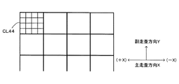
実施例1〜6及び比較例1,2は4×4セルCL44を、実施例7〜10及び比較例3は8×6セルCL86を、実施例11〜14及び比較例4は8×8セルCL88を用いることとし、それぞれセルの配置方法を変更している。また、各種セルに対応して、それぞれ4×4閾値マトリックスMTX44、8×6閾値マトリックスMTX86、8×8閾値マトリックスMTX88を用いる。図12は、実施例及び比較例で用いた閾値マトリックスを示したものであり、図12(a)は4×4閾値マトリックスMTX44を、図12(b)は8×6閾値マトリックスMTX86を、図12(c)は8×8閾値マトリックスMTX88を示す。また、これらの閾値マトリックスMTX44,86,88はいずれもドット集中型の閾値マトリックスであり、図12の(a)〜(c)に示すようにマトリックスの中心部から外へと向かうにつれて閾値が大きくなるように構成されている。なお、各閾値マトリックスの閾値は、4×4の場合は16が濃度100%に、8×6の場合は48が濃度100%に、8×8の場合は64が濃度100%に対応する。従って、濃度25%の中間調を形成するにあたっては、4×4セルCL44の場合は閾値が4以下に対応する画素にドットが形成され、8×6セルCL86の場合は閾値が12以下に対応する画素にドットが形成され、8×8セルCL88の場合は閾値が16以下に対応する画素にドットが形成されることとなる。また、解像度は、4×4セルCL44では600×600dpi(dot per inch)とし、8×6セルCL86および8×8セルCL88では1200×1200dpiとした。 Examples 1 to 6 and Comparative Examples 1 and 2 are 4 × 4 cells CL44, Examples 7 to 10 and Comparative Example 3 are 8 × 6 cells CL86, and Examples 11 to 14 and Comparative Example 4 are 8 × 8 cells. CL88 is used, and the cell arrangement method is changed. Also, a 4 × 4 threshold matrix MTX44, an 8 × 6 threshold matrix MTX86, and an 8 × 8 threshold matrix MTX88 are used corresponding to various cells, respectively. FIG. 12 shows threshold matrixes used in the examples and comparative examples. FIG. 12A shows a 4 × 4 threshold matrix MTX44, FIG. 12B shows an 8 × 6 threshold matrix MTX86, and FIG. 12 (c) shows an 8 × 8 threshold matrix MTX88. These threshold value matrices MTX44, 86, and 88 are all dot-concentrated type threshold value matrices, and the threshold values increase as they go outward from the center of the matrix as shown in FIGS. 12 (a) to 12 (c). It is comprised so that it may become. Note that the threshold value of each threshold value matrix corresponds to a density of 100% for 4 × 4, 48 to 100% for 8 × 6, and 64 to 100% for 8 × 8. Therefore, when forming a halftone with a density of 25%, a dot is formed in a pixel corresponding to a threshold value of 4 or less in the case of 4 × 4 cells CL44, and a threshold value of 12 or less in the case of 8 × 6 cells CL86. In the case of the 8 × 8 cell CL88, a dot is formed in a pixel corresponding to a threshold value of 16 or less. The resolution was 600 × 600 dpi (dot per inch) in the 4 × 4 cell CL44, and 1200 × 1200 dpi in the 8 × 6 cell CL86 and the 8 × 8 cell CL88.
図13は実施例1でのセルの配置方法を示す図である。実施例1では4×4セルCL44を用いるとともに、特定隣接位置TRを主走査方向Xにおける隣接位置毎に設け、該特定隣接位置TRで互いに隣接するセルを、主走査方向の第1方向(+X)の上流側のセルに対して下流側のセルが副走査方向Yに1画素だけずれるように配置している。 FIG. 13 is a diagram illustrating a cell arrangement method according to the first embodiment. In the first embodiment, a 4 × 4 cell CL44 is used, and a specific adjacent position TR is provided for each adjacent position in the main scanning direction X, and cells adjacent to each other at the specific adjacent position TR are arranged in the first direction (+ The downstream cell is arranged so as to be shifted by one pixel in the sub-scanning direction Y with respect to the upstream cell of X).
図14は実施例2でのセルの配置方法を示す図である。実施例2では4×4セルCL44を用いるとともに、特定隣接位置TRを主走査方向Xにおける隣接位置毎に設け、該特定隣接位置TRで互いに隣接するセルを、主走査方向の第1方向(+X)の上流側のセルに対して下流側のセルが副走査方向Yに1画素だけずれるように配置している。さらに、副走査方向Yの下流側のセルに対して上流側のセルが主走査方向の第1方向(+X)に1画素だけずれるように配置している。 FIG. 14 is a diagram illustrating a cell arrangement method according to the second embodiment. In the second embodiment, a 4 × 4 cell CL44 is used, and a specific adjacent position TR is provided for each adjacent position in the main scanning direction X, and cells adjacent to each other at the specific adjacent position TR are arranged in the first direction (+ The downstream cell is arranged so as to be shifted by one pixel in the sub-scanning direction Y with respect to the upstream cell of X). Further, the upstream cell is arranged so as to be shifted by one pixel in the first direction (+ X) in the main scanning direction with respect to the downstream cell in the sub-scanning direction Y.
図15は実施例3でのセルの配置方法を示す図である。実施例3では4×4セルCL44を用いるとともに、特定隣接位置TRを主走査方向Xにおける隣接位置毎に設け、該特定隣接位置TRで互いに隣接するセルを、主走査方向の第1方向(+X)の上流側のセルに対して下流側のセルが副走査方向Yに1画素だけずれるように配置している。さらに、副走査方向Yの下流側のセルに対して上流側のセルが主走査方向の第1方向(+X)に2画素だけずれるように配置している。 FIG. 15 is a diagram illustrating a cell arrangement method according to the third embodiment. In the third embodiment, a 4 × 4 cell CL44 is used, a specific adjacent position TR is provided for each adjacent position in the main scanning direction X, and cells adjacent to each other at the specific adjacent position TR are arranged in the first direction (+ The downstream cell is arranged so as to be shifted by one pixel in the sub-scanning direction Y with respect to the upstream cell of X). Further, the upstream cell is arranged so as to be shifted by 2 pixels in the first direction (+ X) in the main scanning direction with respect to the downstream cell in the sub-scanning direction Y.
図16は実施例4でのセルの配置方法を示す図である。実施例4では4×4セルCL44を用いるとともに、特定隣接位置TRを主走査方向Xにおける隣接位置毎に設け、主走査方向Xの第1方向の上流側から奇数番目の特定隣接位置TRでは主走査方向の第1方向の上流側のセルに対して下流側のセルが副走査方向に1画素だけずれるように配置する一方、主走査方向の第1方向の上流側から偶数番目の特定隣接位置TRでは主走査方向の第1方向の上流側のセルに対して下流側のセルが副走査方向と逆方向に1画素だけずれるように配置している。 FIG. 16 is a diagram illustrating a cell arrangement method according to the fourth embodiment. In the fourth embodiment, a 4 × 4 cell CL44 is used, and a specific adjacent position TR is provided for each adjacent position in the main scanning direction X. In the odd-numbered specific adjacent position TR from the upstream side in the first direction in the main scanning direction X, While the downstream cells are arranged so as to be shifted by one pixel in the sub-scanning direction with respect to the upstream cells in the first direction in the scanning direction, the even-numbered specific adjacent positions from the upstream side in the first direction in the main scanning direction In TR, the downstream cell is arranged so as to be shifted by one pixel in the direction opposite to the sub-scanning direction with respect to the upstream cell in the first direction in the main scanning direction.
図17は実施例5でのセルの配置方法を示す図である。実施例5では4×4セルCL44を用いるとともに、特定隣接位置TRを主走査方向Xにおける隣接位置2つ毎に設け、該特定隣接位置TRで互いに隣接するセルを、主走査方向の第1方向(+X)の上流側のセルに対して下流側のセルが副走査方向Yに1画素だけずれるように配置している。 FIG. 17 is a diagram illustrating a cell arrangement method according to the fifth embodiment. In the fifth embodiment, a 4 × 4 cell CL44 is used, and a specific adjacent position TR is provided for every two adjacent positions in the main scanning direction X, and cells adjacent to each other at the specific adjacent position TR are arranged in the first direction in the main scanning direction. The cells on the downstream side are arranged so as to be shifted by one pixel in the sub-scanning direction Y with respect to the cells on the upstream side of (+ X).
図18は実施例6でのセルの配置方法を示す図である。実施例6では4×4セルCL44を用いるとともに、特定隣接位置TRを主走査方向における隣接位置3つ毎に設け、該特定隣接位置TRで互いに隣接するセルを、主走査方向の第1方向(+X)の上流側のセルに対して下流側のセルが副走査方向Yに1画素だけずれるように配置している。 FIG. 18 is a diagram illustrating a cell arrangement method according to the sixth embodiment. In the sixth embodiment, a 4 × 4 cell CL44 is used, and a specific adjacent position TR is provided for every three adjacent positions in the main scanning direction, and cells adjacent to each other at the specific adjacent position TR are arranged in the first direction ( + X) is arranged so that the downstream cell is shifted by one pixel in the sub-scanning direction Y with respect to the upstream cell.
図19は実施例7でのセルの配置方法を示す図である。実施例7では8×6セルCL86を用いるとともに、特定隣接位置TRを主走査方向Xにおける隣接位置毎に設け、該特定隣接位置TRで互いに隣接するセルを、主走査方向の第1方向(+X)の上流側のセルに対して下流側のセルが副走査方向Yに1画素だけずれるように配置している。 FIG. 19 is a diagram illustrating a cell arrangement method according to the seventh embodiment. In the seventh embodiment, 8 × 6 cells CL86 are used, and a specific adjacent position TR is provided for each adjacent position in the main scanning direction X, and cells adjacent to each other at the specific adjacent position TR are arranged in the first direction (+ The downstream cell is arranged so as to be shifted by one pixel in the sub-scanning direction Y with respect to the upstream cell of X).
図20は実施例8でのセルの配置方法を示す図である。実施例8では8×6セルCL86を用いるとともに、特定隣接位置TRを主走査方向Xにおける隣接位置毎に設け、主走査方向の第1方向の上流側から奇数番目の特定隣接位置TRでは主走査方向の第1方向の上流側のセルに対して下流側のセルが副走査方向に3画素だけずれるように配置する一方、主走査方向の第1方向の上流側から偶数番目の特定隣接位置TRでは主走査方向の第1方向の上流側のセルに対して下流側のセルが副走査方向と逆方向に3画素だけずれるように配置している。 FIG. 20 is a diagram illustrating a cell arrangement method according to the eighth embodiment. In the eighth embodiment, 8 × 6 cells CL86 are used, and a specific adjacent position TR is provided for each adjacent position in the main scanning direction X. In the odd-numbered specific adjacent position TR from the upstream side in the first direction in the main scanning direction, main scanning is performed. While the downstream cells are arranged so as to be shifted by 3 pixels in the sub-scanning direction with respect to the upstream cells in the first direction, the even-numbered specific adjacent position TR from the upstream side in the first direction in the main scanning direction In this case, the downstream cells are arranged so as to be shifted by 3 pixels in the direction opposite to the sub scanning direction with respect to the upstream cells in the first direction in the main scanning direction.
図21は実施例9でのセルの配置方法を示す図である。実施例9では8×6セルCL86を用いるとともに、特定隣接位置TRを主走査方向Xにおける隣接位置2つ毎に設け、該特定隣接位置TRで互いに隣接するセルを、主走査方向の第1方向(+X)の上流側のセルに対して下流側のセルが副走査方向Yに1画素だけずれるように配置している。 FIG. 21 is a diagram illustrating a cell arrangement method according to the ninth embodiment. In the ninth embodiment, 8 × 6 cells CL86 are used, and a specific adjacent position TR is provided for every two adjacent positions in the main scanning direction X, and cells adjacent to each other at the specific adjacent position TR are arranged in the first direction in the main scanning direction. The cells on the downstream side are arranged so as to be shifted by one pixel in the sub-scanning direction Y with respect to the cells on the upstream side of (+ X).
図22は実施例10でのセルの配置方法を示す図である。実施例10では8×6セルCL86を用いるとともに、特定隣接位置TRを主走査方向Xにおける隣接位置毎に設け、該特定隣接位置TRで互いに隣接するセルを、主走査方向の第1方向(+X)の上流側のセルに対して下流側のセルが副走査方向Yに1画素だけずれるように配置している。さらに、副走査方向Yの下流側のセルに対して上流側のセルが主走査方向の第1方向(+X)に1画素だけずれるように配置している。 FIG. 22 is a diagram illustrating a cell arrangement method according to the tenth embodiment. In the tenth embodiment, 8 × 6 cells CL86 are used, and a specific adjacent position TR is provided for each adjacent position in the main scanning direction X, and cells adjacent to each other at the specific adjacent position TR are arranged in the first direction (+ The downstream cell is arranged so as to be shifted by one pixel in the sub-scanning direction Y with respect to the upstream cell of X). Further, the upstream cell is arranged so as to be shifted by one pixel in the first direction (+ X) in the main scanning direction with respect to the downstream cell in the sub-scanning direction Y.
図23は実施例11でのセルの配置方法を示す図である。実施例11では、8×8セルCL88を用いるとともに、特定隣接位置TRを主走査方向Xにおける隣接位置毎に設け、該特定隣接位置TRで互いに隣接するセルを、主走査方向の第1方向(+X)の上流側のセルに対して下流側のセルが副走査方向Yに1画素だけずれるように配置している。 FIG. 23 is a diagram illustrating a cell arrangement method according to the eleventh embodiment. In the eleventh embodiment, the 8 × 8 cell CL88 is used and a specific adjacent position TR is provided for each adjacent position in the main scanning direction X, and cells adjacent to each other at the specific adjacent position TR are arranged in the first direction in the main scanning direction ( + X) is arranged so that the downstream cell is shifted by one pixel in the sub-scanning direction Y with respect to the upstream cell.
図24は実施例12でのセルの配置方法を示す図である。実施例12では、8×8セルCL88を用いるとともに、特定隣接位置TRを主走査方向における隣接位置毎に設け、該特定隣接位置TRで互いに隣接するセルを、主走査方向の第1方向(+X)の上流側のセルに対して下流側のセルが副走査方向Yに3画素だけずれるように配置している。 FIG. 24 is a diagram illustrating a cell arrangement method according to the twelfth embodiment. In the twelfth embodiment, the 8 × 8 cell CL88 is used and a specific adjacent position TR is provided for each adjacent position in the main scanning direction, and cells adjacent to each other at the specific adjacent position TR are arranged in the first direction (+ The downstream cells are arranged so as to be shifted by 3 pixels in the sub-scanning direction Y with respect to the upstream cells of X).
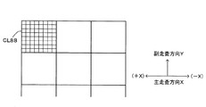
図25は実施例13でのセルの配置方法を示す図である。実施例13では、8×8セルCL88を用いるとともに、特定隣接位置TRを主走査方向Xにおける隣接位置2つ毎に設け、該特定隣接位置TRで互いに隣接するセルを、主走査方向の第1方向(+X)の上流側のセルに対して下流側のセルが副走査方向Yに1画素だけずれるように配置している。 FIG. 25 is a diagram illustrating a cell arrangement method according to the thirteenth embodiment. In the thirteenth embodiment, an 8 × 8 cell CL88 is used, and a specific adjacent position TR is provided for every two adjacent positions in the main scanning direction X, and cells adjacent to each other at the specific adjacent position TR are defined as the first in the main scanning direction. The cells on the downstream side are arranged so as to be shifted by one pixel in the sub-scanning direction Y with respect to the cells on the upstream side in the direction (+ X).
図26は実施例14でのセルの配置方法を示す図である。実施例14では、8×8セルCL88を用いるとともに、特定隣接位置TRを主走査方向Xにおける隣接位置毎に設け、該特定隣接位置TRで互いに隣接するセルを、主走査方向の第1方向(+X)の上流側のセルに対して下流側のセルが副走査方向Yに1画素だけずれるように配置している。さらに、副走査方向Yの下流側のセルに対して上流側のセルが主走査方向の第1方向(+X)に1画素だけずれるように配置している。 FIG. 26 is a diagram illustrating a cell arrangement method according to the fourteenth embodiment. In the fourteenth embodiment, an 8 × 8 cell CL88 is used, and a specific adjacent position TR is provided for each adjacent position in the main scanning direction X, and cells adjacent to each other at the specific adjacent position TR are arranged in the first direction ( + X) is arranged so that the downstream cell is shifted by one pixel in the sub-scanning direction Y with respect to the upstream cell. Further, the upstream cell is arranged so as to be shifted by one pixel in the first direction (+ X) in the main scanning direction with respect to the downstream cell in the sub-scanning direction Y.
図27は比較例1でのセルの配置方法を示す図である。比較例1では4×4セルCL44を主走査方向Xに隣接して配置するとともに、主走査方向Xにおけるいずれの隣接位置においても、互いに隣接するセル間にずれを設けていない。 FIG. 27 is a diagram showing a cell arrangement method in the first comparative example. In the first comparative example, the 4 × 4 cells CL44 are arranged adjacent to each other in the main scanning direction X, and no shift is provided between adjacent cells at any adjacent position in the main scanning direction X.
図28は比較例2でのセルの配置方法を示す図である。比較例2では4×4セルCL44を主走査方向Xに隣接して配置するとともに、主走査方向Xにおいてセルが相互に隣接して形成する隣接位置のうち、主走査方向の第1方向の上流側から奇数番目の隣接位置では主走査方向の第1方向の上流側のセルに対して下流側のセルが副走査方向に2画素だけずれるように配置する一方、主走査方向の第1方向の上流側から偶数番目の隣接位置では主走査方向の第1方向の上流側のセルに対して下流側のセルが副走査方向と逆方向に2画素だけずれるように配置している。 FIG. 28 is a diagram illustrating a cell arrangement method in the second comparative example. In Comparative Example 2, 4 × 4 cells CL44 are arranged adjacent to each other in the main scanning direction X, and among the adjacent positions formed by the cells adjacent to each other in the main scanning direction X, upstream in the first direction in the main scanning direction. The odd-numbered adjacent positions from the side are arranged so that the downstream cell is shifted by 2 pixels in the sub-scanning direction with respect to the upstream cell in the first direction in the main scanning direction, while in the first direction in the main scanning direction At even-numbered adjacent positions from the upstream side, the downstream cells are arranged so as to be shifted by two pixels in the direction opposite to the sub-scanning direction with respect to the upstream cells in the first direction in the main scanning direction.
図29は比較例3でのセルの配置方法を示す図である。比較例3では8×6セルCL86を主走査方向Xに隣接して配置するとともに、主走査方向Xにおけるいずれの隣接位置においても、互いに隣接するセル間にずれを設けていない。 FIG. 29 is a diagram showing a cell arrangement method in the third comparative example. In Comparative Example 3, 8 × 6 cells CL86 are arranged adjacent to each other in the main scanning direction X, and no shift is provided between adjacent cells at any adjacent position in the main scanning direction X.
図30は比較例4でのセルの配置方法を示す図である。比較例4では8×8セルCL88を主走査方向Xに隣接して配置するとともに、主走査方向Xにおけるいずれの隣接位置においても、互いに隣接するセル間にずれを設けていない。 FIG. 30 is a diagram showing a cell arrangement method in Comparative Example 4. In Comparative Example 4, 8 × 8 cells CL88 are arranged adjacent to each other in the main scanning direction X, and no shift is provided between adjacent cells at any adjacent position in the main scanning direction X.
下の表1は、上記実施例および比較例により用紙の両端に中間調を形成した場合の濃度差の測定結果を示した表である。まず、4×4セルCL44を用いた実施例1〜6と比較例1、2との結果を比較すると、本発明の実施例1〜6では左右での濃度差が絶対値にして0.01以下であるのに対して、従来の階調再現を用いた比較例1、2では絶対値にして0.06以上となっており、本発明の実施例1〜6の方が比較例1、2と比較して左右の濃度差が抑えられているのが判る。すなわち、本発明の実施例1〜6によれば、主走査方向における両端間で濃度差が生じるという画像弊害を抑制して、良好な階調再現を実現できることが判った。 Table 1 below is a table showing the measurement results of the density difference when halftones are formed on both ends of the paper according to the above examples and comparative examples. First, comparing the results of Examples 1 to 6 and Comparative Examples 1 and 2 using the 4 × 4 cell CL44, in Examples 1 to 6 of the present invention, the concentration difference between the left and right is 0.01. In contrast to the following, in Comparative Examples 1 and 2 using conventional gradation reproduction, the absolute value is 0.06 or more, and Examples 1 to 6 of the present invention are Comparative Examples 1 and 6. It can be seen that the density difference between the left and right is suppressed compared to 2. That is, according to Examples 1 to 6 of the present invention, it was found that good gradation reproduction can be realized by suppressing the image adverse effect of density difference between both ends in the main scanning direction.
次に、8×6セルCL86を用いた実施例7〜10と比較例3との結果を比較すると、本発明の実施例7〜10では左右での濃度差が絶対値にして0.01以下であるのに対して、従来の階調再現を用いた比較例3では絶対値にして0.05となっており、本発明の実施例7〜10の方が比較例3と比較して左右の濃度差が抑えられているのが判る。すなわち、本発明の実施例7〜10によれば、主走査方向における両端間で濃度差が生じるという画像弊害を抑制して、良好な階調再現を実現できることが判った。 Next, comparing the results of Examples 7 to 10 and Comparative Example 3 using the 8 × 6 cell CL86, in Examples 7 to 10 of the present invention, the concentration difference between the left and right is 0.01 or less in absolute value. On the other hand, in the comparative example 3 using the conventional gradation reproduction, the absolute value is 0.05, and the examples 7 to 10 of the present invention are left and right as compared with the comparative example 3. It can be seen that the difference in the concentration of is suppressed. That is, according to Examples 7 to 10 of the present invention, it has been found that good gradation reproduction can be realized by suppressing the image adverse effect that a density difference occurs between both ends in the main scanning direction.
次に、8×8セルCL88を用いた実施例11〜14と比較例4との結果を比較すると、本発明の実施例11〜14では左右での濃度差が絶対値にして0.01以下であるのに対して、従来の階調再現を用いた比較例4では絶対値にして0.06となっており、本発明の実施例11〜14の方が比較例4と比較して左右の濃度差が抑えられているのが判る。すなわち、本発明の実施例11〜14によれば、主走査方向における両端間で濃度差が生じるという画像弊害を抑制して、良好な階調再現を実現できることが判った。 Next, comparing the results of Examples 11 to 14 and Comparative Example 4 using the 8 × 8 cell CL88, in Examples 11 to 14 of the present invention, the concentration difference between the left and right is 0.01 or less in absolute value. On the other hand, in the comparative example 4 using the conventional gradation reproduction, the absolute value is 0.06, and the examples 11 to 14 of the present invention are more right and left than the comparative example 4. It can be seen that the difference in the concentration of is suppressed. That is, according to Examples 11 to 14 of the present invention, it has been found that good gradation reproduction can be realized while suppressing an image adverse effect that a density difference occurs between both ends in the main scanning direction.

2,2Y,2M,2C,2K…感光体(潜像担持体)、 6,6Y,6M,6C,6K…露光ユニット、 60…水平同期センサ、 62,62Y,62M,62C,62K…レーザー光源、 71…中間転写ベルト、 651…偏向ミラー面、 DT1,DT2,DT(n-1),DTn…階調データ、 Ly,Lm,Lc,Lk…走査光ビーム、 LI(+X),LI(-X)…ライン潜像、 MT…駆動モータ、 X…主走査方向、 Y…副走査方向、TR…特定隣接位置、 MTX,MTX14,MTX44,MTX86,MTX88…閾値マトリックス、 CL,CL14,CL44,CL86,CL88…セル 2, 2Y, 2M, 2C, 2K ... photosensitive member (latent image carrier), 6, 6Y, 6M, 6C, 6K ... exposure unit, 60 ... horizontal synchronization sensor, 62, 62Y, 62M, 62C, 62K ... laser light source 71: Intermediate transfer belt 651: Deflection mirror surface DT1, DT2, DT (n-1), DTn: Gradation data, Ly, Lm, Lc, Lk: Scanning light beam, LI (+ X), LI ( -X) ... Line latent image, MT ... Drive motor, X ... Main scanning direction, Y ... Sub-scanning direction, TR ... Specific adjacent position, MTX, MTX14, MTX44, MTX86, MTX88 ... Threshold matrix, CL, CL14, CL44, CL86, CL88 ... cell
Claims (6)
網点の形成に寄与する複数の画素からなるセルに対して、前記画素の現像の際に閾値マトリックスを用いて前記網点を形成することにより画像を形成する画像形成方法であって、
前記偏向ミラー面によって前記光ビームを前記第2の方向に往復走査して前記潜像を形成し、
前記第1の方向に対し4以上で且つ偶数個の画素を有するセルが、前記第2の方向に隣接して配置されるとともに、前記第2の方向において前記偶数個の画素を有するセルが隣接して形成する隣接位置のうち、特定隣接位置において前記偶数個の画素を有するセルが前記特定隣接位置を介して隣接するセルに対して前記第1の方向の奇数画素の長さ分前記第1の方向にずれるように配置することを特徴とする画像形成方法。 The latent image carrier whose surface is driven in the first direction and the oscillating deflection mirror surface are configured so that the light from the light source can be scanned in the second direction substantially orthogonal to the first direction, and the light is Using an image forming apparatus comprising a latent image forming unit that irradiates a latent image carrier to form a latent image and a developing unit that develops the latent image,
An image forming method for forming an image by forming a halftone dot using a threshold matrix at the time of developing the pixel for a cell composed of a plurality of pixels contributing to the formation of a halftone dot,
Reciprocatingly scanning the light beam in the second direction with the deflecting mirror surface to form the latent image;
Cells having an even number of pixels that are 4 or more with respect to the first direction are arranged adjacent to the second direction, and the cells having the even number of pixels are adjacent to each other in the second direction. Among the adjacent positions to be formed, a cell having the even number of pixels at the specific adjacent position has a length equal to the number of odd pixels in the first direction with respect to a cell adjacent through the specific adjacent position. An image forming method, wherein the image forming method is arranged so as to deviate in the direction of.
網点の形成に寄与する複数の画素からなるセルに対して、前記画素の現像の際に閾値マトリックスを用いて前記網点を形成することにより画像を形成する手段とを備え、
前記偏向ミラー面によって前記光ビームを前記第2の方向に往復走査して前記潜像を形成する手段と、
前記第1の方向に対し4以上で且つ偶数個の画素を有するセルが、前記第2の方向に隣接して配置されるとともに、前記第2の方向において前記偶数個の画素を有するセルが隣接して形成する隣接位置のうち、特定隣接位置において前記偶数個の画素を有するセルが前記特定隣接位置を介して隣接するセルに対して前記第1の方向の奇数画素の長さ分前記第1の方向にずれるように配置する手段とを備える画像形成装置。 The latent image carrier whose surface is driven in the first direction and the oscillating deflection mirror surface are configured so that the light from the light source can be scanned in the second direction substantially orthogonal to the first direction, and the light is A latent image forming unit that irradiates the latent image carrier to form a latent image; and a developing unit that develops the latent image;
Means for forming an image by forming the halftone dots using a threshold matrix when developing the pixels for a cell consisting of a plurality of pixels contributing to the formation of halftone dots;
Means for reciprocally scanning the light beam in the second direction with the deflecting mirror surface to form the latent image;
Cells having an even number of pixels that are 4 or more with respect to the first direction are arranged adjacent to the second direction, and the cells having the even number of pixels are adjacent to each other in the second direction. Among the adjacent positions to be formed, a cell having the even number of pixels at the specific adjacent position has a length equal to the number of odd pixels in the first direction with respect to a cell adjacent through the specific adjacent position. And an image forming apparatus provided with a unit arranged so as to be displaced in the direction of.
Priority Applications (3)
| Application Number | Priority Date | Filing Date | Title |
|---|---|---|---|
| JP2005249795A JP4779509B2 (en) | 2005-08-30 | 2005-08-30 | Image forming method and image forming apparatus |
| US11/463,155 US7405743B2 (en) | 2005-08-30 | 2006-08-08 | Image forming method and apparatus |
| US12/138,266 US7815276B2 (en) | 2005-08-30 | 2008-06-12 | Image forming method and apparatus |
Applications Claiming Priority (1)
| Application Number | Priority Date | Filing Date | Title |
|---|---|---|---|
| JP2005249795A JP4779509B2 (en) | 2005-08-30 | 2005-08-30 | Image forming method and image forming apparatus |
Publications (3)
| Publication Number | Publication Date |
|---|---|
| JP2007062096A JP2007062096A (en) | 2007-03-15 |
| JP2007062096A5 JP2007062096A5 (en) | 2008-10-23 |
| JP4779509B2 true JP4779509B2 (en) | 2011-09-28 |
Family
ID=37924876
Family Applications (1)
| Application Number | Title | Priority Date | Filing Date |
|---|---|---|---|
| JP2005249795A Expired - Fee Related JP4779509B2 (en) | 2005-08-30 | 2005-08-30 | Image forming method and image forming apparatus |
Country Status (1)
| Country | Link |
|---|---|
| JP (1) | JP4779509B2 (en) |
Families Citing this family (4)
| Publication number | Priority date | Publication date | Assignee | Title |
|---|---|---|---|---|
| JP4519875B2 (en) * | 2006-04-11 | 2010-08-04 | キヤノン株式会社 | Data processing apparatus and data processing method |
| US7924459B2 (en) | 2006-04-11 | 2011-04-12 | Canon Kabushiki Kaisha | Data processing apparatus and method of expanding dot arrangement patterns |
| JP4821663B2 (en) | 2007-03-12 | 2011-11-24 | 日本電気株式会社 | Character noise elimination device, character noise elimination method, character noise elimination program |
| JP5194282B2 (en) * | 2007-07-13 | 2013-05-08 | マーベル ワールド トレード リミテッド | Method and apparatus for laser oscillating mirror support for color printer |
Family Cites Families (9)
| Publication number | Priority date | Publication date | Assignee | Title |
|---|---|---|---|---|
| JPS58207768A (en) * | 1982-05-28 | 1983-12-03 | Fujitsu Ltd | Controlling system of scanning |
| JPH084297B2 (en) * | 1983-06-09 | 1996-01-17 | 富士写真フイルム株式会社 | Radiation image information reading error correction method |
| JP3036186B2 (en) * | 1991-12-04 | 2000-04-24 | 富士写真フイルム株式会社 | Color image recording method |
| JP3767209B2 (en) * | 1998-09-25 | 2006-04-19 | セイコーエプソン株式会社 | Image processing apparatus and method, and printing apparatus |
| JP2001169108A (en) * | 1999-12-06 | 2001-06-22 | Brother Ind Ltd | Image-forming device |
| JP2002296534A (en) * | 2001-03-29 | 2002-10-09 | Fuji Photo Film Co Ltd | Image recorder |
| JP4398676B2 (en) * | 2003-06-30 | 2010-01-13 | 株式会社リコー | Deflection mirror, optical scanning device, and image forming apparatus |
| JP2005161817A (en) * | 2003-12-05 | 2005-06-23 | Canon Inc | Method and device for image processing |
| JP2005174438A (en) * | 2003-12-10 | 2005-06-30 | Fujitsu Ten Ltd | Insertion/ejection device of recording medium |
-
2005
- 2005-08-30 JP JP2005249795A patent/JP4779509B2/en not_active Expired - Fee Related
Also Published As
| Publication number | Publication date |
|---|---|
| JP2007062096A (en) | 2007-03-15 |
Similar Documents
| Publication | Publication Date | Title |
|---|---|---|
| JP2006305969A (en) | Image forming device, and image forming method | |
| US7815276B2 (en) | Image forming method and apparatus | |
| JP4779509B2 (en) | Image forming method and image forming apparatus | |
| JP2007062099A (en) | Image formation method and image forming apparatus | |
| JP5404340B2 (en) | Image forming apparatus, image forming method, and program | |
| JP4779510B2 (en) | Image forming method and image forming apparatus | |
| JP2007199556A (en) | Optical scanner, method of controlling the same and image forming apparatus using the same | |
| JP4848747B2 (en) | Image forming apparatus | |
| JP5277529B2 (en) | Optical scanning device, method of controlling the device, image forming apparatus using the device, and image forming method | |
| JP4461943B2 (en) | Image forming apparatus and image forming method | |
| JP4572333B2 (en) | Image forming apparatus and image forming method | |
| JP4858637B2 (en) | Image forming apparatus | |
| JP4956971B2 (en) | Image forming apparatus | |
| JP2007140397A (en) | Image forming method and image forming apparatus | |
| JP4930559B2 (en) | Data control apparatus, data control method, and image forming apparatus | |
| JP4835121B2 (en) | Image forming apparatus | |
| JP4779447B2 (en) | Image forming apparatus and image forming method | |
| JP2006035553A5 (en) | ||
| JP2006035554A (en) | Image forming apparatus, image formation method and data controller | |
| JP2007062098A (en) | Image formation method and image forming apparatus | |
| JP4923608B2 (en) | Optical scanning device, method for controlling the device, and image forming apparatus using the device | |
| JP4581859B2 (en) | Image forming apparatus and control method thereof | |
| JP2007140398A (en) | Image forming apparatus | |
| JP2006035550A (en) | Image forming apparatus and image formation method | |
| JP2006035551A (en) | Image forming apparatus, image formation method and data controller |
Legal Events
| Date | Code | Title | Description |
|---|---|---|---|
| A521 | Written amendment |
Free format text: JAPANESE INTERMEDIATE CODE: A523 Effective date: 20080829 |
|
| A621 | Written request for application examination |
Free format text: JAPANESE INTERMEDIATE CODE: A621 Effective date: 20080829 |
|
| A977 | Report on retrieval |
Free format text: JAPANESE INTERMEDIATE CODE: A971007 Effective date: 20110216 |
|
| A131 | Notification of reasons for refusal |
Free format text: JAPANESE INTERMEDIATE CODE: A131 Effective date: 20110322 |
|
| A521 | Written amendment |
Free format text: JAPANESE INTERMEDIATE CODE: A523 Effective date: 20110519 |
|
| TRDD | Decision of grant or rejection written | ||
| A01 | Written decision to grant a patent or to grant a registration (utility model) |
Free format text: JAPANESE INTERMEDIATE CODE: A01 Effective date: 20110607 |
|
| A01 | Written decision to grant a patent or to grant a registration (utility model) |
Free format text: JAPANESE INTERMEDIATE CODE: A01 |
|
| A61 | First payment of annual fees (during grant procedure) |
Free format text: JAPANESE INTERMEDIATE CODE: A61 Effective date: 20110620 |
|
| FPAY | Renewal fee payment (event date is renewal date of database) |
Free format text: PAYMENT UNTIL: 20140715 Year of fee payment: 3 |
|
| R150 | Certificate of patent or registration of utility model |
Free format text: JAPANESE INTERMEDIATE CODE: R150 |
|
| LAPS | Cancellation because of no payment of annual fees |