JP4778971B2 - Shutter device and hardware for shutter device - Google Patents
Shutter device and hardware for shutter device Download PDFInfo
- Publication number
- JP4778971B2 JP4778971B2 JP2007542175A JP2007542175A JP4778971B2 JP 4778971 B2 JP4778971 B2 JP 4778971B2 JP 2007542175 A JP2007542175 A JP 2007542175A JP 2007542175 A JP2007542175 A JP 2007542175A JP 4778971 B2 JP4778971 B2 JP 4778971B2
- Authority
- JP
- Japan
- Prior art keywords
- guide rail
- slats
- shutter device
- bracket
- pair
- Prior art date
- Legal status (The legal status is an assumption and is not a legal conclusion. Google has not performed a legal analysis and makes no representation as to the accuracy of the status listed.)
- Expired - Fee Related
Links
- 238000000034 method Methods 0.000 description 17
- 230000002265 prevention Effects 0.000 description 7
- 238000005192 partition Methods 0.000 description 4
- 230000002093 peripheral effect Effects 0.000 description 4
- 238000005096 rolling process Methods 0.000 description 4
- 230000008878 coupling Effects 0.000 description 1
- 238000010168 coupling process Methods 0.000 description 1
- 238000005859 coupling reaction Methods 0.000 description 1
- 239000002184 metal Substances 0.000 description 1
- 238000012986 modification Methods 0.000 description 1
- 230000004048 modification Effects 0.000 description 1
- NJPPVKZQTLUDBO-UHFFFAOYSA-N novaluron Chemical compound C1=C(Cl)C(OC(F)(F)C(OC(F)(F)F)F)=CC=C1NC(=O)NC(=O)C1=C(F)C=CC=C1F NJPPVKZQTLUDBO-UHFFFAOYSA-N 0.000 description 1
- 238000000638 solvent extraction Methods 0.000 description 1
- 230000037072 sun protection Effects 0.000 description 1
Images


Classifications
-
- E—FIXED CONSTRUCTIONS
- E06—DOORS, WINDOWS, SHUTTERS, OR ROLLER BLINDS IN GENERAL; LADDERS
- E06B—FIXED OR MOVABLE CLOSURES FOR OPENINGS IN BUILDINGS, VEHICLES, FENCES OR LIKE ENCLOSURES IN GENERAL, e.g. DOORS, WINDOWS, BLINDS, GATES
- E06B3/00—Window sashes, door leaves, or like elements for closing wall or like openings; Layout of fixed or moving closures, e.g. windows in wall or like openings; Features of rigidly-mounted outer frames relating to the mounting of wing frames
- E06B3/32—Arrangements of wings characterised by the manner of movement; Arrangements of movable wings in openings; Features of wings or frames relating solely to the manner of movement of the wing
- E06B3/48—Wings connected at their edges, e.g. foldable wings
- E06B3/485—Sectional doors
-
- E—FIXED CONSTRUCTIONS
- E05—LOCKS; KEYS; WINDOW OR DOOR FITTINGS; SAFES
- E05D—HINGES OR SUSPENSION DEVICES FOR DOORS, WINDOWS OR WINGS
- E05D15/00—Suspension arrangements for wings
- E05D15/16—Suspension arrangements for wings for wings sliding vertically more or less in their own plane
- E05D15/24—Suspension arrangements for wings for wings sliding vertically more or less in their own plane consisting of parts connected at their edges
- E05D15/242—Hinge connections between the parts
-
- E—FIXED CONSTRUCTIONS
- E06—DOORS, WINDOWS, SHUTTERS, OR ROLLER BLINDS IN GENERAL; LADDERS
- E06B—FIXED OR MOVABLE CLOSURES FOR OPENINGS IN BUILDINGS, VEHICLES, FENCES OR LIKE ENCLOSURES IN GENERAL, e.g. DOORS, WINDOWS, BLINDS, GATES
- E06B3/00—Window sashes, door leaves, or like elements for closing wall or like openings; Layout of fixed or moving closures, e.g. windows in wall or like openings; Features of rigidly-mounted outer frames relating to the mounting of wing frames
- E06B3/96—Corner joints or edge joints for windows, doors, or the like frames or wings
- E06B3/964—Corner joints or edge joints for windows, doors, or the like frames or wings using separate connection pieces, e.g. T-connection pieces
- E06B3/9642—Butt type joints with at least one frame member cut off square; T-shape joints
- E06B3/9643—Butt type joints with at least one frame member cut off square; T-shape joints for frame members being in one line with each other
-
- E—FIXED CONSTRUCTIONS
- E05—LOCKS; KEYS; WINDOW OR DOOR FITTINGS; SAFES
- E05Y—INDEXING SCHEME ASSOCIATED WITH SUBCLASSES E05D AND E05F, RELATING TO CONSTRUCTION ELEMENTS, ELECTRIC CONTROL, POWER SUPPLY, POWER SIGNAL OR TRANSMISSION, USER INTERFACES, MOUNTING OR COUPLING, DETAILS, ACCESSORIES, AUXILIARY OPERATIONS NOT OTHERWISE PROVIDED FOR, APPLICATION THEREOF
- E05Y2900/00—Application of doors, windows, wings or fittings thereof
- E05Y2900/10—Application of doors, windows, wings or fittings thereof for buildings or parts thereof
- E05Y2900/106—Application of doors, windows, wings or fittings thereof for buildings or parts thereof for garages
Landscapes
- Engineering & Computer Science (AREA)
- Mechanical Engineering (AREA)
- Civil Engineering (AREA)
- Structural Engineering (AREA)
- Operating, Guiding And Securing Of Roll- Type Closing Members (AREA)
Description
本発明は、複数枚のスラットを移動させて建築物等の開口部を開閉するシャッタ装置に関する。 The present invention relates to a shutter device that opens and closes an opening of a building or the like by moving a plurality of slats.
シャッタ装置は、複数枚のスラットを移動させて建築物等の開口部を開閉するものであり、空間を仕切るのに用いられる。一般的には、シャッタ装置は建築物の入口の戸の外側に設けられて、建築物の内部の空間と屋外の空間とを仕切る。建築物の入口の戸の外側に設けられるシャッタ装置は、防盗・防火・日除けなどの目的で設置される。 The shutter device moves a plurality of slats to open and close an opening of a building or the like, and is used to partition a space. In general, the shutter device is provided outside the entrance door of the building, and partitions the space inside the building from the outdoor space. A shutter device provided outside the entrance door of a building is installed for the purpose of theft prevention, fire prevention, sun protection and the like.
従来のシャッタ装置は、開口部の左右両側に設けられる一対の案内レールと、案内レールにその両端部が挿入される複数枚のスラットと、から構成される(例えば特許文献1参照)。スラットは薄板状で水平方向に細長く伸び、スラットの左右両端は案内レールの案内溝に挿入される。スラットの上下端には、上下に隣接するスラット同士を連結するためのカール状係合部が形成される。すなわち、複数枚のスラットは上下方向に互いに連結される。このようにシャッタ装置を構成することで、スラットを案内レールから取り外したり、複数枚のスラットをばらばらに分解したりすることが困難になる。よって、防盗・防火性能が優れたシャッタ装置が得られる。
しかし、シャッタ装置を、防盗・防火を目的として建築物の入口の戸の外側に配置するのではなく、建築物の内壁の一部として、建築物の部屋と部屋を仕切る間仕切りとして、さらには家具の一部として使用したいという要請がある。例えば、凹ませた壁面にテレビを入れ、テレビを見ないときには、シャッタ装置を閉じてテレビを隠すことができれば、すっきりした感じ(余計なものがなく気持よく整っている感じ)を与えることができる。この場合、シャッタ装置は、凹ませた壁面に取り付けられる。テレビを見るときには、シャッタ装置が開けられるし、テレビを見ないときには、シャッタ装置が閉じられる。シャッタ装置を閉じたとき、テレビを隠すだけでなく、シャッタ装置を壁面と一体化させれば、よりすっきりした感じを与えることができる。 However, the shutter device is not arranged outside the entrance door of the building for the purpose of anti-theft / fire prevention, but as a part of the inner wall of the building, as a partition that separates the room from the building, and further to furniture. There is a request to use as a part of. For example, if you put a TV in a recessed wall and do not watch the TV, you can give a clean feeling (feeling that there is nothing unnecessary and is well prepared) if you can hide the TV by closing the shutter device. . In this case, the shutter device is attached to the recessed wall surface. When watching TV, the shutter device is opened, and when not watching TV, the shutter device is closed. When the shutter device is closed, not only the television is hidden, but also a cleaner feeling can be given by integrating the shutter device with the wall surface.
このような室内の壁面として使用されるシャッタ装置は、防犯・防火を目的として設置されるというよりもむしろ、インテリアとしての装飾性を向上することを目的として設置される。この目的から、シャッタ装置にも、模様替えの際に複数枚のスラットが簡単に取り替えられることや、一枚のスラットが汚れた場合、汚れたスラットだけを取り替えられることが要求される。しかし、従来のシャッタ装置にあっては、防犯・防火の目的から、スラットの両端部が案内レールの案内溝に挿入され、かつ上下方向に連結されているので、スラットを簡単に取り替えることができない。 Such a shutter device used as a wall surface in the room is installed not for the purpose of crime prevention / fire prevention but for the purpose of improving the decorativeness of the interior. For this purpose, the shutter device is also required to be able to easily replace a plurality of slats when changing the pattern, or to replace only a dirty slat when one slat becomes dirty. However, in the conventional shutter device, since both ends of the slat are inserted into the guide groove of the guide rail and connected in the vertical direction for the purpose of crime prevention and fire prevention, the slat cannot be easily replaced. .
そこで本発明は、建築物の内壁の一部として、建築物内部の部屋と部屋を仕切る間仕切りとして、さらには家具の一部として使用するのに適した、装飾性を向上させることができるシャッタ装置を提供することを目的とする。 Therefore, the present invention provides a shutter device that can be used as a part of an inner wall of a building, as a partition for partitioning a room inside a building, and as a part of furniture, and to improve decorativeness. The purpose is to provide.
上記課題を解決するために、請求項1に記載の発明は、互いに平行に伸びる一対の案内レールと、前記一対の案内レールの案内通路に沿って移動できるように前記一対の案内レールに組み付けられる複数のブラケットと、前記一対の案内レール間に掛け渡され、前記複数のブラケットに支持される複数枚のスラットと、を備え、前記複数枚のスラットは、前記一対の案内レールの長手方向の一端側に移動したとき、前記複数枚のスラットの表面が略同一の平面内に配列されると共に、シャッタ装置の正面側から見たとき、前記複数枚のスラットの長手方向の両端部で前記一対の案内レールを隠し、前記複数枚のスラットは、互いに連結されておらず、そして、前記ブラケットを前記案内レールに装着したまま、前記ブラケットから前記スラットを一枚毎着脱できることを特徴とするシャッタ装置である。
In order to solve the above problem, the invention according to
ここで、「複数枚のスラットの表面が略同一の平面内に配列される」とは、複数枚のスラットの表面が同一の平面内に配列される場合の他、複数枚のスラットに厚みの差があったり、複数のブラケットの取付け面に段差があったりして、複数枚のスラットが重ならない程度に、複数枚のスラットの表面に段差が生ずる場合も含む。 Here, “the surfaces of the plurality of slats are arranged in substantially the same plane” means that the surface of the plurality of slats is arranged in the same plane as well as the thickness of the plurality of slats. This includes the case where there is a difference or there is a step on the mounting surface of the plurality of brackets, and there is a step on the surface of the plurality of slats so that the plurality of slats do not overlap.
請求項2に記載の発明は、請求項1に記載のシャッタ装置において、前記シャッタ装置の正面側から見たとき、前記スラットの長手方向の両端部で前記一対の案内レールを隠すことができるように、前記スラットが取り付けられる前記ブラケットの取付け面が、前記一対の案内レールよりも前記シャッタ装置の正面側にはみ出すことを特徴とする。 According to a second aspect of the present invention, in the shutter device according to the first aspect, when viewed from the front side of the shutter device, the pair of guide rails can be hidden at both longitudinal ends of the slats. In addition, a mounting surface of the bracket to which the slat is mounted protrudes to the front side of the shutter device from the pair of guide rails.
請求項3に記載の発明は、請求項1又は2に記載のシャッタ装置において、前記案内レールの長手方向において隣接する二つのブラケットを連結部材で連結することで、前記複数のブラケットの全体が連結されることを特徴とする。 According to a third aspect of the present invention, in the shutter device according to the first or second aspect, the two brackets adjacent in the longitudinal direction of the guide rail are connected by a connecting member, so that the whole of the plurality of brackets is connected. It is characterized by being.
請求項4に記載の発明は、請求項1又は2に記載のシャッタ装置において、前記複数枚のスラットが前記案内レールの他端側に移動したとき、前記複数枚のスラットが平行に並んだ状態で収納されることを特徴とする。
The invention according to
請求項5に記載の発明は、請求項1ないし4のいずれかに記載のシャッタ装置において、前記ブラケットは、前記スラットが取り付けられる取付け面を有するブラケット本体と、前記ブラケット本体に取り付けられ、前記案内レールの前記案内通路に嵌められるローラと、を有することを特徴とする。 According to a fifth aspect of the present invention, in the shutter device according to any one of the first to fourth aspects, the bracket is attached to the bracket main body having a mounting surface to which the slat is attached, and the guide. And a roller fitted in the guide passage of the rail.
請求項6に記載の発明は、請求項1ないし5のいずれかに記載のシャッタ装置において、前記ブラケットには雌ねじが加工され、前記スラットの、前記ブラケットの前記雌ねじに対応する位置には貫通孔が加工され、前記スラットの前記貫通孔に頭部を有する止めねじを通し、前記止めねじを前記ブラケットの前記雌ねじに嵌め込むことで、前記スラットが前記ブラケットに取り付けられることを特徴とする。 According to a sixth aspect of the present invention, in the shutter device according to any one of the first to fifth aspects, the bracket is processed with a female screw, and the slat has a through hole at a position corresponding to the female screw of the bracket. The slat is attached to the bracket by passing a set screw having a head through the through hole of the slat and fitting the set screw into the female screw of the bracket.
請求項7に記載の発明は、互いに平行に伸びる一対の案内レールと、前記一対の案内レールの案内通路に沿って移動できるように、前記一対の案内レールに組み付けられる複数のブラケットと、を備え、前記複数のブラケットは、前記一対の案内レール間に掛け渡されると共に、互いに連結されていない複数枚のスラットを支持でき、前記複数のブラケットは、前記一対の案内レールの長手方向の一端側に移動したとき、前記複数枚のスラットの表面を略同一の平面内に配列させることができると共に、シャッタ装置の正面側から見たとき、前記複数枚のスラットの長手方向の両端部で前記一対の案内レールを隠すことができ、そして、前記ブラケットを前記案内レールに装着したまま、前記ブラケットから前記スラットを一枚毎着脱できることを特徴とするシャッタ装置用金物である。
The invention according to
ここで、「複数枚のスラットの表面を略同一の平面内に配列させる」とは、複数枚のスラットの表面を同一の平面内に配列させる場合の他、複数枚のスラットに厚みの差があったり、複数のブラケットの取付け面に段差があったりして、複数枚のスラットが重ならない程度に、複数枚のスラットの表面に段差が生ずる場合も含む。 Here, “arranging the surfaces of a plurality of slats in substantially the same plane” means that there is a difference in thickness between the slats in addition to arranging the surfaces of the slats in the same plane. In some cases, there are steps on the surface of the plurality of slats to the extent that the plurality of slats do not overlap each other because there are steps on the mounting surfaces of the plurality of brackets.
請求項8に記載の発明は、請求項7に記載のシャッタ装置用金物において、前記案内レールの長手方向において隣接する二つのブラケットを連結部材で連結することで、前記複数のブラケットの全体が連結されることを特徴とする。 According to an eighth aspect of the present invention, in the shutter device hardware according to the seventh aspect, the two brackets adjacent in the longitudinal direction of the guide rail are connected by a connecting member, so that the whole of the plurality of brackets is connected. It is characterized by being.
請求項1に記載の発明によれば、スラットを交換して模様替えしたり、スラットの一枚一枚を交換したりし易くなる。よって、インテリアとして装飾性の高いシャッタ装置が得られる。 According to the first aspect of the present invention, it is easy to change the pattern by exchanging the slats or to change the slats one by one. Therefore, a highly decorative shutter device can be obtained as an interior.
請求項2に記載の発明によれば、案内レールをスラットの長手方向の両端部で隠すことができるので、装飾性の高いシャッタ装置が得られる。また例えば、凹んだ壁面にシャッタ装置を取り付けたとき、スラットの表面と壁面とを同一平面内に(面一に)配置することもできるので、より装飾性を高めることができる。 According to the second aspect of the present invention, since the guide rail can be hidden at both ends in the longitudinal direction of the slat, a shutter device with high decorativeness can be obtained. In addition, for example, when the shutter device is attached to the recessed wall surface, the surface of the slat and the wall surface can be arranged in the same plane (on the same plane), so that the decorativeness can be further improved.
請求項3に記載の発明によれば、全てのスラットを連動させて移動させることができる。
According to the invention described in
請求項4に記載の発明によれば、複数枚のスラットの収納スペースを低減することができる。
According to invention of
請求項5に記載の発明によれば、スラットを案内レールに沿って移動させるときにスラットが滑らかに移動する。
According to invention of
請求項6に記載の発明によれば、ブラケットにスラットを容易に着脱することができる。
According to invention of
請求項7に記載の発明によれば、スラットを交換して模様替えしたり、スラットの一枚一枚を交換したりし易くなる。よって、インテリアとして装飾性の高いシャッタ装置が得られる。 According to the seventh aspect of the present invention, it is easy to change the pattern by exchanging the slats or to change the slats one by one. Therefore, a highly decorative shutter device can be obtained as an interior.
請求項8に記載の発明によれば、全てのスラットを連動させて移動させることができる。
According to the invention described in
1…案内レール
1a…開口部区間(案内レールの一端側)
1c…収納部区間(案内レールの他端側)
2…スラット
3…ブラケット
8…ローラ案内通路(案内通路)
9…ローラ
11…正面側の片(取付け面)
15…貫通孔
17…連結部材
21…案内レール
21a…開口部区間(案内レールの一端側)
21c…収納部区間(案内レールの他端側)
22…ブラケット
23…スラット
29…ローラ案内通路(案内通路)
30…ローラ
31…取付け面
37…連結部材
41…案内レール
41a…開口部区間(案内レールの一端側)
41c…収納部区間(案内レールの他端側)
42…スラット
43…ブラケット
48…主ローラ案内通路(案内通路)
49…副ローラ案内通路(案内通路)
56…主ローラ(ローラ)
57…副ローラ(ローラ)
55…案内レール係合部
65…取付け面
71…案内レール
71a…開口部区間(案内レールの一端側)
71c…収納部区間(案内レールの他端側)
72…スラット
73…ブラケット
77…主ローラ案内通路(案内通路)
78…副ローラ案内通路(案内通路)
79…主ローラ(ローラ)
80…副ローラ(ローラ)
82…案内レール係合部
90…貫通孔
92…取付け面1 ...
1c: Storage section (the other end of the guide rail)
2 ...
9 ...
15 ... Through
21c ... Storage section (the other end of the guide rail)
22 ...
30 ...
41c ... Storage section (the other end of the guide rail)
42 ...
49 ... Sub-roller guide passage (guide passage)
56 ... Main roller (roller)
57 ... Sub roller (roller)
55 ... Guide
71c: Storage section (the other end of the guide rail)
72 ...
78 ... Sub-roller guide passage (guide passage)
79 ... Main roller (roller)
80 ... Sub roller (roller)
82 ... guide
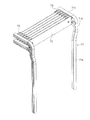
以下添付図面に基づいて、本発明の第一の実施形態におけるシャッタ装置を説明する。図1及び図2は、シャッタ装置の斜視図を示す。図1は、シャッタ装置の正面側の斜視図を示し、図2は、シャッタ装置の背面側の斜視図を示す。シャッタ装置は、平行に伸びる左右一対の案内レール1と、案内レール1に沿って移動する複数枚のスラット2と、を備える。案内レールは、建築物の開口部の左右両側の縁に沿って垂直方向に直線状に伸びる開口部区間1aと、開口部区間1aの上端部において、開口部の背面側に折れ曲がる繋ぎ区間1bと、繋ぎ区間1bから水平方向に直線状に伸びる収納部区間1cと、で構成される。案内レール1の収納部区間1c及び繋ぎ区間1bは、天井裏に隠されている(図4参照)。
Hereinafter, a shutter device according to a first embodiment of the present invention will be described with reference to the accompanying drawings. 1 and 2 are perspective views of the shutter device. FIG. 1 is a perspective view of the front side of the shutter device, and FIG. 2 is a perspective view of the back side of the shutter device. The shutter device includes a pair of left and
図1及び図2に示されるように、左右一対の案内レール1間には、複数枚のスラット2が掛け渡される。スラット2は薄板状で左右方向に細長く伸びる。複数枚のスラット2は互いに連結されておらず、それぞれが分離している。また、複数枚のスラット2それぞれは、左右で一対のブラケット3に取り付けられる。複数枚のスラットが開口部区間1aに移動したとき、複数枚のスラットはその表面が一平面に配置されるように配列される。スラット2の表面には、インテリアに適するように化粧が施される。複数枚のスラット2それぞれに同じ模様や色彩を施してもよいし、複数枚のスラット2を組み合わせたときに一つの模様が出来上がるようにしてもよい。
As shown in FIGS. 1 and 2, a plurality of
スラット2は、案内レール1やブラケット3等から構成される機能部品(金物)とは別の流通経路で供給されるのが望ましい。スラット2には、機能面よりもデザイン性が要求されるからである。
It is desirable that the
図3及び図4は、シャッタ装置を壁面の開口部に取り付けた例を示す。図3は、シャッタ装置の水平面内での断面図を示し、図4は、シャッタ装置の垂直面内での断面図を示す。図3に示されるように、シャッタ装置は凹ませた壁面4に取り付けられる。壁面4の開口部4aの左右両側には、シャッタ装置の厚みに応じた段差4bが形成される。段差4bの高さはシャッタ装置の高さに等しく、スラット2の表面と壁面4とは同一平面に(面一に)配置される。
3 and 4 show an example in which the shutter device is attached to the opening of the wall surface. 3 shows a cross-sectional view of the shutter device in the horizontal plane, and FIG. 4 shows a cross-sectional view of the shutter device in the vertical plane. As shown in FIG. 3, the shutter device is attached to the recessed
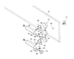
案内レール1は、段差4bにビス5等の結合手段を用いて結合される。案内レール1の断面形状は、四角形状である。四角形の正面側の一辺には、案内レール1に沿って細長く伸びるスリット6が形成される。このスリット6から断面L字状のブラケット本体7が突出する。案内レール1には、ブラケット本体7をはさんで二つのローラ案内通路8が形成される。二つのローラ案内通路8には、ブラケット本体7の両面に取り付けられる左右のローラ9が嵌められる。二つのローラ案内通路8の断面形状はローラ9の断面形状と略等しい。ブラケット本体7が案内レール1に沿って移動するとき、ローラ9の外周面がローラ案内通路8の対向する内壁面のいずれかに接触する。ローラ9の外周面は案内レール1によって囲まれているので、ブラケット本体7を案内レール1から開口部の正面側に抜き出すことはできない。
The
図5はブラケット本体7の詳細図を示す。図5(A)はブラケット本体7の正面図を示し、図5(B)はブラケット本体7の側面図を示す。ブラケット本体7の正面側の片11が、スラット2が取り付けられる取付け面となる。この正面側の片11には、雌ねじ11aが加工される。ブラケット本体7の側面側の片12には、ローラ9を取り付けるための三つのローラ取付け雌ねじ12a,12b,12cが加工される。上端と下端のローラ取付け雌ねじ12a,12cには正面側からローラ9が取り付けられ、中央のローラ取付け雌ねじ12bには、背面側からローラ9が取り付けられる。ブラケット本体7の左右両側に合計三つのローラ9を結合することで、ブラケット本体7の走行を安定させることができる(図7参照)。スラット2を上昇又は下降させたとき、ブラケット3の三つのローラ9の移動は案内レール1のローラ案内通路8に案内される(図4参照)。
FIG. 5 shows a detailed view of the
図6は止めねじ14を示す。止めねじ14は、雄ねじ14bと、頭部として円盤状のフランジ部14aと、を有する。図1に示されるように、スラット2には、止めねじ14の雄ねじ14bが貫通する貫通孔15が孔加工される。スラット2の貫通孔15に止めねじ14を通し、止めねじ14をブラケット3の雌ねじ11aに嵌め込むことで、スラット2をブラケット3の取付け面に取り付けることができる。また、ブラケット3からスラット2を取り外すときは、止めねじ14をブラケット3から取り外せばよい。ブラケット3へのスラット2の着脱は、ブラケット3を案内レール1に装着したまま行うことができる。
FIG. 6 shows the
図3に示されるように、スラット2が取り付けられるブラケット本体7の取付け面11は、案内レール1よりもシャッタ装置の正面側にはみ出している。そして、シャッタ装置の正面側から見て、スラット2の両端部が案内レール1を隠している。
As shown in FIG. 3, the mounting
図7は、ブラケット3の分解斜視図を示す。上述したように、複数枚のスラット2は互いに分離されている。スラット2を連動させて移動させるために、複数のブラケット3のうち、上下方向に隣接する一対のブラケット3は、連結部材17で連結されている。ローラ9は、ブッシュ18を介してブラケット本体7にねじ締めされる。連結部材17の上下方向の両端部には、ブッシュ18が貫通する貫通孔17aが開けられる。連結部材17はブラケット本体7に対して、ブッシュ18を中心にしてスラット2の表面と直交する平面内を回転する。これにより、連結させた一連のブラケット3を案内レール1に沿って移動させることができる。
FIG. 7 shows an exploded perspective view of the
スラット2は、手動により作動されても、電動により作動されてもよい。複数枚のスラット2の最下部の一枚を手で持って下降させれば、複数枚のスラット2が連動して下降するので、開口部を閉じることができる。一方、最下部の一枚のスラットを上昇させれば、複数枚のスラットが連動して上昇するので、開口部を開けることができる。開口部を開けたとき、複数枚のスラットは収納部区間1cまで移動しているので、天井裏内に隠れる。なお、収納部区間1cまで上昇した複数枚のスラット2は、開口部区間1aに下降しているときと同様に、一平面内に配列される。
The
スラット2を電動により作動させる方法としては、例えば最下部のスラット2にチェーン又はワイヤの一端を連結させて、電動モータによりチェーン又はワイヤを引き上げたり、引き下げたりする方法が考えられる。この他にも、案内レール1に沿ってラックを設け、ラックに噛合するピニオンをブラケットに取り付け、電動モータによりピニオンを回転させ、ラックアンドピニオン機構によりブラケットを上昇又は下降させる方法もある。
As a method of electrically operating the
図8ないし図10は、本発明の第二の実施形態におけるシャッタ装置を示す。図8は、正面側からみたシャッタ装置の斜視図を示し、図9は、正面側からみたシャッタ装置の分解斜視図を示し、図10は、背面側からみたシャッタ装置の分解斜視図を示す。この実施形態のシャッタ装置は、第一の実施形態のシャッタ装置と同様に、平行に伸びる左右一対の案内レール21と、案内レール21に沿って移動する複数のブラケット22と、複数のブラケットに支持される複数枚のスラット23と、を備える。
8 to 10 show a shutter device according to the second embodiment of the present invention. 8 shows a perspective view of the shutter device as seen from the front side, FIG. 9 shows an exploded perspective view of the shutter device as seen from the front side, and FIG. 10 shows an exploded perspective view of the shutter device as seen from the back side. As in the shutter device of the first embodiment, the shutter device of this embodiment is supported by a pair of left and right guide rails 21 extending in parallel, a plurality of
ブラケット22は、上記第一の実施形態のブラケット3のように分離されておらず、左右一対の案内レール21間に掛け渡されている。複数のブラケット22それぞれには、薄板状で左右方向に細長く伸びる複数枚のスラット23それぞれが取り付けられる。複数枚のスラット23は互いに連結されておらず、それぞれが分離している。スラット23、及びスラット23をブラケット22に取り付ける止めねじ24の構成は、上記第一の実施形態のシャッタ装置と同一である。
The
案内レール21は、建築物の開口部の左右両側の縁に沿って垂直方向に直線状に伸びる開口部区間21aと、開口部区間21aの上端部において、開口部の背面側に折れ曲がる繋ぎ区間21bと、繋ぎ区間21bから水平方向に直線状に伸びる収納部区間21cと、で構成される。案内レール21の収納部区間21c及び繋ぎ区間21bは、天井裏に隠されている(図12参照)。
The
図11及び図12は、シャッタ装置を壁面の開口部に取り付けた例を示す。図11は、開口部の水平面内での断面図を示し、図12は、シャッタ装置の垂直面内での断面図を示す。この実施形態では、図11に示されるように、凹ませた壁面26の対向する一対の側壁面26a間に、案内レール21が取り付けられる。一対の側壁面26a間の幅は、シャッタ装置の幅に等しい。スラット23が取り付けられるブラケット22の取付け面31は、案内レール21よりも開口部の正面側にはみ出している。スラット23の表面が壁面26と一平面内に(面一になるように)スラット23がブラケット22の取付け面31に取り付けられる。
11 and 12 show an example in which the shutter device is attached to the opening of the wall surface. FIG. 11 shows a sectional view of the opening in the horizontal plane, and FIG. 12 shows a sectional view in the vertical plane of the shutter device. In this embodiment, as shown in FIG. 11, the
図11に示されるように、案内レール21の断面形状は、四角形の一辺が取り除かれた断面コ字(C字)形状であり、底部27と底部27に直交する一対の側部28とで構成される。一対の案内レール21はその開口が向かい合っている。四角形状の案内レール21の内部空間が、ローラ案内通路29を構成する。ローラ案内通路29の断面形状は、ローラ30の断面形状と略等しい。ブラケット22が案内レール21に沿って移動するとき、ローラ30の外周面が案内レール21の対向する一対の側部28のいずれかに接触する。ローラ30の外周面は案内レール21で取り囲まれているので、案内レール21からローラ30を正面側に抜き出すことはできない。
As shown in FIG. 11, the cross-sectional shape of the
図13はブラケット22の分解斜視図を示す。ブラケット22は、左右一対の案内レール間に渡るブラケット本体32と、ブラケット本体32の左右の端部に回転可能に取り付けられるローラ30と、を有する。ブラケット本体32は、板状の台座34から一対の脚部33を突出させてなる。ブラケット本体32は、案内レール21間に左右方向に細長く伸びている。脚部33の長手方向の両端には、ブッシュ35を介してローラ30の軸部がねじ締めされる。この実施形態では一つのブラケット本体32に対して合計四つのローラ30が取り付けられる。
FIG. 13 is an exploded perspective view of the
上述したように、複数枚のスラット23は互いに分離されている。スラット23を連動させて移動させるために、複数のブラケット22のうち、上下方向に隣接する一対のブラケット22が、連結部材37で連結されている。連結部材37は薄板状で細長く伸びている。連結部材37の両端には、ブッシュ35が挿入される一対の貫通孔37aが開けられる。連結部材37はブラケット22に対して、ブッシュ35を中心にしてスラット23の表面と直交する平面内を回転できる。これにより、連結させた一連のブラケット22を案内レール21に沿って移動させることができる(図12参照)。
As described above, the plurality of
図14ないし図17は、本発明の第三の実施形態におけるシャッタ装置を示す。図14及び図15は、シャッタ装置の斜視図を示し、図16及び図17は、シャッタ装置の正面図を示す。図14及び図16は、複数枚のスラット42が案内レール41の下端側の開口部区間41aに移動して開口部が閉じられた状態を示し、図15及び図17は、複数枚のスラット42が案内レール41の上端側の収納部区間41cに移動して開口部が開けられた状態を示す。一対の案内レール41に複数枚のスラット42が掛け渡され、複数枚のスラット42が案内レール41に沿って移動して開口部が開閉される点は、上記第一及び第二の実施形態におけるシャッタ装置と同様である。しかし、この実施形態のシャッタ装置では、上記第一及び第二の実施形態におけるシャッタ装置と異なり、図15に示されるように、スラット42が収納部区間41cに移動したとき、複数枚のスラット42が互いに平行に並んだ状態で収納される。
14 to 17 show a shutter device according to the third embodiment of the present invention. 14 and 15 are perspective views of the shutter device, and FIGS. 16 and 17 are front views of the shutter device. 14 and 16 show a state in which the plurality of
図14及び図15に示されるように、この実施形態のシャッタ装置は、互いに平行に伸び、ブラケット43が移動するのを案内する左右一対の案内レール41と、一対の案内レール41に組みつけられ、一対の案内レール41に沿って移動できる複数のブラケット43と、一対の案内レール41間に掛け渡され、複数のブラケット43に支持される複数枚のスラット42と、を備える。左右一対の案内レール41には左右一対のブラケット43が装着され、左右一対のブラケット43に一枚のスラット42が支持される。複数枚のスラット42は互いに連結されていない。
As shown in FIGS. 14 and 15, the shutter device of this embodiment is assembled to a pair of left and right guide rails 41 that extend parallel to each other and guide the movement of the
図16に示されるように、複数枚のスラット42が案内レール41の下端側の開口部区間41aに移動したとき、案内レール41はスラット42の両端部の後方に隠れる。この開口部区間41aにおいて、一対の案内レール41の内法(内側の距離)は、スラット42の長手方向の長さよりも短い。その一方、図17に示されるように、複数枚のスラット42が収納部区間41cに移動したとき、複数枚のスラット42は一対の案内レール41間に挟まれる。この収納部区間41cにおいて、一対の案内レール41の内法は、スラット42の長手方向の長さよりも長い。スラット42の長手方向の長さは一定であるから、収納部区間41cにおける一対の案内レール41の内法は、開口部区間41aにおける一対の案内レール41の内法よりも大きい。
As shown in FIG. 16, when the plurality of
図18は、凹んだ壁面46に取り付けたシャッタ装置の水平方向断面図を示す。壁面46の開口部の左右両側には段差47が形成される。段差47の高さはシャッタ装置の高さに等しく、壁面46とスラット42の表面とは同一平面内に配置される。この図18には、案内レール41の断面図も示されている。案内レール41の断面形状は左右対称である。案内レール41には、その内部に長手方向に伸びる一条の主ローラ案内通路48と、二条の副ローラ案内通路49が形成される。主ローラ案内通路48は、案内レール41の中央部にかつ奥側に形成され、二条の副ローラ案内通路49は、案内レール41の左右両側にかつ手前側に形成される。主ローラ案内通路48には、ブラケット43の主ローラ56が転がり運動可能に収容され、副ローラ案内通路49にはブラケット43の副ローラ57が転がり運動可能に収容される。案内レール41の断面図において、主ローラ56の自転軸と副ローラ57の自転軸とは直交している。これにより、ブラケット43が案内レール41に沿って移動するとき、がたが生じることがない。
FIG. 18 shows a horizontal cross-sectional view of the shutter device attached to the recessed
図19は、案内レール41の側面図を示す。案内レール41は、開口部に配置され、垂直方向に直線状に伸びる開口部区間41aと、天井裏内に配置され、開口部区間41aの上端から垂直方向に伸びると共に、折れ曲がった後、二股に分かれて水平方向に伸びる繋ぎ区間41bと、天井裏内に配置され、繋ぎ区間41bの一端に接続される収納部区間41cとに分けられる。収納部区間41cにおいて、案内レール41は二股に分岐した状態で水平方向に直線状に伸びる。案内レール41を二股に分岐させたのは、スラット42を平行に配列した状態で収納するためである。
FIG. 19 shows a side view of the
図20は、案内レール41及びブラケット43の分解斜視図を示す。案内レール41は、シャッタ装置の正面からみて、開口部区間41aにおいて、スラット42の両端部の後方に配置される(図16参照)。その一方、案内レール41は、収納部区間41cにおいて、スラット42の長手方向の側方に配置される(図17参照)。これを実現するために、この実施形態の案内レール41は、繋ぎ区間41bにおいて90度ねじれている。図21は、ねじれた繋ぎ区間41bの案内レール41の断面形状の変化を示す。図21(C)に示されるように、スラット42の後方に配置される案内レール41が、ねじれることによって、図21(B),(A)に示されるように、除々にスラット42の長手方向の側方に位置するようになる。案内レール41から見れば、案内レール41の内側にスラット42が入ってくることになる。案内レール41のねじれの回転中心は、スラット42の背面に取り付けたブラケット43のヒンジ軸52である。
FIG. 20 shows an exploded perspective view of the
図20に示されるように、案内レール41はねじられた後、二股に分岐する。もともと一条の主ローラ案内通路48は、案内レール41の分岐に伴って二条の主ローラ案内通路48a,48bに分岐する。もともと二条の副ローラ案内通路49は、並列に並んだ状態から繋ぎ区間41bにおいて二股に分岐し、収納部区間41cにおいて二股に分岐した状態で直線状に伸びる。なお、この実施形態では、収納部区間41cにおいて、二股に分岐した案内レール41の形状を揃えるために、二股に分岐した案内レール41のそれぞれに二条の副ローラ案内通路が形成されているが、繋ぎ区間41bの副ローラ案内通路49に接続されるのは二条の副ローラ案内通路のうちの片側のみである。繋ぎ区間41bでの案内レール41は、ねじられ、かつ分岐されるので、全体が複数の分割ピースに分割される。分割ピースは止め金具53で連結される。
As shown in FIG. 20, the
ブラケット43は、スラット42が取り付けられるブラケット本体54と、案内レール41の長手方向に位置を異ならせてブラケット本体54に結合される二つの案内レール係合部55と、を有する。二つの案内レール係合部55の一方が二条の副ローラ案内通路49の一方に案内され、二つの案内レール係合部55の他方が二条の副ローラ案内通路49の他方に案内される。そして、収納部区間41cにおいて分岐した二つの案内レール41のうち、上側の案内レール41に上側の案内レール係合部55が案内され、下側の案内レール41に下側の案内レール係合部55が案内される。
The
案内レール係合部55は、ヒンジを介してブラケット本体54に結合される。案内レール係合部55は、案内レール41の主ローラ案内通路48に挿入される主ローラ56と、二条の副ローラ案内通路49の一方に収容される副ローラ57と、を有する。主ローラ56はヒンジ片59から突出させた主ローラ支持軸60に結合される。主ローラ56はこの主ローラ支持軸60を中心にして回転する。副ローラ57は主ローラ支持軸60にL字形状のアーム58を介して連結され、主ローラ支持軸60の回りを旋回(公転)する。
The guide
ブラケット本体54には、雌ねじ61が加工される。スラット42の、ブラケット本体54の雌ねじ61に対応する位置には貫通孔62が加工される。スラット42の貫通孔62に止めねじ63を通し、止めねじ63をブラケット本体54の雌ねじ61に嵌め込むことで、スラット42をブラケット本体54の取付け面に取り付けることができる。ブラケット本体54からスラット42を取り外すときは、止めねじ63をブラケット本体54から取り外せばよい。ブラケット本体54へのスラット42の着脱は、ブラケット43を案内レール41に装着したまま行うことができる。スラット42が取り付けられるブラケット本体54の取付け面65は、案内レール41よりもシャッタ装置の正面側にはみ出す。
A
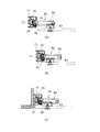
スラットが上昇すると、ブラケット43が開口部区間41aから繋ぎ区間41bに移行する。繋ぎ区間41bはねじれているので、図21に示されるように、案内レール41のねじれに対応するように、案内レール係合部55はヒンジ軸52を中心にヒンジ片59が開くように回転する。最終的には、ヒンジ片59は90度回転する。図22は、ねじれた繋ぎ区間を移動する案内レール係合部55を示す。ねじれた案内レール41に対応して、案内レール係合部55がヒンジ軸52を中心に回転しているのがわかる。
When the slat rises, the
図23は、さらにスラット42が繋ぎ区間41bを上昇した状態を示す。繋ぎ区間41bの案内レール41はねじれた後、二股に分岐する。分岐した二条の副ローラ案内通路49のうち、上側の副ローラ案内通路49に上側の案内レール係合部55の副ローラ57が導かれ、下側の副ローラ案内通路49に下側の案内レール係合部55の副ローラ57が導かれる。このように、副ローラ57は分岐後にどちらの副ローラ案内通路49に導かれるかが決まっている。主ローラ56は、分岐点において副ローラ57に引っ張られて二条に分岐した主ローラ案内通路48のいずれか一方に導かれる。
FIG. 23 shows a state where the
繋ぎ区間41bの案内レールは分岐後に折れ曲がっているので、これに対応できるように、副ローラ57は主ローラ支持軸60を中心にして旋回する。図24は収納部区間41cの垂直断面図を示す。図18の水平断面図に示されるように、開口部区間41aにおいては、副ローラ57の自転軸と主ローラ56の自転軸は水平面内に配置される。一方、図24に示されるように、収納部区間41cにおいては、アーム58が首を振って副ローラ57が90度旋回するので、副ローラ57の自転軸と主ローラ56の自転軸が垂直面内に配置される。
Since the guide rail in the connecting
図25は、案内レール41の収納部区間41cに収納された複数枚のスラット42を、シャッタ装置の背面側からみた斜視図である。収納部区間41cにおいて、上側の案内レール係合部55が上側の案内レール41に案内され、下側の案内レール係合部55が下側の案内レール41に案内される。そして、複数枚のスラット42は平行に配列される。また、ヒンジ片は90度開いていて、スラット42は一対の案内レール41の内側に挟まれる。
FIG. 25 is a perspective view of the plurality of
この実施形態でも、シャッタ装置のスラットを手動により作動させても、電動により作動させてもよい。手動により作動させる場合、複数枚のスラット42の一枚一枚を持って上昇又は下降させれば、開口部を開閉することができる。スラット42を電動により作動させる方法としては、案内レールに沿ってラックを設け、ラックに噛合するピニオンをブラケットに取り付け、電動モータによりピニオンを回転させ、ラックアンドピニオン機構によりブラケットを上昇又は下降させる方法が考えられる。この電動モータ・ピニオンは、全てのブラケット43に設けられてもよいし、最上端と最下端のブラケット43のみに設けてもよい。最上端と最下端のブラケット43のみに電動モータ・ピニオンを設ける場合、最下端のブラケット43に取り付けた駆動機構が全体を押し上げることになるし、複数枚のスラット42を下降させるときは、最上端のブラケット43に取り付けた駆動機構が全体を押し下げることになる。複数枚のスラットを上昇させるときでも下降させるときでも、電動モータを同期させる必要がある。この他にも、例えば最下部のスラットにチェーン又はワイヤの一端を連結させて、電動モータによりチェーン又はワイヤを引き上げたり、引き下げたりする機構も採用できる。
Also in this embodiment, the slats of the shutter device may be manually operated or electrically operated. In the case of manual operation, the opening can be opened and closed by raising or lowering each of the plurality of
図26ないし図29は、本発明の第四の実施形態におけるシャッタ装置を示す。図26及び図27は、シャッタ装置の斜視図を示し、図28及び図29は、シャッタ装置の正面図を示す。図26及び図28は、複数枚のスラット72が案内レール71の下端側の開口部区間71aに移動して開口部が閉じられた状態を示し、図27及び図29は、複数枚のスラット72が案内レール71の上端側の収納部区間71cに移動して開口部が開けられた状態を示す。この実施形態でも、第三の実施形態のシャッタ装置と同様に、スラット72が収納部区間71cに移動したとき、複数枚のスラット72が互いに平行に並んだ状態で収納される。
26 to 29 show a shutter device according to the fourth embodiment of the present invention. 26 and 27 show perspective views of the shutter device, and FIGS. 28 and 29 show front views of the shutter device. 26 and 28 show a state in which the plurality of
図26及び図27に示されるように、この実施形態のシャッタ装置は、互いに平行に伸びる一対の案内レール71と、一対の案内レール71に沿って移動するブラケット73と、一対の案内レール71間に掛け渡され、複数のブラケット73に支持される複数枚のスラット72と、を備える。複数枚のスラット72は互いに連結されていない。
As shown in FIGS. 26 and 27, the shutter device of this embodiment includes a pair of
図28に示されるように、複数枚のスラット72が案内レール71の下端側の開口部区間71aに移動したとき、案内レール71はスラット72の両端部の後方に隠れる。この開口部区間71aにおいて、一対の案内レール71の内法は、スラット72の長手方向の長さよりも短い。その一方、図29に示されるように、複数枚のスラット72が収納部区間71cに移動したとき、複数枚のスラット72は一対の案内レール71間に挟まれる。この収納部区間71cにおいて、一対の案内レール71の内法は、スラット72の長さ方向の長さよりも長い。スラット72の長手方向の長さは一定であるから、収納部区間71cにおける一対の案内レール71の内法は、開口部区間71aにおける一対の案内レール71の内法よりも大きい。
As shown in FIG. 28, when the plurality of
図30は、案内レール71の側面図を示す。案内レール71は、垂直方向に直線状に伸びる開口部区間71aと、開口部区間71aの上端から垂直方向に伸びると共に、折れ曲がった後、二股に分かれて水平方向に伸びる繋ぎ区間71bと、繋ぎ区間71bの一端に接続される収納部区間71cとに分けられる。収納部区間71cにおいて、案内レール71は二股に分岐した状態で水平方向に直線状に伸びる。収納部区間71cにおいて、案内レール71を二股に分岐させたのは、スラット72を平行に配列した状態で収納するためである。
FIG. 30 shows a side view of the
図31は、案内レール71の断面図を示す。案内レール71の断面形状は中心線を境にして左右対称である。案内レール71には、その内部に長手方向に伸びる一条の主ローラ案内通路77と、二条の副ローラ案内通路78が形成される。ブラケット73側からみて、主ローラ案内通路77は、案内レール71の中央部にかつ奥側に形成され、二条の副ローラ案内通路78は、案内レール41の左右両側にかつ手前側に形成される。主ローラ案内通路77には、後述するブラケット73の主ローラ79が転がり運動可能に収容され、副ローラ案内通路78にはブラケット73の副ローラ80が転がり運動可能に収容される。案内レール71の断面図において、主ローラ79の自転軸と副ローラ80の自転軸とは直交している。
FIG. 31 is a sectional view of the
上述したように、収納部区間71cにおける一対の案内レール71の内法は、開口部区間71aにおける一対の案内レール71の内法よりも大きい。そして、案内レール71は、シャッタ装置の正面からみて、開口部区間71aにおいて、スラット72の両端部の後方に配置される(図28参照)。その一方、案内レール71は、収納部区間71cにおいて、スラット72の長手方向の側方に配置される(図29参照)。これを実現するために、上記第三の実施形態のシャッタ装置では、案内レールを繋ぎ区間において90度ねじった。しかし、この実施形態のシャッタ装置では、案内レール71を繋ぎ区間71bにおいて、ねじることなく、開口部区間71aから収納部区間71cに向かって徐々に一対の案内レール71の内法を大きくしている。
As described above, the inner method of the pair of
図26に示されように、案内レール71は繋ぎ区間71bにおいて内法を広げた後、二股に分岐する。図30に示されるように、もともと一条の主ローラ案内通路77は、案内レール71の分岐に伴って二条の主ローラ案内通路77に分岐する。もともと二条の副ローラ案内通路78は、並列に並んだ状態から繋ぎ区間71bにおいて二股に分岐し、収納部区間71cにおいて二股に分岐した状態で直線状に伸びる。繋ぎ区間71bでの案内レール71は、ねじられ、かつ分岐するので、全体が複数の分割ピースに分割される。
As shown in FIG. 26, the
図32は、ブラケット73の分解斜視図を示す。ブラケット73は、スラット72が取り付けられるブラケット本体81と、案内レール71の長手方向に位置を異ならせてブラケット本体81に結合される二つの案内レール係合部82と、を有する。二つの案内レール係合部82の一方が二条の副ローラ案内通路78の一方に案内され、二つの案内レール係合部82の他方が二条の副ローラ案内通路78の他方に案内される。
FIG. 32 is an exploded perspective view of the
案内レール係合部82は、ブラケット本体81に回転可能に組み付けられる円盤状の回転体83と、回転体83に一軸方向にスライド可能に組みつけられるスライド体84と、スライド体84の端部の主ローラ支持軸85に結合される主ローラ79と、主ローラ支持軸85にL字形状のアーム86を介して連結される副ローラ80と、を有する。主ローラ79は主ローラ支持軸85を中心に回転する。副ローラ80は、主ローラ支持軸85の回りを旋回(公転)する。アーム86によって副ローラ80が旋回したとしても、副ローラ80の自転軸は主ローラ79の自転軸を通る。
The guide
図33は、スライド体84の詳細図を示す。スライド体84は半円柱形状であり、軸線方向に伸びる断面T字型のありみぞ88を有する。図32に示されるように、回転体83にはありみぞ88に嵌まる断面T字型の突起89が形成される。スライド体84は、回転体83の突起に案内されつつ一軸方向にスライドする。
FIG. 33 shows a detailed view of the
図32に示されるように、ブラケット本体81には、雌ねじが加工される。スラット72の、ブラケット本体81の雌ねじに対応する位置には貫通孔90が加工される。スラット72の貫通孔90に止めねじ91を通し、止めねじ91をブラケット本体81の雌ねじに嵌め込むことで、スラット72をブラケット本体81の取付け面に取り付けることができる。ブラケット本体81からスラット72を取り外すときは、止めねじ91をブラケット本体81から取り外せばよい。ブラケット73へのスラット72の着脱は、ブラケット73を案内レール71に装着したまま行うことができる。図31に示されるように、ブラケット本体81の取付け面92は、案内レール71よりもシャッタ装置の正面側にはみ出る。
As shown in FIG. 32, the bracket
図34は、繋ぎ区間71bの案内レール71を移動するブラケット73の形状の変化を示す。案内レール係合部82の主ローラ79は、案内レール71の主ローラ案内通路77に挿入され、副ローラ80は二条の副ローラ案内通路78の一方に挿入される。図34(C)に示されるように、スラット72が案内レール71の開口部区間71aを移動しているときは、スライド体84はスラット72の内方(図中右方向)に移動している。スラット72が上昇し、図34(B)に示される繋ぎ区間71bに入ると、上述したように一対の案内レール71の内法が除々に長くなるので、図34(A)に示されるように、案内レール71がスラット72から離間しようとする。案内レール71には主ローラ79及び副ローラ80が挿入されているので、案内レール71に引っ張られて、スライド体84が案内レール71側(図中左方向)にスライドする。
FIG. 34 shows a change in the shape of the
図35及び図36は、案内レール71に沿うブラケット73の移動を示す。図35(A)に示されるように、スラット72が案内レール71の開口部区間71aに位置するときは、上下二つのスライド体84は平行を保ち、最も内側(図中左方向)に位置する。図35(B)に示されるように、スラット72が繋ぎ区間71bに移動すると、上側のスライド体84は広がった案内レール71によって、案内レール71側に引っ張られる。案内レール71は傾いているので、案内レール71に対して直交しようとするスライド体84も傾く。スライド体84の回転は回転体83によって案内される。図36(A)に示されるように、さらにスラット72が上昇すると、上側のスライド体84は最も案内レール71側に移動し、分岐位置の手前まで移動する。ここでは、案内レール71は傾いていないので、スライド体84も水平を保つ。下側のスライド体84は徐々に案内レール71側に移動すると共に、傾いたレールにしたがって傾く。図36(B)に示されるように、スラット72がさらに上昇すると、上側の案内レール係合部82の主ローラ79は副ローラ80が上側の副ローラ案内通路78に導かれるのにしたがって、上側の主ローラ案内通路77に導かれる。一方、下側の案内レール係合部82の主ローラ79は副ローラ80が下側の副ローラ案内通路78に導かれるのにしたがって、下側の主ローラ案内通路77に導かれる。図36(C)に示されるように、スラット72が収納部区間71cに移動すると、上側の案内レール71に上側の案内レール係合部82が案内され、下側の案内レール71に下側の案内レール係合部82が案内される。これにより、収納部区間71cにおいて、複数枚のスラット72が平行を保つ。
35 and 36 show the movement of the
図37は、案内レール71の収納部区間71cの断面図を示す。スラット72が収納部区間71cに移動したとき、スライド体84は最も案内レール71側にスライドし、上下二つのスライド体84は平行を保つ。収納部区間71cにおいては、アーム86が首を振って副ローラ80が90度旋回するので、副ローラ80の自転軸と主ローラ79の自転軸が垂直面内に配置される。この実施形態でも、シャッタ装置のスラット72を手動により作動させても、電動により作動させてもよい。
FIG. 37 shows a cross-sectional view of the
なお、本発明は上記実施形態に限られることなく、本発明の要旨を変更しない範囲で種々変更が可能である。例えば、上記実施形態では、案内レールを垂直方向に伸びるように配置し、複数枚のスラットを縦方向(垂直方向)に移動させて開口部を開閉している。しかし、案内レールを水平方向に伸びるように配置し、複数枚のスラットを横方向(水平方向)に移動させて開口部を開閉してもよい。この場合、案内レールを一対設けなくても、上側のみにすることも考えられる。また、案内レールはシャッタ装置の正面側からみて背面側に折れ曲がっていても、正面側に折れ曲がっていてもよい。 The present invention is not limited to the above-described embodiment, and various modifications can be made without departing from the scope of the present invention. For example, in the above-described embodiment, the guide rails are arranged to extend in the vertical direction, and the openings are opened and closed by moving a plurality of slats in the vertical direction (vertical direction). However, the guide rail may be arranged to extend in the horizontal direction, and the opening may be opened and closed by moving a plurality of slats in the horizontal direction (horizontal direction). In this case, it is conceivable that only one guide rail is provided on the upper side without providing a pair. Further, the guide rail may be bent to the back side or the front side as viewed from the front side of the shutter device.
本明細書は、2006年9月12日出願の特願2006−246462に基づく。この内容はすべてここに含めておく。 This specification is based on Japanese Patent Application No. 2006-246462 filed on Sep. 12, 2006. All this content is included here.
Claims (8)
前記一対の案内レールの案内通路に沿って移動できるように、前記一対の案内レールに組み付けられる複数のブラケットと、
前記一対の案内レール間に掛け渡され、前記複数のブラケットに支持される複数枚のスラットと、を備え、
前記複数枚のスラットは、前記一対の案内レールの長手方向の一端側に移動したとき、前記複数枚のスラットの表面が略同一の平面内に配列されると共に、シャッタ装置の正面側から見たとき、前記複数枚のスラットの長手方向の両端部で前記一対の案内レールを隠し、
前記複数枚のスラットは、互いに連結されておらず、
そして、前記ブラケットを前記案内レールに装着したまま、前記ブラケットから前記スラットを一枚毎着脱できることを特徴とするシャッタ装置。A pair of guide rails extending parallel to each other;
A plurality of brackets assembled to the pair of guide rails so as to be movable along the guide paths of the pair of guide rails;
A plurality of slats spanned between the pair of guide rails and supported by the plurality of brackets;
When the plurality of slats move to one end side in the longitudinal direction of the pair of guide rails, the surfaces of the plurality of slats are arranged in substantially the same plane and viewed from the front side of the shutter device. when hides the pair of guide rails at both longitudinal ends of said plurality of slats,
The plurality of slats are not connected to each other,
The shutter device is characterized in that each of the slats can be attached to and detached from the bracket while the bracket is attached to the guide rail.
前記スラットの、前記ブラケットの前記雌ねじに対応する位置には貫通孔が加工され、
前記スラットの前記貫通孔に頭部を有する止めねじを通し、前記止めねじを前記ブラケットの前記雌ねじに嵌め込むことで、前記スラットが前記ブラケットに取り付けられることを特徴とする請求項1ないし5のいずれかに記載のシャッタ装置。The bracket is machined with an internal thread,
In the slat, a through hole is processed at a position corresponding to the female screw of the bracket,
6. The slat is attached to the bracket by passing a set screw having a head through the through hole of the slat and fitting the set screw into the female screw of the bracket. The shutter device according to any one of the above.
前記一対の案内レールの案内通路に沿って移動できるように、前記一対の案内レールに組み付けられる複数のブラケットと、を備え、
前記複数のブラケットは、前記一対の案内レール間に掛け渡されると共に、互いに連結されていない複数枚のスラットを支持でき、
前記複数のブラケットは、前記一対の案内レールの長手方向の一端側に移動したとき、前記複数枚のスラットの表面を略同一の平面内に配列させることができると共に、シャッタ装置の正面側から見たとき、前記複数枚のスラットの長手方向の両端部で前記一対の案内レールを隠すことができ、
そして、前記ブラケットを前記案内レールに装着したまま、前記ブラケットから前記スラットを一枚毎着脱できることを特徴とするシャッタ装置用金物。A pair of guide rails extending parallel to each other;
A plurality of brackets assembled to the pair of guide rails so as to be movable along the guide passages of the pair of guide rails;
The plurality of brackets are supported between the pair of guide rails and can support a plurality of slats that are not connected to each other.
When the plurality of brackets move to one end side in the longitudinal direction of the pair of guide rails, the surfaces of the plurality of slats can be arranged in substantially the same plane and viewed from the front side of the shutter device. when in can be in the longitudinal ends of said plurality of slats hiding the pair of guide rails,
And the hardware for a shutter device, wherein each of the slats can be attached to and detached from the bracket while the bracket is attached to the guide rail.
Priority Applications (1)
| Application Number | Priority Date | Filing Date | Title |
|---|---|---|---|
| JP2007542175A JP4778971B2 (en) | 2006-09-12 | 2007-08-23 | Shutter device and hardware for shutter device |
Applications Claiming Priority (4)
| Application Number | Priority Date | Filing Date | Title |
|---|---|---|---|
| JP2006246462 | 2006-09-12 | ||
| JP2006246462 | 2006-09-12 | ||
| PCT/JP2007/066398 WO2008032541A1 (en) | 2006-09-12 | 2007-08-23 | Shutter device and hardware for shutter device |
| JP2007542175A JP4778971B2 (en) | 2006-09-12 | 2007-08-23 | Shutter device and hardware for shutter device |
Publications (2)
| Publication Number | Publication Date |
|---|---|
| JPWO2008032541A1 JPWO2008032541A1 (en) | 2010-01-21 |
| JP4778971B2 true JP4778971B2 (en) | 2011-09-21 |
Family
ID=39183606
Family Applications (1)
| Application Number | Title | Priority Date | Filing Date |
|---|---|---|---|
| JP2007542175A Expired - Fee Related JP4778971B2 (en) | 2006-09-12 | 2007-08-23 | Shutter device and hardware for shutter device |
Country Status (2)
| Country | Link |
|---|---|
| JP (1) | JP4778971B2 (en) |
| WO (1) | WO2008032541A1 (en) |
Families Citing this family (3)
| Publication number | Priority date | Publication date | Assignee | Title |
|---|---|---|---|---|
| JP4699318B2 (en) * | 2006-09-12 | 2011-06-08 | スガツネ工業株式会社 | Shutter device and hardware for shutter device |
| JP6281298B2 (en) * | 2014-01-28 | 2018-02-21 | 富士通株式会社 | Information processing apparatus and replacement parts |
| US20230374836A1 (en) * | 2022-05-23 | 2023-11-23 | Cornellcookson, Llc | Vertically stacking panel door with improved curved track portions |
Citations (3)
| Publication number | Priority date | Publication date | Assignee | Title |
|---|---|---|---|---|
| JPS62177844A (en) * | 1986-01-31 | 1987-08-04 | Hitachi Ltd | Penta-shaft manipulator |
| JPH05169976A (en) * | 1991-08-21 | 1993-07-09 | Daikyo Webasto Co Ltd | Vehicle roof incorporating slat lattice |
| JP2006152654A (en) * | 2004-11-29 | 2006-06-15 | Nifco Inc | Shutter for door |
Family Cites Families (4)
| Publication number | Priority date | Publication date | Assignee | Title |
|---|---|---|---|---|
| JPS6153982A (en) * | 1984-04-20 | 1986-03-18 | 株式会社 清弘エンジニアリング | Transparent shutter |
| JPS60194093U (en) * | 1984-05-31 | 1985-12-24 | トヨタ自動車株式会社 | Overhead shutter |
| JPS62124192U (en) * | 1986-01-28 | 1987-08-06 | ||
| JPH0243964Y2 (en) * | 1986-05-02 | 1990-11-21 |
-
2007
- 2007-08-23 JP JP2007542175A patent/JP4778971B2/en not_active Expired - Fee Related
- 2007-08-23 WO PCT/JP2007/066398 patent/WO2008032541A1/en active Application Filing
Patent Citations (3)
| Publication number | Priority date | Publication date | Assignee | Title |
|---|---|---|---|---|
| JPS62177844A (en) * | 1986-01-31 | 1987-08-04 | Hitachi Ltd | Penta-shaft manipulator |
| JPH05169976A (en) * | 1991-08-21 | 1993-07-09 | Daikyo Webasto Co Ltd | Vehicle roof incorporating slat lattice |
| JP2006152654A (en) * | 2004-11-29 | 2006-06-15 | Nifco Inc | Shutter for door |
Also Published As
| Publication number | Publication date |
|---|---|
| WO2008032541A1 (en) | 2008-03-20 |
| JPWO2008032541A1 (en) | 2010-01-21 |
Similar Documents
| Publication | Publication Date | Title |
|---|---|---|
| JP4818362B2 (en) | Sliding door | |
| JP6211700B2 (en) | Assembled safety door | |
| JP4778971B2 (en) | Shutter device and hardware for shutter device | |
| KR100823663B1 (en) | Transparency closing type's curtain wall structure with sliding window | |
| JP4699318B2 (en) | Shutter device and hardware for shutter device | |
| WO2009139016A2 (en) | Sliding door with variable dimensions | |
| JP5373646B2 (en) | Driving device, opening / closing device, and opening device including the opening / closing device | |
| JP5529864B2 (en) | Door assembly | |
| JP4569318B2 (en) | Elevator equipment | |
| KR20170106850A (en) | Folding door structure | |
| JP2008038399A (en) | Sliding door | |
| JP4850093B2 (en) | Sliding door guide structure | |
| JP2009228355A (en) | Movable partition panel | |
| JP2008025212A (en) | Vestibule door with transom | |
| JP2021085291A (en) | Opening/closing body | |
| KR102672969B1 (en) | Two way folding door | |
| JP2001303873A (en) | Closing device | |
| JP2009019466A (en) | Flat sliding door | |
| JP6580952B2 (en) | Partition storage unit | |
| JP2008025213A (en) | Vestibule door with wing panel | |
| JP6888184B2 (en) | Switchgear and its construction method | |
| JP5796196B2 (en) | Entrance structure | |
| JP5118357B2 (en) | Storage structure | |
| JP6545027B2 (en) | Burial altar | |
| JP2004132001A (en) | Sliding door |
Legal Events
| Date | Code | Title | Description |
|---|---|---|---|
| A131 | Notification of reasons for refusal |
Free format text: JAPANESE INTERMEDIATE CODE: A131 Effective date: 20100907 |
|
| A521 | Request for written amendment filed |
Free format text: JAPANESE INTERMEDIATE CODE: A523 Effective date: 20101104 |
|
| A131 | Notification of reasons for refusal |
Free format text: JAPANESE INTERMEDIATE CODE: A131 Effective date: 20110406 |
|
| A521 | Request for written amendment filed |
Free format text: JAPANESE INTERMEDIATE CODE: A523 Effective date: 20110603 |
|
| TRDD | Decision of grant or rejection written | ||
| A01 | Written decision to grant a patent or to grant a registration (utility model) |
Free format text: JAPANESE INTERMEDIATE CODE: A01 Effective date: 20110628 |
|
| A01 | Written decision to grant a patent or to grant a registration (utility model) |
Free format text: JAPANESE INTERMEDIATE CODE: A01 |
|
| A61 | First payment of annual fees (during grant procedure) |
Free format text: JAPANESE INTERMEDIATE CODE: A61 Effective date: 20110704 |
|
| R150 | Certificate of patent or registration of utility model |
Free format text: JAPANESE INTERMEDIATE CODE: R150 |
|
| FPAY | Renewal fee payment (event date is renewal date of database) |
Free format text: PAYMENT UNTIL: 20140708 Year of fee payment: 3 |
|
| LAPS | Cancellation because of no payment of annual fees | ||
| A621 | Written request for application examination |
Free format text: JAPANESE INTERMEDIATE CODE: A621 Effective date: 20071114 |