JP4776552B2 - Communication terminal, calculated ID output device, network start server, communication network system - Google Patents
Communication terminal, calculated ID output device, network start server, communication network system Download PDFInfo
- Publication number
- JP4776552B2 JP4776552B2 JP2007004236A JP2007004236A JP4776552B2 JP 4776552 B2 JP4776552 B2 JP 4776552B2 JP 2007004236 A JP2007004236 A JP 2007004236A JP 2007004236 A JP2007004236 A JP 2007004236A JP 4776552 B2 JP4776552 B2 JP 4776552B2
- Authority
- JP
- Japan
- Prior art keywords
- network
- identification
- calculated
- communication
- calculation
- Prior art date
- Legal status (The legal status is an assumption and is not a legal conclusion. Google has not performed a legal analysis and makes no representation as to the accuracy of the status listed.)
- Expired - Fee Related
Links
Images


Landscapes
- Small-Scale Networks (AREA)
- Mobile Radio Communication Systems (AREA)
Description
本発明は、識別IDで識別されるネットワーク上で稼動する通信端末、算出ID出力器、ネットワーク開始サーバ、及びこれらを有する通信ネットワークシステムに関するものである。 The present invention relates to a communication terminal operating on a network identified by an identification ID, a calculated ID output device, a network start server, and a communication network system having these.
従来、『ハウスコードを設定する際に、通信装置に対する入力操作や結線の変更を不要にして、ハウスコードの設定を簡単に行うことができるハウスコード設定方法および通信システムを提供する。』ことを目的とした技術として、『設定装置1は、ハウスコードを入力するための入力部と、入力されたハウスコードを記憶する第1記憶部と、ハウスコードを設定するとき、第1記憶部から読み出したハウスコードを送る第1制御部と、第1制御部からのハウスコードを無線で送信する送信部とを備え、通信装置2、3は、無線で送られてくるハウスコードを受信する受信部と、受信部からのハウスコードを記憶する第2記憶部と、その後、電灯線から受信したハウスコードが第2記憶部に記憶されているハウスコードと一致するとき、ハウスコードと共に送信される、電灯線からの信号を受信する第2制御部とを備える。』というものが提案されている(特許文献1)。
また、『電灯線通信システムにおいて煩わしい動作を省き、隣家からのデータの混信が存在する場合にも誤りなくハウスコードやアドレスを設定する。』ことを目的とした技術として、『電灯線100を介して複数の装置間でデータ通信を行う通信ネットワークシステムにおける、被制御端末nと、被制御端末nに前記ハウスコードおよびアドレスの設定を行う制御端末2とを備え、ハウスコードアナウンスデータおよびアドレス設定データに基づき、被制御端末nにハウスコードおよびアドレスを設定する。』というものも提案されている(特許文献2)。
Conventionally, “a house code setting method and a communication system that can easily perform setting of a house code without requiring an input operation to the communication device or a change in connection when setting the house code are provided. As a technology for the purpose, “the
Further, “a troublesome operation in the power line communication system is omitted, and the house code and address are set without error even when there is data interference from a neighbor. As a technology for the purpose of the above, “in the communication network system for performing data communication between a plurality of devices via the
通信端末によってネットワークを形成する場合、同一の通信媒体上に、同一のプロトコルを持つ複数の異なるネットワークに属する通信端末が共存する場合がある。これらの通信端末に対して、混信を防止するために、ネットワークごとに識別IDを割り振る。
あるネットワークに属する通信端末は、同じ識別IDを使用して通信する必要がある。したがってすべての通信端末に対して、あらかじめ識別IDを指定する必要がある。
When a network is formed by communication terminals, communication terminals belonging to a plurality of different networks having the same protocol may coexist on the same communication medium. In order to prevent interference with these communication terminals, an identification ID is assigned to each network.
Communication terminals belonging to a certain network need to communicate using the same identification ID. Therefore, it is necessary to specify an identification ID in advance for all communication terminals.
識別IDは、共存するネットワークの数によってその範囲の大きさが決まる。混信を防止するためには広い識別空間が必要となるため、識別IDは長くなる。
それゆえ、全てのコードをスイッチなどにより正確に入力することは煩雑であり、また誤りなく入力することは、一般ユーザにとって難しい。特に組み込み機器などでは、部品の大きさの制約が厳しく、必然的にスイッチを小さくする必要がある。このような小さいスイッチの設定は、ユーザにとってさらに困難である。
The size of the identification ID is determined by the number of coexisting networks. Since a wide identification space is required to prevent interference, the identification ID becomes long.
Therefore, it is troublesome to input all codes accurately by using a switch or the like, and it is difficult for general users to input without error. Especially in embedded devices and the like, the size restrictions of parts are severe, and it is necessary to make the switch small. Setting such a small switch is even more difficult for the user.
この点に関し、特許文献1に記載の従来技術によれば、ハウスコードの設定を行う通信装置自体の認証や、その装置自体への識別IDの入力の手間、といった課題が残る。
また、特許文献2に記載の従来技術は、同一の通信媒体上にネットワークが複数共存する環境下においてはうまく機能しないという課題がある。
本発明は、上記のような課題を解決するためになされたもので、ユーザが通信端末にネットワークの識別IDを設定する手間を軽減し、設定誤りを少なくすることのできる通信端末、算出ID出力器、ネットワーク開始サーバ、通信ネットワークシステムを提供することを目的とする。
In this regard, according to the prior art described in
Moreover, the prior art described in Patent Document 2 has a problem that it does not function well in an environment where a plurality of networks coexist on the same communication medium.
The present invention has been made in order to solve the above-described problems. A communication terminal and a calculation ID output that can reduce the trouble of setting a network identification ID in a communication terminal and reduce setting errors. It is an object to provide a communication device, a network start server, and a communication network system.
本発明に係る通信端末は、
参加するネットワークの識別IDを指定してそのネットワークに参加する通信端末であって、
ネットワークとの間で通信パケットの送受信を行う通信手段と、
ネットワークの識別IDよりも桁数の少ない指定IDを入力する入力手段と、
ネットワークの識別IDに基づき、所定の第1演算式を用いて算出IDを計算する計算手段と、
を備え、
前記通信手段は、
近隣に存在する各ネットワークの識別IDを通信パケットから取得し、
前記計算手段は、
前記通信手段が取得した各ネットワークの識別ID毎に前記算出IDを計算し、
計算した算出IDと、前記入力手段へ入力された指定IDとが一致するネットワークに参加するように、前記通信手段に指示を出し、
前記通信手段が取得した各ネットワークの識別ID毎に前記算出IDを計算した際に、
計算した算出IDと、前記入力手段へ入力された指定IDとが一致するネットワークが複数存在する場合には、
それらのうちいずれかのネットワークに参加し、参加に失敗した際には、次のネットワークに参加するように、前記通信手段に指示を出す
ことを特徴とするものである。
A communication terminal according to the present invention includes:
A communication terminal that specifies an identification ID of a network to participate in and participates in the network,
A communication means for transmitting and receiving communication packets to and from the network;
An input means for inputting a designated ID having a smaller number of digits than the identification ID of the network;
Calculation means for calculating a calculated ID using a predetermined first arithmetic expression based on the identification ID of the network;
With
The communication means includes
Obtain the identification ID of each network in the neighborhood from the communication packet,
The calculating means includes
Calculating the calculated ID for each network identification ID acquired by the communication means;
A calculated calculation ID, as the specified ID inputted to the input means to participate in the matching network, and exits the instruction to the communication means,
When calculating the calculated ID for each network identification ID acquired by the communication means,
When there are a plurality of networks in which the calculated ID and the specified ID input to the input means match,
When one of them joins a network and fails to join, the communication means is instructed to join the next network .
本発明に係る通信端末によれば、ユーザはネットワーク識別IDよりも短いIDを設定するだけで通信端末の参加先ネットワークを指定することができ、ユーザの手間を軽減できるとともに、設定誤りを少なくすることができる。 According to the communication terminal according to the present invention, the user can specify the destination network of the communication terminal only by setting an ID shorter than the network identification ID, which can reduce the trouble of the user and reduce setting errors. be able to.
実施の形態1.
図1は、本発明の実施の形態1に係る通信ネットワークシステムの概略構成を示すものである。ここでは、ホームネットワークを例に取り、以下の説明を行う。
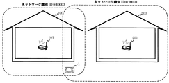
図1において、隣接する家屋100と家屋200は、それぞれ屋内にホームサーバ101と201を設置し、ホームネットワークを形成している。
家屋100内のホームサーバ101が形成するホームネットワークは、ネットワーク識別IDの値が「40003」に設定されており、同様に家屋200内のホームサーバ201が形成するホームネットワークは、ネットワーク識別IDの値が「20001」に設定されている。これらの識別IDの値は、ホームサーバ101及び102が任意に定めたものである。
両者のホームネットワークは、無線ネットワークにより形成されており、その領域の一部は互いに重複している。即ち、この重複領域に存在する通信端末は、双方のホームネットワークに参加し得る状態にあることになる。
図1において、通信端末1は、上述の重複領域に存在しているものとする。
FIG. 1 shows a schematic configuration of a communication network system according to
In FIG. 1,
The home network formed by the
Both home networks are formed by wireless networks, and some of the areas overlap each other. That is, the communication terminal existing in this overlapping area is in a state where it can participate in both home networks.
In FIG. 1, it is assumed that the
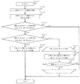
図2は、従来のネットワーク参加手順を示すものである。
図1のネットワーク構成において、従来のネットワーク参加手順では、通信端末1は、以下のステップによりホームネットワークに参加する。
(1)識別IDのセット
ユーザが通信端末1の識別ID設定スイッチを操作するなどして、通信端末1のネットワーク識別IDをセットする。ここでは、ホームサーバ101のホームネットワークに参加するものとし、ユーザは「識別ID=40003」にセットする。
(2)接続試行
通信端末1は、セットされたネットワーク識別IDを用いて、双方のホームネットワークへの参加を試みる。ここでは、ネットワーク識別IDが自己の設定値「40003」と一致する、ホームサーバ101のホームネットワークに参加することとなる。
FIG. 2 shows a conventional network participation procedure.
In the network configuration of FIG. 1, in the conventional network participation procedure, the
(1) Set identification ID The user operates the identification ID setting switch of the
(2) Connection attempt The
図2の従来手順によるネットワーク参加において、ユーザは通信端末1の識別ID設定スイッチを操作するなどしなければならないが、既に述べた通りこれは煩雑な作業であり、また設定誤りを起こす可能性もあるという課題がある。
例えば、「識別ID=40003」は、2進数であれば16桁の設定が必要であり、ユーザにとっては煩雑な作業である。
In the network participation according to the conventional procedure of FIG. 2, the user must operate the identification ID setting switch of the
For example, if “identification ID = 40003” is a binary number, it is necessary to set 16 digits, which is a complicated operation for the user.
図3は、本発明におけるネットワーク参加手順の概略を示すものである。
本発明においては、ネットワークの識別IDはユーザの目に触れさせず、これに替えて桁数の少ないID(以下、指定IDと呼ぶ)をユーザに設定させ、通信端末1の内部でネットワーク識別IDに変換して参加に用いる。
以下、ネットワーク参加手順の各ステップについて概略を説明する。
FIG. 3 shows an outline of the network participation procedure in the present invention.
In the present invention, the network identification ID is not touched by the user, and instead, an ID with a small number of digits (hereinafter referred to as a designated ID) is set by the user, and the network identification ID is set inside the
The outline of each step of the network participation procedure will be described below.
(1)算出IDを通知
ホームサーバ101は、ネットワーク識別ID「40003」でネットワークを開始する。次に、この識別IDの値を所定の演算式で変換した値を、算出IDとして求める。本実施の形態1では、識別IDの値を16で除算した剰余を、算出IDとして求めるものとする。
求めた算出IDは、LEDディスプレイによる画面表示などのユーザが確認できる方法で通知する。ここでは、「算出ID=3」を通知することになる。
(2)指定IDをセット
ユーザは、通信端末1の指定ID設定スイッチを操作するなどして、通信端末1の指定IDを、ホームサーバ101が通知した値と同じになるように、「指定ID=3」にセットする。
指定IDは16の剰余であるため、最大値が15となり、2進数であれば最大でも4桁の設定を行えばよく、従来と比較して大幅に設定の手間が軽減される。
(3)各ネットワークの算出IDを計算
通信端末1は、近隣に存在するネットワークの通信パケットから、そのネットワークの識別IDを検出し、それぞれを16で除算した剰余を計算して算出IDを求める。
図3の例では、ホームサーバ101配下のネットワークは「識別ID=40003」であるため、「算出ID=3」であることが分かる。また、ホームサーバ201配下のネットワークは「識別ID=20001」であるため、「算出ID=1」であることが分かる。
(4)自己の指定ID(=3)と一致するネットワークに参加
通信端末1は、指定ID設定スイッチで設定された指定ID(=3)と、計算した算出IDとが一致するネットワークに参加する。ここでは、ステップ(2)でユーザが設定した「指定ID=3」に一致する、ホームサーバ101配下のネットワークに参加することになる。
(1) Notification of calculation ID The
The calculated ID obtained is notified by a method that can be confirmed by the user, such as a screen display by an LED display. Here, “calculation ID = 3” is notified.
(2) Set designated ID The user operates the designated ID setting switch of the
Since the specified ID is a remainder of 16, the maximum value is 15, and if it is a binary number, it is sufficient to set a maximum of 4 digits, and the setting labor is greatly reduced as compared with the conventional case.
(3) Calculation of calculation ID of each network The
In the example of FIG. 3, since the network under the
(4) Participating in a network that matches its own designated ID (= 3) The
図3で説明したネットワーク参加手順によれば、ユーザは少ない桁数の設定で参加先ネットワークを指定することができるので、従来の参加手順と比較して手間が大幅に削減される。
また、ホームサーバ101があらかじめ自己の算出ID(=3)をユーザに通知しているので、通信端末1が参加先ネットワークを誤ることもない。
According to the network participation procedure described with reference to FIG. 3, the user can designate the participation destination network with a setting of a small number of digits, so that labor is greatly reduced compared to the conventional participation procedure.
Further, since the
以上は、本発明におけるネットワーク参加手順の概略を説明したが、次に通信端末1の構成と、より詳細な動作について説明する。
The outline of the network participation procedure in the present invention has been described above. Next, the configuration and more detailed operation of the
図4は、本実施の形態1に係る通信端末210の構成を示すブロック図である。
図4の通信端末210は、図3で説明した通信端末1と同じ構成を有し、通信手段202、入力手段204、計算手段206を備える。
通信手段202は、有線又は無線のネットワーク接続インターフェースを備え、参加先のネットワークとの間で通信パケットの送受信を行う。また、通信パケットの送受信の際には、参加先ネットワークの識別ID203を併せて送受信する。その他、近隣ネットワークの通信パケットからそのネットワークの識別IDを検出して取り出す機能を持つ。
入力手段204は、通信端末210の本体筐体外面に設けられたディップスイッチやロータリースイッチなどの電気的接点を有するスイッチからなり、そのスイッチにより設定された指定ID205を保持する。
計算手段206は、通信手段202が近隣ネットワークの通信パケットからそのネットワークの識別IDを検出した際に、その識別IDの値から、図3で説明した所定の演算式を用いて算出ID207を計算する。
FIG. 4 is a block diagram showing a configuration of
A
The
The
When the
図5は、本実施の形態1に係る通信端末210がネットワークに参加する際の動作フローである。以下、各ステップについて説明する。
(S501)
通信端末210が、ネットワーク参加手順を開始する。
(S502)
通信手段202は、近隣に存在するネットワークの識別IDを取得し、計算手段206に通知する。
(S503)
計算手段206は、通信手段202から受け取った識別ID毎に、所定の演算式を用いて算出IDを計算する。所定の演算式とは、例えば図3で説明したように、16で除算した剰余を求める演算などのことである。
本実施の形態1における「第1演算式」は、この16で除算した剰余を求める演算がこれに該当する。
(S504)
計算手段206は、ステップS503で計算した算出IDと、入力手段204で設定された指定IDとを比較する。
ステップS503で計算した算出IDの中で、入力手段204で設定された指定IDと一致するものがあればステップS505へ進み、一致するものがなければ、ネットワーク参加処理を終了する。
(S505)
計算手段206は、ステップS503で計算した算出IDの中で、入力手段204で設定された指定IDと一致するものが何個あるかを判定する。
一致するものが1つであればステップS506へ進み、2つ以上あればステップS507へ進む。
(S506)
計算手段206は、ステップS503で計算した算出IDの基になったネットワーク識別IDを自己の識別ID203とし、その識別IDに対応するネットワークに参加するように、通信手段202へ指示を出す。
通信手段202は、計算手段206から指示された識別IDを用いて、対応するネットワークに参加する。
(S507)
計算手段206は、ステップS505において、ステップS503で計算した算出IDの中で、入力手段204で設定された指定IDと一致するものとして得られた個数と同じ回数、次のステップS508〜S509の処理を繰り返す。
(S508)
計算手段206は、ステップS503で計算した算出IDの基になったネットワーク識別IDを自己の識別ID203とし、その識別IDに対応するネットワークに順次参加するように、通信手段202へ指示を出す。
通信手段202は、計算手段206から指示された識別IDを用いて、対応するネットワークに参加する。
(S509)
通信手段202は、参加したネットワークの通信パケットなどから、そのネットワークの属性情報を検出し、計算手段206に通知する。
計算手段206は、通信手段202から受け取ったネットワークの属性情報を基に、そのネットワークが参加したいネットワークであるか否かを判定する。
そのネットワークが参加したいネットワークであれば、そのままそのネットワークに参加して処理を終了する。参加したいネットワークでなければ、ステップS508に戻って繰り返し処理を継続する。
ここで、ネットワークから得られる属性情報としては、例えば、ネットワーク機器のカンパニーコード、タイムスタンプ、バージョン情報、通信プロトコルなどがある。
参加したいネットワークであるか否かを判断する基準としては、例えば参加予定のネットワークが設備機器ネットワークであれば、以下のようなものが考えられる。
(1)そのネットワークで用いられている通信プロトコルが設備機器管理に用いられるプロトコルであるか否かを基準とする。
(2)ネットワーク機器の製品コードが、設備機器に割り当てられるものであるか否かを基準とする。
FIG. 5 is an operation flow when the
(S501)
The
(S502)
The
(S503)
The
The “first arithmetic expression” in the first embodiment corresponds to an operation for obtaining a remainder obtained by dividing by 16.
(S504)
The
If the calculated ID calculated in step S503 matches the specified ID set by the input means 204, the process proceeds to step S505, and if there is no match, the network participation process ends.
(S505)
The
If there is one match, the process proceeds to step S506, and if there are two or more, the process proceeds to step S507.
(S506)
The
The
(S507)
In step S505, the
(S508)
The
The
(S509)
The
Based on the network attribute information received from the
If the network is a network that the user wants to join, the network joins the network as it is, and the process ends. If it is not the network to join, the process returns to step S508 and the process is repeated.
Here, the attribute information obtained from the network includes, for example, a company code of a network device, a time stamp, version information, a communication protocol, and the like.
As a reference for determining whether or not the network is a network to be joined, for example, if the network scheduled to participate is an equipment network, the following may be considered.
(1) Based on whether the communication protocol used in the network is a protocol used for equipment management.
(2) Based on whether the product code of the network device is assigned to the facility device.
ステップS509における、ネットワークに参加するか否かの基準は、通信端末210の工場出荷時にROMに書き込んでおいてもよいし、別途ユーザが設定する手段を設けてもよい。後者の場合は、仮に間違ったネットワークに接続してしまったとしても、接続するネットワークをユーザ自身が正すことができる。
また、ステップS509において、参加したいネットワークであるか否かによる基準だけでなく、参加試行が成功するか否かで判断してもよい。特に、参加先のネットワークにおいて、参加可能な端末を限定している場合には、実際に参加試行してみるほうが、参加可否の判断が容易である。
The criterion for determining whether or not to participate in the network in step S509 may be written in the ROM when the
Further, in step S509, determination may be made based on whether or not the participation trial is successful, as well as the criterion based on whether or not the network is desired to participate. In particular, in the participation destination network, when terminals that can participate are limited, it is easier to determine whether or not to participate by actually trying to participate.
以上のように、本実施の形態1によれば、ユーザはネットワーク識別IDよりも短い指定IDを設定するだけで通信端末の参加先ネットワークを指定することができ、ユーザの手間を軽減できるとともに、設定誤りを少なくすることができる。
また、ユーザが設定した指定IDに該当する近隣ネットワークが複数存在するときは、それらのネットワークに順次参加してネットワークの属性情報を取得し、あらかじめ設定しておいた参加条件に基づき、参加したいネットワークに参加するように制御されることになるので、予定外のネットワークに誤って参加してしまっても、自動的に参加先を修正することができる。
As described above, according to the first embodiment, the user can specify the participation network of the communication terminal only by setting the specified ID shorter than the network identification ID, and the user's trouble can be reduced. Setting errors can be reduced.
In addition, when there are a plurality of neighboring networks corresponding to the designated ID set by the user, the network that wants to participate is acquired based on participation conditions set in advance by sequentially participating in those networks and acquiring network attribute information. Therefore, even if you accidentally join an unscheduled network, you can automatically correct the participation destination.
実施の形態2.
実施の形態1では、既にネットワークが開始されている状況の下、通信端末がそのネットワークに参加する際の手順について説明した。
本発明の実施の形態2では、ネットワークを開始する機能を備えるネットワーク開始サーバの構成と動作について説明する。これは、実施の形態1の図3で説明した、ホームサーバ101や201に相当するものである。
Embodiment 2. FIG.
In the first embodiment, the procedure when a communication terminal joins a network in a situation where the network has already been started has been described.
In the second embodiment of the present invention, the configuration and operation of a network start server having a function of starting a network will be described. This corresponds to the
図6は、本実施の形態2に係るネットワーク開始サーバのネットワーク開始手順を説明するものである。以下、従来のネットワーク開始手順と比較して説明する。 FIG. 6 illustrates a network start procedure of the network start server according to the second embodiment. Hereinafter, a description will be given in comparison with a conventional network start procedure.
図6の上図は、従来のネットワーク開始サーバのネットワーク開始手順を説明するものである。ここでは、図1〜図3と同様に、ホームサーバ101及び201が、屋内のホームネットワークを開始する場合を例にとって説明する。
図6の上図において、家屋200内のホームサーバ201は、ネットワーク識別ID「20001」のホームネットワークを既に開始しており、その無線電波信号が家屋100内のホームサーバ101にも到達しているものとする。
ホームサーバ101は、これからホームネットワークを開始しようとしている。
The upper diagram of FIG. 6 explains the network start procedure of the conventional network start server. Here, as in FIGS. 1 to 3, the case where the
In the upper diagram of FIG. 6, the
The
(1)近隣のネットワークの識別IDを取得
ホームサーバ101は、近隣に存在するネットワークの識別IDを、通信パケットから取得する。ここでは、ホームサーバ201が開始したネットワークの識別ID「20001」を取得する。
(2)重複しない識別IDでネットワークを開始
ホームサーバ101は、近隣に存在するネットワークの識別ID「20001」と重複しない識別IDを用いて、自己のネットワークを開始する。
(1) Obtaining identification IDs of neighboring networks The
(2) Start network with non-overlapping identification ID The
このように、従来のネットワーク開始手順では、ネットワークの識別IDが、近隣に存在するネットワークと重複しないように、ネットワークを開始する。 As described above, in the conventional network start procedure, the network is started so that the identification ID of the network does not overlap with a network existing in the vicinity.
図6の下図は、本発明のネットワーク開始サーバのネットワーク開始手順を説明するものである。ネットワーク構成は図6の上図と同じものとする。 The lower diagram of FIG. 6 explains the network start procedure of the network start server of the present invention. The network configuration is the same as the upper diagram of FIG.
(1)近隣のネットワークの識別IDを取得
本ステップは、図6の上図におけるステップ(1)と同様である。
(2)近隣ネットワークの指定IDを算出
ホームサーバ101は、近隣ネットワークの指定IDを、所定の演算式で計算する。ここでは、これまでの説明と同様に、近隣ネットワークの識別IDを16で除算した剰余を求め、算出IDとする。ここでは、ネットワーク識別ID「20001」から、算出ID「1」が求められる。
(3)重複しない算出IDを求める
ホームサーバ101は、ステップ(2)で求めた近隣ネットワークの算出IDと重複しない算出IDを求める。ここでは、0〜15までの値のうち、近隣ネットワークの算出IDである「1」以外の値であれば、いずれの値でもよい。
(4)求めた算出IDから識別IDを決定し、ネットワークを開始
ホームサーバ101は、ステップ(3)で求めた重複しない算出IDの値を用いて、自己のネットワークの識別IDを決定する。ここでは、16で除算した剰余が「1」以外のものであれば、任意の値を用いることができる。
次に、ホームサーバ101は、決定した識別IDでネットワークを開始する。
(1) Obtaining IDs of neighboring networks This step is the same as step (1) in the upper diagram of FIG.
(2) Calculation of Designated ID of Neighboring Network The
(3) Obtaining a Calculation ID that Does Not Duplicate The
(4) Determine the identification ID from the calculated ID and start the network The
Next, the
このように、本発明におけるネットワークの開始手順は、ネットワーク識別IDよりも桁数の少ない算出IDが重複するか否かを基準とする。
ネットワークの開始手順の過程で求めた自己の算出IDは、図3のステップ(1)で説明したように、通信端末に通知する。これにより、通信端末がネットワークに参加する際には、あらかじめ重複しないようにユーザが入力手段で設定した指定IDをもって参加手続を行うため、少ない桁数による指定でありながら、ネットワークの識別IDが重複することなく、スムーズにネットワークへ参加することができるのである。
As described above, the network start procedure in the present invention is based on whether or not the calculated IDs having a smaller number of digits than the network identification ID overlap.
The self-calculated ID obtained in the process of starting the network is notified to the communication terminal as described in step (1) of FIG. As a result, when the communication terminal joins the network, the participation procedure is performed with the specified ID set by the input means by the user so that the communication terminal does not overlap in advance. You can join the network smoothly without having to do it.
もっとも、桁数の少ない算出IDで重複判断を行っているため、その桁数を超える数の近隣ネットワークが存在する場合は、どうしても算出IDの重複が生じてしまう。こうした場合の処理の詳細は、後述の図8で改めて説明する。 However, since the duplication determination is performed with the calculated ID having a small number of digits, if there are more neighboring networks than the number of digits, duplication of the calculated ID inevitably occurs. Details of the processing in such a case will be described later with reference to FIG.
以後は、本実施の形態2に係るネットワーク開始サーバの構成と動作の説明を行う。 Hereinafter, the configuration and operation of the network start server according to the second embodiment will be described.
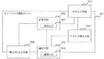
図7は、本実施の形態2に係るネットワーク開始サーバ701の構成を示すブロック図である。
ネットワーク開始サーバ701は、通信手段702、計算手段706、算出ID出力手段708、アドレス割当手段710を備える。
FIG. 7 is a block diagram showing a configuration of the
The
通信手段702は、有線又は無線のネットワーク接続インターフェースを備え、参加先のネットワークとの間で通信パケットの送受信を行う。また、通信パケットの送受信の際には、参加先ネットワークの識別ID703を併せて送受信する。その他、近隣ネットワークの通信パケットからそのネットワークの識別IDを検出して取り出す機能を持つ。
The
計算手段706は、通信手段702が近隣ネットワークの通信パケットからそのネットワークの識別IDを検出した際に、その識別IDの値から、所定の演算式を用いて算出ID707を計算する。
計算した算出IDは、算出ID出力手段708に出力される。
When the
The calculated calculation ID is output to the calculation ID output means 708.
算出ID出力手段708は、LED、7セグメントLEDや液晶ディスプレイなどの表示機を用いて構成することができる。これらの表示機を用いて、計算手段706により計算された算出IDをユーザーに提示する。
また、赤外線LEDを用いて構成しても良い。この場合は、ユーザーに算出IDの値を直接提示することができないため、ユーザーは赤外線LEDから出力される信号列をそのまま通信端末の受光部に照射させる。
The calculated ID output means 708 can be configured using a display device such as an LED, a 7-segment LED, or a liquid crystal display. Using these displays, the calculation ID calculated by the calculation means 706 is presented to the user.
Moreover, you may comprise using infrared LED. In this case, since the value of the calculated ID cannot be directly presented to the user, the user directly irradiates the light receiving unit of the communication terminal with the signal sequence output from the infrared LED.
ネットワークアドレス割り当て手段710は、新たにネットワークへの参入を要求してきた通信端末をネットワークに参入させ、ネットワークアドレスを割り当てる。通信端末との直接的な通信は通信手段702が行うため、ネットワークアドレス割り当て手段710自身は、割り当て済みアドレスの管理や、新規アドレスの生成などの、管理処理のみを行う。
The network address assignment means 710 causes a communication terminal that has newly requested entry into the network to enter the network and assigns a network address. Since the
次に、ネットワーク開始サーバ701のネットワーク開始動作を説明する。
Next, the network start operation of the
図8は、ネットワーク開始サーバ701がネットワーク開始を開始する際の動作フローである。以下、各ステップについて説明する。
FIG. 8 is an operation flow when the
(S801)
ネットワーク開始サーバ701が、ネットワーク開始手順を開始する。
(S802)
通信手段702は、近隣に存在するネットワークの識別IDを取得し、計算手段706に通知する。
(S803)
計算手段706は、通信手段702から受け取った識別ID毎に、通信端末と共通の所定の演算式を用いて算出IDを計算する。ここでは、実施の形態1の通信端末と同様に、ネットワークの識別IDを16で除算した剰余を算出IDとする。
本実施の形態2における「第2演算式」は、この16で除算した剰余を求める演算がこれに該当する。
(S804)
計算手段706は、ステップS803で計算したそれぞれの近隣ネットワークの指定IDを基に、使用されていない算出IDがあるか否かを判定する。
「使用されていない算出ID」とは、算出IDの桁数で表現できる数値の範囲内で、近隣ネットワークの算出IDとして使用されていない数値のことである。例えば、算出IDを4桁の2進数で表現するものとすると、0〜15の16個の数値の中で、近隣ネットワークの識別IDから求めた算出IDと重複しない算出IDを探すことになる。
使用されていない算出IDがあればステップS805へ進み、なければステップS806へ進む。
(S805)
計算手段706は、近隣ネットワークで使用されていない算出IDを元にして、算出IDを求める演算の逆演算によって識別IDの候補を算出し、候補の中からランダムに識別IDを選択する。
例えば、算出IDを算出する演算式が、識別IDを16で除算して剰余を求める演算であり、近隣ネットワークで使用されていない算出IDの値が「1」である場合には、識別IDの候補は「1」「17」「33」「49」・・・といった値が候補となる。この中から任意の識別IDをランダムに選択する。
(S806)
計算手段706は、ステップS802で取得したそれぞれの近隣ネットワークの識別IDを基に、使用されていない識別IDがあるか否かを判定する。
「使用されていない識別ID」とは、識別IDの桁数で表現できる数値の範囲内で、近隣ネットワークの識別IDとして使用されていない数値のことである。
使用されていない識別IDがあればステップS807へ進み、なければネットワーク開始処理を終了する。
(S807)
計算手段706は、近隣ネットワークが使用している算出IDの中で、最も重複の少ない算出IDを選び、ステップS805と同様の逆演算によって識別IDの候補を算出し、候補の中からすでに使用されている識別IDと一致しないものを選択する。
(S808)
計算手段706は、これまでのステップで決定した算出IDを、算出ID出力手段708に出力する。
算出ID出力手段708は、計算手段706より受け取った算出IDを表示する。
(S809)
ネットワーク開始サーバ701は、これまでのステップで決定した識別IDを用いて、ネットワークを開始する。
ここでの「ネットワークを開始する」とは、通信端末からのネットワーク参加リクエストを受け付け、参加を許可した通信端末に、ネットワークアドレスを割り当てることを言う。
(S801)
The
(S802)
The
(S803)
The
The “second arithmetic expression” in the second embodiment corresponds to an operation for obtaining a remainder obtained by dividing by 16.
(S804)
The
The “unused calculation ID” is a numerical value that is not used as a calculation ID of a neighboring network within a range of numerical values that can be expressed by the number of digits of the calculation ID. For example, if the calculated ID is expressed by a 4-digit binary number, a calculated ID that does not overlap with the calculated ID obtained from the identification ID of the neighboring network is searched for among 16 numerical values of 0 to 15.
If there is a calculation ID that is not used, the process proceeds to step S805, and if not, the process proceeds to step S806.
(S805)
The calculation means 706 calculates an identification ID candidate based on a calculation ID that is not used in the neighboring network by performing a reverse operation of the calculation for obtaining the calculation ID, and randomly selects an identification ID from the candidates.
For example, when the calculation expression for calculating the calculation ID is an operation for calculating the remainder by dividing the identification ID by 16, and the value of the calculation ID not used in the neighboring network is “1”, the identification ID The candidates are values such as “1”, “17”, “33”, “49”,. An arbitrary identification ID is randomly selected from these.
(S806)
The
The “unused identification ID” is a numerical value that is not used as an identification ID of a neighboring network within a range of numerical values that can be expressed by the number of digits of the identification ID.
If there is an identification ID that is not used, the process proceeds to step S807; otherwise, the network start process is terminated.
(S807)
The calculation means 706 selects the calculation ID with the least duplication from among the calculation IDs used by the neighboring network, calculates the identification ID candidate by the reverse operation similar to step S805, and is already used from among the candidates. The one that does not match the identified ID is selected.
(S808)
The
The calculation
(S809)
The
“Starting a network” here refers to accepting a network participation request from a communication terminal and assigning a network address to the communication terminal permitted to participate.
なお、算出ID出力手段708による算出IDの表示タイミングは、計算手段706より算出IDを受け取る毎に即座に表示することとしてもよいし、別途ボタンなどの入力手段を設けて、ユーザに表示タイミングを指定させてもよい。
また、算出ID出力手段708として赤外線LEDを用い、通信端末の入力手段204として赤外線ダイオードや赤外線トランジスタを用いても良い。この場合、ユーザは算出ID出力手段708を通信端末に向けることにより算出IDの送信を行う。
The display timing of the calculation ID by the calculation
Further, an infrared LED may be used as the calculation
以上のように、本実施の形態2に係るネットワーク開始サーバによれば、新規の識別IDを定義する場合に、自動的に算出IDの衝突を避けて定義するため、ネットワークに参入する通信端末に対して、算出IDを指定することによって参加するネットワークを指定することができる。
これにより、ユーザは非常にサイズの大きな識別IDに替えて、サイズの小さい指定IDだけを入力すればよく、識別IDを設定する手間が大幅に低減される。
As described above, according to the network start server according to the second embodiment, when a new identification ID is defined, it is automatically defined so as to avoid a collision of calculated IDs. On the other hand, the network to participate can be specified by specifying the calculation ID.
As a result, the user only has to input a designated ID having a small size in place of the identification ID having a very large size, and the labor for setting the identification ID is greatly reduced.
実施の形態3.
図9は、本発明の実施の形態3に係るネットワーク開始サーバ701の構成を示すブロック図である。
図9のネットワーク開始サーバ701は、図7の構成に加えて、新たに可否入力手段712を備える。その他の構成は図7と同様であるため、同様の符号を付して説明を省略する。
Embodiment 3 FIG.
FIG. 9 is a block diagram showing a configuration of the
The
可否入力手段712は、ユーザが以下の事項をネットワーク開始サーバ701に入力するために用いるものである。
(1)新規識別IDの割り当ての可否
新規の識別IDの生成を禁止したい場合に、ユーザがその旨を計算手段706へ伝えるために用いる。新規の識別IDの生成が禁止されると、ネットワーク開始サーバ701は新たなネットワークを開始することができず、既存のネットワークに参加することしかできなくなる。
こうした設定は、例えば管理者に無断でネットワークを開始することを運用上禁止する場合や、ネットワーク構成を不用意に変更したくない場合などに、有効な措置となる。
(2)ネットワークアドレスの新規割り当ての可否
ネットワークアドレスの新規発行を禁止したい場合に、ユーザがその旨をアドレス割当手段710へ伝えるために用いる。新規のアドレス割り当てが禁止されると、通信端末はそのネットワークに参加することができなくなる。
こうした設定は、例えばネットワークのトラフィックが溢れそうになっている場合に、新規の通信端末のネットワークへの参加を禁止する場合などに、有効な措置となる。また、通信端末の種別に応じて、参加可能なネットワークを制限する場合にも有効である。
The availability input means 712 is used by the user to input the following items to the
(1) Whether or not a new identification ID can be assigned When a user wants to prohibit the generation of a new identification ID, it is used by the user to notify the calculation means 706 of that fact. If the generation of a new identification ID is prohibited, the
Such a setting is an effective measure when, for example, it is operationally prohibited to start a network without the administrator's permission, or when it is not desired to change the network configuration carelessly.
(2) Whether or not a new network address can be assigned When a user wishes to prohibit a new issue of a network address, it is used by the user to notify the address assignment means 710 of that fact. When new address assignment is prohibited, the communication terminal cannot participate in the network.
Such a setting is an effective measure when, for example, network traffic is likely to overflow, and when new communication terminals are prohibited from participating in the network. It is also effective when restricting the networks that can participate according to the type of communication terminal.
可否入力手段712は、ネットワーク開始サーバ701の本体筐体に操作パネル等を設けることによって構成してもよいし、ネットワークインターフェースを介して遠隔から入力させるものでもよい。
さらには、ユーザに入力させるのみならず、ネットワーク開始サーバ701の製品出荷時点であらかじめROM等の記憶手段に格納済みとしてもよい。
The availability input means 712 may be configured by providing an operation panel or the like on the main body housing of the
Furthermore, not only the user may input, but the
以上のように、本実施の形態3に係るネットワーク開始サーバ701によれば、ユーザが新規識別IDやネットワークアドレスの割り当ての可否を入力する手段を設けたので、ネットワーク構成や運用上の制約等の条件をネットワーク開始サーバ701に反映させることができる。
As described above, according to the
なお、実施の形態2〜3で説明した構成のうち、通信手段702、計算手段706、算出ID出力手段708、及び可否入力手段712を切り出して、算出IDをユーザに提示するのみの機能を持つ機器を構成してもよい。この場合、切り出した機器は、算出ID出力器として、ネットワーク開始サーバとは別個に動作することとなる。
あるいは、既存のネットワーク開始サーバに、上述の算出ID出力器を組み込み、実施の形態2〜3で説明したような機能を追加することもできる。
Of the configurations described in the second to third embodiments, the
Alternatively, the above-described calculation ID output device can be incorporated into an existing network start server, and functions as described in the second to third embodiments can be added.
1 通信端末、100 家屋、101 ホームサーバ、200 家屋、201 ホームサーバ、210 通信端末、202 通信手段、203 識別ID、204 入力手段、205 指定ID、206 計算手段、207 算出ID、701 ネットワーク開始サーバ、702 通信手段、703 識別ID、706 計算手段、707 算出ID、708 算出ID出力手段、710 アドレス割当手段、712 可否入力手段。
1 communication terminal, 100 house, 101 home server, 200 house, 201 home server, 210 communication terminal, 202 communication means, 203 identification ID, 204 input means, 205 designation ID, 206 calculation means, 207 calculation ID, 701
Claims (11)
ネットワークとの間で通信パケットの送受信を行う通信手段と、
ネットワークの識別IDよりも桁数の少ない指定IDを入力する入力手段と、
ネットワークの識別IDに基づき、所定の第1演算式を用いて算出IDを計算する計算手段と、
を備え、
前記通信手段は、
近隣に存在する各ネットワークの識別IDを通信パケットから取得し、
前記計算手段は、
前記通信手段が取得した各ネットワークの識別ID毎に前記算出IDを計算し、
計算した算出IDと、前記入力手段へ入力された指定IDとが一致するネットワークに参加するように、前記通信手段に指示を出し、
前記通信手段が取得した各ネットワークの識別ID毎に前記算出IDを計算した際に、
計算した算出IDと、前記入力手段へ入力された指定IDとが一致するネットワークが複数存在する場合には、
それらのうちいずれかのネットワークに参加し、参加に失敗した際には、次のネットワークに参加するように、前記通信手段に指示を出す
ことを特徴とする通信端末。 A communication terminal that specifies an identification ID of a network to participate in and participates in the network,
A communication means for transmitting and receiving communication packets to and from the network;
An input means for inputting a designated ID having a smaller number of digits than the identification ID of the network;
Calculation means for calculating a calculated ID using a predetermined first arithmetic expression based on the identification ID of the network;
With
The communication means includes
Obtain the identification ID of each network in the neighborhood from the communication packet,
The calculating means includes
Calculating the calculated ID for each network identification ID acquired by the communication means;
Instruct the communication means to participate in a network in which the calculated ID calculated and the specified ID input to the input means match,
When calculating the calculated ID for each network identification ID acquired by the communication means,
When there are a plurality of networks in which the calculated ID and the specified ID input to the input means match,
Join any network of them, when it fails to participate, to participate in the next network, communication terminal you characterized in that instructs the communication unit.
ネットワークとの間で通信パケットの送受信を行う通信手段と、
ネットワークの識別IDよりも桁数の少ない指定IDを入力する入力手段と、
ネットワークの識別IDに基づき、所定の第1演算式を用いて算出IDを計算する計算手段と、
参加するネットワークの属性情報を指定する指定手段と、
を備え、
前記通信手段は、
近隣に存在する各ネットワークの識別IDを通信パケットから取得し、
前記計算手段は、
前記通信手段が取得した各ネットワークの識別ID毎に前記算出IDを計算し、
計算した算出IDと、前記入力手段へ入力された指定IDとが一致するネットワークに参加するように、前記通信手段に指示を出し、
前記通信手段が取得した各ネットワークの識別ID毎に前記算出IDを計算した際に、
計算した算出IDと、前記入力手段へ入力された指定IDとが一致するネットワークが複数存在する場合には、
それらのネットワークに順に参加してそのネットワークの属性情報を取得するように、前記通信手段に指示を出し、
前記通信手段は、
それらのネットワークに順に参加し、参加したネットワークの属性情報を取得して前記計算手段に出力し、
前記計算手段は、
前記指定手段により指定された属性情報と一致する属性を持つネットワークに参加するように、前記通信手段に指示を出す
ことを特徴とする通信端末。 A communication terminal that specifies an identification ID of a network to participate in and participates in the network,
A communication means for transmitting and receiving communication packets to and from the network;
An input means for inputting a designated ID having a smaller number of digits than the identification ID of the network;
Calculation means for calculating a calculated ID using a predetermined first arithmetic expression based on the identification ID of the network;
A specifying means for specifying attribute information of the network to join ;
With
The communication means includes
Obtain the identification ID of each network in the neighborhood from the communication packet,
The calculating means includes
Calculating the calculated ID for each network identification ID acquired by the communication means;
Instruct the communication means to participate in a network in which the calculated ID calculated and the specified ID input to the input means match,
When calculating the calculated ID for each network identification ID acquired by the communication means,
When there are a plurality of networks in which the calculated ID and the specified ID input to the input means match,
Instruct the communication means to participate in those networks in order and acquire the attribute information of the network,
The communication means includes
Participate in those networks in order, acquire attribute information of the participating networks and output to the calculation means,
The calculating means includes
Communication terminal you characterized in that to join the network, it instructs the communication means having attributes matching the specified attribute information by the specifying means.
ディップスイッチ又はロータリースイッチである
ことを特徴とする請求項1または請求項2に記載の通信端末。 The input means includes
Communication terminal according to claim 1 or claim 2 characterized in that it is a DIP switch or rotary switch.
ネットワークの識別IDに基づき、所定の第2演算式を用いて、ネットワークの識別IDよりも桁数の少ない算出IDを計算する計算手段と、
前記計算手段が計算した算出IDを出力する出力手段と、
を備え、
前記通信手段は、
近隣に存在する各ネットワークの識別IDを通信パケットから取得し、
前記計算手段は、
前記通信手段が取得した各ネットワークの識別ID毎に前記算出IDを計算し、
それらのネットワークと重複しない算出IDを求めて前記出力手段に出力し、
前記出力手段は、
前記計算手段より受け取った算出IDを出力する
ことを特徴とする算出ID出力器。 A communication means for transmitting and receiving communication packets to and from the network;
Calculation means for calculating a calculated ID having a smaller number of digits than the network identification ID using a predetermined second arithmetic expression based on the network identification ID;
Output means for outputting the calculated ID calculated by the calculating means;
With
The communication means includes
Obtain the identification ID of each network in the neighborhood from the communication packet,
The calculating means includes
Calculating the calculated ID for each network identification ID acquired by the communication means;
Find a calculation ID that does not overlap with those networks and output it to the output means;
The output means includes
A calculation ID output device that outputs the calculation ID received from the calculation means.
前記通信手段が取得した各ネットワークの識別ID毎に前記算出IDを計算した際に、
前記算出IDの桁数で表現可能な全ての値が、それらのネットワークの識別IDから計算した算出IDと重複している場合には、
それらいずれのネットワークの識別IDとも重複しない識別IDを求め、その識別IDを用いて、前記第2演算式により指定IDを算出して、前記出力手段に出力する
ことを特徴とする請求項4に記載の算出ID出力器。 The calculating means includes
When calculating the calculated ID for each network identification ID acquired by the communication means,
When all values that can be expressed by the number of digits of the calculated ID overlap with the calculated ID calculated from the identification ID of those networks,
They seek identification ID which does not overlap with the identification ID of any network, using the identification ID, and calculates the specified ID by the second operation expression, to claim 4, characterized in that the output to the output means The calculated ID output device described.
前記通信手段が取得した各ネットワークの識別ID毎に前記算出IDを計算した際に、
前記算出IDの桁数で表現可能な全ての値が、それらのネットワークの識別IDから計算した算出IDと重複している場合には、
重複の最も少ない前記算出IDを用いて、前記第2演算式の逆演算により、それらいずれのネットワークの識別IDとも重複しない識別IDを求め、
その識別IDを用いて、前記第2演算式により算出IDを計算して、前記出力手段に出力する
ことを特徴とする請求項4に記載の算出ID出力器。 The calculating means includes
When calculating the calculated ID for each network identification ID acquired by the communication means,
When all values that can be expressed by the number of digits of the calculated ID overlap with the calculated ID calculated from the identification ID of those networks,
By using the calculated ID with the least duplication, an identification ID that does not overlap with any of the network identification IDs is obtained by the inverse operation of the second arithmetic expression,
The calculated ID output device according to claim 4 , wherein the calculated ID is calculated by the second arithmetic expression using the identification ID, and is output to the output unit.
前記計算手段は、
前記新規識別ID可否入力手段より、識別IDの新規算出を禁止すべき旨の入力を受け取った際には、識別IDを新規算出しない
ことを特徴とする請求項4ないし請求項6のいずれかに記載の算出ID出力器。 A new identification ID availability input means for inputting whether or not a new identification ID can be calculated;
The calculating means includes
Than the new identification ID possibility input means, upon receiving the input to the effect that prohibits the new calculation of the ID is the one of claims 4 to 6, characterized in that no new calculated identification ID The calculated ID output device described.
請求項4ないし請求項7のいずれかに記載の算出ID出力器と、
前記算出ID出力器により、近隣に存在する各ネットワークの識別IDと重複しないものとして求められた識別IDを用いてネットワークを開始する手段と、
開始したネットワークに接続する通信端末にネットワークアドレスを割当てるアドレス割当手段と、
を備えたことを特徴とするネットワーク開始サーバ。 A server for starting a network identified by an identification ID,
A calculated ID output device according to any one of claims 4 to 7 ,
Means for starting a network using an identification ID determined by the calculated ID output unit as not overlapping with an identification ID of each network existing in the vicinity;
Address assignment means for assigning a network address to a communication terminal connected to the started network;
A network start server comprising:
前記アドレス割当手段は、
前記アドレス割当可否入力手段より、ネットワークアドレスの新規割当を禁止すべき旨の入力を受け取った際には、ネットワークアドレスの新規割当を行わない
ことを特徴とする請求項8に記載のネットワーク開始サーバ。 An address assignment availability input means for inputting the availability of new assignment of network addresses is provided,
The address assigning means includes
9. The network start server according to claim 8 , wherein when an input to prohibit new assignment of a network address is received from the address assignment enable / disable input unit, new assignment of a network address is not performed.
請求項8又は請求項9に記載のネットワーク開始サーバとを、
それぞれ1ないし複数有することを特徴とする通信ネットワークシステム。 A communication terminal according to any one of claims 1 to 3 ,
The network start server according to claim 8 or claim 9 ,
A communication network system comprising one or more of each.
Priority Applications (1)
| Application Number | Priority Date | Filing Date | Title |
|---|---|---|---|
| JP2007004236A JP4776552B2 (en) | 2007-01-12 | 2007-01-12 | Communication terminal, calculated ID output device, network start server, communication network system |
Applications Claiming Priority (1)
| Application Number | Priority Date | Filing Date | Title |
|---|---|---|---|
| JP2007004236A JP4776552B2 (en) | 2007-01-12 | 2007-01-12 | Communication terminal, calculated ID output device, network start server, communication network system |
Publications (2)
| Publication Number | Publication Date |
|---|---|
| JP2008172559A JP2008172559A (en) | 2008-07-24 |
| JP4776552B2 true JP4776552B2 (en) | 2011-09-21 |
Family
ID=39700227
Family Applications (1)
| Application Number | Title | Priority Date | Filing Date |
|---|---|---|---|
| JP2007004236A Expired - Fee Related JP4776552B2 (en) | 2007-01-12 | 2007-01-12 | Communication terminal, calculated ID output device, network start server, communication network system |
Country Status (1)
| Country | Link |
|---|---|
| JP (1) | JP4776552B2 (en) |
Families Citing this family (2)
| Publication number | Priority date | Publication date | Assignee | Title |
|---|---|---|---|---|
| JP5191828B2 (en) * | 2008-07-15 | 2013-05-08 | 富士電機株式会社 | Wireless communication network system, unregistered wireless terminal, registered wireless terminal, ID management wireless terminal, program |
| JP5159483B2 (en) * | 2008-07-15 | 2013-03-06 | 富士電機株式会社 | Wireless communication network system, ID management wireless terminal, unregistered wireless terminal, program |
Family Cites Families (2)
| Publication number | Priority date | Publication date | Assignee | Title |
|---|---|---|---|---|
| JP3997162B2 (en) * | 2003-01-28 | 2007-10-24 | キヤノン株式会社 | Network ID setting method |
| JP4033302B2 (en) * | 2004-05-07 | 2008-01-16 | 株式会社ソニー・コンピュータエンタテインメント | Wireless communication terminal device, wireless interface device, and wireless network participation method |
-
2007
- 2007-01-12 JP JP2007004236A patent/JP4776552B2/en not_active Expired - Fee Related
Also Published As
| Publication number | Publication date |
|---|---|
| JP2008172559A (en) | 2008-07-24 |
Similar Documents
| Publication | Publication Date | Title |
|---|---|---|
| US9749324B2 (en) | System, device and method for network authorization based on no password or random password | |
| CN111277474B (en) | Household appliance, network connection system of household appliance and network connection method of household appliance | |
| JP6263612B2 (en) | Communication event notification method, apparatus and system | |
| US20160037564A1 (en) | Network setup for limited user interface devices | |
| US9538375B2 (en) | Method for configuring wireless connection settings, wireless communications apparatus, and display method | |
| JP5880293B2 (en) | Communication system, call management server, location information server, and communication terminal | |
| TWI513351B (en) | Wireless network device and method for automatically configuring a wireless local area network connection | |
| JP6294814B2 (en) | Wireless communication method, wireless communication system, wireless communication apparatus, and program | |
| CN115996172A (en) | Equipment network distribution method and device | |
| JP4776552B2 (en) | Communication terminal, calculated ID output device, network start server, communication network system | |
| KR102310027B1 (en) | Determination method and corresponding terminal, computer program product and storage medium | |
| JP6270491B2 (en) | Authentication method and authentication system | |
| JP6133934B2 (en) | Remote controller | |
| JP6802354B2 (en) | Communication test equipment, communication test methods and programs | |
| JP4776568B2 (en) | Communication terminal, communication network system | |
| CN103780855B (en) | Information processing system and message processing device | |
| JP2005130307A (en) | Home network terminal and room gateway | |
| JP6101124B2 (en) | COMMUNICATION DEVICE, ITS CONTROL METHOD, PROGRAM | |
| EP3542598B1 (en) | Commissioning device for of one or more installed lighting devices | |
| JP2022171365A (en) | sensor device | |
| KR101676432B1 (en) | Discovery and Access System of Internet of Things board and Application Server under wireless WiFi Environment and method at the same | |
| KR20150107114A (en) | Smart Home Solution | |
| JP6294815B2 (en) | Wireless communication method, wireless communication system, wireless communication apparatus, and program | |
| JP2018182654A (en) | Communication device, communication control method and program | |
| KR101373099B1 (en) | Mobile information device and connection method to mobile router |
Legal Events
| Date | Code | Title | Description |
|---|---|---|---|
| A621 | Written request for application examination |
Free format text: JAPANESE INTERMEDIATE CODE: A621 Effective date: 20080718 |
|
| A977 | Report on retrieval |
Free format text: JAPANESE INTERMEDIATE CODE: A971007 Effective date: 20110121 |
|
| A131 | Notification of reasons for refusal |
Free format text: JAPANESE INTERMEDIATE CODE: A131 Effective date: 20110208 |
|
| A521 | Request for written amendment filed |
Free format text: JAPANESE INTERMEDIATE CODE: A523 Effective date: 20110407 |
|
| TRDD | Decision of grant or rejection written | ||
| A01 | Written decision to grant a patent or to grant a registration (utility model) |
Free format text: JAPANESE INTERMEDIATE CODE: A01 Effective date: 20110621 |
|
| A01 | Written decision to grant a patent or to grant a registration (utility model) |
Free format text: JAPANESE INTERMEDIATE CODE: A01 |
|
| A61 | First payment of annual fees (during grant procedure) |
Free format text: JAPANESE INTERMEDIATE CODE: A61 Effective date: 20110628 |
|
| R150 | Certificate of patent or registration of utility model |
Ref document number: 4776552 Country of ref document: JP Free format text: JAPANESE INTERMEDIATE CODE: R150 Free format text: JAPANESE INTERMEDIATE CODE: R150 |
|
| FPAY | Renewal fee payment (event date is renewal date of database) |
Free format text: PAYMENT UNTIL: 20140708 Year of fee payment: 3 |
|
| R250 | Receipt of annual fees |
Free format text: JAPANESE INTERMEDIATE CODE: R250 |
|
| R250 | Receipt of annual fees |
Free format text: JAPANESE INTERMEDIATE CODE: R250 |
|
| R250 | Receipt of annual fees |
Free format text: JAPANESE INTERMEDIATE CODE: R250 |
|
| R250 | Receipt of annual fees |
Free format text: JAPANESE INTERMEDIATE CODE: R250 |
|
| R250 | Receipt of annual fees |
Free format text: JAPANESE INTERMEDIATE CODE: R250 |
|
| R250 | Receipt of annual fees |
Free format text: JAPANESE INTERMEDIATE CODE: R250 |
|
| R250 | Receipt of annual fees |
Free format text: JAPANESE INTERMEDIATE CODE: R250 |
|
| R250 | Receipt of annual fees |
Free format text: JAPANESE INTERMEDIATE CODE: R250 |
|
| R250 | Receipt of annual fees |
Free format text: JAPANESE INTERMEDIATE CODE: R250 |
|
| LAPS | Cancellation because of no payment of annual fees |