JP4776545B2 - Contact ultrasonic transducer having a plurality of radiating elements and element contacting means - Google Patents
Contact ultrasonic transducer having a plurality of radiating elements and element contacting means Download PDFInfo
- Publication number
- JP4776545B2 JP4776545B2 JP2006540555A JP2006540555A JP4776545B2 JP 4776545 B2 JP4776545 B2 JP 4776545B2 JP 2006540555 A JP2006540555 A JP 2006540555A JP 2006540555 A JP2006540555 A JP 2006540555A JP 4776545 B2 JP4776545 B2 JP 4776545B2
- Authority
- JP
- Japan
- Prior art keywords
- transducer
- light
- radiating element
- rigid
- inspection object
- Prior art date
- Legal status (The legal status is an assumption and is not a legal conclusion. Google has not performed a legal analysis and makes no representation as to the accuracy of the status listed.)
- Expired - Fee Related
Links
- 238000007689 inspection Methods 0.000 claims description 32
- 239000000758 substrate Substances 0.000 claims description 15
- 238000012360 testing method Methods 0.000 claims description 13
- 239000013307 optical fiber Substances 0.000 claims description 12
- 238000002604 ultrasonography Methods 0.000 claims description 11
- 230000003287 optical effect Effects 0.000 claims description 10
- 238000012545 processing Methods 0.000 claims description 9
- 230000005284 excitation Effects 0.000 claims description 5
- 238000005259 measurement Methods 0.000 claims description 4
- 239000011159 matrix material Substances 0.000 description 8
- 230000008878 coupling Effects 0.000 description 6
- 238000010168 coupling process Methods 0.000 description 6
- 238000005859 coupling reaction Methods 0.000 description 6
- 239000000463 material Substances 0.000 description 5
- 239000011888 foil Substances 0.000 description 4
- 230000005855 radiation Effects 0.000 description 4
- 230000005355 Hall effect Effects 0.000 description 3
- 239000000835 fiber Substances 0.000 description 3
- 239000002184 metal Substances 0.000 description 3
- 238000000034 method Methods 0.000 description 3
- 238000010586 diagram Methods 0.000 description 2
- 238000005498 polishing Methods 0.000 description 2
- 229910000831 Steel Inorganic materials 0.000 description 1
- 230000003044 adaptive effect Effects 0.000 description 1
- 238000003491 array Methods 0.000 description 1
- 230000005540 biological transmission Effects 0.000 description 1
- 239000000470 constituent Substances 0.000 description 1
- 238000013461 design Methods 0.000 description 1
- 230000001066 destructive effect Effects 0.000 description 1
- 230000001788 irregular Effects 0.000 description 1
- 239000000696 magnetic material Substances 0.000 description 1
- 238000001465 metallisation Methods 0.000 description 1
- 229920000642 polymer Polymers 0.000 description 1
- 239000002952 polymeric resin Substances 0.000 description 1
- 230000001902 propagating effect Effects 0.000 description 1
- 229920005989 resin Polymers 0.000 description 1
- 239000011347 resin Substances 0.000 description 1
- 239000000523 sample Substances 0.000 description 1
- 239000010959 steel Substances 0.000 description 1
- 229920003002 synthetic resin Polymers 0.000 description 1
Images


Classifications
-
- G—PHYSICS
- G10—MUSICAL INSTRUMENTS; ACOUSTICS
- G10K—SOUND-PRODUCING DEVICES; METHODS OR DEVICES FOR PROTECTING AGAINST, OR FOR DAMPING, NOISE OR OTHER ACOUSTIC WAVES IN GENERAL; ACOUSTICS NOT OTHERWISE PROVIDED FOR
- G10K11/00—Methods or devices for transmitting, conducting or directing sound in general; Methods or devices for protecting against, or for damping, noise or other acoustic waves in general
- G10K11/18—Methods or devices for transmitting, conducting or directing sound
- G10K11/26—Sound-focusing or directing, e.g. scanning
- G10K11/34—Sound-focusing or directing, e.g. scanning using electrical steering of transducer arrays, e.g. beam steering
- G10K11/341—Circuits therefor
- G10K11/346—Circuits therefor using phase variation
Description
技術分野
本発明は、複数の放射エレメントを有する接触型超音波トランスデューサに関する。
本発明は、医療用、及び機械部材の非破壊検査に用いられ、特に、研磨又は材料の局所的追加等により生じる複雑な形状又は不規則な表面形状を有する部品に対して適用可能である。
TECHNICAL FIELD The present invention relates to a contact ultrasonic transducer having a plurality of radiating elements.
The present invention is used for medical and non-destructive inspection of mechanical members, and is particularly applicable to parts having complex shapes or irregular surface shapes caused by polishing or local addition of materials.
先行技術
一部の部品の超音波試験では、表面形状(幾何学的形状)が材料に応じて領域ごとに変化する材料の上に超音波トランスデューサが配置される。
このような場合、材料とトランスデューサの前面との音響結合は最適ではなく、伝播する超音波ビームの音響特性は維持されない。このような場合、検査品質は低下する。
Prior Art In ultrasonic testing of some parts, an ultrasonic transducer is placed on a material whose surface shape (geometric shape) varies from region to region depending on the material.
In such cases, the acoustic coupling between the material and the front face of the transducer is not optimal and the acoustic properties of the propagating ultrasonic beam are not maintained. In such a case, the inspection quality deteriorates.
従来技術では、形状が変化する部品を完全に検査することはできない。
例えば、配管分野においては、エルボ又は分岐等の形状変化は珍しくない。しかしながら、形状変化の大きい部品は、大きな機械的ストレスに耐えなければなないことが多く、従って頻繁な検査が必要となる。
In the prior art, a part whose shape changes cannot be inspected completely.
For example, in the piping field, shape changes such as elbows or branches are not uncommon. However, parts with large shape changes often have to withstand large mechanical stresses and therefore require frequent inspection.
このような領域に対する検査を最適化するため、不定形状の部品に適合する超音波トランスデューサが開発された。 In order to optimize inspection for such areas, ultrasonic transducers have been developed that fit indefinitely shaped parts.
第一のステップは、トランスデューサと部品表面との結合を最適化することであった。これを達成するため、モノリシックトランスデューサを、独立した基本トランスデューサの組み合わせに置き換えた。このセットは、部品の表面と接触すると変形できる。これにより、トランスデューサと検査対象物表面との接触性が改善された。
基本トランスデューサが、複数のエレメントを有する一つのアレーを形成しており、これらエレメントの異なる音響特性を定めることが必要であることに注意されたい。
The first step was to optimize the coupling between the transducer and the part surface. To achieve this, the monolithic transducer was replaced with a combination of independent basic transducers. This set can be deformed upon contact with the surface of the part. Thereby, the contact property between the transducer and the surface of the inspection object was improved.
Note that the basic transducer forms an array having a plurality of elements, and it is necessary to define the different acoustic characteristics of these elements.
次のステップでは、検査に必要な特性(屈折角及び部品内の焦点深度)を有する超音波を検査箇所に送る。次のステップでは、適切な電子手段を用いて、トランスデューサのエレメントに対し放射遅延を課し、よって必要な超音波ビームを形成する。
トランスデューサに装着された超音波センサから出力された電気信号は、その後統合される。これらの超音波センサは、基本超音波受信器として使用される上述のエレメントでもよい。
In the next step, an ultrasonic wave having the characteristics required for inspection (refraction angle and depth of focus in the part) is sent to the inspection site. In the next step, using appropriate electronic means, a radiation delay is imposed on the elements of the transducer, thus forming the required ultrasound beam.
The electrical signals output from the ultrasonic sensor attached to the transducer are then integrated. These ultrasonic sensors may be the elements described above that are used as basic ultrasonic receivers.
トランスデューサの電子制御手段に組込まれたシミュレーションソフトは、検査対象物の形状及び構成材料に依存する遅延時間、並びに超音波ビームに必要な特性を計算し、基本的なエミッタ励起信号を構築するために使用される。
また、部品表面の形状を把握しなければならない(先験的に不明)。これは、検査対象物の局所的な形状を決めるために使用できるデータを出力することができる手段を、トランスデューサ内に設けることによって行われる。これらのデータは、トランスデューサの制御手段にリアルタイムで入力され、対応する遅延規則を再計算する。この結果、「インテリジェント」と考えられる適応的トランスデューサが実現される。
The simulation software built into the transducer's electronic control means calculates the delay time depending on the shape and constituent materials of the object to be inspected, as well as the properties required for the ultrasound beam, and builds a basic emitter excitation signal. used.
In addition, it is necessary to grasp the shape of the part surface (a priori unknown). This is done by providing means in the transducer that can output data that can be used to determine the local shape of the test object. These data are input to the transducer control means in real time and the corresponding delay rules are recalculated. This results in an adaptive transducer that is considered “intelligent”.
このようなトランスデューサは、特許文献1に既知である。
また、フレキシブルな超音波トランスデューサは、特許文献2及び3に既知である。
Also, flexible ultrasonic transducers are known from Patent Documents 2 and 3.
発明の開示
本発明の目的は、このような不都合を解消することである。
この目的を達成するため、本発明は、複数のエレメントを備えた接触型超音波トランスデューサを提案する。本トランスデューサは、検査対象物の表面に前記エレメントを接触させる手段と、このエレメント接触手段を用いて、検査対象物に対するエレメントの位置を決める手段を備えること、及び各エレメントは少なくとも超音波エミッタであり、これら放射エレメントは剛性で、互いに機械的に組み立てられて関節構造を形成することを特徴とする。
DISCLOSURE OF THE INVENTION An object of the present invention is to eliminate such disadvantages.
In order to achieve this object, the present invention proposes a contact ultrasonic transducer having a plurality of elements. The transducer includes means for bringing the element into contact with the surface of the inspection object, means for determining the position of the element with respect to the inspection object using the element contact means, and each element is at least an ultrasonic emitter. The radiating elements are rigid and are mechanically assembled together to form a joint structure.
特許文献1〜3のいずれにおいても、このような手段の組み合わせは開示又は提案されていない。
特に、特許文献1に開示されたトランスデューサにおいては、トランスデューサが検査中に移動する際に、検査対象部とエレメントの接触を保ち、検査対象物との結合を確保する方法が何ら開示されていない。
None of Patent Documents 1 to 3 disclose or propose such a combination of means.
In particular, the transducer disclosed in Patent Document 1 does not disclose any method for maintaining the contact between the inspection object portion and the element and ensuring the coupling with the inspection object when the transducer moves during the inspection.
トランスデューサの複数のエレメントが剛性の放射エレメントであり、互いに機械的に組み立てられて関節構造を形成することにより、エミッタ間の結合が単純化及び改善され、1つのエミッタに隣接する別のエミッタが欠損した場合もこの結合が維持されるので、信頼性が向上する。
好適には、本トランスデューサは検査対象物に対し移動可能であり、エレメントの第一の表面によって形成された変形可能な放射面を有し、放射面は検査対象物の表面と接触し、放射面から検査対象物に超音波が放射され、放射エレメントの励起パルスを生成する制御手段が設けられ、トランスデューサの移動中に、検査対象物に対する超音波放射エレメントの位置が決定手段によって決定される。
Multiple elements of the transducer are rigid radiating elements that are mechanically assembled together to form an articulated structure, simplifying and improving the coupling between emitters, and missing another emitter adjacent to one emitter In this case, since this coupling is maintained, reliability is improved.
Preferably, the transducer is movable with respect to the test object and has a deformable radiating surface formed by the first surface of the element, the radiating surface being in contact with the surface of the test object, Ultrasonic waves are emitted from the object to be inspected, and control means for generating an excitation pulse of the radiation element is provided. During the movement of the transducer, the position of the ultrasonic radiation element with respect to the object to be examined is determined by the determining means.
処理手段が設けられ、この処理手段は、
− 上記のようにして求めた位置から、放射エレメントが集束超音波ビームを生成するために使用する、検査対象物に応じて特性が制御された遅延規則を決定し、且つ
− 前記遅延規則を励起パルスに適用する。
場合によっては放射エレメントから構成される超音波受信エレメントが設けられ、このエレメントは、検査対象物に関する画像を形成するために使用される信号を供給する。
前記接触手段は、検査対象物の表面に放射エレメントを接触させ、前記決定手段は、前記放射エレメントを接触させる手段を利用して、検査対象物に対する放射エレメントの位置を決定する。
Processing means is provided, the processing means comprising:
-Determining from the position determined as described above, a delay rule whose characteristics are controlled according to the object to be examined, used by the radiating element to generate a focused ultrasound beam; and-exciting the delay rule. Applies to pulses.
An ultrasound receiving element, optionally composed of a radiating element, is provided, which provides a signal that is used to form an image about the object to be examined.
The contact means brings the radiating element into contact with the surface of the inspection object, and the determining means determines the position of the radiating element with respect to the inspection object using the means for bringing the radiating element into contact.
本発明によるトランスデューサの好適な一実施形態によれば、検査対象物の表面に放射エレメントを接触させる手段は、それぞれがトランスデューサの剛性部分に対して自由に移動できる部分を含む複数の機械エレメントを備え、この可動部の第一端部は放射エレメントを検査対象物の表面に押し付けることができ、
検査対象物に対する放射エレメントの位置を決める手段は、
− 放射面の変形を測定する事によって、トランスデューサの剛性部分に対する放射エレメントの位置を決定し、このようにして求めた位置を表す信号を出力する第一の手段であって、
・各機械エレメントの可動部の第二端部とトランスデューサの剛性部分の領域との距離を測定する距離測定手段、及び
・このようして求めた距離を使用して、トランスデューサの剛性部分に対する放射エレメントの位置を決める補助処理手段
を備える第一の手段、
− 検査対象物に対する前記剛性部分の位置及び方向を決定し、このようにして求めた位置及び方向を表す信号を出力する第二の手段、並びに
− 第一の手段及び第二の手段によって出力された信号を使用して、検査対象物に対する放射エレメントの位置を出力する第三の手段
を備える。
好ましくは、各可動部の第一端部には丸みをつける。
According to a preferred embodiment of the transducer according to the invention, the means for bringing the radiating element into contact with the surface of the object to be tested comprises a plurality of mechanical elements, each including a part that is freely movable relative to the rigid part of the transducer. The first end of the movable part can press the radiating element against the surface of the inspection object,
The means for determining the position of the radiating element relative to the inspection object is:
-A first means for determining the position of the radiating element relative to the rigid part of the transducer by measuring the deformation of the radiating surface and outputting a signal representing the position thus determined,
A distance measuring means for measuring the distance between the second end of the movable part of each mechanical element and the region of the rigid part of the transducer, and using the distance thus determined, a radiating element for the rigid part of the transducer First means comprising auxiliary processing means for determining the position of
-A second means for determining the position and direction of the rigid part relative to the object to be inspected and outputting a signal representing the position and direction thus determined; and-outputted by the first means and the second means. A third means for outputting the position of the radiating element relative to the object to be inspected using the obtained signal.
Preferably, the first end of each movable part is rounded.
本発明の好適な一実施形態によれば、トランスデューサの剛性部分は、各可動部がそれぞれ自由に内部でスライドできる互いに平行な複数の穴を有し、各機械エレメントはまた、この機械エレメントに対応する可動部の第一端部を剛性部分の反対側に向かって加圧できる弾性手段を備える。
好適には、各機械エレメントは、対応する穴の内部に、各機械エレメントの可動部が低摩擦で自由にスライドすることを可能にする手段(例えば、ボールブッシング)を有する。
According to a preferred embodiment of the invention, the rigid part of the transducer has a plurality of parallel holes in which each movable part can slide freely inside, each machine element also corresponding to this machine element Elastic means that can pressurize the first end of the movable portion toward the opposite side of the rigid portion.
Preferably, each machine element has means (eg, a ball bushing) that allow the movable part of each machine element to slide freely with low friction within the corresponding hole.
本発明によるトランスデューサの好適な一実施形態によれば、各機械エレメントの可動部の第二端部と剛性部分の一領域との距離を光学的に測定する距離測定手段が設けられ、この手段は、
− 剛性部分に固定されて、光を反射できるこの第二端部に向かって光を放射する光放射手段、及び
− 剛性部分に固定されて、前述の反射光を受信し、前記第二端部とこれに対応する領域との間の距離を表す信号を出力することができる受光手段
を備える。
According to a preferred embodiment of the transducer according to the invention, a distance measuring means is provided for optically measuring the distance between the second end of the movable part of each mechanical element and a region of the rigid part, this means comprising: ,
A light emitting means for emitting light towards the second end, which is fixed to the rigid part and capable of reflecting light; and- a light emitting means fixed to the rigid part for receiving said reflected light and said second end And a light receiving means capable of outputting a signal representing a distance between the corresponding area and the corresponding area.
本発明によるトランスデューサの第一の特殊な実施形態においては、光放射手段と受光手段はそれぞれ、第二端部に対向する剛性部分に固定された、光電子エミッタ及び光検出器を含む。
本発明によるトランスデューサの第二の特殊な実施形態においては、光放射手段は、光を伝送し、第二端部に光を伝送する第一の光ファイバーを有し、受光手段は、第二端部によって反射された光を伝送する第二の光ファイバーを有含む。
In a first special embodiment of the transducer according to the invention, the light emitting means and the light receiving means each comprise a photoelectron emitter and a photodetector fixed to a rigid part opposite the second end.
In a second special embodiment of the transducer according to the invention, the light emitting means has a first optical fiber that transmits light and transmits light to the second end, and the light receiving means has a second end. A second optical fiber for transmitting the light reflected by the light source.
光学的距離測定手段は、連続的な光ビームを使用することができる。
一変形例として、光学的距離測定手段は、不連続な光ビーム、特に光波列を使用することもできる。
The optical distance measuring means can use a continuous light beam.
As a variant, the optical distance measuring means can also use a discontinuous light beam, in particular a light wave train.
本発明による特殊な一実施形態によれば、放射エレメントを接触させる手段はまた、放射エレメントの第二面を覆うブレードを含み、各機械エレメントの可動部の第一端部は、このブレードを介して放射エレメントを検査対象物の表面に押し付けることができ、このブレードにより、可動エレメントによって印加された圧力が放射エレメントに分散される。
別の特殊な実施形態においては、放射エレメントは、超音波に対し不活性なフレキシブルな基板に封入された剛性の圧電エレメントである。
According to a particular embodiment of the invention, the means for contacting the radiating element also includes a blade covering the second surface of the radiating element, the first end of the movable part of each mechanical element being interposed via this blade. The radiating element can then be pressed against the surface of the object to be examined, and this blade distributes the pressure applied by the movable element to the radiating element.
In another special embodiment, the radiating element is a rigid piezoelectric element encapsulated in a flexible substrate that is inert to ultrasound.
この場合、トランスデューサは、放射エレメントの数と同数のストリップを有することが好ましい。これらストリップは、機械エレメントと正対する位置にあるフレキシブルな基板の表面に固定される。各ストリップは、機械エレメントの内の1つの可動部に対向し、これらのストリップを介して、可動部の第一端部は、放射エレメントを検査対象物の表面に押付けることができる。
以降は、添付図面を参照し、本発明の例示的実施形態を説明する。これらの説明は、純粋に説明を目的としており、如何なる意味でも限定的なものではない。
In this case, the transducer preferably has as many strips as there are radiating elements. These strips are fixed to the surface of the flexible substrate in a position facing the mechanical element. Each strip faces one movable part of the mechanical elements, through which the first end of the movable part can press the radiating element against the surface of the object to be inspected.
Hereinafter, exemplary embodiments of the present invention will be described with reference to the accompanying drawings. These descriptions are purely illustrative and are not limiting in any way.
特定の実施形態の詳細な説明
図1を参照して説明する本発明の超音波トランスデューサは、フレキシブルトランスデューサであり、複雑な形状を有するために、全表面への到達が困難な小型部品の検査に適した手段を備えている。
このトランスデューサは、トランスデューサと検査対象物を接触状態にする手段と、形状測定手段(起伏センサ)とを備えている。
DETAILED DESCRIPTION OF SPECIFIC EMBODIMENTS The ultrasonic transducer of the present invention described with reference to FIG. 1 is a flexible transducer and has a complex shape, which makes it possible to inspect small parts that are difficult to reach all surfaces. Provide suitable means.
This transducer includes means for bringing the transducer into contact with the inspection object, and shape measuring means (undulation sensor).
接触状態にする手段は、検査対象物の走査に際し、本トランスデューサの放射エレメントと検査対象物の音響結合を確実に維持し、一方、個々の光学センサは、トランスデューサに装着されたスプリングピストンの位置を測定する。この測定結果は、検査対象部品の形状を論理的に推定するために使用され、この部分に適合する遅延規則を決定する。
トランスデューサ全体の大きさを出来るだけ小さくし、把持し易くするために、接触状態にする手段及び部品と接触する放射エレメント群の変形量を測定する手段は一体化される。これらの手段を一体化することにより、トランスデューサの限定された容積の中に、必要な数の光学センサ及び適合する電子手段を組み込むことができる。
The means for bringing into contact ensures that the acoustic coupling between the radiating element of the transducer and the test object is reliably maintained during the scan of the test object, while the individual optical sensors position the spring piston mounted on the transducer. taking measurement. This measurement result is used to logically estimate the shape of the part to be inspected to determine the delay rule that fits this part.
In order to reduce the overall size of the transducer as much as possible and facilitate gripping, the means for bringing into contact and the means for measuring the amount of deformation of the radiating element group in contact with the component are integrated. By integrating these means, the required number of optical sensors and compatible electronic means can be incorporated into the limited volume of the transducer.
図1は、特許文献1の第図4と互換性を有する。
図1の実施例では、直線状ストリップ形式のトランスデューサが使用されており、このトランスデューサは、超音波の入射面、即ち図1の(x、z)平面内の変形にのみ対応する。
FIG. 1 is compatible with FIG. 4 of Patent Document 1.
In the embodiment of FIG. 1, a linear strip type transducer is used, which corresponds only to deformations in the ultrasound incident surface, ie the (x, z) plane of FIG.
本トランスデューサは、弾性及び柔軟性を有する手段4を介して接続された超音波の送受信器エレメント2を備えており、これらのエレメントはフレキシブルなアセンブリを形成している。
エレメント2と、これらのエレメントから構成されるフレキシブルなアセンブリとの機械的な密着性を提供する手段4は、例えば、
− 2次元のフレキシブルトランスデューサの場合は、ケーブル、又は
− 3次元のフレキシブルトランスデューサの場合は、ポリマー樹脂の基板
とすることができる。
The transducer comprises an ultrasonic transceiver element 2 connected via elastic and flexible means 4 which form a flexible assembly.
Means 4 for providing mechanical adhesion between the element 2 and a flexible assembly composed of these elements includes, for example:
In the case of a two-dimensional flexible transducer, it can be a cable, or in the case of a three-dimensional flexible transducer, it can be a substrate of polymer resin.
一般的には、特許文献1に記載されているように、
− フレキシブルな圧電ポリマーのストリップ、及び金属析出法によって形成された互いに隣接して配置される電極アレー、
− 超音波に不活性なフレキシブル基板に埋め込まれた剛性の圧電エレメントの組、又は
− 関節構造を形成する機械的に組み立てられた剛性の超音波エレメントの組
を使用することも可能である。
図1に示す実施例においては、変形可能な既知の直線状多エレメントストリップが使用されており、このストリップに対し、圧電エレメント2は台形の形状を有している。
Generally, as described in Patent Document 1,
-Flexible piezoelectric polymer strips and electrode arrays arranged adjacent to each other formed by metal deposition;
It is also possible to use a set of rigid piezoelectric elements embedded in an ultrasonically inert flexible substrate, or a set of mechanically assembled rigid ultrasonic elements forming a joint structure.
In the embodiment shown in FIG. 1, a known deformable linear multi-element strip is used, for which the piezoelectric element 2 has a trapezoidal shape.
本トランスデューサは、スプリングピストン8及び金属性のホイル10を有し、このホイルはストリップ状のスプリングを構成し、圧電エレメント2と検査対象物6との接触を保持している。このストリップ状スプリングはエレメント2の組の背面上に位置し、このエレメントの各々は、前面、即ち、検査対象物6の表面と接触する活性面を有し、この活性面の組が変形可能な放射面を形成している。
金属ホイル10は、スプリングピストンによって印加された鉛直方向の力を分散し、ピストン8に妨げられることなく、エレメント2を水平方向に傾斜させることができる。
This transducer has a
The
また、図1に示すトランスデューサは剛性のボックス12を備えており、多エレメントストリップがこのボックスに固定されている。ボックス12は、同一平面に属する互いに平行な穴の組14を有しており、穴の数はスプリングピストンの数に等しい。
各スプリングピストン8は、対応する穴の中でスライドできる可動部16と、スプリング18とを有し、可動部16はスプリング内を通過し、スプリングは、ボックス12と、エレメント2に近い方の可動部の端部20との間に挿入されている。
The transducer shown in FIG. 1 also includes a
Each
端部20の幅は、可動部の他の部分よりも広く、これによってスプリング18の脱落が防止される。金属ホイル10を介してエレメント2の裏面に印加される圧力を最適化するため、端部20は丸みを帯びた形状で、好ましくは図1に示すような半球状である。
トランスデューサを検査対象物6に接触させると、スプリング18は圧縮されてボックス12の端部20をボックスとは反対側へ向かって加圧するので、エレメント2は検査対象物6と接触された状態に維持される。
The width of the
When the transducer is brought into contact with the test object 6, the
各穴14の内部には穴と同軸のボールブッシング22が設けられ、穴の内部で、この穴に対応するピストンの可動部16が自由にスライドできる。ボールブッシング22は、穴内部での可動部の移動性を向上させて、移動時の摩擦を減らし、可動部と穴の間の隙間を排除するために設けられている。
トランスデューサが移動する際の、検査対象物6に対するエレメント2の位置は、スプリングピストンにより求められる。
A ball bushing 22 coaxial with the hole is provided inside each
The position of the element 2 relative to the inspection object 6 when the transducer moves is determined by a spring piston.
このために、ボックス12の上部には(剛性の)プレート24が設けられており、このプレートは、穴14の上端部を封鎖し、エレメント2の位置を測定するための形状基準面を構成する。各穴14の中には、プレート24の領域29に対応する位置に、発光ダイオード26及び光検出器28が取り付けられている。領域29は、この穴に対応するピストンの可動部16の、他方の端部30と正対している。
この他端部30は、穴14と可動部16に共通なX軸と垂直であり、他端部は研磨されているか、又は研磨等による反射体に作製され、ミラーを形成している。このミラーは発光ダイオード26から放射された光ビームの一部を反射する。反射光のエネルギーの量は、可動部と発光ダイオード26の間の距離に反比例する。
For this purpose, a (rigid)
The
ミラーによって反射された光ビームは、ダイオード26に隣接して設置される光検出器28によって捕獲される。次いで、この光検出器は、可動部16の他端部30と光検出器(つまりプレート24)の間の距離に応じた光電流、即ち剛性部品12に対するエレメント2の位置を出力する(可動部16の長さは既知である)。
プログラム可能な電子手段32が設けられ、発光ダイオード26の制御、各光検出器28から出力された光電流の符号化、及び光電流の移動距離への変換を行う。
The light beam reflected by the mirror is captured by a
Programmable electronic means 32 are provided to control the
しかしながら、光電流の関数である移動距離の変異曲線は線形でないので、較正が必要である。
この較正作業は、各ピストン8の可動部16の複数の較正位置における光電流を測定する取得段階において実施され、前記較正位置は、このピストンの範囲全体、即ちこのピストンが移動可能な全域に亘る。
However, the variation curve of travel distance, which is a function of photocurrent, is not linear and requires calibration.
This calibration operation is carried out in an acquisition phase in which photocurrents are measured at a plurality of calibration positions of the
各光検知器の較正の終了後、測定された光電流を移動距離へ変換することができる。
エレメント2の背面に対する各光検知器の位置は既知であるので、エレメントの背面によって表現される形状を、内挿補間法を用いて再構築することができる。次いで、投影作業により検査対象物6の表面の座標値が得られる。
After the calibration of each photodetector, the measured photocurrent can be converted to a travel distance.
Since the position of each photodetector relative to the back surface of element 2 is known, the shape represented by the back surface of the element can be reconstructed using interpolation. Next, the coordinate value of the surface of the inspection object 6 is obtained by the projection operation.
具体的には、手段32はまた、剛性のボックス12に対するエレメント2の背面位置を決定するように設計されている。
補助処理手段34は、このようにして求めた背面位置の関数として、ボックスに対するエレメント2の活性面の位置を決定する(特許文献1参照)。
In particular, the
The auxiliary processing means 34 determines the position of the active surface of the element 2 with respect to the box as a function of the back surface position thus determined (see Patent Document 1).
トランスデューサの位置と方向を、検査対象物6の固定座標系において得るため、関節式の機械アーム36が使用される。参照特許文献1に示されているように、関節式アーム36に取り付けられたセンサ38を使用して、空間内におけるトランスデューサの位置を決定し、検査対象物6に対してトランスデューサが移動する間の、その方向を計測する。
図1はまた、手段34から出力された位置に基づき、且つセンサ38から出力された位置及び方向の関数として、検査対象物6に対するトランスデューサの位置を決定する手段40を示す。
In order to obtain the position and orientation of the transducer in the fixed coordinate system of the inspection object 6, an articulated
FIG. 1 also shows a
図1には更に、制御及び処理手段42が示されており、この手段42は、
− エレメント2の励起パルスを生成し、
− 前述のようにして求めた位置を使用して遅延規則を決定し、検査対象物6に関して制御される集束超音波ビームFをエレメント2が生成できるようにし、且つ
−これらの遅延規則を励起パルスに適用する。
次いで、エレメント2は手段42に信号を送り、手段42はまたこれらの信号を使用して検査対象物6の画像を形成する。
これらの画像は、スクリーン44上に描画される。
Also shown in FIG. 1 is control and processing means 42, which means 42 includes:
-Generating an excitation pulse of element 2;
Using the positions determined as described above to determine the delay rules so that the element 2 can produce a focused ultrasound beam F that is controlled with respect to the object 6 to be examined; and Applies to
The element 2 then sends a signal to the
These images are drawn on the
特許文献1に記載されているように、慣性センサを使用して、トランスデューサの位置と方向を得ることもできる。
発光ダイオードを制御して、連続光ビーム又は不連続光ビーム、特に光パルスを放射することができる。
対応する発光ダイオードを制御することにより、必要とする光検出器28を検索するように、プログラマブルな電子手段32を設計することも可能である。
As described in Patent Document 1, an inertial sensor can be used to obtain the position and orientation of the transducer.
The light emitting diode can be controlled to emit a continuous light beam or a discontinuous light beam, in particular a light pulse.
It is also possible to design the programmable electronic means 32 to search for the required
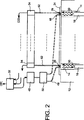
図1に示すトランスデューサの一変形例の部分概略図を図2に示す。本変形例では、光ファイバーを使用して、対応するピストンの可動部の第二端に光を伝送し、これら第二端で反射された光を伝送する。
図2の実施例では、手段32が、光学カプラー50を介して光ファイバー48の端部に光を伝送する光源46を制御しており、ファイバーの数はピストンの数に等しい。図2に示すように、光ファイバー48の他方の端部は穴14内に開いており、可動部16の反射端30を「照射」することができる。
FIG. 2 shows a partial schematic diagram of a variation of the transducer shown in FIG. In this modified example, an optical fiber is used to transmit light to the second end of the movable part of the corresponding piston, and transmit light reflected by these second ends.
In the embodiment of FIG. 2, the
光ファイバー毎に1つの光源を使用することもできる。
光ファイバーの他端のそれぞれは、プレート24の領域29に固定されており、これらの領域は対応する端部30に正対している。
One light source can be used for each optical fiber.
Each of the other ends of the optical fiber is fixed in a
更に、ファイバー48と同数の別の光ファイバー52が設けられており、その端部は、光ファイバー48の端部と隣接して穴14内に開いており、対応する反射端30に正対する領域29に固定されている。
ファイバー52は、可動部16の反射端30によって反射された光を回収し、この光を対応する光検出器54に伝送する。次いで、これらの光検出器は光電流を生成し、これを手段32に送る。
Further, the same number of other
The
上述した本発明の実施例においては、特にピストンの移動量を検出するために使用される距離測定手段が光学的手段から構成されているので、ピストンの移動を光学的に測定することが可能である。
しかしながら、これらの光学的手段を電磁手段で置換することも可能である。
In the above-described embodiment of the present invention, the distance measuring means used for detecting the movement amount of the piston is composed of optical means, so that the movement of the piston can be measured optically. is there.
However, it is also possible to replace these optical means with electromagnetic means.
図示しない一実施例では、図1に示す発光ダイオード26と光検出器28の組は、ホール効果センサで置換することが可能であり、対応するピストンの可動部の端部30に磁石が取付けられる。
この方式において、ホール効果センサは、このセンサと磁石との間の距離に基づく信号を出力することができる。従って、図1に示す手段32を、このセンサを制御し、このセンサから出力される信号を処理する適切な手段で置き換えることにより、必要とされる距離を測定することができる。
In one embodiment (not shown), the pair of
In this system, the Hall effect sensor can output a signal based on the distance between the sensor and the magnet. Accordingly, the required distance can be measured by replacing the
この実施例の一変形例(図示せず)では、対応する穴14内において、プレートの、ホール効果センサに隣接する位置に磁石を固定し、各ピストンの可動部の少なくとも端部30は鋼等の磁性材で作る。
このとき、各センサによって検知される磁界は対応する端部30によって妨害され、センサはまた、この端部30とセンサとの間の距離に基づく信号を出力する。
In a modified example (not shown) of this embodiment, a magnet is fixed in the corresponding
At this time, the magnetic field detected by each sensor is disturbed by the
更に、上述した本発明の実施例において、超音波送受信エレメントを使用する。当業者であれば、これらの実施例を、送信専用の超音波エレメント及び受信専用の超音波エレメントを含むトランスデューサに適用することができる。
更に、これらの実施例においては、直線状のストリップ形式の超音波エレメントを有するトランスデューサが使用されているが、本発明はこのようなトランスデューサに限定されるものではない。特許文献1に記載されているように、当業者であれば、これらの実施例をマトリックス型トランスデューサに適用することができる。
Furthermore, in the above-described embodiment of the present invention, an ultrasonic transmission / reception element is used. Those skilled in the art can apply these embodiments to transducers that include a transmit-only ultrasound element and a receive-only ultrasound element.
Further, in these embodiments, a transducer having a linear strip type ultrasonic element is used, but the present invention is not limited to such a transducer. As described in Patent Document 1, those skilled in the art can apply these embodiments to a matrix transducer.
この場合、平行なスプリングピストンの列と、マトリックス型トランスデューサとを関連付けることが必要となる。上述のようなスプリングピストンの列は、図1に示した種類のものであり、トランスデューサに取付けられたエレメントの背面上の金属性ホイルを含む。
次に、図3を参照して本発明の別の実施例を説明する。本実施例は、特に超音波エレメントが1列ではなくマトリックスを形成する場合に有用である。
In this case, it is necessary to associate matrix spring transducers with parallel rows of spring pistons. The row of spring pistons as described above is of the type shown in FIG. 1 and includes a metallic foil on the back of the element attached to the transducer.
Next, another embodiment of the present invention will be described with reference to FIG. This embodiment is particularly useful when the ultrasonic elements form a matrix rather than a single row.
図3の断面図に示すように、本発明によるトランスデューサは、フレキシブルな樹脂基板58の内部に埋め込まれた、マトリックス状の超音波送受信エレメント56を備え、この基板は超音波に対して不活性である。
圧電エレメント56を、図3の実施例において凸状に示す検査対象物と接触させた状態で維持するため、本トランスデューサは、スプリングピストンから構成されるマトリックスアセンブリ62及び剛性のボックス64を備えている。ボックス64には、フレキシブル基板58が後述する方法で固定される。
As shown in the cross-sectional view of FIG. 3, the transducer according to the present invention includes a matrix-like ultrasonic transmitting / receiving element 56 embedded in a
In order to maintain the piezoelectric element 56 in contact with the test object shown convex in the embodiment of FIG. 3, the transducer comprises a
ボックス64は、互いに平行に配置された穴66から構成されるマトリックスアセンブリを有し、各穴はそれぞれ、スプリングピストンと対応する。各スプリングピストンは、対応する穴の内部でスライド可能な可動部68、及びスプリング70を有し、可動部16はスプリングの内部を通って移動し、スプリングはボックス64とエレメント56に近い方の可動部の端部72との間に挿入されている。この端部72は丸みを帯びた形状であり、好ましくは図1に示すような半球状である。
図3に示すように、この実施例においてもボールブッシング74が設けられ、よって対応する穴68の内部における可動部68の移動性が向上している。
As shown in FIG. 3, the ball bushing 74 is also provided in this embodiment, thereby improving the mobility of the movable portion 68 inside the corresponding hole 68.
図3の実施例において、検査対象物60に対するエレメント56の位置は、トランスデューサが移動する間に、スプリングピストンによって測定される。このために、各ピストンは、図1の実施例に示すように位置センサ76に接続される。
図3に示す実施例においても、ピストンに向かって光を放射する光放射器と、このピストンの可動部68の後端部によって反射された光を受信する受光器とを有する光学センサが使用されている。尚、ピストン可動部の後端部は、この目的のために反射機能を有するように作られている。
In the embodiment of FIG. 3, the position of the element 56 relative to the
In the embodiment shown in FIG. 3 as well, an optical sensor having a light emitter that emits light toward the piston and a light receiver that receives the light reflected by the rear end portion of the movable portion 68 of the piston is used. ing. The rear end portion of the piston movable portion is made to have a reflection function for this purpose.
好適には、フレキシブル基板58の上部表面にストリップ78が取付けられて、ピストンの半球状端部72に対向し、よってマトリックスアセンブリを形成する。これらストリップは、スプリングピストンによって印加される圧力を分散するために使用される。これらストリップは、半球状端部の直径と等しい直径を有する薄い金属性の円盤を形成することが好ましい。
図3に示すトランスデューサは更に、例えば、互いに90度の角度を形成する4つの支持部80を備える。図3では、これら支持部の2つだけを見ることができる。各支持部は、支持部に関節結合されているロッド82を介してフレキシブル基板58に取り付けられている。ロッド82は、樹脂製のフレキシブル基板の内部に埋め込まれたインサート84の内部でスライド可能である。
Preferably, a
The transducer shown in FIG. 3 further includes, for example, four
各支持部80はまた、軸86の一方の端部に固定されている。軸86の他方の端部は、図3に示すように、剛性のボックスを貫通する穴88の内部でスライド可能である。穴88は、ピストン可動部がその内部でスライドする穴66と平行である。
インサート84の内部でスライド可能なロッド82を使用することにより、基板58を断裂させる恐れのある横方向の張力の発生を抑えることができる。
Each
By using the
更に、支持部80、ロッド82、インサート84、及び軸86を有する本機械システムは、フレキシブル基板58の回転を抑えることが可能であり、従ってエレメント56の組の回転も抑止できる。
必要に応じて、ボックス64に対するフレキシブルな基板58の移動を、検知器76のような位置検出器90を用いて測定することができ、位置検出器90は、フレキシブル基板を保持するために使用される軸86の移動距離の測定に使用できる。
Further, the present mechanical system having the
If desired, movement of the
図3はまた、ロッド82が貫通するスプリング91を示し、このスプリングは、支持部80と剛性のボックス64との間に挿入されている。
これらロッド82の各々はまた、ボールブッシング94を介して剛性のボックス64の内部でスライド可能な、支持部80に固定された別のロッド92に接続できる。図3に示すように、この場合、この支持部80と剛性ボックス64間にはスプリング96が設けられ、この中をロッド92が通過する。
FIG. 3 also shows a
Each of these
剛性のボックス64は、トランスデューサのハンドルとしても使用できる電子ボックス98に取付けることができる。この電子ボックス98の上部に示すエレメント100を通して電気ケーブル類(図示せず)が配置される。これらのケーブルは、トランスデューサ及び位置センサ76から出力された信号を伝送するために使用される。
電気ボックス98の底部には基盤102を設け、個々の超音波エレメント56から引き出された電気コネクタ(図示せず)を保持し、これらのコネクタを電子ボックス98内の、エレメント56を制御し、エレメントから出力された信号を処理するために使用される電子手段に接続することができる。
ボールブッシング94とスプリング96を伴うロッド92は、支持部80に固定された、剛性のボックス64内にこのために設けられた穴の中でスライド可能な簡単なアングルに置き換えることができる。
The
A
The
図面の簡素化のため、図3に示すトランスデューサに必要な種々の電気的接続は図示しない。
同様に、本トランスデューサの動作に必要な種々の信号制御手段及び処理手段を図示しない。マトリックス型トランスデューサに対応するこれらの手段は、当業者であれば、図1で説明した線形トランスデューサの手段に類似のものを用いることにより、決定することができる。
To simplify the drawing, the various electrical connections required for the transducer shown in FIG. 3 are not shown.
Similarly, various signal control means and processing means necessary for the operation of the transducer are not shown. Those means corresponding to the matrix type transducer can be determined by those skilled in the art by using something similar to that of the linear transducer described in FIG.
Claims (12)
前記放射エレメント(2)の第二の面を覆うブレード(10)を備え、
前記剛性部分(12)に対して自由に移動できる可動部(16)と前記可動部(16)に作用する弾性手段(18)とを有した複数の機械エレメント(8)を備え、
前記可動部(16)は前記ブレード(10)を介して前記放射エレメント(2)を前記検査対象物(6)の表面に押し付けることができる第一端部(20)を含み、
前記弾性手段(18)は前記可動部(16)の前記第一端部(20)を前記剛性部分(12)から遠ざけることができ、
前記機械エレメント(8)を用いて前記検査対象物(6)に対する前記各放射エレメント(2)の位置を測定する手段(26、28、34、36、38、40、48、52)を備え、
前記各放射エレメント(2)が少なくとも超音波の放射体であり、
前記各放射エレメント(2)が剛体であること
を特徴とする、トランスデューサ。 A plurality of radiating elements (2) having a first surface for contacting the surface of an inspection object (6), and a joint structure formed by mechanically assembling the radiating elements (2). A contact-type ultrasonic transducer having a rigid part (12) to be fixed ,
A blade (10) covering the second surface of the radiating element (2);
A plurality of mechanical elements (8) having a movable part (16) freely movable relative to the rigid part (12) and elastic means (18) acting on the movable part (16);
The movable part (16) includes a first end (20) capable of pressing the radiating element (2) against the surface of the inspection object (6) via the blade (10),
The elastic means (18) can move the first end (20) of the movable part (16) away from the rigid part (12),
The equipped with a mechanical element the inspection object using (8) means for measuring the position of each radiating element (2) with respect to (6) (26,28,34,36,38,40,48,52),
Each radiating element (2) is at least an ultrasonic radiator;
Transducer, characterized in that each radiating element (2) is rigid.
前記放射エレメント(2)の前記第一の面によって形成された変形可能な放射面を有し、
前記放射面は前記検査対象物(6)の前記表面と接触して前記検査対象物(6)に超音波を放射し、
前記放射エレメント(2)の励起パルスを生成する制御手段(42)を備え、
前記放射エレメント(2)の前記位置測定手段(26、28、34、36、38、40、48、52)はトランスデューサが移動する間に前記検査対象物(6)に対する前記放射エレメント(2)の位置を測定し、
− 前記測定した位置から、前記検査対象物(6)に応じて特性が制御された集束超音波ビーム(F)を生成するために、前記放射エレメント(2)によって使用される遅延規則を決定し、
且つ
− 該遅延規則を励起パルスに適用する
処理手段を備え、
前記放射エレメント(2)から構成することもできる超音波受信エレメントが、前記検査対象物(6)の影像を構築するために使用される信号を供給する、請求項1に記載のトランスデューサ。 Movable with respect to the inspection object (6),
Wherein a said first deformable emitting surface formed by the surface of the radiating element (2),
The radiating surface radiates an ultrasonic wave to the inspection object (6) in contact with the surface of the inspection object (6),
Wherein a control means for generating an excitation pulse radiating element (2) (42),
Said radiating elements wherein relative to the position measuring means radiating element (2) (26,28,34,36,38,40,48,52) the inspection object while the transducer is moved (6) (2) Measure the position,
- from a position the measurement, in order to generate the test object focusing properties are controlled in accordance with (6) the ultrasound beam (F), and determines the delay rule the used by the radiating element (2) ,
And - comprising a processing means for applying the delay rule to the excitation pulse,
Ultrasonic receiving element may also be configured from the radiating element (2) is providing a signal used to build a shadow image of the inspection object (6) The transducer of claim 1.
− 前記放射面の変形を測定する事によって、前記剛性部分(12)に対する前記放射エレメント(2)の位置を求め、且つ当該求めた位置を表す信号を出力する第一の手段であって、
・ 前記各機械エレメント(8)の前記可動部(16)の第二端部(30)と前記剛性部分(12)の一領域(29)との間の距離を測定する距離測定手段(26、28、48、52)、及び
・ 該測定した距離を使用して、前記剛性部分(12)に対する前記放射エレメント(2)の位置を求める補助処理手段(34)
を備える第一の手段(26、28、34、48、52)と、
− 前記検査対象物(6)に対する前記剛性部分(12)の位置及び方向を求め、該求めた位置及び方向を表す信号を出力する第二の手段(36、38)、並びに
− 前記第一の手段(26、28、34、48、52)及び前記第二の手段(36、38)から出力された信号を使用して、前記検査対象物(6)に対する前記放射エレメント(2)の位置を出力する第三の手段(40)
を備える、請求項2に記載のトランスデューサ。 Wherein the position measuring means (26,28,34,36,38,40,48,52) are of the radiating element relative to the inspection object (6) (2),
- by measuring the deformation of the emitting surface, said determined position of the radiating element (2), a first means for outputting a signal and representing the obtained position relative to the rigid portion (12),
- said distance measuring means (26 for measuring the distance between the second end of the movable portion (16) and (30) and a region (29) of said rigid portion (12) of each machine element (8), 28,48,52), and using the distances, the measurement, the auxiliary processing means for determining the position of the radiating element relative to said rigid portion (12) (2) (34)
First means (26, 28, 34, 48, 52) comprising:
- determine the position and orientation of the rigid portion relative to the test object (6) (12), second means for outputting a signal representative of the position and direction obtained the (36, 38), and - the first means (26,28,34,48,52) and by using the signal output from said second means (36, 38), the position of the radiating element (2) with respect to the inspection object (6) Third means for output (40)
The transducer according to claim 2, comprising:
− 前記剛性部分(12)に固定され、放射光を反射することができる前記第二端部(30)に向かって光を放射する光放射手段(26、48)、及び
− 前記剛性部分(12)に固定され、反射された光を受信する受光手段(28、52)
を備え、前記受光手段(28、52)は、前記第二端部(30)とこれに対応する前記領域(29)間の距離を表す信号を出力することができる、請求項3ないし6のいずれか一項に記載のトランスデューサ。 Said distance measuring means (26,28,48,52), the said one region of the second end portion (30) and said rigid portion of said movable portion of the machine element (8) (16) (12) ( 29) is provided to optically measure the distance between
- fixed to said rigid portion (12), light emission means for emitting light toward the second end portion capable of reflecting the emitted light (30) (26, 48), and - the rigid portion (12 ) to be fixed, the light receiving means for receiving the reflected light (28,52)
Wherein the light receiving means (28,52) is capable of outputting a signal representative of the distance between the region (29) corresponding thereto and said second end portion (30), of claims 3 to 6 The transducer according to any one of the above.
前記ブレードが放射エレメントの数と同数のストリップ(78)であり、
前記ストリップ(78)が前記機械エレメントに正対して位置する前記フレキシブルな基板(58)の表面に固定されている、請求項1ないし11のいずれか一項に記載のトランスデューサ。 The radiating element is a rigid piezoelectric element (56) enclosed in a flexible substrate (58) inert to ultrasound;
The blade is the same number of strips (78) as the number of radiating elements;
The strip (78) is fixed to the surface of the flexible substrate (58) located directly opposite to the machine element, transducer according to any one of claims 1 to 11.
Applications Claiming Priority (3)
| Application Number | Priority Date | Filing Date | Title |
|---|---|---|---|
| FR0350842 | 2003-11-17 | ||
| FR0350842A FR2862385B1 (en) | 2003-11-17 | 2003-11-17 | ULTRASONIC CONTACT TRANSDUCER WITH MULTIPLE TRANSMITTING ELEMENTS AND MEANS FOR PLATING THESE ELEMENTS |
| PCT/FR2004/050589 WO2005050617A2 (en) | 2003-11-17 | 2004-11-16 | Ultrasonic contact transducer comprising multiple emitting elements and means for pressing said elements |
Publications (2)
| Publication Number | Publication Date |
|---|---|
| JP2007511970A JP2007511970A (en) | 2007-05-10 |
| JP4776545B2 true JP4776545B2 (en) | 2011-09-21 |
Family
ID=34508764
Family Applications (1)
| Application Number | Title | Priority Date | Filing Date |
|---|---|---|---|
| JP2006540555A Expired - Fee Related JP4776545B2 (en) | 2003-11-17 | 2004-11-16 | Contact ultrasonic transducer having a plurality of radiating elements and element contacting means |
Country Status (6)
| Country | Link |
|---|---|
| US (1) | US7955266B2 (en) |
| EP (1) | EP1687804B1 (en) |
| JP (1) | JP4776545B2 (en) |
| CA (1) | CA2546176C (en) |
| FR (1) | FR2862385B1 (en) |
| WO (1) | WO2005050617A2 (en) |
Families Citing this family (12)
| Publication number | Priority date | Publication date | Assignee | Title |
|---|---|---|---|---|
| JP4770386B2 (en) * | 2005-10-21 | 2011-09-14 | 株式会社日立製作所 | Ultrasonic probe of ultrasonic flaw detector |
| FR2930642B1 (en) * | 2008-04-23 | 2010-06-11 | Commissariat Energie Atomique | ULTRASOUND CONTACT TRANSLATOR WITH MULTIPLE ELEMENTS, FLEXIBLE SHEET AND PROFILOMETER |
| KR101107154B1 (en) * | 2009-09-03 | 2012-01-31 | 한국표준과학연구원 | Multi probe unit for ultrasonic flaw detection apparatus |
| FR2965923B1 (en) * | 2010-10-11 | 2012-12-14 | Commissariat Energie Atomique | ULTRASONIC SURVEY DEVICE, METHOD FOR CONTROLLING TRANSDUCERS OF ULTRASONIC PROBE AND CORRESPONDING COMPUTER PROGRAM |
| DE102012101579A1 (en) * | 2012-02-27 | 2013-08-29 | Ge Sensing & Inspection Technologies Gmbh | Wear sole for connection to an ultrasonic probe |
| FR2988173B1 (en) | 2012-03-15 | 2014-04-11 | Commissariat Energie Atomique | MULTICAPTER ULTRASONIC SURVEY DEVICE AND METHOD FOR MANUFACTURING SUCH DEVICE, METHOD FOR CONTROLLING SENSORS OF ULTRASONIC PROBE AND CORRESPONDING COMPUTER PROGRAM |
| FR3011635B1 (en) | 2013-10-09 | 2017-01-27 | Areva | ULTRASONIC PROBE FOR ULTRASONIC OBJECT EXAMINATION AND CORRESPONDING EXAMINATION METHOD |
| WO2015131098A1 (en) * | 2014-02-27 | 2015-09-03 | Seno Medical Instruments, Inc. | Probe adapted to control blood flow through vessels during imaging and method of use of same |
| WO2016063163A1 (en) * | 2014-10-23 | 2016-04-28 | Koninklijke Philips N.V. | Shape sensing for flexible ultrasound transducers |
| US9809720B2 (en) * | 2015-07-06 | 2017-11-07 | University Of Massachusetts | Ferroelectric nanocomposite based dielectric inks for reconfigurable RF and microwave applications |
| US20190159761A1 (en) * | 2016-08-02 | 2019-05-30 | Koninklijke Philips N.V. | Surface compliant ultrasound transducer array |
| US10839992B1 (en) | 2019-05-17 | 2020-11-17 | Raytheon Company | Thick film resistors having customizable resistances and methods of manufacture |
Citations (4)
| Publication number | Priority date | Publication date | Assignee | Title |
|---|---|---|---|---|
| JPS5775640A (en) * | 1980-10-29 | 1982-05-12 | Hitachi Ltd | Ultrasonic shotographing apparatus |
| JPS59174151A (en) * | 1983-03-25 | 1984-10-02 | 横河メディカルシステム株式会社 | Ultrasonic image apparatus |
| JP2001305115A (en) * | 2000-04-20 | 2001-10-31 | Mitsubishi Heavy Ind Ltd | Phased array type ultrasonic flaw detector |
| JP2002531978A (en) * | 1998-11-27 | 2002-09-24 | コミッサリア ア レネルジー アトミーク | Ultrasonic contact transducer with multiple elements |
Family Cites Families (8)
| Publication number | Priority date | Publication date | Assignee | Title |
|---|---|---|---|---|
| DE2655179A1 (en) * | 1976-12-06 | 1978-06-08 | Kraftwerk Union Ag | TEST HEAD HOLDER ON A TEST SYSTEM SUPPORT, PREFERRED FOR ULTRASONIC TEST HEADS |
| US4437468A (en) * | 1982-09-03 | 1984-03-20 | Medtronic, Inc. | Ultrasound scanning system with semi-independent transducer array |
| GB9225898D0 (en) | 1992-12-11 | 1993-02-03 | Univ Strathclyde | Ultrasonic transducer |
| US5485263A (en) * | 1994-08-18 | 1996-01-16 | United Parcel Service Of America, Inc. | Optical path equalizer |
| US5680863A (en) * | 1996-05-30 | 1997-10-28 | Acuson Corporation | Flexible ultrasonic transducers and related systems |
| JP3663501B2 (en) | 1996-07-19 | 2005-06-22 | 神田通信工業株式会社 | Ultrasonic probe and ultrasonic inspection device |
| DE10043199A1 (en) * | 2000-09-01 | 2002-09-05 | Intelligendt Sys & Serv Gmbh | None destructive testing of large test-pieces, especially large sheet or aerospace components, using an ultrasonic transducer array with a mounting mechanism that ensures individual transducers are aligned with the test surface |
| US6578424B1 (en) * | 2000-09-27 | 2003-06-17 | Digital Wave Corporation | Hand-held variable angle membrane (VAM) ultrasonic scanning head for the noninvasive detection of corrosion, MIC and foreign objects in pipes |
-
2003
- 2003-11-17 FR FR0350842A patent/FR2862385B1/en not_active Expired - Fee Related
-
2004
- 2004-11-16 EP EP04805832.5A patent/EP1687804B1/en active Active
- 2004-11-16 WO PCT/FR2004/050589 patent/WO2005050617A2/en not_active Application Discontinuation
- 2004-11-16 US US10/579,657 patent/US7955266B2/en not_active Expired - Fee Related
- 2004-11-16 JP JP2006540555A patent/JP4776545B2/en not_active Expired - Fee Related
- 2004-11-16 CA CA2546176A patent/CA2546176C/en active Active
Patent Citations (4)
| Publication number | Priority date | Publication date | Assignee | Title |
|---|---|---|---|---|
| JPS5775640A (en) * | 1980-10-29 | 1982-05-12 | Hitachi Ltd | Ultrasonic shotographing apparatus |
| JPS59174151A (en) * | 1983-03-25 | 1984-10-02 | 横河メディカルシステム株式会社 | Ultrasonic image apparatus |
| JP2002531978A (en) * | 1998-11-27 | 2002-09-24 | コミッサリア ア レネルジー アトミーク | Ultrasonic contact transducer with multiple elements |
| JP2001305115A (en) * | 2000-04-20 | 2001-10-31 | Mitsubishi Heavy Ind Ltd | Phased array type ultrasonic flaw detector |
Also Published As
| Publication number | Publication date |
|---|---|
| CA2546176C (en) | 2012-05-22 |
| CA2546176A1 (en) | 2005-06-02 |
| US7955266B2 (en) | 2011-06-07 |
| EP1687804B1 (en) | 2018-07-18 |
| WO2005050617A3 (en) | 2005-08-18 |
| JP2007511970A (en) | 2007-05-10 |
| FR2862385A1 (en) | 2005-05-20 |
| FR2862385B1 (en) | 2006-03-10 |
| EP1687804A2 (en) | 2006-08-09 |
| US20070167800A1 (en) | 2007-07-19 |
| WO2005050617A2 (en) | 2005-06-02 |
Similar Documents
| Publication | Publication Date | Title |
|---|---|---|
| JP4269519B2 (en) | Ultrasonic contact transducer with multiple elements | |
| JP4776545B2 (en) | Contact ultrasonic transducer having a plurality of radiating elements and element contacting means | |
| US5249163A (en) | Optical lever for acoustic and ultrasound sensor | |
| US8714018B2 (en) | Method for the non-destructive testing of a test object by way of ultrasound and corresponding device | |
| US8601876B2 (en) | Ultrasonic fingerprint scanning using a plane wave | |
| AU713650B2 (en) | Method and system for 3-D acoustic microscopy using short pulse excitation and 3-D acoustic microscope for use therein | |
| US20060004290A1 (en) | Ultrasound transducer with additional sensors | |
| WO1993025874A1 (en) | Optical lever acoustic and ultrasound sensor | |
| JP3766210B2 (en) | 3D ultrasonic imaging device | |
| EP2269054A1 (en) | Ultrasonic contact transducer comprising multiple elements, a flexible shoe and a profilometer | |
| KR102121821B1 (en) | Linear-scan ultrasonic inspection apparatus and linear-scan ultrasonic inspection method | |
| CN101281172A (en) | Laser sonic surface wave stress test system | |
| WO1997050003A1 (en) | Confocal ultrasonic imaging system | |
| CN1636151A (en) | Portable 3D ultrasound system | |
| KR20010102913A (en) | Dynamic change detecting method, dynamic change detecting apparatus and ultrasonic diagnostic apparatus | |
| CN109425657A (en) | Linear scan ultrasonic flaw detecting device and linear scan defect detection on ultrasonic basis | |
| JP2022516551A (en) | Equipment and methods for testing subjects | |
| CN104337500A (en) | Photoacoustic Imaging Apparatus | |
| US6389885B1 (en) | Ultrasonic microscope for imaging the internal regions of a sample body | |
| US6470752B2 (en) | Ultrasonic detection method and apparatus and ultrasonic diagnostic apparatus | |
| JP7264770B2 (en) | ULTRASOUND INSPECTION SYSTEM AND ULTRASOUND INSPECTION METHOD | |
| Buma et al. | High frequency ultrasonic imaging using optoacoustic arrays | |
| Svilainis et al. | Miniature ferroelectret microphone design and performance evaluation using laser excitation | |
| KR101032239B1 (en) | Ultrasonic Transducer And Ultrasonic Probe | |
| JPH09166413A (en) | Optical displacement detection apparatus |
Legal Events
| Date | Code | Title | Description |
|---|---|---|---|
| A621 | Written request for application examination |
Free format text: JAPANESE INTERMEDIATE CODE: A621 Effective date: 20071004 |
|
| A977 | Report on retrieval |
Free format text: JAPANESE INTERMEDIATE CODE: A971007 Effective date: 20100622 |
|
| A131 | Notification of reasons for refusal |
Free format text: JAPANESE INTERMEDIATE CODE: A131 Effective date: 20100720 |
|
| A601 | Written request for extension of time |
Free format text: JAPANESE INTERMEDIATE CODE: A601 Effective date: 20101018 |
|
| A602 | Written permission of extension of time |
Free format text: JAPANESE INTERMEDIATE CODE: A602 Effective date: 20101025 |
|
| A521 | Request for written amendment filed |
Free format text: JAPANESE INTERMEDIATE CODE: A523 Effective date: 20110106 |
|
| TRDD | Decision of grant or rejection written | ||
| A01 | Written decision to grant a patent or to grant a registration (utility model) |
Free format text: JAPANESE INTERMEDIATE CODE: A01 Effective date: 20110531 |
|
| A01 | Written decision to grant a patent or to grant a registration (utility model) |
Free format text: JAPANESE INTERMEDIATE CODE: A01 |
|
| A61 | First payment of annual fees (during grant procedure) |
Free format text: JAPANESE INTERMEDIATE CODE: A61 Effective date: 20110628 |
|
| R150 | Certificate of patent or registration of utility model |
Ref document number: 4776545 Country of ref document: JP Free format text: JAPANESE INTERMEDIATE CODE: R150 Free format text: JAPANESE INTERMEDIATE CODE: R150 |
|
| FPAY | Renewal fee payment (event date is renewal date of database) |
Free format text: PAYMENT UNTIL: 20140708 Year of fee payment: 3 |
|
| R250 | Receipt of annual fees |
Free format text: JAPANESE INTERMEDIATE CODE: R250 |
|
| R250 | Receipt of annual fees |
Free format text: JAPANESE INTERMEDIATE CODE: R250 |
|
| R250 | Receipt of annual fees |
Free format text: JAPANESE INTERMEDIATE CODE: R250 |
|
| R250 | Receipt of annual fees |
Free format text: JAPANESE INTERMEDIATE CODE: R250 |
|
| R250 | Receipt of annual fees |
Free format text: JAPANESE INTERMEDIATE CODE: R250 |
|
| R250 | Receipt of annual fees |
Free format text: JAPANESE INTERMEDIATE CODE: R250 |
|
| R250 | Receipt of annual fees |
Free format text: JAPANESE INTERMEDIATE CODE: R250 |
|
| R250 | Receipt of annual fees |
Free format text: JAPANESE INTERMEDIATE CODE: R250 |
|
| LAPS | Cancellation because of no payment of annual fees |