JP4775275B2 - Heating toilet seat and toilet device equipped with it - Google Patents
Heating toilet seat and toilet device equipped with it Download PDFInfo
- Publication number
- JP4775275B2 JP4775275B2 JP2007020828A JP2007020828A JP4775275B2 JP 4775275 B2 JP4775275 B2 JP 4775275B2 JP 2007020828 A JP2007020828 A JP 2007020828A JP 2007020828 A JP2007020828 A JP 2007020828A JP 4775275 B2 JP4775275 B2 JP 4775275B2
- Authority
- JP
- Japan
- Prior art keywords
- toilet seat
- temperature
- seating surface
- heating element
- safety device
- Prior art date
- Legal status (The legal status is an assumption and is not a legal conclusion. Google has not performed a legal analysis and makes no representation as to the accuracy of the status listed.)
- Active
Links
Images


Description
本発明は、暖房機能を有する便座に関するもので、特に使用者が着座するまでの短時間に最適な温度まで昇温可能である暖房便座とそれを搭載したトイレ装置に関するものである。 The present invention relates to a toilet seat having a heating function, and more particularly, to a heated toilet seat capable of raising the temperature to an optimum temperature in a short time until a user is seated and a toilet apparatus equipped with the same.
従来のこの種の暖房便座では、図12に示すように金属製便座1の裏面に加熱手段2を配設し、短時間で便座を所定温度まで昇温させ、省エネを図るというものであった(例えば、特許文献1参照)。すなわち、この種の暖房便座において、加熱手段2は省電力のため使用者の便座への着座直前に通電して着座するまでの短時間に、すばやく便座を適温にしなければならないので、金属製の便座1を使用している。従って、お尻を直接に乗せ、かつ短時間に温度上昇させる暖房便座では、何らかの異常事態が発生した時、即座に適温を越えて熱くなり使用者に不快感を与え、更には不快感を越えた熱さになれば使用者が便座から立ち上がらなければならなくなる事態も考えられる。
しかしながら、前記従来の構成では、万が一の故障などによる温度過昇時に対する安全性についての記述がなく、温度過昇により安全面が危ぶまれるという課題があった。 However, in the conventional configuration, there is no description about the safety against an excessive temperature due to a failure or the like, and there is a problem that the safety is jeopardized by the excessive temperature.
本発明は、なんらかの異常が発生し便座の温度制御が不能となった場合でも、便座の温度過昇を速やかに検知可能とすることで、安全で快適に使用できる暖房便座を提供することにある。 It is an object of the present invention to provide a heated toilet seat that can be used safely and comfortably by making it possible to quickly detect an excessive temperature rise in the toilet seat even when the temperature control of the toilet seat becomes impossible due to some abnormality. .
前記従来の課題を解決するために、本発明の暖房便座は、線状発熱体の配設パターンに密領域部を設け、密領域部に温度応答型の安全装置を設けた構成としている。この構成により、安全装置の応答速度をより早くすることができる。 In order to solve the conventional problems, the heating toilet seat of the present invention has a configuration in which a dense region portion is provided in the arrangement pattern of the linear heating elements, and a temperature-responsive safety device is provided in the dense region portion. With this configuration, the response speed of the safety device can be further increased.
本発明の暖房便座は、安全装置の温度応答速度をより速くすることによって、何らかの異常によって生じる温度過昇を速やかに検知することが可能である。そのため、安全で快適に暖房便座を使用することができる。 The heated toilet seat of the present invention can quickly detect an overtemperature caused by some abnormality by increasing the temperature response speed of the safety device. Therefore, the heated toilet seat can be used safely and comfortably.
第1の発明は、着座時に身体が接触する着座面の少なくとも一部を金属で形成した便座と、前記着座面の裏側内面に配設した線状発熱体と、前記着座面の温度を検知する温度検知センサと、前記線状発熱体への通電量を制御する制御部と、前記着座面の温度過昇を防止する温度反応型の安全装置とを備え、前記線状発熱体の配設パターンは、着座した使用者の身体が主に接触する着座面に対応する範囲に設けた配設ピッチ部と、前記範囲の配設ピッチ部より狭いピッチからなる密領域部とを有しており、前記密領域部を前記範囲より外側でかつ着座した使用者の身体が接触しにくい範囲に配置し、前記密領域部に前記安全装置を設けた構成とした。これにより、密領域部で発生する単位面積あたりの熱量は他の部分にくらべて多くすることができるので、安全装置の温度応答速度を早くすることができる。また、密領域部の配設位置は使用者が着座した時に身体が接触しにくい部分であるため、使用者の身体への熱伝導の影響を少なくすることができるので、線状発熱体の正確な温度を検知することができる。したがって、何らかの異常によって生じる温度過昇を安全かつ速やかに検知することができ、安全に暖房便座を使用することができる。また、前記安全装置を、前記線状発熱体の密領域部上に接触させて取り付けてもよい。またさらに、前記線状発熱体を2枚の金属箔との間に狭持して前記着座面の裏側内面に配設し、前記密領域部の前記金属箔上に前記安全装置を接触させて取り付けてもよい。 1st invention detects the temperature of the said seating surface which the toilet seat which formed at least one part of the seating surface which a body contacts at the time of sitting with metal, the linear heating element arrange | positioned in the back side inner surface of the said seating surface, and An arrangement pattern of the linear heating element, comprising: a temperature detection sensor; a control unit that controls an energization amount to the linear heating element; and a temperature-responsive safety device that prevents an overtemperature of the seating surface. Has a disposition pitch portion provided in a range corresponding to a seating surface with which a user's body seated mainly contacts, and a dense region portion having a narrower pitch than the disposition pitch portion of the range , The dense region portion is arranged outside the range and in a range where the user's body seated is difficult to contact, and the safety device is provided in the dense region portion. Thereby, since the amount of heat per unit area generated in the dense region can be increased as compared with other portions, the temperature response speed of the safety device can be increased. In addition, since the location of the dense area is a portion that is difficult for the body to contact when the user is seated, the influence of heat conduction on the user's body can be reduced. Temperature can be detected. Therefore, an overtemperature caused by some abnormality can be detected safely and promptly, and the heated toilet seat can be used safely. The safety device may be attached in contact with the dense region of the linear heating element. Still further, the linear heating element is sandwiched between two metal foils and disposed on the inner surface on the back side of the seating surface, and the safety device is brought into contact with the metal foil in the dense region portion. It may be attached.
第2の発明は、特に第1の発明において、線状発熱体の前記密領域部における配設ピッチを1.5mm〜2.5mmとしたことにより、線状発熱体自体が熱衝撃を受けることを抑制することができ、線状発熱体を使用温度範囲内(耐熱温度内)で安全に使用することができる。また、密領域部に相対する着座面にホットスポットが生じることがなくなり、着座時に不快感を引き起こすことを防止できる。 A second invention is, in particular in the first invention, by your Keru disposition pitch in the dense region of the linear heating element was 1.5 mm to 2.5 mm, the linear heating element itself thermal shock Therefore, the linear heating element can be safely used within the operating temperature range (within the heat resistance temperature). In addition, hot spots are not generated on the seating surface facing the dense area, and it is possible to prevent discomfort during sitting.
第3の発明は、特に第1または第2の発明において、安全装置を複数有し、かつ線状発熱体における密領域部を複数形成して、前記密領域部の各々に前記安全装置を設ける構成とすることにより、安全装置の故障等の異常時にも他の安全装置でバックアップできることとなり、暖房便座の安全性と信頼性を向上することができる。 In the third invention, particularly in the first or second invention, a plurality of safety devices are provided, a plurality of dense region portions in the linear heating element are formed, and the safety devices are provided in each of the dense region portions. With this configuration, even when an abnormality such as a failure of the safety device occurs, it can be backed up by another safety device, and the safety and reliability of the heating toilet seat can be improved.
第4の発明は、特に第3の発明において、複数の安全装置は、オフ動作温度が異なる少
なくとも2種類の安全装置を設けた構成とした。このようにオフ動作温度の異なる安全装置を用いることによって、2段階の温度で安全を確保することが可能となり、例えば、第1段階では通常の使用状態に近い温度で作動させ、第2段階では、使用者が火傷しない温度または発煙、発火しない温度で作動させることにより、より確実な安全性を確保することができる。
According to a fourth aspect of the invention, particularly in the third aspect of the present invention, the plurality of safety devices have different off-operation temperatures.
At least two types of safety devices were provided. By using safety devices with different off-operation temperatures in this way, it becomes possible to ensure safety at two stages of temperature. For example, the first stage is operated at a temperature close to the normal use state, and the second stage is More reliable safety can be ensured by operating at a temperature at which the user does not burn, smoke or a temperature that does not ignite .
第5の発明は、特に第4の発明において、少なくともオフ動作温度が1番低い安全装置を復帰型とし、少なくともオフ動作温度の1番高い安全装置を非復帰型とした。これによって、オフ動作温度の低い安全装置が作動した場合は、線状発熱体はオン、オフを繰り返すことにより通常より温度差が大きい状態で着座部を昇温することができるため、多少快適性は損なわれるが、緊急の場合は暖房便座を使用することが可能となり、オフ動作温度が高い安全装置が作動した場合には安全装置が復帰しないため暖房便座の使用は不可能となり、確実に安全性を確保することができる。 In the fifth aspect of the invention, in particular, in the fourth aspect of the invention, at least the safety device having the lowest off operation temperature is the return type, and at least the safety device having the highest off operation temperature is the non-return type. As a result, when a safety device with a low off-operating temperature is activated, the linear heating element can be turned on and off repeatedly, so that the temperature of the seating part can be raised in a state where the temperature difference is larger than usual, which is somewhat comfortable. However, in the case of an emergency, it is possible to use a heated toilet seat, and if a safety device with a high off-operation temperature is activated, the safety device will not return, making it impossible to use the heated toilet seat. Sex can be secured .
第6の発明は、特に第1から5のいずれかの発明において、安全装置は熱伝導ペーストを介して密領域部分に設けた構成とした。これによって、密領域部で発生した熱量の多くは安全装置へと移動するので、安全装置の応答速度は速くなる。そのため、使用者は安全に快暖房便座を使用することができる。また、密領域部に相対する便座着座面にホットスポットが発生するのを防止することができる。そのため、使用者は快適に暖房便座を使用することができる。 In a sixth aspect of the present invention, in particular, in any one of the first to fifth aspects, the safety device is provided in the dense region portion through the heat conductive paste. As a result, most of the amount of heat generated in the dense region moves to the safety device, so that the response speed of the safety device is increased. Therefore, the user can use the quick heating toilet seat safely. Moreover, it is possible to prevent a hot spot from occurring on the toilet seat seating surface facing the dense region. Therefore, the user can use the heated toilet seat comfortably.
第7の発明は、特に第1から6のいずれかの発明において、着座部を形成する金属の肉厚は0.8〜1.2mmとした。これによって、便座に必要な強度を確保しつつ熱容量を小さくでき、強度と昇温速度の両方を満たすことが可能である。そのため、使用者は快適に暖房便座を使用することができる。 In the seventh invention, in particular, in any one of the first to sixth inventions, the thickness of the metal forming the seating portion is set to 0.8 to 1.2 mm. As a result, the heat capacity can be reduced while ensuring the strength required for the toilet seat, and it is possible to satisfy both the strength and the heating rate. Therefore, the user can use the heated toilet seat comfortably.
第8の発明は、第1〜7のいずれか1つの発明の暖房便座と、使用者の局部に向けて洗浄水を噴射するノズル装置と、前記ノズル装置に洗浄水を供給する洗浄水供給装置とを備えた構成とすることにより、便座に生じた異常な温度過昇を応答速度の速い安全装置で検知することができ、安全で快適なトイレ装置を提供することができる。 An eighth aspect of the invention is the heating toilet seat according to any one of the first to seventh aspects, a nozzle device for injecting cleaning water toward a user's local area, and a cleaning water supply device for supplying cleaning water to the nozzle device With this configuration, it is possible to detect an abnormal overheating in the toilet seat with a safety device with a fast response speed, and to provide a safe and comfortable toilet device.
以下、本発明の実施の形態について、図面を参照しながら説明する。なお、この実施の形態によって本発明が限定されるものではない。 Hereinafter, embodiments of the present invention will be described with reference to the drawings. Note that the present invention is not limited to the embodiments.
(実施の形態1)
図1は本発明の第一の実施の形態における暖房便座の概略構成図であり、図2は暖房便座を搭載したトイレ装置の斜視図であり、図3は線状発熱体からなる発熱体ユニットの概略構成図、図4は着座面の断面図である。
(Embodiment 1)
FIG. 1 is a schematic configuration diagram of a heating toilet seat according to the first embodiment of the present invention, FIG. 2 is a perspective view of a toilet apparatus equipped with a heating toilet seat, and FIG. 3 is a heating element unit composed of a linear heating element. FIG. 4 is a sectional view of the seating surface.
図1から図4において、便器20の上面にトイレ装置の本体21が取り付けられており、この本体21の前面には便座22および便蓋23が回動自在に設けられている。また、本体21内には本体21の前面下部より便器内に進退して使用者の局部に向けて洗浄水を噴射するノズル装置50と前記ノズル装置に温水を供給する洗浄水供給装置(図示せず)からなる温水洗浄機能と、洗浄後の濡れた局部を乾燥する乾燥装置(図示せず)と、排便時の臭気を脱臭する脱臭装置(図示せず)が設置してある。また、本体21の袖部にはトイレ空間の人体の有無を赤外線により検知する人体検知センサ24が設けられている。便座22は、合成樹脂製の便座ベース25とアルミニウムで形成された金属製の着座面26からなり、2つの部材をそれぞれの内周縁および外周縁で接合することによって形成している。
1 to 4, a toilet device
着座面26の裏面には、発熱体ユニット27が配設されている。この発熱体ユニット27は、ヒータ線28(直径約0.18mm)の外側表面をフッ素樹脂29で覆った単線の線状発熱体30(直径約0.34mm)を便座形状に収まるように配設し、線状発熱体30の上下両面を2枚のアルミ箔31で接着した構成としている。
A
前記ヒータ線28に使用した材料は銅に銀を4%含有した低抵抗率の合金材料であり、体積抵抗率は約0.017μΩ・mである。一般的にヒータ線として使用されるニッケルクローム合金は約1.08μΩ・m、鉄クローム合金は約1.42μΩ・mであり、これらに比較して約1/100の非常に体積抵抗率の低いものである。この合金材料は一般的には電気器具のリード線やコイルの材料等として使用される良導電性材料である。この材料を使用することにより、線状発熱体30の太さを細くすることができるため、線状発熱体30の各種形状への成形性が向上することで加工精度の向上と加工の容易化を図ることができる、また線径が細くなることによりアルミ箔31への密着性が向上するため線状発熱体30の熱がアルミ箔および着座面26に効率よく伝達できるという効果を有するものである。線状発熱体30の総延長は約10mで抵抗値は約8.1Ωとなっており、100V電源で使用した場合約1200Wの電力容量となる。
The material used for the
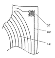
発熱体ユニット27は図3に示すように便座22の着座面26と略相似形をしており、発熱ユニット27の略全面に所定の配設パターンで単線の線状発熱体30を配設してある。配設パターンは、着座した使用者の身体が主に接触する着座面26の範囲に対応する部分に、所定の広い幅の配設ピッチで線状発熱体30を配設して暖房領域42を形成している。本実施の形態においては、暖房領域42の配設ピッチは7mm〜10mmとしている。また、発熱ユニット27の後方の外側部近傍には前記暖房領域42の配設ピッチより狭い1.5mm〜2.5mmの配設ピッチで線状発熱体30を密設した密領域部37を形成している。密領域部37の詳細については別途後述する。
As shown in FIG. 3, the
なお、アルミ箔31の代わりに銅箔などの熱伝導が良好な金属箔を用いても良い。線状発熱体30はフッ素樹脂29により絶縁性及び耐熱性が確保されている。ここで、フッ素樹脂29の代わりにシリコンゴムを用いても良いし、他の材料を用いても絶縁性や耐熱性が確保できるなら何ら問題ない。絶縁性や耐熱性の度合いは求められる暖房便座の性能によって変化する。
Instead of the
着座面26の裏側は、アルマイト処理によりアルマイト層32を形成して絶縁性能を更に高めている。アルマイト層32を形成させる代わりに、ポリイミドやPETなどをフィ
ルム状にしたものを貼付して絶縁性能を高めるという方法でも何ら問題ない。このように絶縁層を2重に設けることで安心安全に暖房便座を使用することができる。着座面26となるアルミニウムの表面には、外観効果のために塗装した表面化粧層33が形成してある。
On the back side of the
また、着座面26の外側表面に施した表面化粧層33は染色処理にすることもできるが、少なくとも着座面26の外側表面に塗装を施せば、防食効果だけでなくアルミなどの金属便座であっても見た感じ冷たい感じを払拭でき、たとえば、真珠のようなパール塗装等によって、やわらかいイメージや高級なイメージを演出することができる。便座22の着座面26に金属しかもアルミニウムのプレス(絞り)加工品を用いたことにより、熱伝導率が約200W/(m・K)と高いため、昇温されると同時に、すばやく着座面26の外側表面つまり表面化粧層33まで熱伝達することができる。しかも、熱伝導率の高いアルミニウムであるため、温度分布をより均一にする均熱効果が得られる。また、アルミニウムのプレス(絞り)加工により加工硬化により板厚を薄くしても必要な強度を確保することができる。たとえば、樹脂の場合は強度の面から3mm程度の肉厚が必要なのに対し、アルミ板の絞り加工品であれば半分の1.5mm以下で十分である。薄くすればするほど、熱容量を少なくできるため、昇温に要する熱量および時間を少なくすることができる。実験の結果、強度と昇温時間の面から、アルミニウムの板厚は0.8〜1.2mmが好ましいという結論を得た。
Further, the surface
さらに、着座面26の裏面には、着座面26の温度を検知するために温度検知センサであるサーミスタ34が取り付けられている。サーミスタ34からの信号は制御部35に伝達され、これらの信号に基づいて採暖面である着座面26の温度が所定の温度になるよう、線状発熱体30への通電が制御されるようになっている。人体検知センサ24はトイレに人が入室したことを検知すると、着座面26の加熱を開始するとともに、便蓋23を開けるように、制御部35へ信号を伝達する。また、本体21の中央部には、便座22への着座を赤外線により検知する着座検知センサ36を有している。たとえば、温水洗浄機能を有した暖房便座では、人の着座を検知した時にのみ、洗浄機能が動作する。
Further, a
上述した構成によって、使用者がトイレに入室した場合には、人体検知センサ24が入室を検知し、その信号が制御部35に送られ、制御部35は線状発熱体30への通電を開始する。制御部35は、通電開始直前のサーミスタ34の温度信号をもとに、便座22の着座面26が適温になるように演算を行い、線状発熱体30への通電を制御する。
With the above-described configuration, when the user enters the toilet, the human
ここで、アルミニウムの板厚を1.0mmとし、線状発熱体30に1200W印加した場合、着座面26の昇温速度は2.5K/sほどである。また、調査によって、使用者がトイレのドアを開けてから着座するまでの所要時間は平均10秒、また、着座面26の温度が29℃以上であれば、着座時に冷感や不快感は覚えないという結果を得た。つまり、冬期のトイレ内が室温5℃であっても、入室と同時に便座を昇温させると、入室から10秒後には着座面26の温度は30℃となり、着座面26の温度を座っても冷たく感じない温度まで昇温させることができる。着座面26に熱伝導が良好なアルミニウムを用いることによって、使用者が便座22に着座するまでの短時間に加温することが可能であるため、使用者が入室していない場合には線状発熱体30に通電する必要がなく、非常に省エネになるとともに、着座面26の均一な加熱が可能であるので快適に使用できる。また、着座時には、着座面26が冷たくない温度まで加温されているので、冷たさを感じることなく快適に使用できる。また、着座面26にアルミニウムの変わりにステンレスを用いることも可能である。ステンレスはアルミに比べて強度が強いため、ステンレスの板厚を薄くすることができるので、熱容量を小さくすることができ、より短時間で加温できるため、更に省エネに優れた暖房便座を実現することができる。
Here, when the plate thickness of aluminum is 1.0 mm and 1200 W is applied to the
次に、使用者が便座22に着座すると、着座検知センサ36の信号により線状発熱体30への通電量をゼロまたは着座面26の温度が過昇しないところまで低減し、適温になるように着座面26の保温を行う。このように着座中も適温に保温されるので快適に使用できる。
Next, when the user is seated on the
暖房便座は着座面26に直接皮膚を接触させて着座するため、安全に対しては十分な配慮が必要である。通常の使用状態では、上述のように安全に快適に使用できるが、万一何らかの異常によりマイコン(図示せず)等、制御部35に不具合が生じ、線状発熱体30への通電制御を行うことができなくなった場合などは、できるだけ早急に安全装置を確実に動作させることが必要となる。本実施の形態では、線状発熱体30の配設パターンに密領域部37を設け、密領域部37にサーモスタット38を取付けた構成としている。そのため、サーモスタット38の温度応答速度を速くさせることができるので、異常時に着座面26の温度が過昇して危険な状態になる前に、線状発熱体30の通電回路をより早く遮断することが可能となり安全に使用できる。
Since the heated toilet seat is seated with the skin directly in contact with the
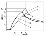
以下、上述の内容を詳しく説明する。図5は、制御部35が故障したことを想定して線状発熱体30に通電した場合のサーモスタット38の検知温度と着座面26の表面温度を測定した結果である。図5において曲線(A)、(A’)は着座面26の表面温度であり、曲線(B)、(B’)はサーモスタット38の検知温度である。線状発熱体30への通電が開始されると、着座面26の表面温度は時間t1で便座最高設定温度(T1)に達する。通常であれば(T1)に達した時点で、制御部35からの指令で通電を停止させるが、何らかの異常が発生した場合は、このまま通電され続ける。サーモスタット38のOFF動作温度が(T3)に設定されていると、着座面26の表面温度が便座最高設定温度(T1)以上であり、確実に異常昇温であると判断できる(T2)に達した時に、サーモスタット38が動作して、線状発熱体30への通電を遮断する。このとき、(t2−t1)秒間過昇温し続けている。ここで、サーモスタット38のOFF動作温度は、物作り面や、コスト面を考慮すると交差0とするのは非常に困難であり、公差は±2℃とするのが一般的である。つまり、公差を考慮するとサーモスタット38のOFF動作温度は(T3)〜(T3+4)となる。OFF動作温度が(T3+4)であれば、着座面26の温度とサーモスタット38の検知温度の曲線は(A’)、(B’)となり、時間t3でサーモスタット38が動作し、回路が遮断される。この場合は(t3−t1)秒間過昇温し続けたこととなる。つまり、サーモスタット38のOFF動作温度のバラツキを考慮すると、過昇温する時間は最短で(t2−t1)秒間、最長で(t3−t1)秒間となる。安全面を考慮すると、過昇温時はできるだけ短時間で回路を遮断しなければならない。そのために、曲線(B)の傾きを大きくする、つまりサーモスタット38の温度応答速度を速くすることによって、時間(t3−t1)を短くすることができ、着座面26の温度が過昇しすぎる前に、線状発熱体30への通電回路を遮断することが可能となり、万が一の時でも安心安全に使用できる。
Hereinafter, the above-described contents will be described in detail. FIG. 5 is a result of measuring the detected temperature of the
このように、密領域部分からサーモスタット38へ受熱する際の放熱ロスを最小限とし、昇温速度をあげることで、OFF動作温度への到達を早め、十分に確実に応答速度を速めることができる。また、この方式で受熱温度を検出することで温度上昇勾配を検知して早いタイミングで線状発熱体30への通電遮断を行うような構成にしてもよい。
In this way, by minimizing heat loss when receiving heat from the dense region portion to the
また、図6に示すように、サーモスタット38の取付け部は感温面と対向するように、渦巻き状にした線状発熱体30を配設し、サーモスタット38の円形状をした感温部(図示せず)と略同一形状にして密領域部37を設けることによって、密領域部37で発生した熱がサーモスタット38へ効率的に伝熱するので、密領域部37に相対する着座面26に極端なホットスポットが生じることがなくなり、着座時に不快感を引き起こすことを防止できる。
Further, as shown in FIG. 6, a
また、サーモスタット38の感温部が方形であれば、例えば図7に示すように線状発熱体30を蛇行させることによって、方形状の密領域部37を形成させても良い。
If the temperature sensing part of the
また、図8に示すように、線状発熱体30の密領域部37に熱伝導ペースト39を塗布してサーモスタット38を取付けることによって、密領域部37で発生した熱を効率よくサーモスタット38へ伝えることができるため、サーモスタット38の応答速度を速めることができるし、線状発熱体30自体の過昇温を防止することができる。また、着座面26側へ流れる熱量も少なくなり密領域部37の相対する着座面26の温度が周囲の温度よりも高くなることを防止することができる。そのため、使用者にとって安全で快適に使用できる暖房便座を提供できる。
Further, as shown in FIG. 8, heat generated in the
熱伝導ペースト39はシリコンオイル等の基油に熱伝導率が高い粉末を配合したものであり、無機材料の粉末や各種金属粉が一般的に使用されているが、その例としてはシリカ、銀、銅、アルミ、アルミナ、窒化ホウ素、窒化アルミ等がある。特に窒化アルミは熱伝導率が高くかつ導電率が低い材料であり、技術的には最適な材料である。熱伝導ペーストの選択は一般的に耐熱温度、熱伝導率、絶縁性能、コストを考慮して最適なものを選択する。
The heat
ここで、密領域部37における線状発熱体30の配設ピッチを狭くすればするほど、密領域部37で発生する熱量が多くなり、サーモスタット38へ伝わる熱量は多くなるので、サーモスタット38の応答速度は速くなる。しかし、ピッチを狭くしすぎると、サーモスタット38の応答速度が速くなる一方で、線状発熱体30の温度は高温となり、ダメージを受けて絶縁不良などの不具合が発生する可能性がある。また、密領域部37に相対する着座面26にホットスポットが生じてしまう可能性がある。そこで、サーモスタット38の応答速度を早くする、線状発熱体30自体に熱衝撃を与えない、着座面26にホットスポットを発生させないという3点を共に満足するために、配設ピッチは1.5mm〜2.5mmとすることが好ましいという結論を実験により得た。
Here, as the arrangement pitch of the
また、密領域部37での発熱量が多くなり、着座面26の温度分布にホットスポットが生じて着座時に感じる不快感を防止するために、図9に示すように、線状発熱体30の密領域部37と着座面26の間に断熱材40を設ける、すなわち着座面の発熱体側絶縁層を介してヒータ線と熱接触することによって、密領域部37の相対する着座面26の温度が周囲の温度よりも高くなることを防止することができる。そのため、使用者にとって快適に使用できる暖房便座を提供できる。
Further, in order to prevent the discomfort felt when sitting because the amount of heat generated in the
本実施の形態では、安全装置としてサーモスタット38を用いているが、安全装置は必ずしもサーモスタット38である必要はなく、温度ヒューズを用いても良いし、温度反応型の安全装置であれば、どのようなものを用いても何ら問題はない。
In the present embodiment, the
なお、安全装置として温度ヒューズを用いる場合について図10に示す。ここでは、温度ヒューズ41の周囲に線状発熱体30を螺旋状に配設することによって、密領域部分を形成することができる。こうすることによって、温度ヒューズ41の温度応答性を速くすることができるので、何らかの異常によって生じる温度過昇を速やかに検知することができ、安全に暖房便座を使用することができる。密領域部分の線状発熱体28間隔は適度に間隙をあけて配設するのが、発熱時に被覆材や貼り付けのための接着部材等を熱破壊することがないので、望ましい。
FIG. 10 shows a case where a thermal fuse is used as the safety device. Here, the dense region portion can be formed by arranging the
(実施の形態2)
図11は、本発明の実施の形態2における線状発熱体からなる発熱体ユニットの概略構
成図を示すものである。本実施の形態は、実施の形態1の発明と基本的な構成は同じで、異なるのはサーモスタット38を取付けるための密領域部37を発熱体ユニット27の後方の両外側部に2箇所設けた構成としていることである。密領域部37には、それぞれオフ動作温度46℃・復帰動作温度35℃となる復帰型サーモスタット(図示せず)と、オフ動作温度が72℃となる非復帰型サーモスタット(図示せず)とが取り付けられている。
(Embodiment 2)
FIG. 11 shows a schematic configuration diagram of a heating element unit composed of a linear heating element in
ここで、2箇所の密領域部37を設け、オフ動作温度が異なる2種類のサーモスタット38を設けた構成としているのは、別部品を用いることによって、万一どちらかのサーモスタット38が不具合を生じたとしても、同時に不具合を起こす確率は少なくなる。そのため、万一制御部35が異常を起こしても、確実に線状発熱体30への通電を遮断することができ、安心安全に暖房便座を使用することができる。
Here, two
また、オフ動作温度が低い方(オフ動作温度46℃)を復帰型とし、オフ動作温度が高い方(オフ動作温度72℃)を非復帰型とした構成としている。こうすることによって、万一制御部35に異常が発生し、線状発熱体30に1200W印加され続けた場合にも、人体に危険が及ぶ前にオフ動作温度が低い方(オフ動作温度46℃)のサーモスタット38によって通電を遮断することができ、安心安全に暖房便座を使用することができる。
In addition, the one having a lower off operation temperature (off operation temperature 46 ° C.) is a return type, and the one having a higher off operation temperature (off operation temperature 72 ° C.) is a non-reset type. In this way, even if an abnormality occurs in the
また、何らかの異常でオフ動作温度が低い方(オフ動作温度46℃)のサーモスタット38が動作しなかった時には、人体に危険が及ぶ温度まで便座が上昇する可能性があるので、オフ動作温度が高い方(オフ動作温度72℃)の非復帰型サーモスタットで通電を遮断し、それ以降は通電されることのないようにすることが可能である。
Further, when the
また、夏期に倉庫など環境温度が70℃程に達する高温環境下で保管されている場合には、オフ動作温度46℃の復帰型サーモスタットは作動するが、オフ動作温度72℃の非復帰型サーモスタットは作動しないため、室温35℃以下である一般家庭内で使用される時には復帰型サーモスタットは復帰しているので、たとえ高温環境下で保管されていたとしても暖房便座を使用することができる。 In addition, when stored in a high temperature environment where the environmental temperature reaches about 70 ° C. such as in a warehouse in the summer, the reset thermostat with an off operation temperature of 46 ° C. operates, but the non-reset thermostat with an off operation temperature of 72 ° C. Since the thermostat does not operate, the reset thermostat is restored when it is used in a general household at a room temperature of 35 ° C. or lower. Therefore, even if the thermostat is stored in a high temperature environment, the heated toilet seat can be used.
本実施の形態では、オフ動作温度46℃・復帰動作温度35℃となる復帰型サーモスタットと、オフ動作温度が72℃となる非復帰型サーモスタットを用いているが、暖房便座が使用される地域の気候に合わせて、オフ動作温度や復帰動作温度の設定を変更する必要がある。 In the present embodiment, a reset thermostat having an off operation temperature of 46 ° C. and a return operation temperature of 35 ° C. and a non-reset thermostat having an off operation temperature of 72 ° C. are used. It is necessary to change the setting of the off operation temperature and the return operation temperature according to the climate.
また、密領域部37を2箇所設けた構成としているが、密領域部37は2箇所である必要はなく、密領域部37を設ければ設けるほど、万一制御部35が異常を起こしたときにサーモスタット38が動作しないという危険性は減少する。密領域部37とサーモスタット38を何箇所設けるかは、求められている暖房便座の性能やコストによって変わってくる。この場合、サーモスタットのオフ動作温度は必ずしも2種類に限定する必要はなく、個別に設定してもよいが、少なくともオフ動作温度の1番高いサーモスタットを非復帰型とし、オフ温度の1番低いサーモスタットを復帰型とすることにより、上記と同様の効果を得ることができる。
In addition, although the
また、実施の形態1と同様に安全装置としてサーモスタットに替えて温度ヒューズを使用してもよいし。またサーモスタットと温度ヒューズを組み合わせて使用してもよい。サーモスタットと温度ヒューズを組み合わせて使用する場合は、サーモスタットは復帰型を使用し、本実施の形態で非復帰型を使用した部分を温度ヒューズに替えて使用することが最適である。 As in the first embodiment, a thermal fuse may be used as a safety device instead of the thermostat. A thermostat and a thermal fuse may be used in combination. When a thermostat and a thermal fuse are used in combination, it is optimal to use a reset type thermostat and replace the portion using the non-reset type in this embodiment with a thermal fuse.
特にサーモスタットと温度ヒューズを併用する場合は、サーモスタットは密領域部に設置し、温度ヒューズは実施の形態1に記載の方法で設置してもよいし、温度ヒューズの別の設置方法として、温度ヒューズを直接または絶縁チューブ内に挿設する等の処置を施すことで温度ヒューズを包囲し、絶縁および防水処置を施した温度ヒューズを発熱体ユニットの暖房領域の下面に粘着テープ等を介して設置することも考えられる。 In particular, when a thermostat and a thermal fuse are used in combination, the thermostat may be installed in a dense region, and the thermal fuse may be installed by the method described in the first embodiment. The thermal fuse is surrounded by applying a measure such as directly or in the insulation tube, and the thermal fuse that has been insulated and waterproofed is placed on the lower surface of the heating area of the heating element unit with adhesive tape or the like. It is also possible.
以上のように、本発明の暖房便座は、線状発熱体を密に配設した部分に安全装置を取付けることによって、温度変化を速やかに検知でき、安全に使用し得る暖房便座が得られ、使用者が着座する機器の暖房技術として適用することが可能である。 As described above, the heating toilet seat of the present invention can quickly detect a temperature change by attaching a safety device to a portion where the linear heating elements are densely arranged, and a heating toilet seat that can be used safely is obtained. The present invention can be applied as a heating technique for a device on which a user is seated.
22 便座
26 着座面
30 線状発熱体
34 サーミスタ(温度検知センサ)
35 制御部
37 密領域部
38 サーモスタット(安全装置)
39 熱伝導ペースト
50 ノズル装置
22
35
39 Thermal
Claims (10)
前記着座面の裏側内面に配設した線状発熱体と、
前記着座面の温度を検知する温度検知センサと、
前記線状発熱体への通電量を制御する制御部と、
前記着座面の温度過昇を防止する温度反応型の安全装置とを備え、
前記線状発熱体の配設パターンは、着座した使用者の身体が主に接触する着座面に対応する範囲に設けた配設ピッチ部と、
前記範囲の配設ピッチ部より狭いピッチからなる密領域部とを有しており、
前記密領域部を前記範囲より外側でかつ着座した使用者の身体が接触しにくい範囲に配置し、
前記密領域部に前記安全装置を設けたことを特徴とした暖房便座。 A toilet seat formed of metal at least a part of a seating surface that the body contacts when sitting;
A linear heating element disposed on the inner surface of the back side of the seating surface;
A temperature detection sensor for detecting the temperature of the seating surface;
A control unit for controlling the amount of energization to the linear heating element;
A temperature-responsive safety device that prevents the seating surface from overheating,
The arrangement pattern of the linear heating elements is an arrangement pitch portion provided in a range corresponding to a seating surface on which a user's body seated mainly comes in contact;
A dense region portion having a narrower pitch than the arrangement pitch portion of the range ,
The dense area is placed outside the range and in a range where the user's body seated is difficult to contact ,
A heating toilet seat, wherein the safety device is provided in the dense region.
Priority Applications (1)
| Application Number | Priority Date | Filing Date | Title |
|---|---|---|---|
| JP2007020828A JP4775275B2 (en) | 2006-08-10 | 2007-01-31 | Heating toilet seat and toilet device equipped with it |
Applications Claiming Priority (3)
| Application Number | Priority Date | Filing Date | Title |
|---|---|---|---|
| JP2006218039 | 2006-08-10 | ||
| JP2006218039 | 2006-08-10 | ||
| JP2007020828A JP4775275B2 (en) | 2006-08-10 | 2007-01-31 | Heating toilet seat and toilet device equipped with it |
Publications (3)
| Publication Number | Publication Date |
|---|---|
| JP2008062016A JP2008062016A (en) | 2008-03-21 |
| JP2008062016A5 JP2008062016A5 (en) | 2011-02-17 |
| JP4775275B2 true JP4775275B2 (en) | 2011-09-21 |
Family
ID=39285230
Family Applications (1)
| Application Number | Title | Priority Date | Filing Date |
|---|---|---|---|
| JP2007020828A Active JP4775275B2 (en) | 2006-08-10 | 2007-01-31 | Heating toilet seat and toilet device equipped with it |
Country Status (1)
| Country | Link |
|---|---|
| JP (1) | JP4775275B2 (en) |
Cited By (1)
| Publication number | Priority date | Publication date | Assignee | Title |
|---|---|---|---|---|
| JP2016144553A (en) * | 2015-02-09 | 2016-08-12 | パナソニックIpマネジメント株式会社 | Toilet seat device |
Families Citing this family (3)
| Publication number | Priority date | Publication date | Assignee | Title |
|---|---|---|---|---|
| JP5104663B2 (en) * | 2008-08-29 | 2012-12-19 | パナソニック株式会社 | Toilet seat device and sanitary washing device using the same |
| JP6344641B2 (en) * | 2014-03-17 | 2018-06-20 | Toto株式会社 | Heating toilet seat device |
| CN105411467B (en) * | 2014-09-09 | 2019-09-27 | 松下知识产权经营株式会社 | Seat device |
Family Cites Families (6)
| Publication number | Priority date | Publication date | Assignee | Title |
|---|---|---|---|---|
| JPH0443731A (en) * | 1990-06-08 | 1992-02-13 | Fujitsu Ltd | Television data multiplexing and demultiplexing system |
| JPH06176853A (en) * | 1992-12-07 | 1994-06-24 | Matsushita Electric Ind Co Ltd | Floor heating panel |
| JPH09121717A (en) * | 1995-11-07 | 1997-05-13 | Gutsupii:Kk | Heater for water tank and attachment tool for preventing overheat |
| JP2000106264A (en) * | 1998-09-30 | 2000-04-11 | Canon Inc | Heater, image-heating device, fixing device, and image- forming device |
| JP2001299645A (en) * | 2000-04-25 | 2001-10-30 | Matsushita Electric Works Ltd | Heated toilet seat |
| JP4635438B2 (en) * | 2004-01-09 | 2011-02-23 | パナソニック株式会社 | Heating toilet seat |
-
2007
- 2007-01-31 JP JP2007020828A patent/JP4775275B2/en active Active
Cited By (1)
| Publication number | Priority date | Publication date | Assignee | Title |
|---|---|---|---|---|
| JP2016144553A (en) * | 2015-02-09 | 2016-08-12 | パナソニックIpマネジメント株式会社 | Toilet seat device |
Also Published As
| Publication number | Publication date |
|---|---|
| JP2008062016A (en) | 2008-03-21 |
Similar Documents
| Publication | Publication Date | Title |
|---|---|---|
| JP2008253747A5 (en) | ||
| JP4775275B2 (en) | Heating toilet seat and toilet device equipped with it | |
| JP2010075497A (en) | Toilet seat device and bidet apparatus using the same | |
| JP4513301B2 (en) | Heating toilet seat | |
| JP4635438B2 (en) | Heating toilet seat | |
| JP4946467B2 (en) | Heating toilet seat | |
| JP4967805B2 (en) | Heating toilet seat | |
| JP2005192896A5 (en) | ||
| JP6090704B2 (en) | Heating toilet seat | |
| JP6467626B2 (en) | Toilet seat device | |
| JP4784053B2 (en) | Heating toilet seat | |
| JP2008110089A (en) | Warm toilet seat, and warm water bidet device provided with the same | |
| JP2007252942A (en) | Heated toilet seat | |
| JP2008110089A5 (en) | ||
| JP2007143717A (en) | Heated toilet seat device | |
| JP2000232952A (en) | Warming closet seat | |
| JP5176831B2 (en) | Toilet seat device | |
| JP6347048B2 (en) | Toilet seat device | |
| JP2011010800A (en) | Toilet seat device | |
| JP4067008B2 (en) | Heating toilet seat | |
| JP4513300B2 (en) | Heating toilet seat | |
| JP2010051672A (en) | Toilet seat heater and heated toilet seat using the same | |
| JP5104663B2 (en) | Toilet seat device and sanitary washing device using the same | |
| JP2002262961A (en) | Seat with plane heater | |
| JP2010029256A (en) | Toilet seat device and sanitary washer using the same |
Legal Events
| Date | Code | Title | Description |
|---|---|---|---|
| A621 | Written request for application examination |
Free format text: JAPANESE INTERMEDIATE CODE: A621 Effective date: 20081105 |
|
| RD01 | Notification of change of attorney |
Free format text: JAPANESE INTERMEDIATE CODE: A7421 Effective date: 20091127 |
|
| A977 | Report on retrieval |
Free format text: JAPANESE INTERMEDIATE CODE: A971007 Effective date: 20101217 |
|
| A521 | Written amendment |
Free format text: JAPANESE INTERMEDIATE CODE: A523 Effective date: 20101224 |
|
| A871 | Explanation of circumstances concerning accelerated examination |
Free format text: JAPANESE INTERMEDIATE CODE: A871 Effective date: 20101224 |
|
| A975 | Report on accelerated examination |
Free format text: JAPANESE INTERMEDIATE CODE: A971005 Effective date: 20110107 |
|
| A131 | Notification of reasons for refusal |
Free format text: JAPANESE INTERMEDIATE CODE: A131 Effective date: 20110118 |
|
| A521 | Written amendment |
Free format text: JAPANESE INTERMEDIATE CODE: A523 Effective date: 20110318 |
|
| TRDD | Decision of grant or rejection written | ||
| A01 | Written decision to grant a patent or to grant a registration (utility model) |
Free format text: JAPANESE INTERMEDIATE CODE: A01 Effective date: 20110531 |
|
| A01 | Written decision to grant a patent or to grant a registration (utility model) |
Free format text: JAPANESE INTERMEDIATE CODE: A01 |
|
| A61 | First payment of annual fees (during grant procedure) |
Free format text: JAPANESE INTERMEDIATE CODE: A61 Effective date: 20110613 |
|
| R151 | Written notification of patent or utility model registration |
Ref document number: 4775275 Country of ref document: JP Free format text: JAPANESE INTERMEDIATE CODE: R151 |
|
| FPAY | Renewal fee payment (event date is renewal date of database) |
Free format text: PAYMENT UNTIL: 20140708 Year of fee payment: 3 |