JP4635438B2 - Heating toilet seat - Google Patents
Heating toilet seat Download PDFInfo
- Publication number
- JP4635438B2 JP4635438B2 JP2004003849A JP2004003849A JP4635438B2 JP 4635438 B2 JP4635438 B2 JP 4635438B2 JP 2004003849 A JP2004003849 A JP 2004003849A JP 2004003849 A JP2004003849 A JP 2004003849A JP 4635438 B2 JP4635438 B2 JP 4635438B2
- Authority
- JP
- Japan
- Prior art keywords
- toilet seat
- heating element
- temperature
- heating
- element unit
- Prior art date
- Legal status (The legal status is an assumption and is not a legal conclusion. Google has not performed a legal analysis and makes no representation as to the accuracy of the status listed.)
- Expired - Fee Related
Links
Images


Description
本発明は、暖房機能を有する便座に関するものである。 The present invention relates to a toilet seat having a heating function.
従来この種の暖房便座では、図10に示すように内部に空洞部1を持つ樹脂製の便座2の着座部3の裏面にコード状のヒーター4をアルミテープ5などで接着固定したものが一般に用いられている。しかし、この暖房便座は、樹脂製の便座2の着座部3を所定の温度まで加熱するのに長時間を要するため、ヒーター4には常時通電しており、無駄な電力の消費が多かった。
Conventionally, in this type of heated toilet seat, a cord-like heater 4 is generally bonded and fixed to the back surface of a seating portion 3 of a
このような無駄な電力消費を削減するために、タイマーによって暖房時間を設定するか、一定時間以上使用されない場合はヒーター4への通電を停止する暖房便座もある。しかし、このような便座は、設定した暖房時間帯で使用されていない間合いでも電力が消費されていたのに加え、暖房時間外に使用した場合は便座が暖房されていないという問題があった。 In order to reduce such wasteful power consumption, there is also a heating toilet seat that sets a heating time by a timer or stops energization of the heater 4 when it is not used for a certain period of time. However, such a toilet seat has a problem that the toilet seat is not heated when it is used outside the heating time, in addition to being consumed even when it is not used in the set heating time zone.
また、コード状のヒーター4は細いため便座2の着座部3の裏面全体に設置することは困難なため、ヒーター4の直上と、ヒーター4の無い部分では温度差が生じていた。
Further, since the cord-like heater 4 is thin, it is difficult to install the cord-like heater 4 on the entire back surface of the seating portion 3 of the
これを解決するために、図11に示す瞬間暖房式の暖房便座が提案されている。これはステンレス製の着座面6の裏面に絶縁部材7を介して面状発熱体8、断熱材9、反射体10を加熱押圧して便座本体11に固着形成したものである。面状発熱体8は、ステンレスをパターニングして繰り返し蛇行するように這わせて均一な加熱を実現し、また、断熱材9、反射体10を設けることにより熱の散逸を防止し、着座面6に効果的に伝熱させ着座面6が早く温度上昇するので、図10に示す従来の暖房便座に比べ、格段に電力消費量を低減することができるというものであった(例えば特許文献1参照)。
In order to solve this problem, an instant heating type heating toilet seat shown in FIG. 11 has been proposed. In this case, a sheet heating element 8, a heat insulating material 9, and a
しかしながら、前記従来の構成では、着座面6を短時間で暖房することができる一方、着座面6の温度を制御する温度制御手段(図示せず)に何らかの不具合が生じた場合には温度過昇防止装置が温度の異常を検知するまで時間的な遅れが生じるため、着座面6の温度が上がり過ぎる場合があった。また、便座本体11、反射体10、断熱材9、面状発熱体8、絶縁部材7、着座面6を隙間無く重ねて固着した構成としているため、反射体10では輻射熱は反射できるものの、熱伝導により面状発熱体8からの熱が便座本体11に散逸するため、着座面6を加熱する効率が低下するという課題があった。
前記従来の課題に鑑み、本発明が解決しようとする課題は、使用者が便座の着座面に着座するまでの短時間に着座面を均一に加熱するとともに、着座面の温度が上がり過ぎることがない安全な暖房便座を提供することにある。 In view of the above-described conventional problems, the problem to be solved by the present invention is that the seating surface is heated uniformly and the temperature of the seating surface increases excessively in a short time until the user sits on the seating surface of the toilet seat. There is no safe heating toilet seat to provide.
前記従来の課題を解決するために、本発明の暖房便座は、少なくとも着座部を金属で形成した便座と、前記便座の裏面に設け、面状に形成した発熱体ユニットと、前記発熱体ユニットの一部と前記着座部との間に間隙を形成して構成した断熱部と、前記断熱部を構成する前記発熱体ユニットの一部の前記間隙側と対向する側に異常温度上昇を検知して回路
を遮断する温度過昇防止装置を備えたものである。
In order to solve the above-described conventional problems, a heating toilet seat according to the present invention includes a toilet seat in which at least a seating portion is formed of metal, a heating element unit provided on a back surface of the toilet seat and formed in a planar shape, and the heating element unit. An abnormal temperature rise is detected on the side of the heat-insulating part configured to form a gap between a part and the seating part, and the side of the part of the heat generating unit constituting the heat-insulating part facing the gap side. This is provided with an overheat prevention device for interrupting the circuit.
これによって、発熱体が着座面を面状に加熱するので、着座面が均一に加熱されるとともに、発熱体から発生した熱はほとんど金属の着座部の加熱に使われるので、着座部を効率よく加熱できる。また、着座部との間に間隙を形成するように断熱部を設けているので
、便座加熱時、発熱体ユニットの断熱部に対応する部分を他部よりも早く温度上昇させて温度過昇防止装置により、着座面の温度の上がり過ぎを防止できる。
As a result, the heating element heats the seating surface in a planar shape, so that the seating surface is heated uniformly, and the heat generated from the heating element is mostly used for heating the metal seating part, so the seating part can be efficiently used. Can be heated. In addition, since a heat insulating part is provided so as to form a gap with the seating part, when the toilet seat is heated, the temperature of the part corresponding to the heat insulating part of the heating element unit is raised faster than other parts to prevent overheating. The apparatus can prevent the temperature of the seating surface from rising too much.
本発明の暖房便座は、着座部を均一に加熱し快適な使用感が得られるとともに、使用時に即座に着座部を加熱することができ、無駄な電力消費を削減することができる。また、着座部の温度の上がり過ぎを防止できる。 The heated toilet seat according to the present invention can uniformly heat the seating portion to obtain a comfortable feeling of use, and can immediately heat the seating portion during use, thereby reducing wasteful power consumption. Further, it is possible to prevent the temperature of the seating portion from rising excessively.
第1の発明は、少なくとも着座部を金属で形成した便座と、前記便座の裏面に設け、面状に形成した発熱体ユニットと、前記発熱体ユニットの一部と前記着座部との間に間隙を形成して構成した断熱部と、前記断熱部を構成する前記発熱体ユニットの一部の前記間隙側と対向する側に異常温度上昇を検知して回路を遮断する温度過昇防止装置を備えた暖房便座である。 According to a first aspect of the present invention, there is provided a toilet seat having at least a seating portion formed of metal, a heating element unit provided on the back surface of the toilet seat and formed in a planar shape, and a gap between a part of the heating element unit and the seating portion. and the heat insulating portion configured to form a thermal cut-to cut off the circuit to detect an abnormal temperature rise on the side facing the part of the gap side of the heating element unit constituting the heat insulating portion It is a heated toilet seat.
これにより、面状の発熱体によって着座部が均一に加熱されるので快適な使用感が得られる。また、発熱体から発生した熱は、ほとんど金属の着座部の加熱に使われるので、着座部を効率よく加熱し、使用者が便座の着座面に着座するまでの短時間に着座面を加熱することができ、無駄な電力消費を削減することができる。 Thereby, since a seating part is uniformly heated by a planar heating element, a comfortable feeling of use is obtained. Also, the heat generated from the heating element is mostly used to heat the metal seat, so the seat is heated efficiently and the seat is heated in a short time until the user sits on the seat. And wasteful power consumption can be reduced.
また、着座部との間に間隙を形成するように断熱部を設けて発熱体ユニットから発生する熱の着座部への熱伝導を抑制するので、断熱部に対応した発熱体ユニットの温度過昇防止装置を設けた部分を、他部よりも早く温度上昇させることができ、例えば着座部の温度を制御する温度制御手段に何らかの不具合が生じた場合でも、温度過昇防止装置の応答を早くして着座部の温度の上がりすぎを防止することができる。 In addition, since a heat insulating portion is provided so as to form a gap between the heat generating unit and the seating portion, heat conduction from the heat generating unit to the seating portion is suppressed. It is possible to raise the temperature of the part provided with the prevention device faster than the other parts.For example, even if some trouble occurs in the temperature control means for controlling the temperature of the seating part, the response of the overtemperature prevention device is made faster. Thus, the temperature of the seating portion can be prevented from rising too much.
第2の発明は、特に第1の発明の断熱部を形成する間隙に、断熱体を設けた構成とすることにより、発熱体ユニットから発生する熱の着座部への熱伝導を抑制するので、断熱部に対応する発熱体ユニットの温度過昇防止装置を設けた部分を、他部よりも早く温度上昇させることができ、例えば着座部の温度を制御する温度制御手段に何らかの不具合が生じた場合でも、温度過昇防止装置の応答を早くして着座部の温度の上がりすぎを防止することができる。また、断熱体を設けることにより断熱部の形状を安定させるので、温度過昇防止装置の動作を安定させることができる。 Since the second aspect of the invention suppresses heat conduction to the seating part of the heat generated from the heating element unit by providing a heat insulator in the gap forming the heat insulating part of the first aspect of the invention, The part of the heating element unit corresponding to the heat insulating part provided with the overheat prevention device can be heated faster than the other parts, for example, when some trouble occurs in the temperature control means for controlling the temperature of the seating part However, the response of the over-temperature prevention device can be accelerated to prevent the temperature of the seating portion from rising excessively. Moreover, since the shape of a heat insulation part is stabilized by providing a heat insulating body, the operation | movement of a temperature rise prevention apparatus can be stabilized.
第3の発明は、少なくとも着座部を金属で形成した便座と、前記便座の裏面に設け、面状に形成した発熱体ユニットと、前記便座内の一部に断熱材を介して設けた第2の発熱体ユニットと、前記第2の発熱体ユニットに設け、異常温度上昇を検知して回路を遮断する温度過昇防止装置を備えた暖房便座である。 According to a third aspect of the present invention, there is provided a toilet seat in which at least a seating portion is made of metal, a heating element unit formed on a back surface of the toilet seat and formed in a planar shape, and a second portion provided in a part of the toilet seat via a heat insulating material. And a heating toilet seat provided in the second heat generating unit and provided with an overtemperature preventing device that detects an abnormal temperature rise and interrupts the circuit.
これにより、面状の発熱体によって着座部が均一に加熱されるので快適な使用感が得られる。また、発熱体から発生した熱はほとんど金属の着座部の加熱に使われるので、着座部を効率よく加熱し、使用者が便座の着座面に着座するまでの短時間に着座面を加熱することができ、無駄な電力消費を削減することができる。 Thereby, since a seating part is uniformly heated by a planar heating element, a comfortable feeling of use is obtained. Also, most of the heat generated from the heating element is used to heat the metal seat, so the seat must be heated efficiently and the seat must be heated in a short time before the user sits on the seat. It is possible to reduce wasteful power consumption.
さらに、便座内の一部に断熱材を介して設けられた第2の発熱体ユニットに異常温度上昇を検知して回路を遮断する温度過昇防止装置を備えたことにより、第2の発熱体ユニットから発生する熱は断熱材によって熱伝導が抑制されるので第2の発熱体ユニットを発熱体ユニットよりも早く温度上昇させることができ、例えば着座部の温度を制御する温度制御手段に何らかの不具合が生じた場合でも、温度過昇防止装置の応答を早くして着座部の温度の上がり過ぎを防止することができる。 Further, the second heating element is provided with an overtemperature preventing device for detecting an abnormal temperature rise and shutting off the circuit in the second heating element unit provided in a part of the toilet seat via a heat insulating material. The heat generated from the unit is suppressed in heat conduction by the heat insulating material, so that the temperature of the second heating element unit can be raised faster than that of the heating element unit. For example, there is some problem in the temperature control means for controlling the temperature of the seating portion. Even when this occurs, the response of the overheat prevention device can be accelerated to prevent the temperature of the seating portion from rising excessively.
第4の発明は、特に第3の発明における第2の発熱体ユニットの電力密度を、発熱体ユニットの電力密度より高くした構成とすることにより、第3の発明の構成よりも早く第2の発熱体ユニットの温度を上昇させることができ、例えば着座部の温度を制御する温度制御手段に何らかの不具合が生じた場合でも、温度過昇防止装置の応答をさらに早くして着座部の温度の上がり過ぎを防止することができる。 According to the fourth aspect of the invention, in particular, the power density of the second heat generating unit in the third aspect of the invention is set to be higher than the power density of the heat generating unit. The temperature of the heating element unit can be increased. For example, even if a problem occurs in the temperature control means for controlling the temperature of the seating section, the response of the overheating prevention device is further accelerated to increase the temperature of the seating section. It can be prevented.
第5の発明は、特に第1〜第4の発明のいずれか1つの発明の温度過昇防止装置を、バイメタル式のサ−モスタットとすることにより、短時間で着座部を暖めるために大電流を必要とする場合にも対応ができるとともに、金属の熱膨張率の差を利用した物理的動作で温度過昇防止装置を作動するため安定した動作を得ることができる。 In the fifth aspect of the invention, in particular, the overheat prevention device according to any one of the first to fourth aspects of the invention is a bimetal thermostat, so that a large current can be used to warm the seating portion in a short time. Therefore, a stable operation can be obtained because the overheat prevention device is operated by a physical operation utilizing the difference in thermal expansion coefficient between metals .
本発明の目的は、第1の発明から第5の発明を実施の形態の要部とすることにより達成できるので、各請求項に対応する実施の形態の詳細を、以下に図面を参照しながら説明し、本発明を実施するための最良の形態の説明とする。なお、この実施の形態によって本発明が限定されるものではない。また、本実施の形態の説明において、同一構成並びに作用効果を奏するところには同一符号を付して重複した説明を行わないものとする。 The object of the present invention can be achieved by using the first to fifth aspects of the present invention as the main part of the embodiment, so the details of the embodiment corresponding to each claim will be described below with reference to the drawings. It will be described and the best mode for carrying out the present invention will be described. In addition, this invention is not limited by this embodiment. Further, in the description of the present embodiment, the same reference numerals are given to the same configuration and the effects and the same description is not repeated.
(実施の形態1)
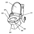
図1は本発明の実施の形態1における暖房便座の概略断面図で、図2は同暖房便座を搭載したトイレの斜視図で、図3は同暖房便座の発熱体ユニットの概略構成図で、図4は同暖房便座の温度過昇防止装置部分の要部断面図である。図1および図2において、便器20に本体21が取り付けられており、この本体21に暖房機能を有する本発明の便座22および便蓋23が回動自在に設けられている。また、本体21の袖部にはトイレ空間の人体の有無を検知する赤外線センサ24が内装されている。
(Embodiment 1)
1 is a schematic sectional view of a heating toilet seat according to Embodiment 1 of the present invention, FIG. 2 is a perspective view of a toilet equipped with the heating toilet seat, and FIG. 3 is a schematic configuration diagram of a heating element unit of the heating toilet seat, FIG. 4 is a cross-sectional view of an essential part of the overheat prevention device portion of the heating toilet seat. 1 and 2, a
便座22は、合成樹脂製の便座ベ−ス25とステンレス、アルミニウム等で形成された金属性の着座部26からなり、2つの部材をそれぞれの内周縁および外周縁で接合することによって形成し、その内部には水等の浸入を阻止できる密閉された空洞部27を有する構造となっている。
The
上記空洞部27には、便座22の着座部26の裏面に設けた発熱体ユニット28が備えられている。この発熱体ユニット28に接触もしくは近接して発熱体ユニット28と直列に接続された温度過昇防止装置であるサーモスタット29および温度ヒューズ30が設けられており、万一の不安全事態に対して便座22の温度過昇を防止するよう作用する。着座部26の内面にはサーミスタ31が設けられ、着座部26の温度を検知する。
The
本体21には、室温検知手段として室温サーミスタ32が設けられ、サーミスタ31、室温サーミスタ32からの信号はそれぞれマイクロコンピュータ等からなる制御部33に伝達され、これらの信号に基づいて採暖面である着座部26の温度が所定の温度になるよう、発熱体ユニット28への通電が制御部33により制御されるようになっている。
The
赤外線センサ24は、使用者がトイレに入室した場合それを検知し、着座部26の加熱を開始するとともに便蓋23の開閉を行う。また、便座22の底面にはマイクロスイッチ34で構成された着座検知手段35を有しており、便座22への加重でスイッチがオンすることにより使用者の着座を検知するようになっている。例えば、温水洗浄機能を有した暖房便座では、人の着座を検知した時にのみ、洗浄機能が動作する。
The
発熱体ユニット28は、図3に示すように0.1mmの板厚のステンレスを蛇行状にパターニングして形成した発熱体36の両端に電極37を形成し、これにリード線38を溶着した構成としており、さらに、発熱体36の上下両面にフィルム状の絶縁体である上部
絶縁体39と下部絶縁体40を接着している。絶縁体としては、可撓性に優れたPPやPETなどの熱可塑性樹脂が使用できる。また、耐熱性が要求される場合は、ポリイミドが好適である。
The
また、温度過昇防止装置であるサーモスタット29は、図4に示すように発熱体ユニット28の一部と着座部26との間に間隙41を介して形成した断熱部42を設け、この断熱部42に対応した部分の発熱体ユニット28に、感熱部43を接触させて設け、異常温度上昇を検知して発熱体ユニット28の通電回路を遮断するものである。
Further, as shown in FIG. 4, the
そして、サーモスタット29は一般に用いられているバイメタル式が利用可能である。バイメタル式サーモスタットは、使用者が便座の着座面に着座するまでの短時間で着座部26を暖めるために大電流を必要とする場合にも対応ができるとともに、金属の熱膨張率の差を利用した物理的動作で温度過昇防止装置を作動するため安定した動作を得ることができる。
The
上記構成において、使用者がトイレに入室した場合、赤外線センサ24がそれを検知し、その信号が制御部33に送られ、制御部33は発熱体36に通電を開始する。制御部33には、便座22の発熱体36に通電することにより昇温を開始した時点からの経過時間をカウントするタイマー部44が設けられている。
In the above configuration, when the user enters the toilet, the
制御部33は、通電開始時のサーミスタ31および室温サーミスタ32の信号をもとに、両者の温度差やそれぞれの温度から演算を行い、あらかじめ設定・記憶されている通電制限時間の最適値を選択し、タイマー部44でカウントしている経過時間が通電制限時間に到達すると通電量を低減または零にし、その後サーミスタ31の信号をもとに便座22の着座部26が適温になるよう通電量を制御する。
Based on the signals of the
そして、制御部33はサーミスタ31が実際に使用者が触れる着座部26の温度を検知しているので、精度良く適温まで昇温・維持するので快適であり、さらにサーミスタ31および室温サーミスタ32の信号をもとに負荷量に合わせて電力の投入量を制御するので、より精度良く安全に適温まで加熱することができる。また、付勢時間制御を優先的に行うことで通電制限時間後は通電量を低減し昇温速度を減ずるので、温度検知手段の応答速度が遅くても安全に便座を加温することができる。
Since the
次に、使用者が排便のために着座すると、着座検知手段35の信号により発熱体36への通電量を零または便座温度が過昇しないところまで低減する。これにより、サーミスタ31などが故障しても使用中に便座温度が過昇することなく、火傷等が生じる心配なく安全である。加えて、便座22への着座直前だけ便座加温を行うので、非常に省エネになるものである。
Next, when the user is seated for defecation, the energization amount to the
なお、ここでは着座検知手段35をマイクロスイッチ34で構成したもので説明したが、回動自在に設けた便座22のヒンジ部等に設けても良く、その場所や構成は種々のものが考えられる。
Here, the seat detection means 35 has been described as being constituted by the
便座22は、熱伝導が良好な金属製の着座部26を有しており、使用者が便座22に着座するまでの極短時間に加温することができるので、ヒーターを常時通電しておくことなく非常に省エネになるとともに、発熱体36は面形状であるため、均一な加熱が可能である。また、便座22内部は空洞部27としているため、空気による断熱効果によって発熱体から発生した熱はほとんど金属の着座部26の加熱に使われるので、着座部26を効率よく加熱し、使用者が便座に着座するまでの短時間に着座部を加熱することができ、無駄な電力消費を削減することができる。
The
以上の説明において、サーミスタ31、室温サーミスタ32、および着座検知手段35によって、便座温度は過昇することは無いと述べたが、本実施の形態では使用者が便座22に着座するまでの極短時間で加温するために、大電力を投入することから、さらに安全に対する配慮を行っている。例えば万一、制御部33に異常が発生した場合でもサーモスタット29で温度の異常を検知して発熱体ユニット28への通電回路自体を遮断し、便座温度の過昇を回避することができる。
In the above description, the toilet seat temperature is not excessively increased by the
温度ヒューズ30は、さらにサーモスタット29に不具合が生じた時の安全策として設けられている。図5はサーミスタ31、室温サーミスタ32、着座検知手段35をショートした状態で発熱体ユニット28に通電した場合の温度上昇を示したものである。図5において、曲線(A)は着座部26の表面温度特性であり、室温15℃では発熱体ユニット28への入力約1.0W/cm2の場合、約6秒で通常の便座制御温度(T1)までの昇温が可能である。一方、断熱部42に設けられたサーモスタット29の感熱部43の温度特性は曲線(B)に示すように、断熱部42では着座部26への熱の移動が少ないため着座部26より速くt1時間で便座制御温度(T1)まで上昇する。
The
感熱部43の温度は、さらにサーモスタット29のオフ動作温度(T2)に達するが、実際にはサーモスタット29に内蔵されているバイメタル45(後述)の温度がオフ動作温度(T2)に達するまでに遅れが生じることから、実際にオフ動作が行われるのはt2時間後である。このように遅れが生じても、着座部26よりも感熱部43の温度が速く昇温するので、着座部26の表面温度が安全限界温度(T3)に達する前に便座温度の異常を検出することができ、火傷等を起こすこと無く、安全に発熱体ユニットの通電回路を遮断することができる。
The temperature of the
また、断熱部42は、図6に示すように間隙41に断熱体46を挿入する構成としても良い。断熱体46としては必ずしも断熱性の高いセラミック系の材料でなくても良く、硬質の発泡樹脂やPP、PETなど一般的な熱可塑性樹脂材料が使用可能である。このように間隙41に断熱体46を挿入して断熱部42を構成することで、断熱部42の形状を安定させられ、サーモスタット29を断熱部42に安定して固定できるとともに、断熱部42と着座部26の形状を規定するので着座部26の温度と断熱部42(すなわち、感熱部43)との温度差のばらつきを小さくすることができ、温度の異常検知を安定して行うことができる。
Moreover, the
以上のように本実施の形態では、面状の発熱体により着座部を均一に加熱できるので快適な使用感が得られるとともに、発熱体から発生した熱はほとんど金属の着座部の加熱に使われるので、着座部を効率よく加熱し、使用者が便座の着座部に着座するまでの短時間に着座部を加熱することができ、無駄な電力消費を削減することができる。また、着座部との間に間隙を形成するように断熱部を設けて発熱体ユニットから発生する熱の着座部への熱伝導を抑制するので断熱部に対応する部分を他部よりも早く温度上昇させられるため温度過昇防止装置の応答を早くすることができる。 As described above, in the present embodiment, since the seating portion can be uniformly heated by the planar heating element, a comfortable feeling of use can be obtained, and the heat generated from the heating element is mostly used for heating the metal seating portion. Therefore, the seating portion can be efficiently heated, and the seating portion can be heated in a short time until the user is seated on the seating portion of the toilet seat, and wasteful power consumption can be reduced. In addition, a heat insulating part is provided so as to form a gap with the seating part to suppress heat conduction from the heat generating unit to the seating part, so that the part corresponding to the heat insulating part is heated earlier than the other parts. Since the temperature is raised, the response of the overheat prevention device can be accelerated.
(実施の形態2)
図7は、本発明の実施の形態2における暖房便座の概略断面図である。本実施の形態は、温度過昇防止装置を、着座部を加熱する発熱体ユニットとは別個に便座内に設けた第2の発熱体ユニットに設けた点で実施の形態1の発明と異なり、それ以外の構成並びに作用効果は同じであり、前記異なる点を中心に説明する。
(Embodiment 2)
FIG. 7 is a schematic cross-sectional view of the heating toilet seat according to
図7に示す構成は、便座22内の一部に断熱材47を介して第2の発熱体ユニット48を設け、前記第2の発熱体ユニット48に温度過昇防止装置であるサーモスタット29を
設けた構成としている。第2の発熱体ユニット48は面状に形成した第2の発熱体49の上下両面にフィルム状の第1絶縁体50および第2絶縁体51を接着して形成し、発熱体ユニット28と直列に接続して通電回路を構成している。
In the configuration shown in FIG. 7, a second
第2の発熱体ユニット48を設ける位置は、任意であるが、図7では便座ベース25の一部に設けている。そして、第2の発熱体ユニット48は、電力密度を発熱体ユニット28の電力密度より高く設定している。サーモスタット29は、感熱部43を第2の発熱体ユニット48に接触させているが、サーモスタット29を下向きに設定することにより、感熱部43とバイメタル45の間隔が最小となるように構成している。
Although the position where the second
すなわち、バイメタル式サーモスタット29は通常、図8に示すように、円盤状で湾曲したバイメタル45がキャップ52内に収納され、温度上昇によってバイメタルを構成する金属の熱膨張率の差によりバイメタル45が反転し、その時ピン53を押し下げることによって接点(図示せず)を開にして前記通電回路を遮断する構成となっている。バイメタル45とキャップ52間には間隔dが形成されており、急激な温度変化を感知する場合は、この間隔dが大きいとバイメタル45とキャップ52の表面(すなわち感熱部43)との間に温度差が生じ、サーモスタット29の動作に遅れが生じる場合がある。図7の実施の形態では、サーモスタット29を下向きに設定することにより、キャップ52とバイメタル45の間隔dを最小もしくは両者を接触させることにより、サーモスタット29の動作遅れを低減するので、温度異常時に速やかに、かつ安全に第2の発熱体ユニット29の通電回路を遮断することができる。
That is, in the
図9は、図5に示した特性と同様の評価を図7に示す暖房便座の構成で実施した結果である。室温15℃で発熱体ユニット28への入力の電力密度を約1.0W/cm2、第2の発熱体ユニット48への入力の電力密度を1.2W/cm2とし、着座部26と感熱部43の温度を測定した。曲線(C)は着座部26の表面温度特性、曲線(D)は感熱部43の温度特性を示す。このように第2の発熱体ユニット48への入力の電力密度を、発熱体ユニット28への入力の電力密度より高くすることにより、感熱部43の温度特性は図5の曲線(A)の場合より早く時間t3で通常の便座制御温度(T1)に達する。
FIG. 9 is a result of performing the same evaluation as the characteristics shown in FIG. 5 with the configuration of the heated toilet seat shown in FIG. The power density of the input to the
またサーモスタット29は、下向きに設定して第2の発熱体ユニット48に設け、感熱部43とバイメタル45の間隔が最小となるように構成しているので、サーモスタット29の動作遅れを低減することができ、図5の曲線(A)よりも速い時間t4でかつ、低い温度で発熱体ユニット28の通電回路を遮断することができる。このとき着座部26の温度は、図9に示すように図5の曲線(A)よりも低い温度で回路が遮断されており、従って図7に示す暖房便座の構成では、より早く、かつ低い温度で安全に回路を遮断することができる。
Further, since the
なお、上記各実施の形態では発熱体36および第2の発熱体49を0.1mmの板厚のステンレスをパターニングして形成したものについて説明したが、これに限ったものではなく、例えばパンチングメタル等を利用したものでも良く、また発熱体36および第2の発熱体49を別の工法で製作しても良い。また、上記各実施の形態では着座部26の全体を金属で形成したが、少なくとも使用者の尻が着座する部分だけ金属であっても良いものである。
In each of the above embodiments, the
以上のように本発明にかかる暖房便座は、着座部を均一に加熱し快適な使用感が得られるとともに、使用時に即座に着座部を加熱することができ、無駄な電力消費を削減することができ、かつ着座部の温度の上がり過ぎを防止でき、使用者が着座する機器の暖房技術として適用することが可能である。 As described above, the heated toilet seat according to the present invention can uniformly heat the seating portion to obtain a comfortable feeling of use and can immediately heat the seating portion during use, thereby reducing wasteful power consumption. It is possible to prevent the temperature of the seating portion from rising excessively, and it can be applied as a heating technique for a device on which a user is seated.
22 便座
26 着座部
28 発熱体ユニット
29 サーモスタット(温度過昇防止装置)
36 発熱体
41 間隙
42 断熱部
43 感熱部
45 バイメタル
46 断熱体
47 断熱材
48 第2の発熱体ユニット
22
36
Claims (5)
前記便座の裏面に設け、面状に形成した発熱体ユニットと、
前記発熱体ユニットの一部と前記着座部との間に間隙を形成して構成した断熱部と、
前記断熱部を構成する前記発熱体ユニットの一部の前記間隙側と対向する側に異常温度上昇を検知して回路を遮断する温度過昇防止装置を備えた暖房便座。 A toilet seat with at least a seating portion made of metal,
A heating element unit provided on the back surface of the toilet seat and formed in a planar shape;
A heat insulating part configured by forming a gap between a part of the heating element unit and the seating part;
A heating toilet seat provided with an overheat prevention device for detecting an abnormal temperature rise and shutting off a circuit on a side facing the gap side of a part of the heat generating unit constituting the heat insulating portion.
前記便座の裏面に設け、面状に形成した発熱体ユニットと、
前記便座内の一部に断熱材を介して設けた第2の発熱体ユニットと、
前記第2の発熱体ユニットに異常温度上昇を検知して回路を遮断する温度過昇防止装置を備えた暖房便座。 A toilet seat with at least a seating portion made of metal,
A heating element unit provided on the back surface of the toilet seat and formed in a planar shape;
A second heating element unit provided in a part of the toilet seat via a heat insulating material;
A heating toilet seat provided with an over-temperature prevention device that detects an abnormal temperature rise in the second heating element unit and interrupts the circuit.
Priority Applications (1)
| Application Number | Priority Date | Filing Date | Title |
|---|---|---|---|
| JP2004003849A JP4635438B2 (en) | 2004-01-09 | 2004-01-09 | Heating toilet seat |
Applications Claiming Priority (1)
| Application Number | Priority Date | Filing Date | Title |
|---|---|---|---|
| JP2004003849A JP4635438B2 (en) | 2004-01-09 | 2004-01-09 | Heating toilet seat |
Related Child Applications (2)
| Application Number | Title | Priority Date | Filing Date |
|---|---|---|---|
| JP2007133730A Division JP2007252942A (en) | 2007-05-21 | 2007-05-21 | Heated toilet seat |
| JP2007133729A Division JP4967805B2 (en) | 2007-05-21 | 2007-05-21 | Heating toilet seat |
Publications (3)
| Publication Number | Publication Date |
|---|---|
| JP2005192896A JP2005192896A (en) | 2005-07-21 |
| JP2005192896A5 JP2005192896A5 (en) | 2007-02-22 |
| JP4635438B2 true JP4635438B2 (en) | 2011-02-23 |
Family
ID=34818631
Family Applications (1)
| Application Number | Title | Priority Date | Filing Date |
|---|---|---|---|
| JP2004003849A Expired - Fee Related JP4635438B2 (en) | 2004-01-09 | 2004-01-09 | Heating toilet seat |
Country Status (1)
| Country | Link |
|---|---|
| JP (1) | JP4635438B2 (en) |
Cited By (1)
| Publication number | Priority date | Publication date | Assignee | Title |
|---|---|---|---|---|
| KR101817740B1 (en) * | 2016-06-17 | 2018-02-22 | (주) 파루 | Plane heater for toilet seat |
Families Citing this family (10)
| Publication number | Priority date | Publication date | Assignee | Title |
|---|---|---|---|---|
| JP4742830B2 (en) * | 2005-11-24 | 2011-08-10 | パナソニック株式会社 | Heating toilet seat and toilet device equipped with it |
| JP4742897B2 (en) * | 2006-02-14 | 2011-08-10 | パナソニック株式会社 | Heating toilet seat |
| JP4742905B2 (en) * | 2006-02-23 | 2011-08-10 | パナソニック株式会社 | Heating toilet seat |
| WO2007125662A1 (en) * | 2006-04-28 | 2007-11-08 | Panasonic Corporation | Sanitary washing device |
| JP2008023141A (en) * | 2006-07-24 | 2008-02-07 | Matsushita Electric Ind Co Ltd | Warmed toilet seat |
| JP4775275B2 (en) * | 2006-08-10 | 2011-09-21 | パナソニック株式会社 | Heating toilet seat and toilet device equipped with it |
| JP4737033B2 (en) * | 2006-10-26 | 2011-07-27 | パナソニック電工株式会社 | Bonding structure between metal molded product and resin plate |
| JP5405729B2 (en) | 2007-03-12 | 2014-02-05 | パナソニック株式会社 | Toilet seat device |
| JP4821695B2 (en) * | 2007-04-25 | 2011-11-24 | パナソニック株式会社 | Toilet seat device and sanitary washing device using the same |
| JP5597910B2 (en) * | 2007-09-28 | 2014-10-01 | パナソニック株式会社 | Heating toilet seat and toilet device equipped with it |
Citations (2)
| Publication number | Priority date | Publication date | Assignee | Title |
|---|---|---|---|---|
| JP2000232952A (en) * | 1999-02-15 | 2000-08-29 | Hitachi Chem Co Ltd | Warming closet seat |
| JP2003141978A (en) * | 2001-11-07 | 2003-05-16 | Koito Ind Ltd | Circuit breaker and heated toilet stool seat |
-
2004
- 2004-01-09 JP JP2004003849A patent/JP4635438B2/en not_active Expired - Fee Related
Patent Citations (2)
| Publication number | Priority date | Publication date | Assignee | Title |
|---|---|---|---|---|
| JP2000232952A (en) * | 1999-02-15 | 2000-08-29 | Hitachi Chem Co Ltd | Warming closet seat |
| JP2003141978A (en) * | 2001-11-07 | 2003-05-16 | Koito Ind Ltd | Circuit breaker and heated toilet stool seat |
Cited By (1)
| Publication number | Priority date | Publication date | Assignee | Title |
|---|---|---|---|---|
| KR101817740B1 (en) * | 2016-06-17 | 2018-02-22 | (주) 파루 | Plane heater for toilet seat |
Also Published As
| Publication number | Publication date |
|---|---|
| JP2005192896A (en) | 2005-07-21 |
Similar Documents
| Publication | Publication Date | Title |
|---|---|---|
| JP4635438B2 (en) | Heating toilet seat | |
| JP4967805B2 (en) | Heating toilet seat | |
| JP4513301B2 (en) | Heating toilet seat | |
| JP2005192896A5 (en) | ||
| JP6090704B2 (en) | Heating toilet seat | |
| JP2007252942A (en) | Heated toilet seat | |
| JP4775275B2 (en) | Heating toilet seat and toilet device equipped with it | |
| JP2005218538A (en) | Heating toilet seat and toilet device mounted therewith | |
| JP4946467B2 (en) | Heating toilet seat | |
| JP2008110089A (en) | Warm toilet seat, and warm water bidet device provided with the same | |
| JP3952068B2 (en) | Heating toilet seat and toilet device equipped with it | |
| JP2008110089A5 (en) | ||
| JP4513300B2 (en) | Heating toilet seat | |
| JP2563600B2 (en) | Heating toilet seat | |
| JP6467626B2 (en) | Toilet seat device | |
| JP2000232952A (en) | Warming closet seat | |
| JP4784053B2 (en) | Heating toilet seat | |
| JP2011010800A (en) | Toilet seat device | |
| JP2003125981A (en) | Heated toilet seat | |
| JP2009106568A (en) | Toilet seat apparatus | |
| JP5050630B2 (en) | Toilet seat device and toilet device including the same | |
| JP4067008B2 (en) | Heating toilet seat | |
| JP5176831B2 (en) | Toilet seat device | |
| JP2563599B2 (en) | Heating toilet seat | |
| JP4569130B2 (en) | Heating toilet seat |
Legal Events
| Date | Code | Title | Description |
|---|---|---|---|
| A521 | Written amendment |
Free format text: JAPANESE INTERMEDIATE CODE: A523 Effective date: 20070105 |
|
| A621 | Written request for application examination |
Free format text: JAPANESE INTERMEDIATE CODE: A621 Effective date: 20070105 |
|
| RD01 | Notification of change of attorney |
Free format text: JAPANESE INTERMEDIATE CODE: A7421 Effective date: 20070214 |
|
| A977 | Report on retrieval |
Free format text: JAPANESE INTERMEDIATE CODE: A971007 Effective date: 20090915 |
|
| A131 | Notification of reasons for refusal |
Free format text: JAPANESE INTERMEDIATE CODE: A131 Effective date: 20090929 |
|
| A521 | Written amendment |
Free format text: JAPANESE INTERMEDIATE CODE: A523 Effective date: 20091030 |
|
| RD01 | Notification of change of attorney |
Free format text: JAPANESE INTERMEDIATE CODE: A7421 Effective date: 20091120 |
|
| A131 | Notification of reasons for refusal |
Free format text: JAPANESE INTERMEDIATE CODE: A131 Effective date: 20100518 |
|
| A521 | Written amendment |
Free format text: JAPANESE INTERMEDIATE CODE: A523 Effective date: 20100630 |
|
| TRDD | Decision of grant or rejection written | ||
| A01 | Written decision to grant a patent or to grant a registration (utility model) |
Free format text: JAPANESE INTERMEDIATE CODE: A01 Effective date: 20101026 |
|
| A01 | Written decision to grant a patent or to grant a registration (utility model) |
Free format text: JAPANESE INTERMEDIATE CODE: A01 |
|
| A61 | First payment of annual fees (during grant procedure) |
Free format text: JAPANESE INTERMEDIATE CODE: A61 Effective date: 20101108 |
|
| FPAY | Renewal fee payment (event date is renewal date of database) |
Free format text: PAYMENT UNTIL: 20131203 Year of fee payment: 3 |
|
| R151 | Written notification of patent or utility model registration |
Ref document number: 4635438 Country of ref document: JP Free format text: JAPANESE INTERMEDIATE CODE: R151 |
|
| FPAY | Renewal fee payment (event date is renewal date of database) |
Free format text: PAYMENT UNTIL: 20131203 Year of fee payment: 3 |
|
| LAPS | Cancellation because of no payment of annual fees |