JP4774301B2 - Catenary train line - Google Patents
Catenary train line Download PDFInfo
- Publication number
- JP4774301B2 JP4774301B2 JP2006010962A JP2006010962A JP4774301B2 JP 4774301 B2 JP4774301 B2 JP 4774301B2 JP 2006010962 A JP2006010962 A JP 2006010962A JP 2006010962 A JP2006010962 A JP 2006010962A JP 4774301 B2 JP4774301 B2 JP 4774301B2
- Authority
- JP
- Japan
- Prior art keywords
- wire
- line
- carbon fiber
- trolley
- catenary
- Prior art date
- Legal status (The legal status is an assumption and is not a legal conclusion. Google has not performed a legal analysis and makes no representation as to the accuracy of the status listed.)
- Expired - Fee Related
Links
Images


Description
本発明は、温度変化による張力の変動を緩和する張力調整装置を必要とせず、引留間隔を延長することのできるカテナリ式電車線に関するものである。 The present invention relates to a catenary-type train line that does not require a tension adjusting device that relieves fluctuations in tension due to a temperature change and can extend a holding interval.
一般に、電気鉄道のカテナリ式の架線構造においては、トロリ線やちょう架線に銅線や鋼線が使用されており、例えば、銅の線膨張係数は17×10−6 [/℃]であり、鋼の線膨張係数は12×10−6 [/℃]である。このため、これらの金属線を使用した場合、温度変化による電線の伸縮を吸収するために、最大で約1.6km間隔でトロリ線とちょう架線を引留めるとともに、引留箇所にバネ式或いは滑車式の自動張力調整装置を設置して弛みを吸収することが行われていた。 In general, in the catenary overhead wire structure of electric railways, copper wires and steel wires are used for the trolley wire and the overhead wire, for example, the linear expansion coefficient of copper is 17 × 10 −6 [/ ° C.] The linear expansion coefficient of steel is 12 × 10 −6 [/ ° C.]. For this reason, when these metal wires are used, in order to absorb the expansion and contraction of the electric wire due to temperature changes, the trolley wire and the overhead wire are retained at intervals of about 1.6 km at the maximum, and the spring type or pulley type is used at the retention point. The automatic tension adjusting device was installed to absorb slack.
図7は、従来のカテナリ式電車線の一例を示す説明図、図8は、従来のカテナリ式電車線のちょう架線の支持構造を示す説明図である。ここで、カテナリ式電車線は、引留柱1、1間にちょう架線2とトロリ線3をそれぞれ自動張力調整装置4、5を介して張り渡していた。また、ちょう架線2は、所定間隔に設置した支柱6によってガイシ7を介して支持金具8で波形に吊り上げていた。トロリ線3は、ちょう架線2から垂下されたハンガー9によって、水平な状態につり下げられている。図8は、支柱6におけるちょう架線2の支持構造を拡大して示している。この従来例において、ちょう架線2は、支持金具8によって下から持ち上げるようにして支えられている。また、引留柱1の間隔(引留間隔)は、最大で約1.6kmであった。
更に、特許文献1や特許文献2には、カテナリ式でトロリ線を剛体にして両方式の長所を取り入れたカテナリ式剛体電車線が提案されている。
Further,
しかし従来のカテナリ式電車線では、以下のような解決すべき課題がある。
1)ちょう架線やトロリ線に鋼線や銅線を使用しており、温度変化による伸縮を吸収するための自動張力調整装置が不可欠であった。このため多くの複雑な部品構成となり、保守、点検に手間がかかった。また、引留間隔も最大で約1.6kmであり、これ以上長くすることができなかった。したがって、設備費もかさむ不利があった。
2)また、鋼線や銅線は重量が嵩み設備自体の大型化が避けられず、建設コストの削減や高速化への容易な対応ができなかった。さらに、支持点に於けるちょう架線とトロリ線との高低差である架高が高いために、支柱の長さが長くなって、設備費が増大する不利もあった。
また、特許文献1、2に開示されたカテナリ式剛体電車線においてもちょう架線に鋼線を使用しているために、同様の課題が存在する。
However, the conventional catenary train line has the following problems to be solved.
1) Steel wires and copper wires were used for the overhead wire and trolley wire, and an automatic tension adjusting device to absorb expansion and contraction due to temperature changes was indispensable. For this reason, many complicated parts are required, and maintenance and inspection are time-consuming. Further, the maximum length of the retention interval is about 1.6 km, which cannot be further increased. Therefore, there was a disadvantage that the equipment cost was also increased.
2) Also, steel wires and copper wires are heavy and the size of the equipment itself cannot be increased, making it impossible to easily reduce construction costs and increase speed. Furthermore, since the height of the rack, which is the height difference between the butterfly line and the trolley line at the support point, is high, there is a disadvantage that the length of the column becomes long and the equipment cost increases.
Moreover, in the catenary type rigid train line disclosed in
この発明は上記に鑑み提案されたもので、曲率半径の大きな支持面を有する支持金具を使用して曲げを最小限にして、ちょう架線に線膨張係数が低く、重量の軽いカーボンファイバ線を使用することで、自動張力調整装置を不要にし、引留間隔を延伸することを目的とするものである。 The present invention has been proposed in view of the above, using a support metal fitting having a support surface with a large radius of curvature to minimize bending, and using a carbon fiber wire having a low coefficient of linear expansion and a light weight for the overhead wire. By doing so, an automatic tension adjusting device is not required, and the object is to extend the retention interval.
前記目的を達成するために、本発明は引留柱間に張り渡されるとともに、所定間隔で設置した支柱によって支持金具で吊り上げられたちょう架線と、前記ちょう架線から垂下されたハンガーによってレールに対して水平に張り渡されたトロリ線とから成るカテナリ式電車線であって、前記トロリ線は、硬銅トロリ線にカーボンファイバ線を沿わせた構成とされ、所定間隔に配置したハンガイヤーで両者が固定されるとともに、前記カーボンファイバ線には、架設時に前記硬銅トロリ線より大きな張力を付与したことを特徴としている。 In order to achieve the above-mentioned object, the present invention is stretched between retaining pillars and is suspended from a support line by a support bracket by pillars installed at a predetermined interval, and to a rail by a hanger suspended from the support line. It is a catenary train line consisting of a trolley line stretched horizontally, and the trolley line has a carbon fiber line along a hard copper trolley line, and both are fixed with hanger ears arranged at a predetermined interval. In addition, the carbon fiber wire is characterized in that a greater tension than that of the hard copper trolley wire is applied to the carbon fiber wire .
また、本発明において前記ちょう架線はカーボンファイバで構成され、前記支持金具は、ちょう架線を支える支持面が所定の曲率半径の円弧状をなして、前記ちょう架線を支持することを特徴とする。 In the present invention, the overhead wire is made of carbon fiber, and the support fitting supports the overhead wire with a support surface that supports the overhead wire having an arc shape with a predetermined curvature radius .
また、本発明において前記トロリ線は、中間材を介してカーボンファイバ線をハンガイヤーで固定したことを特徴とする。 In the present invention, the trolley wire is characterized in that a carbon fiber wire is fixed by a hanger through an intermediate material.
また、本発明において前記ハンガイヤーは、前記ハンガイヤーは、ちょう架線から垂下されたハンガーによって支持されるとともに、前記中間材は弾性部材であることを特徴とするものである。 In the present invention, the hanger ear is characterized in that the hanger ear is supported by a hanger suspended from a butterfly wire, and the intermediate member is an elastic member .
この発明は前記した構成からなるので、以下に説明するような効果を奏することができる。 Since this invention consists of an above-described structure, there can exist an effect which is demonstrated below.
本発明では、引留柱間に張り渡されるとともに、所定間隔で設置した支柱によって支持金具で吊り上げられたちょう架線と、前記ちょう架線から垂下されたハンガーによってレールに対して水平に張り渡されたトロリ線とから成るカテナリ式電車線であって、前記ちょう架線をカーボンファイバで構成したため、温度変化による伸縮量が小さくなり自動張力調整装置を設置する必要がない。また、カーボンファイバ線を支持する支持金具が大きな曲率半径の支持面で支えるので、無理な曲げが作用することなく断線の虞れもない。また、前記トロリ線は、硬銅トロリ線とその真上に配置されたカーボンファイバ線とから構成され、所定間隔に配置したハンガイヤーで一体的に固定したので、温度変化による伸縮量が小さくなり自動張力調整装置を設置する必要がない。また、電車線の軽量化が図られ、高速化に対応することができる。更に、架高が低いので支柱が短くて済み、建設コストの大幅な削減が達成できる。また、架線のメンテナンス性も向上する。 In the present invention, the trolley is stretched between the retaining pillars and is lifted by the support bracket by the support columns installed at predetermined intervals, and the trolley stretched horizontally with respect to the rail by the hanger hanging from the overhead line. Since the cable is a catenary-type train line composed of a wire and the overhead wire is made of carbon fiber, the amount of expansion and contraction due to temperature change is reduced, and there is no need to install an automatic tension adjusting device. In addition, since the support fitting that supports the carbon fiber wire is supported by a support surface having a large radius of curvature, there is no possibility of disconnection without excessive bending. In addition, the trolley wire is composed of a hard copper trolley wire and a carbon fiber wire arranged immediately above it, and is fixed integrally with a hanger ear arranged at a predetermined interval, so that the amount of expansion and contraction due to temperature change is reduced and automatic There is no need to install a tension adjustment device. In addition, the weight of the train line can be reduced and the speed can be increased. Furthermore, since the height of the rack is low, the length of the support can be shortened, and the construction cost can be greatly reduced. In addition, maintainability of the overhead wire is improved.
また、本発明では、前記トロリ線は、中間材を介してカーボンファイバ線をハンガイヤーで固定したので、線材が保護されるとともにカーボンファイバ線の引き抜け力を確保することができる。 In the present invention, since the trolley wire has the carbon fiber wire fixed by the hanger through the intermediate material, the wire material is protected and the pull-out force of the carbon fiber wire can be secured.
また、本発明では、前記トロリ線は、硬銅トロリ線の張力を低減し、カーボンファイバ線に張力を付与したので、引留箇所で線条の伸縮を吸収する必要がなく、自動張力調整装置を設置する必要がない。したがって、設備費を大幅に削減することができる。また、前記ハンガイヤーは、ちょう架線から垂下されたハンガーによって支持されるとともに、弾性部材である中間材によってカーボンファイバ線を固定するので、線材が保護されるとともにカーボンファイバ線の引き抜け力を確保することができる。 In the present invention, the trolley wire reduces the tension of the hard copper trolley wire and imparts tension to the carbon fiber wire. There is no need to install. Therefore, the facility cost can be greatly reduced. In addition, the hanger ear is supported by a hanger suspended from the suspension wire, and the carbon fiber wire is fixed by an intermediate material that is an elastic member, so that the wire material is protected and the pull-out force of the carbon fiber wire is secured. be able to.
本発明のカテナリ式電車線を実施するための最良の形態について、図面を参照して説明する。図1は、本発明に係るカテナリ式電車線の一例を示す説明図、図2は、本実施の形態のカテナリ式電車線におけるちょう架線の支持構造を示す説明図である。ここで、カテナリ式電車線10は、引留柱11、11間に張り渡されるとともに、所定間隔で設置した支柱12、12によって支持金具13で吊り上げられたちょう架線14と、このちょう架線14から垂下されたハンガー15によってレール(図示せず)に対して水平に張り渡されたトロリ線16とから構成されている。
The best mode for carrying out the catenary train line of the present invention will be described with reference to the drawings. FIG. 1 is an explanatory diagram illustrating an example of a catenary train line according to the present invention, and FIG. 2 is an explanatory diagram illustrating a support structure of a overhead line in the catenary train line of the present embodiment. Here, the catenary-
ちょう架線14は、カーボンファイバ線から構成されている。カーボンファイバ線は、線膨張係数が0.6×10⁻⁶ [/℃]であり温度変化による伸縮量が非常に小さい。このため、引留箇所での線条の伸縮を吸収する必要がなく、自動張力調整装置を設置する必要がない。
The
支持金具13は、図2に示すようにちょう架線14を支える支持面が大きな曲率半径を有しており、カーボンファイバ線を吊り上げる際にカテナリ形状に沿った、最小限の曲げ曲線となるように構成する。また、ちょう架線14は、支持金具13で支持されている。このようにカーボンファイバ線14は、支持金具13によって面で支持され、急激な曲げ応力が作用しない。また、支持金具13は、絶縁ガイシ17を介して支柱12に支持されたトラスビーム18に吊り下げられる。
As shown in FIG. 2, the support fitting 13 has a large curvature radius on the support surface that supports the
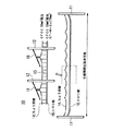
図3は、本実施の形態同カテナリ式電車線におけるトロリ線の支持構造を示す説明図、図4は、本実施の形態のカテナリ式電車線におけるトロリ線のハンガイヤー部の縦断面図である。トロリ線16は、硬銅トロリ線19とその真上に配置されたカーボンファイバ線20とから構成され、所定間隔に配置したハンガイヤー21で一体的に固定されている。硬銅トロリ線19は、通常の硬銅製であり、カーボンファイバ線20はカーボンファイバ樹脂から造られている。また、トロリ線16は、ゴム、合成樹脂等の中間材22を介してカーボンファイバ線20を長手方向にずれないように固定している。更に、トロリ線16は、硬銅トロリ線19を無張力とし、カーボンファイバ線20に張力を付与する。また、ハンガイヤー21は、ちょう架線14から垂下されたハンガー15によって支持されるとともに、ゴム等の弾性部材である中間材22によってカーボンファイバ線20を固定する。
FIG. 3 is an explanatory view showing a support structure of the trolley line in the catenary train line according to the present embodiment, and FIG. 4 is a vertical cross-sectional view of the hanger ear portion of the trolley line in the catenary train line according to the present embodiment. The
このように構成されたカテナリ式電車線は、温度変化による伸縮量が非常に小さいので自動張力調整装置を設置する必要がない。また、カーボンファイバ線の曲げを最小限としたので、断線の虞もない。更に、温度変化による伸縮量が小さいので、引留間隔を延伸することができる。 The catenary train line configured in this way has a very small amount of expansion and contraction due to a temperature change, so it is not necessary to install an automatic tension adjusting device. In addition, since the bending of the carbon fiber wire is minimized, there is no possibility of disconnection. Furthermore, since the amount of expansion and contraction due to temperature change is small, the retention interval can be extended.
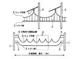
次に、本発明の実施例について説明する。図5は、ちょう架線にカーボンファイバを使用した場合と硬銅より線(PH)を使用した場合の温度と張力の関係を示す図である。本実施例では自動張力調整装置を設置することなく、張力変化率を算出したものである。ちょう架線には、直径7.5mm(断面積30.4mm2)のカーボンファイバ線と、硬銅より線(PH)(断面積356mm2)を19.6[kN]で架設した。初期温度が15℃で、初期張力が19.6kNで架設したときの温度と張力の関係は、図5に示す通りである。15℃から±30℃の温度変化があった場合の張力変化は、カーボンファイバ線の場合が、19.527kN〜19.673kN(−0.4%〜+0.4%)であった。これに対して、硬銅より線(PH)の場合は、14.14kN〜26.23kN(−28%〜+34%)であった。
以上のように、カーボンファイバ線の張力変化率は、±0.4%であり、現行架線で自動張力調整装置を使用した際の張力変化率±15%と比較しても大幅に小さいものであった。
Next, examples of the present invention will be described. FIG. 5 is a diagram showing the relationship between temperature and tension when a carbon fiber is used for the butterfly wire and when a hard copper strand (PH) is used. In this embodiment, the tension change rate is calculated without installing an automatic tension adjusting device. A carbon fiber wire having a diameter of 7.5 mm (cross-sectional area of 30.4 mm 2 ) and a hard copper strand (PH) (cross-sectional area of 356 mm 2 ) were installed at 19.6 [kN] on the overhead wire. The relationship between temperature and tension when the initial temperature is 15 ° C. and the initial tension is 19.6 kN is as shown in FIG. The change in tension when the temperature changed from 15 ° C. to ± 30 ° C. was 19.527 kN to 19.673 kN (−0.4% to + 0.4%) for the carbon fiber wire. On the other hand, in the case of a stranded copper wire (PH), it was 14.14 kN to 26.23 kN (-28% to + 34%).
As described above, the rate of change in tension of the carbon fiber wire is ± 0.4%, which is much smaller than the rate of change in tension of ± 15% when using the automatic tension adjuster with the current overhead wire. there were.
図6は、トロリ線にカーボンファイバと硬銅トロリ線を使用した場合と硬銅トロリ線のみを使用した場合の温度と張力の関係を示す図である。本実施例では、トロリ線に、直径7.5mm(断面積30.4mm2)のカーボンファイバ線を、14.7kNで架設し、その下にGT−M−Sn170mm2 を無張力で架設する。初期温度15℃、初期張力14.7kNで架設した際の温度と張力の関係は、図6に示す通りである。ここで明らかな様に、初期温度以上の場合、張力はすべてカーボンファイバが担うために、張力低下は非常に少ない。15℃から±30℃の温度変化があった場合の張力変化は、カーボンファイバ線+硬銅トロリ線の場合が、14.625kN〜25.07kN(−0.5%〜+70%)であった。一方。硬銅トロリ線(GT−M−Sn)のみの場合、4.55N〜25.03kN(−69%〜+70%)であった。
以上のように、カーボンファイバ線の張力低下率は、−0.5%であり、現行架線に自動張力調整装置を設置した場合の張力変化率±15%と比較しても大幅に小さく、大きく弛むことはなかった。
FIG. 6 is a diagram showing the relationship between temperature and tension when a carbon fiber and a hard copper trolley wire are used as the trolley wire and when only a hard copper trolley wire is used. In this embodiment, a carbon fiber wire having a diameter of 7.5 mm (cross-sectional area of 30.4 mm 2 ) is installed on the trolley wire at 14.7 kN, and GT-M-Sn 170 mm 2 is installed below it with no tension. FIG. 6 shows the relationship between temperature and tension when installed at an initial temperature of 15 ° C. and an initial tension of 14.7 kN. As apparent from the above, when the temperature is equal to or higher than the initial temperature, all the tension is borne by the carbon fiber, so that the decrease in tension is very small. The change in tension when the temperature changed from 15 ° C to ± 30 ° C was 14.625 kN to 25.07 kN (-0.5% to + 70%) in the case of carbon fiber wire + hard copper trolley wire. . on the other hand. In the case of only a hard copper trolley wire (GT-M-Sn), it was 4.55N to 25.03 kN (-69% to + 70%).
As described above, the tension reduction rate of the carbon fiber wire is -0.5%, which is much smaller and larger than the tension change rate ± 15% when the automatic tension adjusting device is installed on the current overhead wire. There was no sag.
10 カテナリ式電車線
11 引留柱
12 支柱
13 支持金具
14 ちょう架線
15 ハンガー
16 トロリ線
17 絶縁ガイシ
18 トラスビーム
19 硬銅トロリ線
20 カーボンファイバ線
21 ハンガイヤー
22 中間材
DESCRIPTION OF
Claims (4)
前記トロリ線は、硬銅トロリ線にカーボンファイバ線を沿わせた構成とされ、所定間隔に配置したハンガイヤーで両者が固定されるとともに、
前記カーボンファイバ線には、架設時に前記硬銅トロリ線より大きな張力を付与したことを特徴とするカテナリ式電車線。 It is stretched between the retaining pillars, and is composed of a suspension line that is lifted by a support bracket by pillars installed at a predetermined interval, and a trolley line that is stretched horizontally with respect to the rail by a hanger suspended from the suspension line. A catenary train line,
The trolley wire has a configuration in which a carbon fiber wire is aligned with a hard copper trolley wire, and both are fixed by a hanger ear arranged at a predetermined interval,
A catenary train line , wherein a tension greater than that of the hard copper trolley wire is applied to the carbon fiber wire.
前記支持金具は、ちょう架線を支える支持面が所定の曲率半径の円弧状をなして、前記ちょう架線を支持することを特徴とする請求項1に記載のカテナリ式電車線。 The overhead wire is made of carbon fiber,
2. The catenary train line according to claim 1, wherein the support metal supports the platform line by forming a support surface supporting the platform line in an arc shape with a predetermined curvature radius . 3.
中間材を介して前記カーボンファイバ線をハンガイヤーで前記硬銅トロリ線に固定したことを特徴とする請求項1または2に記載のカテナリ式電車線。 The trolley wire is
The catenary train line according to claim 1 or 2, wherein the carbon fiber wire is fixed to the hard copper trolley wire with a hanger through an intermediate material.
Priority Applications (1)
| Application Number | Priority Date | Filing Date | Title |
|---|---|---|---|
| JP2006010962A JP4774301B2 (en) | 2006-01-19 | 2006-01-19 | Catenary train line |
Applications Claiming Priority (1)
| Application Number | Priority Date | Filing Date | Title |
|---|---|---|---|
| JP2006010962A JP4774301B2 (en) | 2006-01-19 | 2006-01-19 | Catenary train line |
Publications (2)
| Publication Number | Publication Date |
|---|---|
| JP2007191032A JP2007191032A (en) | 2007-08-02 |
| JP4774301B2 true JP4774301B2 (en) | 2011-09-14 |
Family
ID=38447061
Family Applications (1)
| Application Number | Title | Priority Date | Filing Date |
|---|---|---|---|
| JP2006010962A Expired - Fee Related JP4774301B2 (en) | 2006-01-19 | 2006-01-19 | Catenary train line |
Country Status (1)
| Country | Link |
|---|---|
| JP (1) | JP4774301B2 (en) |
Families Citing this family (3)
| Publication number | Priority date | Publication date | Assignee | Title |
|---|---|---|---|---|
| US11745624B2 (en) | 2015-12-11 | 2023-09-05 | Ctc Global Corporation | Messenger wires for electric trains, methods for making and methods for installation |
| CN106049895B (en) * | 2016-07-26 | 2018-09-18 | 福州大学 | A kind of FRP ruggedized constructions improving existing reinforced concrete structure catenary effect |
| GB2585214B (en) * | 2019-07-02 | 2024-02-07 | Brecknell Willis & Co Ltd | Overhead line system |
Family Cites Families (9)
| Publication number | Priority date | Publication date | Assignee | Title |
|---|---|---|---|---|
| JPS4933769Y1 (en) * | 1970-03-26 | 1974-09-12 | ||
| JPS4995306A (en) * | 1973-01-16 | 1974-09-10 | ||
| JPS6171532A (en) * | 1984-09-14 | 1986-04-12 | Hokuto Denshi Kogyo Kk | Method and equipment for manufacturing explosion-proof cathode-ray tube |
| JPH04334629A (en) * | 1991-05-09 | 1992-11-20 | Sumitomo Electric Ind Ltd | Trolley wire |
| JPH08154318A (en) * | 1994-11-28 | 1996-06-11 | Sumitomo Electric Ind Ltd | Overhead transmission line, cable hanger device and stringing method of cable |
| JPH0946837A (en) * | 1995-07-31 | 1997-02-14 | East Japan Railway Co | Optical composite overhead earth-wire line for railroad |
| JPH0998528A (en) * | 1995-09-29 | 1997-04-08 | Furukawa Electric Co Ltd:The | Multiple-conductor transmission line |
| JP2001270348A (en) * | 2000-03-28 | 2001-10-02 | Railway Technical Res Inst | Overhead wire supporting device |
| JP3811471B2 (en) * | 2003-07-02 | 2006-08-23 | 東日本旅客鉄道株式会社 | Insulated overhead wire |
-
2006
- 2006-01-19 JP JP2006010962A patent/JP4774301B2/en not_active Expired - Fee Related
Also Published As
| Publication number | Publication date |
|---|---|
| JP2007191032A (en) | 2007-08-02 |
Similar Documents
| Publication | Publication Date | Title |
|---|---|---|
| US9205761B2 (en) | Suspension apparatus and method for contact wire at crest of a track vertical curve | |
| JP4774301B2 (en) | Catenary train line | |
| US9731626B2 (en) | Device having two rigid conductor rails and a section insulator | |
| US2149875A (en) | Cable support | |
| WO2015092413A1 (en) | Overhead electrification line cantilever assembly | |
| JP4861259B2 (en) | Section insulator | |
| KR101810796B1 (en) | rigid bar transition device for high speed electric railroad | |
| JP5833949B2 (en) | Trolley wire overlap structure | |
| JP6372037B2 (en) | Trolley wire support structure | |
| CN205915979U (en) | Low clearance tunnel contact net twin elbow cantilever supporting structure | |
| JP6529864B2 (en) | Jumper wire V suspension system and method of forming jumper wire | |
| KR100733976B1 (en) | A tunnel wiring bracket, and tunnel wiring system using the tunnel wiring bracket | |
| KR102599071B1 (en) | rigid bar transition device for high speed electric railroad | |
| JP6045941B2 (en) | Hanger device to support trolley wire | |
| US1731170A (en) | Overhead trolley system | |
| CN106240403A (en) | Low headroom tunnel contact net twin elbow bracket supports structure | |
| CN201712490U (en) | Tunnel partial tension compensation contact line system | |
| JPH0767236A (en) | Traversal swing preventer for jumper wire | |
| JPS5933714Y2 (en) | Curve drawing device for scissor sections in electric railways | |
| CN212219970U (en) | Buffering formula electronic railway connecting net positive feeder prevents waving device | |
| US1543734A (en) | Trolley conductor and suspension means therefor | |
| JP2906390B2 (en) | Jumper for overhead transmission line between narrow lines | |
| JP4767077B2 (en) | Communication cable suspension arm and communication cable suspension method | |
| KR102602939B1 (en) | Rigid conductor and rigid conductor overlap | |
| JP6630172B2 (en) | Overhead structure of train tracks |
Legal Events
| Date | Code | Title | Description |
|---|---|---|---|
| A621 | Written request for application examination |
Free format text: JAPANESE INTERMEDIATE CODE: A621 Effective date: 20081112 |
|
| A977 | Report on retrieval |
Free format text: JAPANESE INTERMEDIATE CODE: A971007 Effective date: 20110303 |
|
| A131 | Notification of reasons for refusal |
Free format text: JAPANESE INTERMEDIATE CODE: A131 Effective date: 20110322 |
|
| A521 | Written amendment |
Free format text: JAPANESE INTERMEDIATE CODE: A523 Effective date: 20110519 |
|
| TRDD | Decision of grant or rejection written | ||
| A01 | Written decision to grant a patent or to grant a registration (utility model) |
Free format text: JAPANESE INTERMEDIATE CODE: A01 Effective date: 20110607 |
|
| A01 | Written decision to grant a patent or to grant a registration (utility model) |
Free format text: JAPANESE INTERMEDIATE CODE: A01 |
|
| A61 | First payment of annual fees (during grant procedure) |
Free format text: JAPANESE INTERMEDIATE CODE: A61 Effective date: 20110627 |
|
| FPAY | Renewal fee payment (event date is renewal date of database) |
Free format text: PAYMENT UNTIL: 20140701 Year of fee payment: 3 |
|
| R150 | Certificate of patent or registration of utility model |
Free format text: JAPANESE INTERMEDIATE CODE: R150 |
|
| R250 | Receipt of annual fees |
Free format text: JAPANESE INTERMEDIATE CODE: R250 |
|
| R250 | Receipt of annual fees |
Free format text: JAPANESE INTERMEDIATE CODE: R250 |
|
| LAPS | Cancellation because of no payment of annual fees |