JP4773927B2 - Sheet discharging apparatus and image forming apparatus - Google Patents
Sheet discharging apparatus and image forming apparatus Download PDFInfo
- Publication number
- JP4773927B2 JP4773927B2 JP2006307268A JP2006307268A JP4773927B2 JP 4773927 B2 JP4773927 B2 JP 4773927B2 JP 2006307268 A JP2006307268 A JP 2006307268A JP 2006307268 A JP2006307268 A JP 2006307268A JP 4773927 B2 JP4773927 B2 JP 4773927B2
- Authority
- JP
- Japan
- Prior art keywords
- sheet
- static elimination
- discharged
- static
- image forming
- Prior art date
- Legal status (The legal status is an assumption and is not a legal conclusion. Google has not performed a legal analysis and makes no representation as to the accuracy of the status listed.)
- Expired - Fee Related
Links
Images


Description
本発明は、シート排出装置及び画像形成装置に関し、特にシート積載部に排出されるシートを除電するための構成に関するものである。 The present invention relates to a sheet discharging apparatus and an image forming apparatus, and more particularly to a configuration for discharging a sheet discharged to a sheet stacking unit.
従来、プリンタ、ファクシミリ、複写機、マルチファンクションプリンタ等の画像形成装置においては、感光体ドラム、感光体ドラムに隣接して設けられ、内部にトナーを収納する現像装置、感光体ドラムと共に転写部を構成する転写ローラを備えている。さらに、画像形成装置は、シート排出ローラと、シート排出ローラによりシート排出口から排出されたシートが積載されるシート積載部とを備えたシート排出装置を有している。 Conventional image forming apparatuses such as printers, facsimile machines, copying machines, and multifunction printers are provided adjacent to a photosensitive drum, a photosensitive drum, a developing device that stores toner therein, and a transfer portion together with the photosensitive drum. A transfer roller is provided. Furthermore, the image forming apparatus includes a sheet discharge device including a sheet discharge roller and a sheet stacking unit on which the sheets discharged from the sheet discharge port by the sheet discharge roller are stacked.
そして、シートに画像を形成する際には、まず画像情報に基づいて感光体ドラムの表面に静電潜像を形成する。ここで、感光体ドラムは所定の極性に帯電されており、画像情報に基づいて光が照射されると、その部分の電荷が除去されて静電潜像となる。次に、この静電潜像を現像装置により現像する。ここで、現像装置に収納されたトナーは感光体ドラムと同極性に帯電されており、これにより感光体ドラム表面の電荷のない部分に吸着され、トナー画像が形成される。 When an image is formed on a sheet, an electrostatic latent image is first formed on the surface of the photosensitive drum based on the image information. Here, the photosensitive drum is charged with a predetermined polarity, and when light is irradiated based on the image information, the charge in that portion is removed to form an electrostatic latent image. Next, the electrostatic latent image is developed by a developing device. Here, the toner accommodated in the developing device is charged with the same polarity as that of the photosensitive drum, and is thereby attracted to an uncharged portion of the surface of the photosensitive drum to form a toner image.
次に、トナー画像が転写されるシートが、給紙ローラや搬送ローラなどからなる搬送手段によって感光体ドラムと転写ローラのニップ部である転写部に搬送される。そして、この転写部において転写ローラによってシートの裏面からトナーと逆極性の電荷を印加することにより、感光体ドラム表面のトナーをシート上に引きつけてトナー画像を転写する。 Next, the sheet on which the toner image is transferred is conveyed to a transfer portion which is a nip portion between the photosensitive drum and the transfer roller by a conveyance unit including a paper feed roller and a conveyance roller. The transfer roller applies a charge having a polarity opposite to that of the toner from the back surface of the sheet by the transfer roller, thereby attracting the toner on the surface of the photosensitive drum onto the sheet and transferring the toner image.
トナー画像が転写されたシートは、加熱装置を内蔵した加熱ローラと加熱ローラに圧接される加圧ローラとで構成される定着部のニップ部に搬送される。なお、トナーが加熱ローラに転写されないように、加熱ローラ表面にはトナーと同極性の電荷が印加されている。 The sheet onto which the toner image has been transferred is conveyed to a nip portion of a fixing unit that includes a heating roller incorporating a heating device and a pressure roller pressed against the heating roller. The surface of the heating roller is charged with the same polarity as the toner so that the toner is not transferred to the heating roller.
次に、この定着部によって熱及び圧を加えることにより、トナー画像をシートに定着させる。そして、この後、シートは搬送ローラ対によって搬送され、シート排出装置に設けられたシート排出ローラにより、シート排出口からシート積載部に排出される。 Next, heat and pressure are applied by the fixing unit to fix the toner image on the sheet. Thereafter, the sheet is conveyed by a pair of conveying rollers, and is discharged from the sheet discharge port to the sheet stacking unit by the sheet discharge roller provided in the sheet discharge device.
ここで、定着部においてシートを加熱する際、加熱ローラ側と加圧ローラ側でシートの縮み量に差が生じると、シート積載部に排出されたシートにはカールが発生し、このようにカールが発生すると、シートのシート積載部における積載性能が低下する。なお、このシートのカールは高温、高湿度のような環境で、シートの吸水量が多い時に顕著に発生する傾向がある。 Here, when the sheet is heated in the fixing unit, if there is a difference in the amount of shrinkage between the heating roller side and the pressure roller side, the sheet discharged to the sheet stacking unit is curled. When this occurs, the stacking performance of the sheets in the sheet stacking section is degraded. The curl of the sheet tends to be noticeably generated when the sheet has a large amount of water absorption in an environment such as high temperature and high humidity.
そこで、シートのシート積載部における積載性能を向上させるため、シート排出装置は、シートのカールを押さえるように、シート排出口の上部にシート積載部に積載しているシートの後端付近を上方から押圧するシート押さえ部材が設けられている。 Therefore, in order to improve the stacking performance of the sheets in the sheet stacking unit, the sheet discharge device from above the vicinity of the rear end of the sheets stacked on the sheet stacking unit above the sheet discharge port so as to suppress the curl of the sheet. A sheet pressing member to be pressed is provided.
ところで、画像形成のためシートが画像形成装置内部の各部を通過する際、シートが帯電する場合がある。そして、このようにシートが帯電すると、シートをシート積載部に積載させる際、例えば同電荷に帯電したシート同士が反発してシートが浮き上がることによるシートの押し出しが発生し、排紙積載不良が発生する場合がある。 By the way, when the sheet passes through each part in the image forming apparatus for image formation, the sheet may be charged. When the sheets are charged in this way, when the sheets are stacked on the sheet stacking unit, for example, the sheets charged to the same charge repel each other and the sheets are pushed out, and the sheet stacking failure occurs. There is a case.
また、シートが帯電すると、帯電したシートが、シートに帯電した電荷と逆の電荷に帯電した搬送ガイド等へはり付き、シート詰まりが発生する場合がある。なお、この搬送ガイド等へのシートのはり付きは、低温、低湿度環境において特に顕著に現れる傾向にある。 Further, when the sheet is charged, the charged sheet may stick to a conveyance guide or the like charged to a charge opposite to the charge charged on the sheet, and the sheet may be jammed. Note that the sticking of the sheet to the conveyance guide or the like tends to appear particularly noticeably in a low temperature and low humidity environment.
そこで、このようなシートの帯電による問題を解決するため様々な除電装置を備えたシート排出装置が提案されている。ここで、従来の除電装置において、シートに帯電した電荷の除電を行うために頻繁に使用されている技術としては、シート排出口に除電布、除電ブラシを設ける構成がある。 Therefore, in order to solve such a problem due to the charging of the sheet, a sheet discharging apparatus including various static eliminating apparatuses has been proposed. Here, in the conventional static elimination apparatus, as a technique frequently used for static elimination of electric charges charged on the sheet, there is a configuration in which a static elimination cloth and a static elimination brush are provided at the sheet discharge port.
また、シート排出ローラを導電性材料により形成するようにしたものがある(例えば、特許文献1参照)。さらに、シート排出ローラの回転軸に除電ブラシを取り付けてシートを除電するようにしたものがある(例えば、特許文献2参照)。 Further, there is a sheet discharge roller formed of a conductive material (for example, see Patent Document 1). Further, there is a sheet discharging roller attached to a rotating shaft of a sheet discharge roller to discharge a sheet (see, for example, Patent Document 2).
また、導電性の弾性シート押さえ部材を用いて、シートに帯電している静電気を除電するようにしたものがある(例えば、特許文献3参照)。さらに、非導電性のシート押さえ部材のシート搬送面と反対側の外面に自己放電可能な除電布を設け、この除電布により、除電布との間隔が2mm以下となるようにして排出されるシートを非接触の状態で除電するようにしたものがある(例えば、特許文献4参照)。 In addition, there is one in which static electricity charged on a sheet is removed by using a conductive elastic sheet pressing member (see, for example, Patent Document 3). Further, a neutralizing cloth capable of self-discharging is provided on the outer surface opposite to the sheet conveying surface of the non-conductive sheet pressing member, and the sheet discharged by this discharging cloth so that the distance from the discharging cloth is 2 mm or less. There is one in which the charge is removed in a non-contact state (see, for example, Patent Document 4).
しかしながら、このような従来の除電装置を備えたシート排出装置において、シート排出口に除電布や除電ブラシを設けるだけの構成の場合、除電部材がシート押さえ部材よりも上流側に配置される。また、特許文献1に記載のもののようにシート排出ローラを導電性材料にする構成や、特許文献2に記載のもののようにシート排出ローラの回転軸に除電ブラシを取り付けてシートを除電するような構成でも、除電部材がシート押さえ部材よりも上流側に配置される。
However, in such a sheet discharging apparatus equipped with the conventional discharging device, the discharging member is arranged on the upstream side of the sheet pressing member when the discharging cloth and the discharging brush are simply provided at the sheet discharging port. Moreover, the structure which makes a sheet | seat discharge roller an electroconductive material like the thing of the patent document 1, or the thing which attaches a static elimination brush to the rotating shaft of a sheet | seat discharge roller like the thing of the
そして、このように除電部材がシート押さえ部材よりも上流側に配置される場合、シートがシート積載部に排出される際、シートとシート押さえ部材との摺擦で発生した静電気を除電することができない。 When the static elimination member is arranged upstream of the sheet pressing member in this way, static electricity generated by the friction between the sheet and the sheet pressing member can be eliminated when the sheet is discharged to the sheet stacking unit. Can not.
また、特許文献3に記載のもののように、導電性の弾性シート押さえ部材を用いて、シートに帯電している静電気を除電するような構成の場合、アース部材として弾性シート押さえ部材を用いているだけである。つまり、特許文献3に記載のものの場合、除電部材を設けていないので、排出されてきたシートを除電する効果は非常に弱く、連続で通紙した場合に積載性、整列性が悪化してしまう。
Moreover, like the thing of the
また、導電性押さえ部材が金属の場合、樹脂と比べて重量が重くなるため、シートが排出される時に抵抗になり、シートの整列性が悪化する。なお、シート押さえ部材を軽くするようシート押さえ部材を小さくすると、積載しているシートのカール量が大きい場合、シートの後端部がシート押さえ部材をすり抜けてしまい、押さえ部材としての機能が発揮されない。また、導電性押さえ部材を樹脂で形成した場合、軽量化は可能であるが、材料コストが非常に高くなってしまう。 In addition, when the conductive pressing member is made of metal, the weight becomes heavier than that of the resin, so that resistance occurs when the sheet is discharged, and the alignment of the sheet deteriorates. If the sheet pressing member is made small to make the sheet pressing member light, if the curled amount of the stacked sheets is large, the trailing edge of the sheet slips through the sheet pressing member, and the function as the pressing member is not exhibited. . Further, when the conductive pressing member is formed of resin, the weight can be reduced, but the material cost becomes very high.
一方、特許文献4に記載のもののように、非導電性のシート押さえ部材の外面に設けられた自己放電可能な除電布により、排出されるシートを除電する構成の場合、除電布により、シートとシート押さえ部材との摺擦で発生した静電気も除電できる。
On the other hand, in the case of a structure in which the discharged sheet is neutralized by a self-dischargeable neutralizing cloth provided on the outer surface of the non-conductive sheet pressing member, such as that described in
しかし、その除電布からの電荷の放出は自己放電のみであることから、除電布をアースに接続しないまま使用した場合、初期は適正な静電気除去効果を発揮するが、時間の経過と共に静電気除去効果は低下していく。このため、数枚のシートに対しては静電気除去効果を発揮するが、連続してシートが通過する場合は、除電布の自己放電が追いつかず、シート押さえ部材の帯電量が増加し、シートの積載・整列性能が悪化してしまう。 However, since the discharge of the charge from the neutralization cloth is only self-discharge, when the neutralization cloth is used without being connected to the ground, the static elimination effect is exhibited at the initial stage. Will decline. For this reason, the static elimination effect is exhibited for several sheets, but when the sheets pass continuously, the self-discharge of the neutralizing cloth cannot catch up, the charge amount of the sheet pressing member increases, Loading / alignment performance will deteriorate.
そこで、本発明は、このような現状に鑑みてなされたものであり、安定してシートを除電して排出させることのできるシート排出装置及び画像形成装置を提供することを目的とするものである。 Accordingly, the present invention has been made in view of such a situation, and an object of the present invention is to provide a sheet discharge apparatus and an image forming apparatus that can stably discharge and discharge a sheet. .
本発明は、シートを排出するシート排出手段と、前記シート排出手段により排出されたシートが積載されるシート積載部と、を備えたシート排出装置において、前記シート積載部に排出されたシートを上方から押圧すると共に、排出されるシートに押圧されて上方回動する非導電性のシート押さえ部材と、前記シート押さえ部材に設けられ、シートが前記シート押さえ部材を押圧する際、シートに発生した静電気を除電する第1除電部材と、前記シート押さえ部材がシートに押圧されて上方回動した際、前記第1除電部材が近接する第2除電部材と、前記第2除電部材をアースする接地部材と、を備え、シートが前記シート押さえ部材を上方回動させながら排出される際、シートに発生した静電気を、前記接地部材によりアースされた前記第2除電部材に近接した前記第1除電部材から前記第2除電部材に放電することを特徴とするものである。 The present invention provides a sheet discharging apparatus comprising: a sheet discharging unit that discharges a sheet; and a sheet stacking unit on which the sheet discharged by the sheet discharging unit is stacked. A non-conductive sheet pressing member that is pressed by the discharged sheet and rotated upward by the discharged sheet, and static electricity generated in the sheet when the sheet presses the sheet pressing member. a first charge removing member for discharge of, when the pre-Symbol sheet pressing member is rotated upward by being pressed into a sheet, and a second charge removing member, wherein the first charge removing member are close to the ground member for grounding said second discharging member And when the sheet is discharged while rotating the sheet pressing member upward, the static electricity generated in the sheet is grounded by the grounding member. Is characterized in that discharging the second charge removing member from said first charge removing member proximate the charge removing member.
本発明のように、排出されるシートによりシート押さえ部材が上方に回動した際、シート排出時、シートに発生した静電気を放電することができるので、安定してシートを除電して排出させることができる。 As in the present invention, when the sheet pressing member is rotated upward by the discharged sheet, the static electricity generated in the sheet can be discharged when the sheet is discharged, so that the sheet can be stably discharged and discharged. Can do.
以下、本発明を実施するための最良の形態について図面を用いて詳細に説明する。 The best mode for carrying out the present invention will be described below in detail with reference to the drawings.
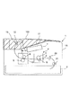
図1は、本発明の実施の形態に係るシート排出装置を備えた画像形成装置の一例であるレーザビームプリンタの概略構成を示す図である。このレーザビームプリンタ1は、レーザビームプリンタ本体(以下、プリンタ本体という)1Aと、画像形成部4と、画像形成部4に記録紙等のシートを給送するシート給送部2等を備えている。
FIG. 1 is a diagram showing a schematic configuration of a laser beam printer which is an example of an image forming apparatus provided with a sheet discharging apparatus according to an embodiment of the present invention. The laser beam printer 1 includes a laser beam printer main body (hereinafter referred to as a printer main body) 1A, an
ここで、画像形成部4は、感光体ドラム3と、感光体ドラム3の表面を露光して感光体ドラム3上に静電潜像を形成するレーザスキャナ7等を備えている。また、シート給送部2はシートを収納する不図示の給紙カセット及び給紙カセットに収納されたシートを1枚ずつ給送する不図示の給送ローラを備えている。
Here, the
なお、図1において、6は感光ドラム3に圧接しており感光ドラム3上に形成されたトナー像をシートに転写させるための転写ローラ5を有する転写部である。10は内部にヒータ8aを内蔵した加熱ローラ8と加熱ローラ8に圧接する加圧ローラ9とで形成されるニップを通過する際に転写画像の定着を行う定着部である。
In FIG. 1,
13は、プリンタ本体1Aの上面に設けられたシート積載部11と、定着後のシートをシート積載部11に排出するためのシート排出手段である1対のシート排出ローラ対12を備えたシート排出装置である。
A
このように構成されたレーザビームプリンタ1において、不図示のパソコン等から画像情報が送られると、不図示の給送ローラ、搬送ローラ対21及びレジストローラ22によってシートSが一枚ずつ搬送される。また、これと同期してレーザスキャナ7からの画像露光光により感光体ドラム3に潜像が形成される。
In the laser beam printer 1 configured as described above, when image information is sent from a personal computer (not shown), the sheet S is conveyed one by one by a feeding roller, a
次に、感光体ドラム上の潜像が不図示の現像装置によりトナーによって現像され、これにより感光体ドラム上にトナー画像が形成される。この後、このトナー画像が転写部6において転写ローラ5によってシートに転写され、このようにトナー画像が転写されたシートは、定着部10に搬送される。
Next, the latent image on the photosensitive drum is developed with toner by a developing device (not shown), thereby forming a toner image on the photosensitive drum. Thereafter, the toner image is transferred onto the sheet by the
そして、この定着部10において、加熱ローラ8と加圧ローラ9とにより加圧及び加熱されることにより、トナー画像がシート上に定着される。この後、画像が定着されたシートは、シート排出装置13に設けられた1対のシート排出ローラ対12によってシート排出口14からシート積載部11に排出される。
In the fixing
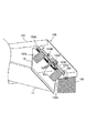
ところで、図1において、100はシート排出装置13に設けられた上面カバーユニットである。この上面カバーユニット100は、図2に示すように上面カバー101と、上面カバー101の裏側に設けられ、シート排出(搬送)方向に回動可能に支持されると共に非導電性の樹脂材料で形成されたシート押さえフラグ102a,102bを備えている。なお、図2において、102dは、シート押さえフラグ102a,102bが取り付けられた軸であり、シート押さえフラグ102a,102bは、この軸102dを介して上面カバー101に回動自在に保持されている。
In FIG. 1,
また、この上面カバーユニット100は、シート排出口14の上縁部に設けられた第2除電テープ103A、第3除電テープ103B、及び第2及び第3除電テープ103A,103Bをアースするための接地部材であるアース板金104を備えている。そして、アース板金104をプリンタ本体側板105に取り付けることで、第2及び第3除電テープ103A,103Bに対してアースをとることができる。
Further, the upper
ここで、シート押さえ部材であるシート押さえフラグ102a,102bは、シート積載部11に排出積載されている不図示のシートの後端付近を上方から押圧するためのものである。そして、このようにシート押さえフラグ102a,102bによってシートの後端付近を上方から押圧することにより、シートのカール等による浮きを押さえることができる。
Here, the
また、シート押さえフラグ102a,102bは、排出されるシートに押圧されて上方回動可能となっているため、仕様に則した積載枚数で満載の検知をすることも可能である。なお、本実施の形態においては、小サイズシートの満載が検知できるようにシート搬送中心部にも、他のシート押さえフラグ102cを設けている。
Further, since the
これにより、図3に示すように、定着後のシートSはシート押さえフラグ102a〜102cの底面に当接してシート押さえフラグ102a〜102cを上方回動させながら、シート排出ローラ対12によりシート積載部11に向かって排出される。
Thus, as shown in FIG. 3, the sheet S after fixing is brought into contact with the bottom surface of the
また、第2及び第3除電テープ103A,103B及び後述する第1除電テープ103Cは、非接触で除電が可能なものであり、例えば導電性ポリマーに被覆された繊維により構成されている不織布の空隙に粘着材を付与した構成のものである。
Further, the second and third
ここで、第3除電部材である第3除電テープ103Bは、シート積載部11に排出される前に、予めシートSに蓄積された静電気を非接触により除電するものである。この第3除電テープ103Bは図4に示すように、シート排出口14の内側に、排出されるシートSとの隙間が約5mmとなるように取り付けられている。
Here, the third static elimination tape 103 </ b> B as the third static elimination member neutralizes static electricity accumulated in advance on the sheets S before being discharged to the
また、第2除電部材である第2除電テープ103Aは、シート押さえフラグ102a,102bがシートに押圧されて上方回動した際、後述するシート押さえフラグ102a,102bに設けられた第1除電テープ103Cが近接する位置に設けられている。なお、本実施の形態において、第2除電テープ103Aは、図5に示すようにシート排出口14の内側の第3除電テープ103Bよりもシート排出方向下流側の、シート押さえフラグ102a,102bの近傍に取り付けられている。
In addition, the second
ところで、シート押さえフラグ102a,102bの底面により構成されるシート搬送面と反対側の外面には、図6に示すように第1除電部材である第1除電テープ103Cがシート搬送中心側にそれぞれ貼り付けられている。
By the way, on the outer surface opposite to the sheet conveyance surface constituted by the bottom surfaces of the
そして、シートSが排出される際、シート押さえフラグ102a〜102cがシートSに押圧され、図5の破線で示すシート押付位置から上方回動すると、この間、第1除電テープ103Cが第2除電テープ103Aに接近する。
When the sheet S is discharged, the
これにより、排出時、シートSがシート押さえフラグ102a〜102cに摺擦することでシートSに発生する静電気が、第1除電テープ103Cを介して、アース板金104に取り付けられている第2除電テープ103Aにより除電される。
As a result, the second static elimination tape attached to the
なお、第1除電テープ103Cが接近した際、第2除電テープ103Aと干渉して第1及び第2除電テープ103A,103Cの磨耗や剥がれが発生するのを防ぐため、第1除電テープ103Cと第2除電テープ103Aも非接触で、隙間は約5mmとなっている。
Incidentally, when the first
ここで、既述した図6に示したように、第1除電テープ103Cは、シート押さえフラグ102a,102bのシート搬送中心側に貼り付けられている。このため、排出してきたシートSの除電を行うと共に、シート押さえフラグ102a,102b自身に帯電した静電気も除電することもできる。
Here, as shown in FIG. 6 described above, the first
このように、本実施の形態においては、シート排出時、シートS及びシートSとの摩擦でシート押さえフラグ自身に帯電した静電気を、第1除電テープ103Cから近傍に貼り付けている第2除電テープ103Aに放電してアースを取っている。
As described above, in the present embodiment, when the sheet is discharged, the second static elimination tape in which the static electricity charged on the sheet pressing flag itself due to friction with the sheet S and the sheet S is pasted to the vicinity from the first
つまり、排出シートによりシート押さえフラグ102a〜102cが上方回動した際、第1除電テープ103Cを第2除電テープ103Aに近接させることにより、シート排出時、シートに発生した静電気を第2除電テープ103Aに放電するようにしている。
In other words, when the
そして、このように構成することにより、シート押さえフラグ102a〜102cとの摩擦でシートに発生した静電気を、第1除電テープ103Cの自己放電のみに頼るのではなく、シートが排出される都度、放電することができる。これにより、連続した画像形成動作によるシート押さえフラグ102a〜102cの帯電量の増加や、時間の経過に関わらず、安定してシートを除電して排出させることができる。
With this configuration, the static electricity generated in the sheet due to friction with the
なお、本実施の形態においては、第1〜第3除電テープ103A〜103Cを同一形状としており、これにより第1〜第3除電テープ103A〜103Cを間違って貼り付けることが無いため、組立てミスを防ぐことができる。この結果、製造コストや管理費等が抑えられるため、コストを安くすることができる。
In the present embodiment, the first to third
また、シート押さえフラグ102a〜102cには導電性の樹脂を使用しないため、シート押さえフラグ自身にアース機構を設ける必要がなく、簡素でコストの安いシート排出装置13を実現することができる。さらに、除電部材として除電テープを採用しているためコストが安く、除電テープをシート押さえフラグ102a,102bに貼り付けるだけで組み付けられるので、良好な組立て性能を確保することができる。
Further, since no conductive resin is used for the
なお、これまでの説明においては、画像形成後のシートをそのままシート積載部11に排出するようにしたレーザビームプリンタ1について説明した。しかし、本発明は、これに限られるものではない。
In the above description, the laser beam printer 1 is described in which the sheet after image formation is discharged to the
例えば、シートの両面に画像を形成することが可能な画像形成装置にも適用することができる。ここで、このような画像形成装置において、片面に画像が形成されたシートの裏面に画像を形成する場合、一旦シートの一部をシート積載部11に排出した後、再度装置本体内部に搬送するように構成されている。
For example, the present invention can be applied to an image forming apparatus capable of forming images on both sides of a sheet. Here, in such an image forming apparatus, when an image is formed on the back surface of a sheet on which an image is formed on one side, a part of the sheet is once discharged to the
しかし、このような構成の場合でも、本発明のように第1及び第2除電部材(第1及び第2除電テープ103A,103C)を接触させないようにすることにより、除電部材同士が磨耗したり剥がれたりするのを防ぐことができる。これにより、除電部材がシートに付いたまま、画像形成装置の内部に入り、画像不良やショートを起こすという問題の発生を防ぐことができる。
However, even in such a configuration, the first and second static elimination members (first and second
1 レーザビームプリンタ
4 画像形成部
11 シート積載部
12 シート排出ローラ対
13 シート排出装置
14 シート排出口
100 上面カバーユニット
101 上面カバー
102a〜102c シート押さえフラグ
103A 第2除電テープ
103B 第3除電テープ
103C 第1除電テープ
104 アース板金
S シート
DESCRIPTION OF SYMBOLS 1
Claims (6)
前記シート積載部に排出されたシートを上方から押圧すると共に、排出されるシートに押圧されて上方回動する非導電性のシート押さえ部材と、
前記シート押さえ部材に設けられ、シートが前記シート押さえ部材を押圧する際、シートに発生した静電気を除電する第1除電部材と、
前記シート押さえ部材がシートに押圧されて上方回動した際、前記第1除電部材が近接する第2除電部材と、
前記第2除電部材をアースする接地部材と、
を備え、
シートが前記シート押さえ部材を上方回動させながら排出される際、シートに発生した静電気を、前記接地部材によりアースされた前記第2除電部材に近接した前記第1除電部材から前記第2除電部材に放電することを特徴とするシート排出装置。 In a sheet discharge apparatus comprising: a sheet discharge unit that discharges a sheet; and a sheet stacking unit on which the sheets discharged by the sheet discharge unit are stacked.
A non-conductive sheet pressing member that presses the sheet discharged to the sheet stacking unit from above and is rotated by being pressed by the discharged sheet;
A first static elimination member that is provided in the sheet pressing member and neutralizes static electricity generated in the sheet when the sheet presses the sheet pressing member;
When pre-Symbol sheet pressing member is rotated upward by being pressed into a sheet, and a second charge removing member, wherein the first charge removing member is close,
A grounding member for grounding the second static elimination member;
With
When the sheet is discharged while rotating the sheet pressing member upward, the second static eliminator from the first static eliminator close to the second static eliminator that is grounded by the ground member A sheet discharging apparatus that discharges to the surface.
前記第3除電部材を前記接地部材によりアースすることを特徴とする請求項1又は2記載のシート排出装置。 A third static elimination member that neutralizes static electricity accumulated in the sheet before the sheet is discharged to the sheet stacking unit;
The sheet discharging apparatus according to claim 1 or 2, wherein the third static elimination member is grounded by the grounding member.
Priority Applications (1)
| Application Number | Priority Date | Filing Date | Title |
|---|---|---|---|
| JP2006307268A JP4773927B2 (en) | 2006-11-13 | 2006-11-13 | Sheet discharging apparatus and image forming apparatus |
Applications Claiming Priority (1)
| Application Number | Priority Date | Filing Date | Title |
|---|---|---|---|
| JP2006307268A JP4773927B2 (en) | 2006-11-13 | 2006-11-13 | Sheet discharging apparatus and image forming apparatus |
Publications (3)
| Publication Number | Publication Date |
|---|---|
| JP2008120531A JP2008120531A (en) | 2008-05-29 |
| JP2008120531A5 JP2008120531A5 (en) | 2010-01-07 |
| JP4773927B2 true JP4773927B2 (en) | 2011-09-14 |
Family
ID=39505711
Family Applications (1)
| Application Number | Title | Priority Date | Filing Date |
|---|---|---|---|
| JP2006307268A Expired - Fee Related JP4773927B2 (en) | 2006-11-13 | 2006-11-13 | Sheet discharging apparatus and image forming apparatus |
Country Status (1)
| Country | Link |
|---|---|
| JP (1) | JP4773927B2 (en) |
Families Citing this family (2)
| Publication number | Priority date | Publication date | Assignee | Title |
|---|---|---|---|---|
| JP5159545B2 (en) * | 2008-10-01 | 2013-03-06 | キヤノン株式会社 | Image forming apparatus |
| JP6896697B2 (en) | 2018-12-27 | 2021-06-30 | キヤノン株式会社 | Sheet ejection device and image forming device |
-
2006
- 2006-11-13 JP JP2006307268A patent/JP4773927B2/en not_active Expired - Fee Related
Also Published As
| Publication number | Publication date |
|---|---|
| JP2008120531A (en) | 2008-05-29 |
Similar Documents
| Publication | Publication Date | Title |
|---|---|---|
| JP4715929B2 (en) | Image forming apparatus and sheet conveying apparatus | |
| JP5198515B2 (en) | Image forming apparatus | |
| US7424257B2 (en) | Paper guide device and image forming apparatus having the same | |
| KR100880474B1 (en) | Image forming apparatus | |
| JP5006982B2 (en) | Fixing device and image forming apparatus including the fixing device | |
| JP4946390B2 (en) | Image forming apparatus | |
| JP2005096965A (en) | Paper delivery device and image forming device | |
| US11199801B2 (en) | Sheet discharging apparatus having electrostatic charge removal and image forming apparatus | |
| JP4702438B2 (en) | Image forming apparatus | |
| JP4852000B2 (en) | Fixing device and image forming apparatus including the fixing device | |
| JP4773927B2 (en) | Sheet discharging apparatus and image forming apparatus | |
| JP5001675B2 (en) | Conveyance guide and image forming apparatus | |
| JP5910225B2 (en) | Fixing device and image forming apparatus | |
| US20220244672A1 (en) | Image forming apparatus | |
| JP2011033761A (en) | Image forming apparatus | |
| US6178307B1 (en) | Attraction member and image forming apparatus using the same | |
| JP4074025B2 (en) | Image forming apparatus | |
| JP5090982B2 (en) | Image forming apparatus | |
| JP6435836B2 (en) | Conveying guide member, transfer device, and image forming apparatus | |
| JP6245162B2 (en) | Fixing apparatus and image forming apparatus | |
| JP5294070B2 (en) | Fixing apparatus and image forming apparatus | |
| CN111338188B (en) | Image forming apparatus | |
| JP5786377B2 (en) | Transfer device, image forming device | |
| JP2009122448A (en) | Paper discharging device and image forming apparatus provided with same | |
| JP2006145639A (en) | Image forming apparatus |
Legal Events
| Date | Code | Title | Description |
|---|---|---|---|
| A521 | Written amendment |
Free format text: JAPANESE INTERMEDIATE CODE: A523 Effective date: 20091113 |
|
| A621 | Written request for application examination |
Free format text: JAPANESE INTERMEDIATE CODE: A621 Effective date: 20091113 |
|
| A977 | Report on retrieval |
Free format text: JAPANESE INTERMEDIATE CODE: A971007 Effective date: 20110601 |
|
| TRDD | Decision of grant or rejection written | ||
| A01 | Written decision to grant a patent or to grant a registration (utility model) |
Free format text: JAPANESE INTERMEDIATE CODE: A01 Effective date: 20110621 |
|
| A01 | Written decision to grant a patent or to grant a registration (utility model) |
Free format text: JAPANESE INTERMEDIATE CODE: A01 |
|
| A61 | First payment of annual fees (during grant procedure) |
Free format text: JAPANESE INTERMEDIATE CODE: A61 Effective date: 20110624 |
|
| FPAY | Renewal fee payment (event date is renewal date of database) |
Free format text: PAYMENT UNTIL: 20140701 Year of fee payment: 3 |
|
| R150 | Certificate of patent or registration of utility model |
Free format text: JAPANESE INTERMEDIATE CODE: R150 |
|
| LAPS | Cancellation because of no payment of annual fees |