JP4772736B2 - Pipe tip processing tool - Google Patents
Pipe tip processing tool Download PDFInfo
- Publication number
- JP4772736B2 JP4772736B2 JP2007111741A JP2007111741A JP4772736B2 JP 4772736 B2 JP4772736 B2 JP 4772736B2 JP 2007111741 A JP2007111741 A JP 2007111741A JP 2007111741 A JP2007111741 A JP 2007111741A JP 4772736 B2 JP4772736 B2 JP 4772736B2
- Authority
- JP
- Japan
- Prior art keywords
- pipe
- shaft portion
- tip
- insertion shaft
- diameter
- Prior art date
- Legal status (The legal status is an assumption and is not a legal conclusion. Google has not performed a legal analysis and makes no representation as to the accuracy of the status listed.)
- Active
Links
Images


Landscapes
- Turning (AREA)
Description
本発明は、パイプ先端加工具に関する。 The present invention relates to a pipe tip processing tool.
パイプの配管施工の際に、パイプを継手等に挿入する作業では、挿入作業が容易になるように、パイプの内周角部へ面取り作業をおこなっていた。また、密封性が必要とされる配管継手等には、パイプとの接触部にOリング等のシール部材を備えているため、シール部材の損傷を防ぐためにも、パイプ内周角部を面取り状とする必要があった。
そこで、従来の、パイプ先端を面取り状に加工する工具は、刃部を備え、その刃部をパイプに挿入し、パイプの内周角部に当接させ、押し込みながら回転させることで、パイプの内端縁を切削加工で面取りするものであった。(例えば、特許文献1参照)。
Therefore, a conventional tool for processing the tip of a pipe into a chamfered shape includes a blade portion, and the blade portion is inserted into the pipe, brought into contact with an inner peripheral corner portion of the pipe, and rotated while being pushed in, thereby rotating the pipe. The inner edge was chamfered by cutting. (For example, refer to Patent Document 1).
しかし、従来の加工具では、面取り作業を確実におこなっても、パイプ自体の寸法誤差や、真円度のばらつきが原因で、パイプの挿入が困難であったり、シール部材を損傷させてしまう等の不具合には対応できなかった。また、面取り作業の際に切屑が発生し、パイプ内部へ切屑が侵入しないように作業をおこなう必要があった。さらに、作業後に切屑の除去や清掃作業が必要であった。 However, with the conventional processing tool, even if the chamfering work is performed reliably, it is difficult to insert the pipe or damage the seal member due to dimensional error of the pipe itself and variation in roundness. It was not possible to cope with the problem. In addition, it is necessary to perform work so that chips are generated during the chamfering work and do not enter the pipe. Furthermore, it was necessary to remove chips and clean up after the work.
特に、パイプの壁部を3層に構成して、内径側の層を樹脂とし、中間層を金属として、外径側の層を樹脂とした、給水・給湯の配管に用いられる金属・プラスチック複合管(又は、金属強化樹脂管とも言う)では、切断作業の際に、パイプの管端面(切断面)が変形し、面取り作業をおこなっても、継手への挿入が困難な場合が多かった。さらに、無理に挿入するとシール部材を損傷し、漏れの原因となっていた。そのため、変形したパイプの先端部を挿入前に修正する必要があった。 In particular, the pipe wall is composed of three layers, the inner layer is made of resin, the intermediate layer is made of metal, and the outer diameter side is made of resin. In the case of a pipe (or metal reinforced resin pipe), the pipe end face (cut surface) of the pipe is deformed during the cutting operation, and even when the chamfering operation is performed, it is often difficult to insert into the joint. Furthermore, if it is forcibly inserted, the seal member is damaged, causing leakage. Therefore, it is necessary to correct the tip of the deformed pipe before insertion.
そこで、本発明は、主として、金属・プラスチック複合管(金属強化樹脂管)の内周角部を確実に面取り状にすると共に切屑を出さず、さらに、継手等への挿入に適した加工をすることができるパイプ先端加工具の提供を目的とする。 Therefore, the present invention mainly makes the inner peripheral corner of the metal / plastic composite pipe (metal reinforced resin pipe) chamfered reliably, does not produce chips, and performs processing suitable for insertion into a joint or the like. An object of the present invention is to provide a pipe tip processing tool.
そこで、本発明に係るパイプ先端加工具は、先端縮径テーパ部を有して被加工用パイプに挿入して塑性変形によって該パイプの内径を拡大して真円状に矯正するための拡径変形用挿入軸部と、該挿入軸部の基端に形成される外鍔部と、を、備え、かつ、該挿入軸部の基端と上記外鍔部の先端面の隅部に、上記挿入軸部の円周方向の回転にて上記パイプの最先端の内周角部を圧潰して面取り状とするための圧潰用突起部を2つ有し、上記外鍔部の上記先端面に、上記パイプの上記最先端の外周面に摺接して、上記突起部によって上記最先端が拡径方向へ逃げるのを抑制するための、上記挿入軸部の円周方向に沿った円弧状の外周面抑圧片を突出状に2つ配設し、上記外周面抑圧片を、上記挿入軸部を挟んで対面状に設け、該挿入軸部の軸心方向から見て、上記外周面抑圧片を上記突起部に対して上記挿入軸部の円周方向に位置をずらして配設し、さらに、上記挿入軸部に、平面をもって形成した逃がし部を複数設け、各々異なる内径の被加工パイプに、夫々、対応する3本乃至4本の上記挿入軸部を、放射枝状に配設して成ると共に、上記挿入軸部の各々に、上記外鍔部と上記突起部と上記外周面抑圧片とを、配設したものである。
Therefore, the pipe tip processing tool according to the present invention has a tip diameter-reduced taper portion, and is inserted into a pipe to be processed to expand the inner diameter of the pipe by plastic deformation and correct it into a perfect circle. An insertion shaft portion for deformation and an outer flange portion formed at the proximal end of the insertion shaft portion, and the base end of the insertion shaft portion and the corner of the distal end surface of the outer flange portion, There are two crushing projections for chamfering the innermost corner of the pipe by rotating the insertion shaft in the circumferential direction, and on the tip surface of the outer collar , in sliding contact with the outer peripheral surface of the leading edge of the pipe, for suppressing the above cutting-edge escape the diameter direction by the protruding portions, arcuate periphery along the circumferential direction of the insertion shaft portion and two disposed surfaces suppression pieces protrude, the outer peripheral surface suppression piece, arranged in facing shape by sandwiching the insertion shaft portion, the axial direction of the insertion shaft portion Look al, the outer peripheral surface suppression pieces arranged by shifting the positions in the circumferential direction of the insertion shaft portion relative to the projections, furthermore, to the insertion shaft portion, a plurality of relief portions formed with
本発明のパイプ先端加工具によれば、被加工用パイプに挿入して塑性変形によってパイプの内径を拡大する拡径変形用挿入軸部を備えているので、真円に矯正しつつパイプの内径を所定の寸法にすることができる。また、パイプの最先端の内周角部を圧潰して面取り状とするための圧潰用突起部を有するので、確実にパイプの最先端の内周角部を面取り状にできる。さらに圧潰するので、切削加工に比べて切屑が発生しない。また、パイプの最先端の外周面に摺接して突起部によって最先端が拡径方向へ逃げるのを抑制する外周面抑圧片を備えているので、パイプ最先端の外径寸法が増大するのを防止できる。また、外周面抑圧片を複数個配設しているので、より確実に最先端が拡径方向へ逃げるのを抑制できる。また、3本乃至4本の上記挿入軸部を、放射枝状に配設しているので、様々なパイプに対応できる。また、使用しない軸部を持ち手として回転トルクを付与しやすい。 According to the pipe tip processing tool of the present invention, since it has the insertion shaft portion for expanding and deforming which is inserted into the pipe to be processed and expands the inner diameter of the pipe by plastic deformation, the inner diameter of the pipe is corrected to a perfect circle. Can be of a predetermined dimension. Moreover, since the crushing protrusion for crushing the chamfered inner peripheral corner portion of the pipe into a chamfered shape is provided, the chamfered inner peripheral corner portion of the pipe can be surely formed. Furthermore, since crushing, chips are not generated as compared with cutting. In addition, since the outer peripheral surface suppression piece that slides into contact with the outermost peripheral surface of the pipe and suppresses the distal end from escaping in the diameter-expanding direction by the protrusion, the outer diameter of the distal end of the pipe is increased. Can be prevented. In addition, since a plurality of outer peripheral surface suppression pieces are arranged, it is possible to more reliably prevent the leading edge from escaping in the diameter expansion direction. Further, since the three to four insertion shaft portions are arranged in a radial branch shape, various pipes can be handled. Moreover, it is easy to give rotational torque by using a shaft portion that is not used as a handle.
以下、実施の形態及び参考例を示す図面に基づき本発明を詳説する。
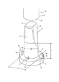
図1は本発明に関係の深いパイプ先端加工具の第1参考例と被加工パイプの斜視図である。また、図2は、その要部拡大説明図である。また、図3は、使用状態を示す断面図であり、(a)は、その一部平面断面図であり、(b)は、そのA−A側面断面図である。
10は、本発明に係るパイプ先端加工具の使用の主たる対象となる被加工用パイプである。被加工用パイプ10は、給水・給湯の配管に用いられる金属・プラスチック複合管(又は、金属強化樹脂管と言う)であって、壁部を3層から構成している。内径側に樹脂の第1層13を、外径側に樹脂の第3層15を有し、第1層13と第3層15の間に薄い金属の第2層14を有する。
Hereinafter, the present invention will be described in detail with reference to the drawings showing embodiments and reference examples.
FIG. 1 is a perspective view of a first reference example of a pipe tip processing tool and a pipe to be processed, which are closely related to the present invention. FIG. 2 is an enlarged explanatory view of the main part. FIG. 3 is a sectional view showing a use state, (a) is a partial plan sectional view, and (b) is an AA side sectional view.
2は、被加工用パイプ10が継手等に挿入し易い理想の内径寸法に拡径させるための外径寸法(D)を有する軸部であって、軸部2は、基端から所定の長さ(H寸法)にパイプ挿入方向(先端方向)へD寸法のストレート部6を形成している。さらに、パイプ挿入方向(先端)部に向かって縮径するテーパ部1を有している。また、軸部2に平面を形成した逃がし部8を180°反対位置に2箇所設けている。また、軸部2の外径寸法Dについては、被加工用パイプ10の端面16が切断や生産時の精度等の理由により変形(偏平)しているので、被加工用パイプ10の(平均)内径寸法dよりも僅かに大きく設定する。また図2に於て、Dtは、本発明に係るパイプ先端加工具で加工する前の変形したパイプ10の(平均)外径寸法を示している。
そして、軸部2の基端には、被加工用パイプ10の外径よりも大きい外鍔部5を形成している。さらに、軸部2の基端には、被加工用パイプ10に軸部2を挿入して、パイプ10の端面16が外鍔部5の先端面5aを当接した際に、パイプ10の最先端11の内周角部12を圧潰して面取り状に成形可能な圧潰用突起部3を有している。この突起部3は、図3(b)のA−A断面図に示すように軸部2と外鍔部5の隅部に一体形成され、傾斜状の圧接面3aを有している。
An
さらに、軸部2をパイプ10に挿入して、端面16を外鍔部5の先端面5aに当接させた際に、パイプ10の拡径方向の逃げ(変形)を抑制する外周面抑圧片4を備えている。この抑圧片4は、外鍔部5の先端面5aから先端方向(パイプへの挿入方向)へ突出して設けている。また、軸部2を挟んで対面状に2箇所設けている。また、この抑圧片4の軸部2と対面する抑圧面4aは先端面5aから所定の高さにストレート部を形成した後に先端部に向かって曲面勾配部を形成している。さらに、抑圧面4aと抑圧片4の円周方向の側面4bとの角部を曲面状に面取り形成している。また、向かい合う抑圧面4a,4aの対面距離寸法は、パイプ10が継手等に挿入するのに適した外径寸法の近傍(又は、等しい)値であるT寸法に設定している。
Further, when the
次に図5は、第2参考例を示す斜視図である。まず、第1参考例と同様のテーパ部1を有する軸部2の基端に突起部3と外鍔部5を形成し、抑圧片4を外鍔部5から突出して設けている。そして、この軸部2を3つ設けている。さらに、3つの軸部2,2,2の先端が向かい合わないようにY字状(放射枝状)に配設している。また、各々の外鍔部5,5,5の裏面5b,5b,5bから円柱状の連結軸部7,7,7を突出して設け、Y字の交点で集合させて一体状に結合している。言いかえれば、Y字状の円柱体の各々(3箇所の)端部に軸部2を突出して設けた形状と言える。
Next, FIG. 5 is a perspective view showing a second reference example . First, the
ここで、3つの軸部2,2,2は、各々異なる径の被加工用パイプ10に対応している。つまり、3つの軸部2,2,2のストレート部6,6,6の直径寸法Dは各々異なっている。さらに、各々の軸部2,2,2の抑圧面4aの対面距離のT寸法は、各々異なる径の被加工用パイプ10の継手等の挿入に適した外径に対応するように設定されている。
Here, the three
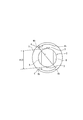
第3参考例は、図6のように、突起部3と抑圧片4を対面状(同一の周方向の位置)に設け、抑圧片4を円周方向に沿った円弧状に設けている。
第4参考例は、図7と図8に示すように突起部3と抑圧片4は、各軸部2の軸心方向から見て、突起部3と抑圧片4を約5°〜45°、好ましくは10°〜30°の中心角度差をもって、配設するのが良い。このように突起部3に対して抑圧片4の配設位置をずらせることにより、適切なラジアル内方向への抑圧力を抑圧片4が被加工用パイプ10の外周面に付与することができて、美しく面取り状に内周角部を圧潰できる。さらに、図7や図8のように、突起部3の形状は、図1〜図6のものよりも、丸み(アール)を付与した丸山型断面形状としている。また、軸部2の先端の面取りを2段として、パイプ10への挿入を容易としている。
次に、本発明の実施の形態は、図9と図10のように、突起部3と抑圧片4の一方の(突起部3近傍側の)側壁面4bを約0°〜30°、好ましくは2°〜10°の中心角度差をもって、配設するのが良い。このように突起部3に対して抑圧片4の配設位置をずらせることにより、適切なラジアル内方向への抑圧力を抑圧片4が被加工用パイプ10の外周面に付与することができて、美しく面取り状に内周角部を圧潰できる。さらに、図9や図10のように、軸部2の逃がし部8を4箇所形成して、パイプ10への挿入を容易としている。
また、突起部3の圧接面3aを斜面ではなく凹曲面状に形成して、パイプ10の内周角部12をR曲面状に圧潰しても良い。また、軸部2の基端に操作用のハンドル部を設けても良い。また、図示省略するが、異なる径の被加工パイプ10に各々対応した4つの軸部2,2,2,2の外鍔部5,5,5,5の裏面5b,5b,5b,5bに連結軸部7,7,7,7を設け、連結軸部7,7,7,7を十字状(放射枝状)に一体結合して形成しても良い。(言い換えれば、十字状の円柱体の各々(4箇所の)端部に軸部2を突出して設けた形状としても良い。)
The third reference example, as shown in FIG. 6, provided with a
In the fourth reference example, as shown in FIGS. 7 and 8, the
Next , in the embodiment of the present invention, as shown in FIGS. 9 and 10, the
Alternatively, the
上述した本発明に係るパイプ先端加工具の実施の形態の使用方法(作用)について説明する。
まず、給湯・給水配管施工の際に、被加工パイプ10を切断する。すると、パイプ10の端面16(切断面)は、切断による力を受けて変形して、真円でなくなる。そのため、パイプの内径を継手等への挿入に適した形状及び寸法にする必要がある。また、継手等に挿入するためにパイプ10の内周角部12を面取り状にする必要がある。
The usage method (action) of the above-described embodiment of the pipe tip processing tool according to the present invention will be described.
First, the
そこで、パイプ10の端面16に外鍔部5の先端面5aが当接するまで軸部2を回転させながら挿入してパイプ10の最先端11を加工する。まず、軸部2のテーパ部1に沿ってストレート部6の手前までパイプ10に挿入する。ストレート部6からは、軸部2を円周方向の一定方向に回転させながら捩じり込むように挿入していく。すると、パイプ10の最先端11の内径は、軸部2によって、拡径方向に軸部2の外径寸法であるD寸法に塑性変形されると共に、形状も真円状に塑性変形され、パイプ10の外周面が突起部3の先端部に沿って抑圧面4aに摺接される。抑圧片4は、パイプ10の外径寸法が抑圧面4aの対面距離寸法のT寸法より大きくならないように拡径方向への塑性変形を抑制すると共に、外径の形状が極端な偏平や拡径とならないように抑制する。次に、圧潰用突起部3の圧接面3aにパイプ10の内周角部12が接触した後、圧潰用突起部3がパイプ10の最先端11の内周角部12を圧潰して、内周角部12を面取り状に形成する。内周角部12が圧潰されることで、パイプ10の外径(外周面)は拡径方向の力を受けるが、抑圧片4によって、拡径方向の逃げを抑制すると共に、外径が抑圧片4の対面距離寸法のT寸法より大きくなることを抑制し、継手等の挿入に不適切な形状に変形するのを抑制する。そして、パイプ10の端面16に外鍔部5の先端面5aを当接させる。端面16を先端面5aに当接させた状態で円周方向に1回転させると、確実にパイプ10の最先端11の内周角部12が円周に沿って面取り状となる。以上で加工が終了する。
Therefore, the
また、他の使用手順として、軸部2を、パイプ10の端面16が外鍔部5の先端面5aに当接するまで挿入し、その後、軸部2の円周方向の一定方向に1回転させる手順でも良い。この際、パイプ10は、パイプ内径が拡径方向に軸部2の外径寸法Dに塑性変形し、パイプ10の最先端11の外径(外周面)は抑圧片4の対面距離寸法のT寸法以内に抑制されると共に、継手等に適切な形状に抑制される。さらに、パイプ10の最先端11の内周角部12は突起部3によって圧潰されて面取り状に形成される。つまり、パイプ10は上述したどちらの使用手順であっても同様の形状に加工される。
As another use procedure, the
ここで、加工後の被加工用パイプ10の要部拡大断面図を図4に示す。
図4に於て、パイプ最先端11の内径は、端面16から軸部2のストレート部6の長さであるH寸法だけ、軸部2の外径寸法と同様のD寸法に塑性変形されている。そして、パイプ10の最先端11の外径寸法は、抑圧片4の対面距離寸法と同様のT寸法に抑制され、形状も、継手の挿入に適した(極端な偏平や縮径・拡径でない)形状となっている。さらに、パイプ10の最先端11の内周角部12は面取り状に圧潰(塑性変形)されている。
Here, the principal part expanded sectional view of the
In FIG. 4, the inner diameter of the
次に、実施の形態では、軸部2を3つ備えており、それぞれの軸部2,2,2が異なる被加工用パイプ10に対応しているので、配管施工する被加工パイプ10と対応する継手等に適した加工が可能なものを選択し、施工に適した軸部2を被加工パイプ10に挿入する。そして、軸部2を回転させる際に、挿入していない残りの軸部2,2や、外鍔部5の裏面5bから突設させた連結軸部7,7を回転用操作ハンドルとして使用する。そして、パイプ10の端面16を外鍔部5の先端面5aに当接するまで、軸部2をパイプ10に挿入させながら回転させる(又は、外鍔部5の先端面5aにパイプ10の端面16が当接するまで挿入してから回転させる)。すると、パイプ10の最先端11の内周角部12が面取り状に形成されると共に、内径が継手挿入に適したD寸法に塑性変形されて、さらに、外径(外周面)は継手等の挿入に不適切な形状に変形するのを抑制されて、パイプ10は加工される。つまり、パイプ10を継手等の挿入に適切な形状に加工する。
Next, in the embodiment, three
以上のように、本発明は、先端縮径テーパ部1を有して被加工用パイプ10に挿入して塑性変形によってパイプ10の内径を拡大する拡径変形用挿入軸部2を、備え、かつ、挿入軸部2の基端には、パイプ10の最先端11の内周角部12を圧潰して面取り状とするための圧潰用突起部3を有するので、切屑発生させず内周角部12を面取り状にできる。また、切屑の除去作業や清掃作業が不要になり作業効率が向上する。また、拡径変形用挿入軸部2と圧潰用突起部3とを備えているので、パイプ10の内径の塑性加工と面取り(塑性)加工ができると共に、内径と外径の真円度が向上し、継手への挿入を容易におこなえる。また、継手等のシール部材とパイプ10の間に切屑が挟まることがないので、漏れの原因を解消できる。また、パイプ10の内径の塑性加工と面取り(塑性)加工とを一つの工具で可能なので、配管施工が迅速にできる。また、圧潰により内周角部12を面取り状とするので、切削加工に比べて鋭利なバリや傷等が面取り部に発生せず継手への挿入の際にシール部材(Oリングやパッキン等)を損傷させずに施工できる。
As described above, the present invention includes the
先端縮径テーパ部1を有して被加工用パイプ10に挿入して塑性変形によってパイプ10の内径を拡大する拡径変形用挿入軸部2を、備え、かつ、挿入軸部2の基端には、パイプ10の最先端11の内周角部12を圧潰して面取り状とするための圧潰用突起部3を有し、さらに、パイプ10の最先端11の外周面に摺接して突起部3によって最先端11が拡径方向へ逃げるのを抑制する外周面抑圧片4を、備えているので、パイプ10の内径の塑性加工と面取り(塑性)加工と、外周面の変形(逃げ)の抑制ができると共に、内径と外径の真円度が向上して、継手等への挿入を容易におこなえる。また、切屑発生させず内周角部12を面取り状にできる。また、切屑の除去作業や清掃作業が不要になり作業効率が向上する。また、継手等のシール部材とパイプ10の間に切屑が挟まることがないので、漏れの原因を解消できる。また、パイプ10の内径の塑性加工と面取り(塑性)加工と、外周面の変形の抑制を一つの工具で可能なので、配管施工が迅速にできる。また、圧潰により内周角部12を面取り状とするので、切削加工に比べて鋭利なバリや傷等が面取り部に発生せず継手への挿入の際にシール部材(Oリングやパッキン等)を損傷させず施工できる。また、パイプ10の外周面が継手等の挿入に不適切な(極端な偏平や拡径)形状になるのを防止できる。また、抑圧片4によって逃げを抑制するので、圧潰用突起部3にて確実にパイプ10の最先端11の内周角部12を面取り状にできる。また、外周に凹周溝とその凹周溝にシール材が嵌装されて内挿筒部を有する管継手の挿入に適した形状に加工することができる。
The
また、挿入軸部2の基端に外鍔部5を形成して、外鍔部5から突出状に外周面抑圧片4を複数個配設したので、確実に外周面の変形(逃げ)を防止できる。また、外鍔部5を回転させる際の握り部として使用できる。
また、3本乃至4本の挿入軸部2,2,2を、放射枝状に配設して成るので、異なる径の被加工パイプ10の加工を1つの工具で対応できる。また、使用しない軸部2,2を回転用の操作ハンドルとして使用できる。
In addition, since the
Further, since the three to four
1 テーパ部
2 軸部
3 突起部
4 抑圧片
5 外鍔部
5a 先端面
8 逃がし部
10 パイプ
11 最先端
12 内周角部
DESCRIPTION OF
10 pipes
11 cutting edge
12 Inner corner
Claims (1)
上記外鍔部(5)の上記先端面(5a)に、上記パイプ(10)の上記最先端(11)の外周面に摺接して、上記突起部(3)によって上記最先端(11)が拡径方向へ逃げるのを抑制するための、上記挿入軸部(2)の円周方向に沿った円弧状の外周面抑圧片(4)を突出状に2つ配設し、
上記外周面抑圧片(4)を、上記挿入軸部(2)を挟んで対面状に設け、該挿入軸部(2)の軸心方向から見て、上記外周面抑圧片(4)を上記突起部(3)に対して上記挿入軸部(2)の円周方向に位置をずらして配設し、
さらに、上記挿入軸部(2)に、平面をもって形成した逃がし部(8)を複数設け、
各々異なる内径の被加工パイプ(10)に、夫々、対応する3本乃至4本の上記挿入軸部(2)を、放射枝状に配設して成ると共に、上記挿入軸部(2)の各々に、上記外鍔部(5)と上記突起部(3)と上記外周面抑圧片(4)とを、配設したことを特徴とするパイプ先端加工具。 Insertion for expanding the diameter of the pipe (10) having a reduced diameter tapered portion (1) and inserting into the pipe (10) to be machined to enlarge the inner diameter of the pipe (10) by plastic deformation and correct it into a perfect circle. A shaft portion (2), and an outer flange portion (5) formed at a proximal end of the insertion shaft portion (2), and the proximal end of the insertion shaft portion (2) and the outer flange portion. The inner peripheral corner (12) of the tip (11) of the pipe (10) is crushed at the corner of the tip surface (5a) of (5) by the circumferential rotation of the insertion shaft (2). And have two crushing protrusions (3) for chamfering,
In the outer collar portion above the tip face of the (5) (5a), in sliding contact with the outer peripheral surface of the cutting edge (11) of the pipe (10), the protruding portions above advanced (11) by (3) Two arcuate outer circumferential surface suppression pieces (4) along the circumferential direction of the insertion shaft portion (2) for suppressing escape in the diameter-expanding direction are disposed in a projecting manner,
The outer circumferential surface suppression piece (4) is provided in a face-to-face manner with the insertion shaft portion (2) in between, and the outer circumferential surface suppression piece (4) is seen from the axial direction of the insertion shaft portion (2). Disposed in the circumferential direction of the insertion shaft (2) with respect to the protrusion (3),
Further, the insertion shaft portion (2) is provided with a plurality of relief portions (8) formed with a plane,
Three to four corresponding insertion shafts (2) corresponding to the pipes (10) having different inner diameters are arranged in a radial branch shape, and the insertion shafts (2) A pipe tip processing tool , wherein the outer flange (5), the protrusion (3), and the outer circumferential surface suppression piece (4) are disposed in each .
Priority Applications (1)
| Application Number | Priority Date | Filing Date | Title |
|---|---|---|---|
| JP2007111741A JP4772736B2 (en) | 2007-04-20 | 2007-04-20 | Pipe tip processing tool |
Applications Claiming Priority (1)
| Application Number | Priority Date | Filing Date | Title |
|---|---|---|---|
| JP2007111741A JP4772736B2 (en) | 2007-04-20 | 2007-04-20 | Pipe tip processing tool |
Publications (2)
| Publication Number | Publication Date |
|---|---|
| JP2008264835A JP2008264835A (en) | 2008-11-06 |
| JP4772736B2 true JP4772736B2 (en) | 2011-09-14 |
Family
ID=40045080
Family Applications (1)
| Application Number | Title | Priority Date | Filing Date |
|---|---|---|---|
| JP2007111741A Active JP4772736B2 (en) | 2007-04-20 | 2007-04-20 | Pipe tip processing tool |
Country Status (1)
| Country | Link |
|---|---|
| JP (1) | JP4772736B2 (en) |
Family Cites Families (8)
| Publication number | Priority date | Publication date | Assignee | Title |
|---|---|---|---|---|
| JPS5541221A (en) * | 1978-09-19 | 1980-03-24 | Toyo Electric Mfg Co Ltd | Automatic feeder of pencil lead |
| JPS6096336A (en) * | 1983-10-31 | 1985-05-29 | Nippon Steel Corp | Method for working end of double-layered heat insulating pipe |
| JPS60131223A (en) * | 1983-12-21 | 1985-07-12 | Fuji Heavy Ind Ltd | Expanding method of diameter of thermoplastic hose |
| JPS6292121A (en) * | 1985-10-17 | 1987-04-27 | Hitachi Maxell Ltd | Magnetic recording medium |
| JPS632602A (en) * | 1986-06-20 | 1988-01-07 | Toshiba Corp | Pipe end machining tool |
| JP3047502B2 (en) * | 1991-04-17 | 2000-05-29 | オイレス工業株式会社 | Bearing device and method of manufacturing the same |
| DE10056610A1 (en) * | 2000-11-15 | 2002-05-23 | Schuler Hydroforming Gmbh & Co | High-pressure bulge-forming apparatus for producing complex-shaped hollow articles, has fasteners that releasably secure heads on stems of actuators aligned with cavity ends of multipart die assembly |
| JP2003145347A (en) * | 2001-11-20 | 2003-05-20 | Sekisui Chem Co Ltd | Pipe end correcting jig |
-
2007
- 2007-04-20 JP JP2007111741A patent/JP4772736B2/en active Active
Also Published As
| Publication number | Publication date |
|---|---|
| JP2008264835A (en) | 2008-11-06 |
Similar Documents
| Publication | Publication Date | Title |
|---|---|---|
| JP4256899B2 (en) | Pipe fitting | |
| JP4776791B2 (en) | Double pipe end processing method | |
| WO2008118944A2 (en) | Sealing fitting for stainless steel tubing | |
| JP2010110791A (en) | Tool for friction stir welding, and method for joining two member by friction stir welding | |
| JP2009168075A (en) | Pipe joint structure, and pipe connection method | |
| JP4772736B2 (en) | Pipe tip processing tool | |
| JP2009142877A (en) | Tube end correcting tool | |
| JP4476263B2 (en) | Pipe fitting | |
| JP6976017B1 (en) | Pipe fitting structure | |
| JP2010094797A (en) | Tool for internal diameter correction and internal angle edge chamfering of pipe end | |
| JP2015124862A (en) | Pipe branch connection, branch pipe unit and process of manufacturing them | |
| JP2003145333A (en) | Port forming method and cutting tool to be used for the same | |
| US20040130148A1 (en) | Conventionally formed double O-ring coupling | |
| JP6924538B1 (en) | Pipe fitting structure | |
| JP4931579B2 (en) | Burr treatment method in friction welding | |
| JP2010221294A (en) | Tool for straightening pipe end | |
| JP4428621B2 (en) | Incore | |
| JP4935444B2 (en) | Bite type fittings, refrigeration equipment and hot water equipment | |
| JP7126209B2 (en) | pipe joint | |
| TW200905113A (en) | Flared coupling structure | |
| JP7185877B2 (en) | pipe joint | |
| JP2008075807A (en) | Joint and manufacturing method thereof | |
| JP6654801B2 (en) | Pipe fittings | |
| JP6901134B2 (en) | Pipe fitting structure | |
| JP4275245B2 (en) | Liquid-tight collet |
Legal Events
| Date | Code | Title | Description |
|---|---|---|---|
| A977 | Report on retrieval |
Free format text: JAPANESE INTERMEDIATE CODE: A971007 Effective date: 20100311 |
|
| A131 | Notification of reasons for refusal |
Free format text: JAPANESE INTERMEDIATE CODE: A131 Effective date: 20101130 |
|
| A521 | Request for written amendment filed |
Free format text: JAPANESE INTERMEDIATE CODE: A523 Effective date: 20101220 |
|
| A131 | Notification of reasons for refusal |
Free format text: JAPANESE INTERMEDIATE CODE: A131 Effective date: 20110301 |
|
| A521 | Request for written amendment filed |
Free format text: JAPANESE INTERMEDIATE CODE: A523 Effective date: 20110404 |
|
| TRDD | Decision of grant or rejection written | ||
| A01 | Written decision to grant a patent or to grant a registration (utility model) |
Free format text: JAPANESE INTERMEDIATE CODE: A01 Effective date: 20110607 |
|
| A01 | Written decision to grant a patent or to grant a registration (utility model) |
Free format text: JAPANESE INTERMEDIATE CODE: A01 |
|
| A61 | First payment of annual fees (during grant procedure) |
Free format text: JAPANESE INTERMEDIATE CODE: A61 Effective date: 20110622 |
|
| FPAY | Renewal fee payment (event date is renewal date of database) |
Free format text: PAYMENT UNTIL: 20140701 Year of fee payment: 3 |
|
| R150 | Certificate of patent or registration of utility model |
Free format text: JAPANESE INTERMEDIATE CODE: R150 Ref document number: 4772736 Country of ref document: JP Free format text: JAPANESE INTERMEDIATE CODE: R150 |
|
| R250 | Receipt of annual fees |
Free format text: JAPANESE INTERMEDIATE CODE: R250 |
|
| R250 | Receipt of annual fees |
Free format text: JAPANESE INTERMEDIATE CODE: R250 |
|
| R250 | Receipt of annual fees |
Free format text: JAPANESE INTERMEDIATE CODE: R250 |
|
| R250 | Receipt of annual fees |
Free format text: JAPANESE INTERMEDIATE CODE: R250 |
|
| R250 | Receipt of annual fees |
Free format text: JAPANESE INTERMEDIATE CODE: R250 |
|
| R250 | Receipt of annual fees |
Free format text: JAPANESE INTERMEDIATE CODE: R250 |
|
| R250 | Receipt of annual fees |
Free format text: JAPANESE INTERMEDIATE CODE: R250 |