JP4772036B2 - Apparatus and method for detecting blood flow - Google Patents
Apparatus and method for detecting blood flow Download PDFInfo
- Publication number
- JP4772036B2 JP4772036B2 JP2007510214A JP2007510214A JP4772036B2 JP 4772036 B2 JP4772036 B2 JP 4772036B2 JP 2007510214 A JP2007510214 A JP 2007510214A JP 2007510214 A JP2007510214 A JP 2007510214A JP 4772036 B2 JP4772036 B2 JP 4772036B2
- Authority
- JP
- Japan
- Prior art keywords
- user
- laser
- laser cavity
- blood flow
- measuring
- Prior art date
- Legal status (The legal status is an assumption and is not a legal conclusion. Google has not performed a legal analysis and makes no representation as to the accuracy of the status listed.)
- Active
Links
- 230000017531 blood circulation Effects 0.000 title claims description 37
- 238000000034 method Methods 0.000 title claims description 16
- 230000005855 radiation Effects 0.000 claims description 44
- 238000005259 measurement Methods 0.000 claims description 27
- 210000003462 vein Anatomy 0.000 claims description 21
- 238000007920 subcutaneous administration Methods 0.000 claims description 12
- 210000002615 epidermis Anatomy 0.000 claims description 9
- 210000003491 skin Anatomy 0.000 claims description 7
- 230000003595 spectral effect Effects 0.000 claims description 6
- 210000004369 blood Anatomy 0.000 claims description 5
- 239000008280 blood Substances 0.000 claims description 5
- 230000003287 optical effect Effects 0.000 claims description 5
- 238000001514 detection method Methods 0.000 claims description 4
- 238000003384 imaging method Methods 0.000 claims description 2
- 230000033001 locomotion Effects 0.000 description 16
- 210000004204 blood vessel Anatomy 0.000 description 4
- 230000000694 effects Effects 0.000 description 4
- 238000005516 engineering process Methods 0.000 description 3
- XUIMIQQOPSSXEZ-UHFFFAOYSA-N Silicon Chemical compound [Si] XUIMIQQOPSSXEZ-UHFFFAOYSA-N 0.000 description 2
- 230000001427 coherent effect Effects 0.000 description 2
- 238000010586 diagram Methods 0.000 description 2
- 238000012545 processing Methods 0.000 description 2
- 229910052710 silicon Inorganic materials 0.000 description 2
- 239000010703 silicon Substances 0.000 description 2
- 238000012795 verification Methods 0.000 description 2
- 108010010803 Gelatin Proteins 0.000 description 1
- 230000003321 amplification Effects 0.000 description 1
- 210000000601 blood cell Anatomy 0.000 description 1
- 238000007664 blowing Methods 0.000 description 1
- 238000009529 body temperature measurement Methods 0.000 description 1
- 238000012790 confirmation Methods 0.000 description 1
- 230000021615 conjugation Effects 0.000 description 1
- 238000013461 design Methods 0.000 description 1
- 210000003743 erythrocyte Anatomy 0.000 description 1
- 230000001815 facial effect Effects 0.000 description 1
- 230000005057 finger movement Effects 0.000 description 1
- 229920000159 gelatin Polymers 0.000 description 1
- 239000008273 gelatin Substances 0.000 description 1
- 235000019322 gelatine Nutrition 0.000 description 1
- 235000011852 gelatine desserts Nutrition 0.000 description 1
- 239000011521 glass Substances 0.000 description 1
- 238000005286 illumination Methods 0.000 description 1
- 230000010354 integration Effects 0.000 description 1
- 238000012544 monitoring process Methods 0.000 description 1
- 238000003199 nucleic acid amplification method Methods 0.000 description 1
- 230000010363 phase shift Effects 0.000 description 1
- 239000004065 semiconductor Substances 0.000 description 1
- 238000001228 spectrum Methods 0.000 description 1
Images

Classifications
-
- A—HUMAN NECESSITIES
- A61—MEDICAL OR VETERINARY SCIENCE; HYGIENE
- A61B—DIAGNOSIS; SURGERY; IDENTIFICATION
- A61B5/00—Measuring for diagnostic purposes; Identification of persons
- A61B5/02—Detecting, measuring or recording pulse, heart rate, blood pressure or blood flow; Combined pulse/heart-rate/blood pressure determination; Evaluating a cardiovascular condition not otherwise provided for, e.g. using combinations of techniques provided for in this group with electrocardiography or electroauscultation; Heart catheters for measuring blood pressure
- A61B5/026—Measuring blood flow
- A61B5/0261—Measuring blood flow using optical means, e.g. infrared light
-
- A—HUMAN NECESSITIES
- A61—MEDICAL OR VETERINARY SCIENCE; HYGIENE
- A61B—DIAGNOSIS; SURGERY; IDENTIFICATION
- A61B5/00—Measuring for diagnostic purposes; Identification of persons
-
- A—HUMAN NECESSITIES
- A61—MEDICAL OR VETERINARY SCIENCE; HYGIENE
- A61B—DIAGNOSIS; SURGERY; IDENTIFICATION
- A61B5/00—Measuring for diagnostic purposes; Identification of persons
- A61B5/117—Identification of persons
-
- G—PHYSICS
- G06—COMPUTING; CALCULATING OR COUNTING
- G06V—IMAGE OR VIDEO RECOGNITION OR UNDERSTANDING
- G06V40/00—Recognition of biometric, human-related or animal-related patterns in image or video data
- G06V40/40—Spoof detection, e.g. liveness detection
- G06V40/45—Detection of the body part being alive
-
- A—HUMAN NECESSITIES
- A61—MEDICAL OR VETERINARY SCIENCE; HYGIENE
- A61B—DIAGNOSIS; SURGERY; IDENTIFICATION
- A61B5/00—Measuring for diagnostic purposes; Identification of persons
- A61B5/117—Identification of persons
- A61B5/1171—Identification of persons based on the shapes or appearances of their bodies or parts thereof
- A61B5/1172—Identification of persons based on the shapes or appearances of their bodies or parts thereof using fingerprinting
-
- G—PHYSICS
- G06—COMPUTING; CALCULATING OR COUNTING
- G06V—IMAGE OR VIDEO RECOGNITION OR UNDERSTANDING
- G06V40/00—Recognition of biometric, human-related or animal-related patterns in image or video data
- G06V40/10—Human or animal bodies, e.g. vehicle occupants or pedestrians; Body parts, e.g. hands
- G06V40/14—Vascular patterns
Description
本発明は、ユーザの体の一部に存在する皮下静脈における血流を検出する方法及び装置であって、放射線が前記ユーザの体の一部に向けられ、前記体の一部により反射された放射線が受信及び解析される方法及び装置に関する。 The present invention is a method and apparatus for detecting blood flow in a subcutaneous vein present in a part of a user's body, wherein radiation is directed to and reflected by the part of the user's body. The present invention relates to a method and apparatus for receiving and analyzing radiation.
周知のバイオメトリック方法は、指紋、虹彩若しくは顔の画像又は音声の記録に基づく本人確認及び認識に対して存在する。これらの認識システムは、個人を他の個人から区別する個人の独特な性質を使用する。例えば、米国特許第4393366号に記載された構成において、目の性質が認識の基礎として使用される。しかしながら、このタイプの構成は、例えば、人間の目に虹彩の画像を重ねることにより、偽造されやすいことが知られている。他の既知の構成は、特定の人の特性として知られ、一卵性の双子でさえ異なるパターンを持つ指紋を使用する。いずれにしても、既知のタイプの本人確認及び認識のそれぞれは、便利さ及び割り込みに関して利点及び不利点の両方を持つ。指紋技術は特に、使い勝手の良さ及び便利さのため非常に人気がある。しかしながら、このような技術は、2つの主な理由から非常に偽造されやすい。第一に、指紋は(例えばゼラチン等に)複製するのが容易であり、第二に、比較的容易に"盗難"されることができ、従来の指紋センサに息を吹きかけることにより結果として誤った確認を生じることさえ起こり得る。 Well known biometric methods exist for identity verification and recognition based on fingerprint, iris or facial image or sound recordings. These recognition systems use the unique nature of individuals that distinguish them from other individuals. For example, in the configuration described in US Pat. No. 4,393,366, the nature of the eye is used as the basis for recognition. However, this type of configuration is known to be easily counterfeited, for example, by overlaying iris images on the human eye. Other known configurations use fingerprints with different patterns, known as the characteristics of a particular person, even with identical twins. In any case, each known type of identity verification and recognition has both advantages and disadvantages in terms of convenience and interruption. Fingerprint technology is particularly popular because of its ease of use and convenience. However, such techniques are very easy to counterfeit for two main reasons. First, fingerprints are easy to replicate (eg to gelatin etc.), and second, they can be “stolen” relatively easily, resulting in false results by blowing on a conventional fingerprint sensor It can even happen to cause confirmation.
皮下の血管のパターンが個人の特性であることが分かっており、手の静脈パターンが独特な"指紋"として使用されることができるという事実は、米国特許第5787185号に説明されている。米国特許第4699149号は、ユーザの体の一部が放射線により照射され、前記放射線に対して肌が半透明であり、血管の位置が、例えば、差分温度測定を用いて、又は核磁気共鳴若しくは脈の音響モニタリングのような技術を使用して検出される、個人を識別する装置を記載する。 The fact that the pattern of subcutaneous blood vessels is known to be an individual characteristic and the vein pattern of the hand can be used as a unique “fingerprint” is described in US Pat. No. 5,787,185. U.S. Pat. No. 4,699,149 discloses that a part of a user's body is irradiated with radiation, the skin is translucent to the radiation, and the position of the blood vessel is determined using, for example, differential temperature measurement or An apparatus for identifying an individual that is detected using techniques such as pulse acoustic monitoring is described.
しかしながら、これらのタイプのシステムでさえ、偽物の又は生きていない指紋の使用により偽造されやすい。 However, even these types of systems are prone to forgery through the use of fake or non-live fingerprints.
したがって、本発明の目的は、上で概説された問題を軽減し、皮下静脈における血流を検出する装置を提供することである。 Accordingly, it is an object of the present invention to reduce the problems outlined above and provide a device for detecting blood flow in the subcutaneous vein.
本発明によると、ユーザの体の一部における血流を検出する装置であって、前記装置が、レーザキャビティを持ち、前記ユーザの体の一部の表皮の下の点に集束又は集光されるように構成された測定ビームを生成する少なくとも1つのレーザを有し、前記ユーザの体の一部における皮下静脈内を流れる血液により反射された前記測定ビーム放射線の少なくとも一部が前記レーザキャビティに再び入り、前記装置が、前記レーザキャビティに再び入る反射された測定ビーム放射線及び前記レーザキャビティ内の光波の干渉により生じた前記レーザキャビティの動作の変化を測定する測定手段と、前記ユーザの体の一部における前記皮下静脈内の血流に関するデータを含む前記変化を表す電気信号を供給する手段とを更に有する装置が提供される。 According to the present invention, an apparatus for detecting blood flow in a part of a user's body, the apparatus having a laser cavity, focused or focused on a point under the epidermis of the part of the user's body. Having at least one laser configured to generate a measurement beam configured to cause at least a portion of the measurement beam radiation reflected by blood flowing in a subcutaneous vein in a portion of the user's body to enter the laser cavity. Re-entering and the device measures measuring changes in the operation of the laser cavity caused by interference of reflected measurement beam radiation re-entering the laser cavity and light waves in the laser cavity; Means for providing an electrical signal representative of said change, including data relating to blood flow in said subcutaneous vein in part.
本発明は、上で規定された血流を検出する装置を含む心拍数モニタにまで及ぶ。 The present invention extends to a heart rate monitor including a device for detecting blood flow as defined above.
また、本発明によると、ユーザの体の一部における血流を測定する方法であって、前記方法が、レーザキャビティを持つ少なくとも1つのレーザを使用して、前記ユーザの体の一部の表皮の下の点に集束又は集光されるように構成された測定ビームを生成するステップを有し、前記ユーザの体の一部における皮下静脈内を流れる血液により反射された前記測定ビーム放射線の少なくとも一部が前記レーザキャビティに再び入り、前記方法が、前記レーザキャビティに再び入る反射された測定ビーム放射線及び前記レーザキャビティ内の光波の干渉により生じた前記レーザキャビティの動作の変化を測定するステップと、前記ユーザの体の一部における前記皮下静脈内の血流に関するデータを含む前記変化を表す電気信号を供給するステップとを有する方法が提供される。 According to the present invention, there is also provided a method for measuring blood flow in a part of a user's body, wherein the method uses at least one laser having a laser cavity and the epidermis of the part of the user's body. Generating at least a portion of the measurement beam radiation reflected by blood flowing in a subcutaneous vein in a part of the user's body. A portion reenters the laser cavity, and the method measures changes in the operation of the laser cavity caused by interference of reflected measurement beam radiation reentering the laser cavity and light waves in the laser cavity; Providing an electrical signal representative of the change including data relating to blood flow in the subcutaneous vein in a part of the user's body; Method with is provided.
前記レーザキャビティのインピーダンスの変化を測定する手段が設けれてもよい。代わりに、前記測定手段は、前記レーザにより放射された放射線を検出する放射線検出器を有してもよい。 Means for measuring a change in impedance of the laser cavity may be provided. Alternatively, the measuring means may comprise a radiation detector that detects the radiation emitted by the laser.
一実施例において、前記ユーザの体の一部の中の複数の位置において血流を測定する手段が設けられてもよい。例えば、複数(例えば1次元又は2次元アレイ)の測定手段が設けられてもよい。代わりに、又は加えて、前記測定ビームと前記ユーザの体の一部との間で相対的な運動を生じる手段が設けられてもよい。最も単純な形式において、もちろん、これは、前記装置を用いて前記ユーザの体の一部を走査する能力、及び/又は前記ユーザが、例えば、指先を前記装置の測定領域にわたり移動することを可能にする能力であることができる。 In one embodiment, means may be provided for measuring blood flow at a plurality of locations within a part of the user's body. For example, a plurality of (for example, a one-dimensional or two-dimensional array) measuring means may be provided. Alternatively or additionally, means may be provided for producing a relative movement between the measurement beam and a part of the user's body. In the simplest form, of course, this means that the device can be used to scan a part of the user's body and / or the user can move, for example, a fingertip over the measurement area of the device. Can be the ability to.
前記測定ビームは、赤外線放射線を有してもよく、前記装置は、好ましくは、複数の方向において血流を検出するように配置及び構成される。1つの模範的実施例において、反射された放射線のスペクトルが生成されることができ、前記装置は、有益には、複数の方向において血流を識別するために反射された測定ビーム放射線のスペクトル幅を検出する手段を有する。 The measurement beam may comprise infrared radiation and the device is preferably arranged and configured to detect blood flow in multiple directions. In one exemplary embodiment, a spectrum of reflected radiation can be generated, the device beneficially having a spectral width of the reflected measurement beam radiation to identify blood flow in multiple directions. Means for detecting.
前記測定ビーム放射線の波長は、前記ユーザの体の一部の表皮を所定の深度まで入り込むように選択されることができる。代わりに又は加えて、前記ユーザの体の一部の前記表皮の下の上述の点に前記測定ビーム放射線を集束及び集光する光学手段が設けられることができる。 The wavelength of the measurement beam radiation may be selected to penetrate a portion of the epidermis of the user's body to a predetermined depth. Alternatively or additionally, optical means may be provided for focusing and collecting the measurement beam radiation at the aforementioned points below the epidermis of the user's body part.
前記ユーザの体の一部において検出された血流に対応する前記ユーザの体の一部に存在する1以上の静脈の画像を前記電気信号から作成するイメージング手段が設けられることができる。 Imaging means for creating an image of one or more veins present in a part of the user's body corresponding to a blood flow detected in the part of the user's body from the electrical signal may be provided.
一実施例において、前記ユーザの体の一部は指先を有することができ、本発明は、上で規定された血流を測定する装置を含む指紋検出システムまで及ぶ。前記装置は、既知の指紋検出システムに組み込まれて、単純に"生体(liveness)"検出器を提供してもよく、即ち、血流が無い場合には前記指先は生きていない。 In one embodiment, the body part of the user may have a fingertip, and the invention extends to a fingerprint detection system that includes a device for measuring blood flow as defined above. The device may be incorporated into a known fingerprint detection system and simply provide a “liveness” detector, ie the fingertip is not alive in the absence of blood flow.
前記検出された血流から前記ユーザの心拍を決定する手段が設けられてもよく、実際に、上で述べたように、本発明は、上で規定された血流を検出する装置を含む心拍モニタにまで及ぶ。 Means may be provided for determining the user's heart rate from the detected blood flow, and in fact, as mentioned above, the present invention comprises a device comprising a device for detecting blood flow as defined above. It extends to the monitor.
本発明のこれら及び他の態様は、ここに記載される実施例を参照して説明され、明らかになる。 These and other aspects of the invention are apparent from and will be elucidated with reference to the embodiments described herein.
本発明の実施例は、添付の図面を参照して、例としてのみここに記載される。 Embodiments of the present invention will now be described, by way of example only, with reference to the accompanying drawings.
レーザダイオードにおいて"自己混合"として知られる現象は、血流を検出する目的で本発明において使用される。この現象は、指の運動がマウスパッドのような機能を実現するために検出される、国際特許出願第WO02/37410号に詳細に記載された光学入力デバイスにおけるセンサに対する指先の運動を検出する既知の構成において使用される。 A phenomenon known as “self-mixing” in laser diodes is used in the present invention for the purpose of detecting blood flow. This phenomenon is known to detect fingertip movement relative to a sensor in an optical input device described in detail in International Patent Application No. WO02 / 37410, where finger movement is detected to achieve a function like a mouse pad. Used in the configuration.
前記既知の構成において、レーザキャビティを持つダイオードレーザは、レーザ又は測定ビームを放射するために設けられる。上側において、前記デバイスは、透明な窓を備え、前記透明な窓を横切って、対象、例えば人の指が移動される。レンズ、例えば、平凸レンズは、前記ダイオードレーザと前記窓との間に配置される。このレンズは、前記レーザビームを前記透明な窓の上側に又は近くに集束する。対象がこの位置に存在する場合、前記対象は前記測定ビームを散乱する。前記測定ビームの放射線の一部は、照明ビームの方向に散乱され、この部分は、前記レンズにより前記レーザダイオードの放射面に集光され、このレーザの前記キャビティに再び入る。前記ダイオードレーザの前記キャビティに再び入る放射線は、前記レーザのゲインに、したがって前記レーザにより放射される放射線の強度に変化を引き起こし、これが、ダイオードレーザにおいて自己混合効果と称される現象である。 In the known configuration, a diode laser with a laser cavity is provided for emitting a laser or measurement beam. On the top side, the device comprises a transparent window across which an object, for example a human finger, is moved. A lens, for example a plano-convex lens, is disposed between the diode laser and the window. This lens focuses the laser beam on or near the transparent window. If an object is present at this position, the object scatters the measurement beam. Part of the radiation of the measurement beam is scattered in the direction of the illumination beam, and this part is collected by the lens onto the radiation surface of the laser diode and reenters the cavity of the laser. The radiation that re-enters the cavity of the diode laser causes a change in the gain of the laser and hence the intensity of the radiation emitted by the laser, a phenomenon called the self-mixing effect in diode lasers.
前記レーザにより放射される前記放射線の強度の変化は、この目的で設けられたフォトダイオードにより検出されることができ、前記ダイオードは、前記放射線の変化を電気信号に変換し、この電気信号を処理する電子回路が設けられる。 The change in intensity of the radiation emitted by the laser can be detected by a photodiode provided for this purpose, the diode converts the change in radiation into an electrical signal and processes this electrical signal. An electronic circuit is provided.
前記測定ビームに対する前記対象の運動は、前記対象により反射された放射線にドップラーシフトを受けさせる。これは、この放射線の周波数が変化する、又は周波数シフトが生じることを意味する。この周波数シフトは、前記対象が移動する速度に依存し、数kHzからMHzのオーダである。前記レーザキャビティに再び入る周波数シフトを受けた放射線は、前記光波又はこのキャビティ内で生成された放射線と干渉し、即ち、自己混合効果がこのキャビティ内で生じる。前記光波と前記キャビティに再び入る前記放射線との間の位相シフトの量に依存して、前記干渉は、前向き(constructive)又は後向き(negative)であり、即ち、レーザ放射線の強度は周期的に増大又は減少される。このように生成されたレーザ放射線変調の周波数は、前記キャビティ内の前記光波の周波数と前記キャビティに再び入るドップラシフトを受けた放射線の周波数との間の差に正確に等しい。この周波数差は、数kHzからMHzのオーダであり、したがって検出するのが容易である。前記自己混合効果及び前記ドップラシフトの組み合わせは、前記レーザキャビティの動作の変化を生じ、特にゲイン及び光増幅が変化する。前記レーザキャビティのインピーダンス又は前記レーザにより放射される放射線の強度は、例えば測定されることができ、前記センサに対する前記対象の運動の量(即ち移動した距離)が評価されることができるのみならず、国際特許出願第WO02/37410号に詳細に記載されるように前記運動の方向も決定されることができる。 The movement of the object relative to the measurement beam causes a Doppler shift to the radiation reflected by the object. This means that the frequency of this radiation changes or a frequency shift occurs. This frequency shift depends on the speed at which the object moves and is on the order of a few kHz to MHz. Radiation that has undergone a frequency shift that re-enters the laser cavity interferes with the light wave or radiation generated within the cavity, i.e., a self-mixing effect occurs within the cavity. Depending on the amount of phase shift between the light wave and the radiation reentering the cavity, the interference is constructive or negative, i.e. the intensity of the laser radiation increases periodically. Or reduced. The frequency of the laser radiation modulation thus generated is exactly equal to the difference between the frequency of the light wave in the cavity and the frequency of the Doppler shifted radiation that reenters the cavity. This frequency difference is on the order of a few kHz to MHz and is therefore easy to detect. The combination of the self-mixing effect and the Doppler shift results in changes in the operation of the laser cavity, in particular gain and optical amplification. The impedance of the laser cavity or the intensity of the radiation emitted by the laser can be measured, for example, and the amount of movement of the object relative to the sensor (ie the distance traveled) can be evaluated. The direction of the movement can also be determined as described in detail in International Patent Application No. WO 02/37410.
同じ原理を使用して、本発明によると、(好ましくは赤外線の)レーザビームを、例えばユーザの指先の肌により深く(即ち前記表皮の下に)集束することにより、前記指先の前記皮下血管内の血流が検出されることができる。赤血球の運動は、反射された(赤外線)レーザ光に所要のドップラシフトを与え、前記レーザキャビティ内に上述の自己混合効果を生じる。 Using the same principle, according to the present invention, a (preferably infrared) laser beam is focused in the subcutaneous blood vessel of the fingertip, for example by focusing deeper (ie under the epidermis) into the skin of the user's fingertip. Blood flow can be detected. The movement of red blood cells gives the required Doppler shift to the reflected (infrared) laser light and produces the above-mentioned self-mixing effect in the laser cavity.
図面の図1を参照すると、レーザドップラシフトを用いて血流を検出する第1の模範的な単一画素(single-pixel)システムにおいて、レーザダイオード10と、モニタダイオード12と、ビームスプリッタ14と、レーザダイオード10により放射された放射線ビーム18を対象の指先20の表皮の下の点に集束する集束レンズ16とが設けられる。反射され、レーザダイオード10のレーザキャビティに再び入るコヒーレント光は、レーザフィードバック及び自己混合により生じた前記レーザの測定可能な強度変調を引き起こし、これは、モニタダイオード12を使用して測定されることができ、上述のように処理される。
Referring to FIG. 1 of the drawings, in a first exemplary single-pixel system for detecting blood flow using a laser Doppler shift, a
現在のシリコン集積技術は、単一画素検出器サイズが非常に小さくされることを可能にし、したがって、複数のこのような検出器が、単一の集積回路に集積され、例えば、1次元又は2次元アレイを形成することができる。このように、考慮中の指先に位置する血管又は静脈の画像が生成されることができるが、これは、血液がこれらの静脈を流れている場合に限る(なぜなら必要なドップラシフトを作るのはこのような血流により作られる運動だからである)。もちろん、当然のことながら、この静脈パターンは、各個人に対して独特かつ特徴的でありながら、通常の指紋とは異なり、ワイングラス、テーブル又は鍵のようなものに残されることができない。しかしながら、これは、上述の静脈パターンにより与えられるいわゆる"指紋"が"盗む"のが非常に難しいことをも意味する。 Current silicon integration technology allows the single pixel detector size to be very small, thus multiple such detectors are integrated into a single integrated circuit, eg, one-dimensional or two-dimensional. A dimensional array can be formed. In this way, an image of a blood vessel or vein located at the fingertip under consideration can be generated, but only if blood is flowing through these veins (because it creates the necessary Doppler shift). This is because the movement is created by such blood flow). Of course, of course, this vein pattern is unique and distinctive for each individual, but unlike a normal fingerprint, it cannot be left on something like a wine glass, table or key. However, this also means that the so-called “fingerprint” given by the vein pattern described above is very difficult to “steal”.
したがって、上で説明されたように、単一画素検出器の1次元アレイであって、(前記検出器を用いて静止した指先を走査する、又は静止したアレイを横切って指先を移動することのいずれかによる)前記アレイと前記指先との相対的な運動を持つ前記アレイを使用して、又は検出器の2次元アレイを使用して(この場合、前記指先は、前記アレイに対して単純に配置されることができ、所要の測定が実行される間、両方が静止した状態に保たれることができる)、考慮中の対象の体の領域(この場合、指先)の静脈における血流の完全な画像を生成することは可能である。他の模範的実施例において、複数のフォトダイオードは、単一の測定ビームに関して設けられて、前記対象の肌の下の静脈の異なる層から反射された光により生じた前記レーザキャビティにおける変化を検出することができるが、十分な血流測定は、前記レーザダイオードに対して適切に配置された単一のフォトダイオードを使用して得られることができる。 Thus, as explained above, a one-dimensional array of single pixel detectors (scanning a stationary fingertip with the detector or moving a fingertip across the stationary array Either by using the array with relative movement between the array and the fingertip, or using a two-dimensional array of detectors (in this case, the fingertip is simply relative to the array) Both of which can be placed and can remain stationary while the required measurements are taken), and the blood flow in the veins of the body area of the subject under consideration (in this case the fingertips) It is possible to generate a complete image. In another exemplary embodiment, a plurality of photodiodes are provided for a single measurement beam to detect changes in the laser cavity caused by light reflected from different layers of veins under the subject's skin However, sufficient blood flow measurements can be obtained using a single photodiode appropriately positioned with respect to the laser diode.
図1の構成のダイオードレーザ10がエッジエミッティングダイオードレーザである場合に、モニタダイオード12がレーザダイオード10の後方に配置され、前記光が後方に放射されるので、ビームスプリッタ14が不必要であることは、当業者により理解される。しかしながら、VCSEL(垂直キャビティ面発光レーザ、Vertical Cavity Surface Emitting Laser)の場合、光は後方に放射されない。したがって、VCSEL及び別のフォトダイオードが1つのハウジング内に配置され、ビームスプリッタが使用される必要がないが、ハウジング出力窓は、光を前記モニタダイオードに反射するように配置及び構成される。
When the
本発明は、本質的に指紋センサシステムを提供するために使用されることができ、これは偽造に対して非常に強い。加えて、図面の図1に概略的に図示されたようなシステムを従来の指紋センサに組み込むと、結果としてセキュリティ攻撃及び/又は偽造に対してより強い指紋センサシステムを生じる。この場合、本発明のシステムは、単純に"生体"検出器として採用され、前記測定ビームのスポットは、理想的には、前記指紋の画像領域内に位置し、これは、光学ビームスプリッタを使用することにより、又は例えば前記生体検出器及び指紋センサを単一のチップに集積することによりのいずれかで実現されることができる。 The present invention can essentially be used to provide a fingerprint sensor system, which is very resistant to counterfeiting. In addition, incorporating a system such as that schematically illustrated in FIG. 1 of the drawings into a conventional fingerprint sensor results in a fingerprint sensor system that is more resistant to security attacks and / or counterfeiting. In this case, the system of the present invention is simply employed as a “living body” detector, and the spot of the measurement beam is ideally located within the image area of the fingerprint, which uses an optical beam splitter This can be realized either by integrating the biometric detector and the fingerprint sensor on a single chip.
本発明に関連した利点は多く、生体検出が非接触であり、対象の肌の中及び下の血流を検出するという事実を含む。図1のシステムは、小型化されることができ、したがって非常に低いコストで非常に小さくされることができる。レーザダイオード10、モニタダイオード12及び信号プロセッサは、シリコン上に集積されることができ、所要のレンズが、例えば、このチップの上に接着されることができる。したがって、このような小さいサイズの"生体"検出器は、比較的単純に従来の半導体指紋センサに一体化されることができる。
The advantages associated with the present invention are many, including the fact that biometric detection is contactless and detects blood flow in and under the subject's skin. The system of FIG. 1 can be miniaturized and thus can be made very small at a very low cost. The
更に、従来の指紋感知技術を使用して、偽物の(死んでいる)指紋は、極めて容易に作成されることができる。しかしながら、肌の中及び下の血流をシミュレートすることは、より難しい。運動する血球をシミュレート(しようと)する1つの方法は、完全な指紋の運動による。しかしながら、この場合、前記指紋の画像も移動し、これは、前記指紋センサ自体により明らかに検出されることができる。最もあり得る結果は、指紋画像が上述の運動のためぼやけてしまい、指紋認識が失敗することである。 Furthermore, using conventional fingerprint sensing technology, fake (dead) fingerprints can be created very easily. However, it is more difficult to simulate blood flow in and below the skin. One way to simulate moving blood cells is by full fingerprint movement. However, in this case, the fingerprint image also moves, which can be clearly detected by the fingerprint sensor itself. The most likely result is that the fingerprint image will be blurred due to the motion described above and fingerprint recognition will fail.
従来の指紋認識システムが攻撃又は改ざんされることができる他の方法は、偽物の指紋サンプルの上で第2の層を移動することによる。レーザスペクトルピークのシフトに帰着するこの単純な一方向の運動が前記生体検出器により検出され、前記偽物の指紋が十分に薄い場合には、このような偽造は成功する可能性がある。このような攻撃をブロックし、打ち負かすために、前記生体検出器に採用される信号処理は、一方向運動と、静脈ネットワーク内の血流に大幅により典型的である多くの異なる方向における運動とを区別することができるように配置及び構成されることができる。一般に、このような複数の運動は、レーザスペクトルピークの拡大を引き起こし、これは、実質的に即座に検出されることができる。したがって、本発明のシステムが、(信号処理の比較的単純な実施により)前記レーザスペクトルピークのシフトを単に生じる単一の一方向運動(偽造の場合)と、前記レーザスペクトルピークの確定できる拡大が存在する、本物の生きた指紋の場合の複数の運動のより複雑なパターンとを区別することは可能である。 Another way that conventional fingerprint recognition systems can be attacked or tampered with is by moving the second layer over a fake fingerprint sample. Such forgery can be successful if this simple unidirectional motion resulting in a shift of the laser spectral peak is detected by the biodetector and the fake fingerprint is thin enough. In order to block and defeat such attacks, the signal processing employed in the biodetector is unidirectional movement and movement in many different directions that are much more typical for blood flow in the venous network. Can be arranged and configured so that they can be distinguished. In general, such multiple motions cause a broadening of the laser spectral peak, which can be detected substantially immediately. Thus, the system of the present invention has a single unidirectional movement (in the case of counterfeit) that simply causes a shift of the laser spectral peak (by a relatively simple implementation of signal processing) and a definable extension of the laser spectral peak. It is possible to distinguish from the more complex patterns of motion in the case of real living fingerprints.
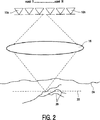
図面の図2を参照すると、レーザドップラシフトを用いて血流を検出する第2の模範的なマルチ画素(multi-pixel)システムにおいて、VCSELダイオードの1次元又は2次元アレイ10a−10n(1次元アレイの場合にはvcsel 1....N、2次元アレイの場合にはvcsel 1*1....n*mと番号付けられる)と、レーザダイオード10により放射された放射線ビーム18を対象の指先の表皮24の下の画像面22に集束する集束レンズ16とが設けられる。反射され、レーザダイオード10a−nのレーザキャビティに再び入るコヒーレント光は、静脈26における血流に依存する自己混合及びレーザフィードバックにより生じた前記レーザの測定可能な強度変調を引き起こし、前記強度変調は、上述のように測定及び処理されることができる。
Referring to FIG. 2 of the drawings, in a second exemplary multi-pixel system for detecting blood flow using laser Doppler shift, a one-dimensional or two-dimensional array 10a-10n (one-dimensional) of VCSEL diodes.
上述の実施例が本発明を限定するのではなく説明し、当業者が、添付の請求項により規定される本発明の範囲から外れることなく多くの代替実施例を設計することができることに注意すべきである。請求項において、括弧内に配置された参照符号は、前記請求項を限定するように解釈されるべきでない。単語"有する"及びその活用形等は、請求項又は全体として明細書に記載された要素又はステップ以外の要素又はステップの存在を除外しない。要素の単数形表示は、複数表示のこのような要素を除外せず、逆も同様である。本発明は、幾つかの別個の要素を有するハードウェアを用いて、及び適切にプログラムされたコンピュータを用いて実施されることができる。幾つかの手段を列挙する装置請求項において、これらの手段の幾つかは、ハードウェアの同一アイテムにより実施されてもよい。特定の方策が相互に異なる請求項に記載されるという単なる事実は、これらの方策の組み合わせが有利に使用されることができないことを示さない。 The above embodiments describe rather than limit the invention, and it should be noted that those skilled in the art can design many alternative embodiments without departing from the scope of the invention as defined by the appended claims. Should. In the claims, any reference signs placed between parentheses shall not be construed as limiting the claim. The word “comprising” and its conjugations do not exclude the presence of elements or steps other than those listed in a claim or as a whole in the specification. The singular representation of an element does not exclude such elements from multiple displays and vice versa. The present invention can be implemented using hardware having several distinct elements and using a suitably programmed computer. In the device claim enumerating several means, several of these means may be embodied by one and the same item of hardware. The mere fact that certain measures are recited in mutually different claims does not indicate that a combination of these measures cannot be used to advantage.
Claims (15)
Applications Claiming Priority (3)
| Application Number | Priority Date | Filing Date | Title |
|---|---|---|---|
| EP04101817 | 2004-04-29 | ||
| EP04101817.7 | 2004-04-29 | ||
| PCT/IB2005/051356 WO2005104935A1 (en) | 2004-04-29 | 2005-04-26 | Apparatus and method for detecting blood flow |
Publications (3)
| Publication Number | Publication Date |
|---|---|
| JP2007534421A JP2007534421A (en) | 2007-11-29 |
| JP2007534421A5 JP2007534421A5 (en) | 2008-06-26 |
| JP4772036B2 true JP4772036B2 (en) | 2011-09-14 |
Family
ID=34965716
Family Applications (1)
| Application Number | Title | Priority Date | Filing Date |
|---|---|---|---|
| JP2007510214A Active JP4772036B2 (en) | 2004-04-29 | 2005-04-26 | Apparatus and method for detecting blood flow |
Country Status (7)
| Country | Link |
|---|---|
| US (1) | US7708695B2 (en) |
| EP (1) | EP1744669B1 (en) |
| JP (1) | JP4772036B2 (en) |
| KR (1) | KR101123179B1 (en) |
| CN (1) | CN1950027B (en) |
| TW (1) | TW200605847A (en) |
| WO (1) | WO2005104935A1 (en) |
Families Citing this family (44)
| Publication number | Priority date | Publication date | Assignee | Title |
|---|---|---|---|---|
| US7844083B2 (en) * | 2004-06-18 | 2010-11-30 | Kyushu Institute Of Technology | Method for acquiring personal identification data, personal identification method, apparatus for acquiring personal identification data, and personal identification apparatus |
| GB2416835C (en) * | 2004-08-04 | 2013-11-06 | Statoil Asa | Method and apparatus for studying surfaces |
| US20080188726A1 (en) * | 2005-02-10 | 2008-08-07 | Koninklijke Philips Electronics, N.V. | Blood Flow Sensor |
| GB2429278B (en) | 2005-08-15 | 2010-08-11 | Statoil Asa | Seismic exploration |
| US8478386B2 (en) | 2006-01-10 | 2013-07-02 | Accuvein Inc. | Practitioner-mounted micro vein enhancer |
| US8838210B2 (en) | 2006-06-29 | 2014-09-16 | AccuView, Inc. | Scanned laser vein contrast enhancer using a single laser |
| US9492117B2 (en) | 2006-01-10 | 2016-11-15 | Accuvein, Inc. | Practitioner-mounted micro vein enhancer |
| US9854977B2 (en) | 2006-01-10 | 2018-01-02 | Accuvein, Inc. | Scanned laser vein contrast enhancer using a single laser, and modulation circuitry |
| US8489178B2 (en) | 2006-06-29 | 2013-07-16 | Accuvein Inc. | Enhanced laser vein contrast enhancer with projection of analyzed vein data |
| US11278240B2 (en) | 2006-01-10 | 2022-03-22 | Accuvein, Inc. | Trigger-actuated laser vein contrast enhancer |
| US10813588B2 (en) | 2006-01-10 | 2020-10-27 | Accuvein, Inc. | Micro vein enhancer |
| US11253198B2 (en) | 2006-01-10 | 2022-02-22 | Accuvein, Inc. | Stand-mounted scanned laser vein contrast enhancer |
| US8730321B2 (en) | 2007-06-28 | 2014-05-20 | Accuvein, Inc. | Automatic alignment of a contrast enhancement system |
| US8463364B2 (en) | 2009-07-22 | 2013-06-11 | Accuvein Inc. | Vein scanner |
| US8594770B2 (en) | 2006-06-29 | 2013-11-26 | Accuvein, Inc. | Multispectral detection and presentation of an object's characteristics |
| US10238294B2 (en) | 2006-06-29 | 2019-03-26 | Accuvein, Inc. | Scanned laser vein contrast enhancer using one laser |
| CN101506827B (en) * | 2006-08-30 | 2012-11-28 | 光谱辨识公司 | System and method for robust fingerprint acquisition |
| JP5071768B2 (en) * | 2006-12-08 | 2012-11-14 | 学校法人日本大学 | Blood flow velocity measuring device |
| WO2009063362A1 (en) * | 2007-11-12 | 2009-05-22 | Koninklijke Philips Electronics N.V. | Universal optical key and lock system and method to initiate a security function |
| GB0803701D0 (en) * | 2008-02-28 | 2008-04-09 | Statoilhydro Asa | Improved interferometric methods and apparatus for seismic exploration |
| JP4600555B2 (en) * | 2008-09-18 | 2010-12-15 | 富士ゼロックス株式会社 | Measuring device |
| JP4600554B2 (en) * | 2008-09-18 | 2010-12-15 | 富士ゼロックス株式会社 | Measuring device |
| US9061109B2 (en) | 2009-07-22 | 2015-06-23 | Accuvein, Inc. | Vein scanner with user interface |
| KR101025666B1 (en) * | 2009-08-25 | 2011-03-30 | 서울대학교산학협력단 | Method and apparatus of extracting finger vein feature point |
| US9259163B2 (en) * | 2011-05-25 | 2016-02-16 | Medtronic, Inc. | Integrated wireless non-invasive perfusion sensor and method of use |
| WO2012164438A1 (en) * | 2011-06-01 | 2012-12-06 | Koninklijke Philips Electronics N.V. | Determining a flow characteristic of an object being movable in an element |
| US9031641B2 (en) | 2011-07-28 | 2015-05-12 | Medtronic, Inc. | Quantifying laser-doppler perfusion signal for arrhythmia detection and disease monitoring |
| KR101288178B1 (en) | 2011-11-30 | 2013-07-19 | 삼성전기주식회사 | Sensor and method for detecting fingerprint |
| US9848787B2 (en) | 2012-02-07 | 2017-12-26 | Laser Associated Sciences, Inc. | Perfusion assessment using transmission laser speckle imaging |
| US9072426B2 (en) | 2012-08-02 | 2015-07-07 | AccuVein, Inc | Device for detecting and illuminating vasculature using an FPGA |
| TWI536272B (en) * | 2012-09-27 | 2016-06-01 | 光環科技股份有限公司 | Bio-characteristic verification device and method |
| US10376148B2 (en) | 2012-12-05 | 2019-08-13 | Accuvein, Inc. | System and method for laser imaging and ablation of cancer cells using fluorescence |
| CN104042220A (en) * | 2014-05-28 | 2014-09-17 | 上海思立微电子科技有限公司 | Device and method for detecting living body fingerprint |
| WO2016117106A1 (en) * | 2015-01-23 | 2016-07-28 | オリンパス株式会社 | Surgical treatment device |
| TWI549065B (en) * | 2015-01-26 | 2016-09-11 | Gingytech Technology Inc | Fingerprint identification method and device thereof |
| US9722793B2 (en) | 2015-09-09 | 2017-08-01 | Microsoft Technology Licensing, Llc | Personal identification via acoustically stimulated biospeckles |
| CN105512636A (en) * | 2015-12-19 | 2016-04-20 | 南京福瑞林生物科技有限公司 | Living fingerprint identification device and living fingerprint identification method |
| KR102579895B1 (en) | 2016-08-26 | 2023-09-19 | 삼성전자 주식회사 | Electronic device and a method for measuring heart rate based on an infrared rays sensor using the same |
| US10813597B2 (en) | 2017-04-14 | 2020-10-27 | The Regents Of The University Of California | Non-invasive hemodynamic assessment via interrogation of biological tissue using a coherent light source |
| EP4357790A1 (en) * | 2018-04-24 | 2024-04-24 | Sony Group Corporation | Scattered light signal measuring device, and information processing device |
| CN113423335A (en) * | 2019-02-11 | 2021-09-21 | 株式会社高迎科技 | Blood flow measuring device and blood flow measuring method |
| WO2023227373A1 (en) * | 2022-05-23 | 2023-11-30 | Ams International Ag | Self-mixing interferometry sensor module for authentication, electronic device and method of detecting a fingerprint |
| WO2023232460A1 (en) * | 2022-05-30 | 2023-12-07 | Ams International Ag | Self-mixing interferometry sensor module for multilayer target detection, electronic device and method of multilayer target detection |
| EP4309573A1 (en) | 2022-07-21 | 2024-01-24 | Sonion Nederland B.V. | Determination of a parameter related to blood flow in a blood perfused part using a vcsel |
Citations (3)
| Publication number | Priority date | Publication date | Assignee | Title |
|---|---|---|---|---|
| JPH07313475A (en) * | 1994-05-30 | 1995-12-05 | Terumo Corp | Flow velocity sensor probe |
| JPH10260254A (en) * | 1997-03-19 | 1998-09-29 | Suzuki Motor Corp | Self-mixing laser velocity meter |
| WO2002037411A1 (en) * | 2000-11-06 | 2002-05-10 | Koninklijke Philips Electronics N.V. | Optical input device for measuring finger movement |
Family Cites Families (15)
| Publication number | Priority date | Publication date | Assignee | Title |
|---|---|---|---|---|
| US237410A (en) * | 1881-02-08 | Lyman v | ||
| US4393366A (en) * | 1981-02-17 | 1983-07-12 | Eye-D Development Ii Ltd. | Rotating beam ocular identification apparatus and method |
| US4699149A (en) * | 1984-03-20 | 1987-10-13 | Joseph Rice | Apparatus for the identification of individuals |
| AU608807B2 (en) * | 1987-03-03 | 1991-04-18 | Hitoshi Fujii | Apparatus for monitoring bloodstream |
| JPH02268727A (en) * | 1989-04-10 | 1990-11-02 | Kowa Co | Method and apparatus for ophthalmologic measurement |
| GB9306897D0 (en) * | 1993-04-01 | 1993-05-26 | British Tech Group | Biometric identification of individuals |
| KR0136977B1 (en) * | 1994-04-04 | 1998-04-24 | 박승덕 | Apparatus for measuring blood flow by laser doppler |
| US5737439A (en) * | 1996-10-29 | 1998-04-07 | Smarttouch, Llc. | Anti-fraud biometric scanner that accurately detects blood flow |
| JP3567651B2 (en) | 1996-11-06 | 2004-09-22 | 株式会社日立製作所 | Biological identification device |
| JP2001120509A (en) * | 1999-10-29 | 2001-05-08 | Cyber Firm Inc | Bloodstream signal extracting apparatus and bloodstream signal extracting method |
| JP2002092616A (en) * | 2000-09-20 | 2002-03-29 | Hitachi Ltd | Individual authentication device |
| ATE454845T1 (en) * | 2000-10-30 | 2010-01-15 | Gen Hospital Corp | OPTICAL SYSTEMS FOR TISSUE ANALYSIS |
| CA2413483A1 (en) * | 2001-12-26 | 2003-06-26 | Kevin R. Forrester | Motion measuring device |
| US7213600B2 (en) * | 2002-04-03 | 2007-05-08 | The Procter & Gamble Company | Method and apparatus for measuring acute stress |
| US20050157971A1 (en) * | 2002-05-17 | 2005-07-21 | Rene Juijve | Apparatus comprising an optical input device and at least one further optical device having a common radiation source |
-
2005
- 2005-04-26 US US11/568,395 patent/US7708695B2/en active Active
- 2005-04-26 KR KR1020067022136A patent/KR101123179B1/en active IP Right Grant
- 2005-04-26 EP EP05732776.9A patent/EP1744669B1/en active Active
- 2005-04-26 WO PCT/IB2005/051356 patent/WO2005104935A1/en not_active Application Discontinuation
- 2005-04-26 JP JP2007510214A patent/JP4772036B2/en active Active
- 2005-04-26 CN CN2005800136369A patent/CN1950027B/en active Active
- 2005-04-28 TW TW094113764A patent/TW200605847A/en unknown
Patent Citations (4)
| Publication number | Priority date | Publication date | Assignee | Title |
|---|---|---|---|---|
| JPH07313475A (en) * | 1994-05-30 | 1995-12-05 | Terumo Corp | Flow velocity sensor probe |
| JPH10260254A (en) * | 1997-03-19 | 1998-09-29 | Suzuki Motor Corp | Self-mixing laser velocity meter |
| WO2002037411A1 (en) * | 2000-11-06 | 2002-05-10 | Koninklijke Philips Electronics N.V. | Optical input device for measuring finger movement |
| JP2004513441A (en) * | 2000-11-06 | 2004-04-30 | コーニンクレッカ フィリップス エレクトロニクス エヌ ヴィ | Optical input device for measuring finger movement |
Also Published As
| Publication number | Publication date |
|---|---|
| US20080234590A1 (en) | 2008-09-25 |
| KR101123179B1 (en) | 2012-03-19 |
| KR20070004892A (en) | 2007-01-09 |
| WO2005104935A1 (en) | 2005-11-10 |
| US7708695B2 (en) | 2010-05-04 |
| EP1744669A1 (en) | 2007-01-24 |
| CN1950027B (en) | 2010-05-26 |
| CN1950027A (en) | 2007-04-18 |
| TW200605847A (en) | 2006-02-16 |
| EP1744669B1 (en) | 2019-03-27 |
| JP2007534421A (en) | 2007-11-29 |
Similar Documents
| Publication | Publication Date | Title |
|---|---|---|
| JP4772036B2 (en) | Apparatus and method for detecting blood flow | |
| US11645862B2 (en) | Interactive biometric touch scanner | |
| US7817256B2 (en) | Personal authentication method and personal authentication device utilizing finger-tip blood flow measurement by laser light | |
| KR101923335B1 (en) | Multifunction fingerprint sensor with light detection to prevent forgery of fingerprint | |
| KR102061434B1 (en) | Systems and Methods for Spoof Detection and Liveness Analysis | |
| JP4951291B2 (en) | Biometric authentication device | |
| US9195900B2 (en) | System and method based on hybrid biometric detection | |
| US5737439A (en) | Anti-fraud biometric scanner that accurately detects blood flow | |
| JP2007534421A5 (en) | ||
| JP5096168B2 (en) | Optical speckle pattern inspection | |
| US8494228B2 (en) | Personal authentication method using subcutaneous bloodstream measurement and personal authentication device | |
| KR102146089B1 (en) | Anti-spoofing method and system of a device having a fingerprint sensor | |
| WO2005122896A1 (en) | Personal identification method by subcutaneous bloodstream measurement and personal identification device | |
| JP2007537526A (en) | Method and apparatus for personal identification | |
| JP5990906B2 (en) | Measuring device, measuring method, program, and recording medium | |
| US9971948B1 (en) | Vein imaging using detection of pulsed radiation | |
| KR20160117864A (en) | A Fingerprint Identifier and a Fingerprint Identifying Method | |
| WO2023026300A1 (en) | An optical fingerprint scanner | |
| KR20160117862A (en) | A Fingerprint Identifier and a Fingerprint Identifying Method |
Legal Events
| Date | Code | Title | Description |
|---|---|---|---|
| A521 | Request for written amendment filed |
Free format text: JAPANESE INTERMEDIATE CODE: A523 Effective date: 20080425 |
|
| A621 | Written request for application examination |
Free format text: JAPANESE INTERMEDIATE CODE: A621 Effective date: 20080425 |
|
| A977 | Report on retrieval |
Free format text: JAPANESE INTERMEDIATE CODE: A971007 Effective date: 20101216 |
|
| A131 | Notification of reasons for refusal |
Free format text: JAPANESE INTERMEDIATE CODE: A131 Effective date: 20110125 |
|
| A521 | Request for written amendment filed |
Free format text: JAPANESE INTERMEDIATE CODE: A523 Effective date: 20110425 |
|
| TRDD | Decision of grant or rejection written | ||
| A01 | Written decision to grant a patent or to grant a registration (utility model) |
Free format text: JAPANESE INTERMEDIATE CODE: A01 Effective date: 20110524 |
|
| A61 | First payment of annual fees (during grant procedure) |
Free format text: JAPANESE INTERMEDIATE CODE: A61 Effective date: 20110621 |
|
| FPAY | Renewal fee payment (event date is renewal date of database) |
Free format text: PAYMENT UNTIL: 20140701 Year of fee payment: 3 |
|
| R150 | Certificate of patent or registration of utility model |
Ref document number: 4772036 Country of ref document: JP Free format text: JAPANESE INTERMEDIATE CODE: R150 |
|
| R250 | Receipt of annual fees |
Free format text: JAPANESE INTERMEDIATE CODE: R250 |
|
| R250 | Receipt of annual fees |
Free format text: JAPANESE INTERMEDIATE CODE: R250 |
|
| R250 | Receipt of annual fees |
Free format text: JAPANESE INTERMEDIATE CODE: R250 |
|
| R250 | Receipt of annual fees |
Free format text: JAPANESE INTERMEDIATE CODE: R250 |
|
| R250 | Receipt of annual fees |
Free format text: JAPANESE INTERMEDIATE CODE: R250 |
|
| R250 | Receipt of annual fees |
Free format text: JAPANESE INTERMEDIATE CODE: R250 |
|
| R250 | Receipt of annual fees |
Free format text: JAPANESE INTERMEDIATE CODE: R250 |
|
| R250 | Receipt of annual fees |
Free format text: JAPANESE INTERMEDIATE CODE: R250 |
|
| R250 | Receipt of annual fees |
Free format text: JAPANESE INTERMEDIATE CODE: R250 |
|
| R250 | Receipt of annual fees |
Free format text: JAPANESE INTERMEDIATE CODE: R250 |