JP4767782B2 - Medical imaging device - Google Patents
Medical imaging device Download PDFInfo
- Publication number
- JP4767782B2 JP4767782B2 JP2006203649A JP2006203649A JP4767782B2 JP 4767782 B2 JP4767782 B2 JP 4767782B2 JP 2006203649 A JP2006203649 A JP 2006203649A JP 2006203649 A JP2006203649 A JP 2006203649A JP 4767782 B2 JP4767782 B2 JP 4767782B2
- Authority
- JP
- Japan
- Prior art keywords
- cross
- image
- organ
- deformation
- sectional
- Prior art date
- Legal status (The legal status is an assumption and is not a legal conclusion. Google has not performed a legal analysis and makes no representation as to the accuracy of the status listed.)
- Expired - Fee Related
Links
- 238000002059 diagnostic imaging Methods 0.000 title claims description 32
- 210000000056 organ Anatomy 0.000 claims description 107
- 230000005484 gravity Effects 0.000 claims description 51
- 238000005452 bending Methods 0.000 claims description 15
- 238000006073 displacement reaction Methods 0.000 claims description 14
- 238000000605 extraction Methods 0.000 claims description 2
- 238000000034 method Methods 0.000 description 20
- 206010028980 Neoplasm Diseases 0.000 description 8
- 201000011510 cancer Diseases 0.000 description 8
- 230000009466 transformation Effects 0.000 description 5
- 238000004364 calculation method Methods 0.000 description 4
- 238000010586 diagram Methods 0.000 description 4
- 210000004185 liver Anatomy 0.000 description 4
- 230000011218 segmentation Effects 0.000 description 4
- 238000003384 imaging method Methods 0.000 description 3
- 238000001356 surgical procedure Methods 0.000 description 2
- 230000008961 swelling Effects 0.000 description 2
- 210000000481 breast Anatomy 0.000 description 1
- 238000003745 diagnosis Methods 0.000 description 1
- 230000006870 function Effects 0.000 description 1
- 239000004973 liquid crystal related substance Substances 0.000 description 1
- 230000004048 modification Effects 0.000 description 1
- 238000012986 modification Methods 0.000 description 1
- 230000002093 peripheral effect Effects 0.000 description 1
- 238000004088 simulation Methods 0.000 description 1
- 210000000779 thoracic wall Anatomy 0.000 description 1
- 238000002054 transplantation Methods 0.000 description 1
Images


Description
本発明は、医療画像装置に係り、特に断層像に写っている臓器を変形させる医療画像装置に関する。 The present invention relates to a medical imaging apparatus, and more particularly to a medical imaging apparatus that deforms an organ shown in a tomographic image.
X線CT装置、MR装置、超音波画像装置等の医療画像装置で撮影した被検体の画像を用いて、被検体の臓器等の3次元画像を表示させて、外科手術、診断等を支援する装置が用いられている。 Supports surgery, diagnosis, etc. by displaying 3D images of the organ of the subject using the image of the subject taken by a medical imaging device such as an X-ray CT device, MR device, ultrasonic imaging device, etc. The device is used.
しかし、手術時に臓器を手で触れる、臓器を体外へ持ち出す等する場合には臓器が変形し、臓器の状態が医療画像装置に表示されている臓器の3次元画像の状態と異なるという問題がある。 However, when the organ is touched by hand or taken out of the body during surgery, the organ is deformed, and the state of the organ is different from the state of the three-dimensional image of the organ displayed on the medical imaging device. .
これに対応するために、時間の異なる2つの画像データから臓器の変形を示す式を定義し、その式を空間の各点について定義された重み付け関数を用いて3次元空間における変形を定義する方法及び装置が開示されている。
しかしながら、上記特許文献1では以下のような技術課題に配慮されていなかった。特許文献1では、時間と共に変形し得る臓器の変形を3次元で得る方法であって、重力を考慮した自然な臓器の変形を得るものではない。また、臓器の変形が認識できる2個以上のデータが必要であるため、手術時に臓器を手で触れる、臓器を体外へ持ち出す等する場合の臓器の変形を、実際にデータを得ること無しに得ることはできない。
However, the above-mentioned
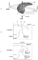
例えば、図11(a)は肝臓が体内にある場合であるが、体外に出した場合は、一般に図11(b)に示すように重力により変形する。図12は、肝臓移植手術の直前に作られて、移植肝臓の切り方などを検討するのに使われている画像であるが、切断のために体外に出した際の重力による変形が考慮されていないため、より正確な手術のシミュレーションの情報が望まれていた。 For example, FIG. 11 (a) shows a case where the liver is inside the body, but when it is outside the body, it is generally deformed by gravity as shown in FIG. 11 (b). FIG. 12 is an image made immediately before the liver transplantation operation and used for examining how to cut the transplanted liver, etc., but considering deformation due to gravity when it is taken out of the body for cutting. Therefore, more accurate surgical simulation information was desired.
本発明は、上記事情に鑑みてなされたものであり、重力によって変形した臓器の画像(望ましくは3次元画像)を得ることができる医療画像装置を提供することを目的とする。 The present invention has been made in view of the above circumstances, and an object thereof is to provide a medical imaging apparatus capable of obtaining an image (preferably a three-dimensional image) of an organ deformed by gravity.
前記課題を解決するために、本発明の医療画像装置は、被検体の臓器領域を含む複数枚の断層像を取得する画像取得手段と、前記画像取得手段によって取得された複数枚の断層像から臓器領域を抽出する臓器抽出手段と、前記抽出された臓器領域を複数の分割面に分割するための基準となる分割軸を設定する分割軸設定手段と、前記分割軸を通る複数の分割面上に前記抽出された臓器領域の第1の断面像を作成する断面像作成手段と、前記断面像作成手段で作成された第1の断面像を重力の影響を受けた第2の断面像に変形させる断面像変形手段と、前記断面像変形手段によって変形させられた複数の第2の断面像に基づいて所望の表示画像を作成する表示画像作成手段と、前記表示画像作成手段によって作成された表示画像を表示する表示手段と、を備えたことを特徴としている。上記の医療画像装置によれば、重力方向と平行な分割軸を通る複数の分割面において被検体の臓器領域の重力による変形を行い、これを基にして被検体の臓器領域の重力による変形後の画像を表示させる。これにより、変形後の臓器のデータを得ることなく、重力によって変形した臓器の画像を得ることができる。 In order to solve the above problems, a medical imaging apparatus according to the present invention includes an image acquisition unit that acquires a plurality of tomographic images including an organ region of a subject, and a plurality of tomographic images acquired by the image acquisition unit. and organ extracting means for extracting an organ region, wherein the dividing axis setting means for setting a dividing axis as a reference for dividing the extracted organ region into a plurality of divided surfaces, the divided shaft passing Ru multiple divide A cross-sectional image creating means for creating a first cross-sectional image of the extracted organ region on a surface; and a second cross-sectional image under the influence of gravity of the first cross-sectional image created by the cross-sectional image creating means. A cross-sectional image deforming unit that deforms the display image, a display image creating unit that creates a desired display image based on a plurality of second cross-sectional images deformed by the cross-sectional image deforming unit, and a display image creating unit Display to display the displayed image Is characterized by comprising: a stage, a. According to the above medical imaging apparatus, the organ region of the subject is deformed by gravity on a plurality of division planes passing through the division axis parallel to the direction of gravity, and the organ region of the subject is deformed by gravity based on the deformation. Display the image. Thereby, an image of an organ deformed by gravity can be obtained without obtaining data of the deformed organ.
また、本発明の医療画像装置は、前記断面像変形手段は、重力による曲げ、ズレ、膨らみのうちの少なくとも1つの変形形態で前記第1の断面像を変形させて前記第2の断面像を作成することが望ましい。上記の医療画像装置によれば、被検体の臓器領域の重力による変形は、曲げ、ズレ、膨らみのうちの少なくとも1つの変形形態による。これにより、重力による臓器の変形を適切に表現することができる。なお、前記重力による曲げは、CT値によって異なる所定の変形係数に基づいて計算された変形角度で前記臓器領域内の線を回転させる変形形態であり、前記重力によるズレは、CT値によって異なる所定の変形係数に基づいて計算された変位で前記臓器領域内の点を重量方向にずり落ちるように移動させる変形形態であり、前記重力による膨らみは、CT値によって異なる所定の変形係数に基づいて計算された変位で、かつ前記臓器領域の面積が等しくなるように前記臓器領域を横方向に変形させる変形形態である。 The medical imaging apparatus of the present invention, the pre-Symbol sectional image deforming means, bending by gravity, displacement, bulging at least one variant the second cross-sectional image by deforming the first sectional image in the form of It is desirable to create. According to the above medical imaging apparatus, the deformation of the organ region of the subject due to gravity depends on at least one of deformation forms of bending, displacement, and swelling. Thereby, the deformation | transformation of the organ by gravity can be expressed appropriately. Note that the bending due to gravity is a deformation mode in which a line in the organ region is rotated at a deformation angle calculated based on a predetermined deformation coefficient that varies depending on the CT value, and the displacement due to the gravity varies depending on the CT value. In this deformation mode, a point in the organ region is moved so as to slide down in the weight direction with a displacement calculated based on the deformation coefficient of the gravity, and the bulge due to gravity is calculated based on a predetermined deformation coefficient that differs depending on the CT value. This is a modification in which the organ region is deformed in the lateral direction so that the areas of the organ region are equal to each other.
また、本発明の医療画像装置は、前記表示画像生成手段は、前記複数の第2の断面像から作成した複数の平行な断面像を用いて、又は前記複数の第2の断面像を用いて直接3次元画像を作成し、この3次元画像を表示画像とすることが望ましい。上記の医療画像装置によれば、被検体の臓器領域の重力による変形後の画像は3次元画像であり、その3次元画像は、複数の第2の断面像から作成した複数の平行な断面像を用いて作成される、又は複数の第2の断面像を用いて直接作成される。これにより、直接的で容易に立体的な認識が可能な重力によって変形した臓器の画像を得ることができる。 The medical imaging apparatus of the present invention, prior Symbol display image generating means uses a plurality of parallel sectional image created from said plurality of second cross-sectional images, or using the plurality of second cross-sectional images It is desirable to directly create a three-dimensional image and use this three-dimensional image as a display image. According to the above medical imaging apparatus, the image of the organ region of the subject after deformation due to gravity is a three-dimensional image, and the three-dimensional image is a plurality of parallel sectional images created from a plurality of second sectional images. Or directly using a plurality of second cross-sectional images. This makes it possible to obtain an image of an organ deformed by gravity that allows direct and easy three-dimensional recognition.
本発明によれば、重力によって変形した臓器の画像(望ましくは3次元画像)を得ることができる医療画像装置を提供することができる。 According to the present invention, it is possible to provide a medical imaging apparatus that can obtain an image (preferably a three-dimensional image) of an organ deformed by gravity.
以下、本発明を実施するための最良の形態を添付図面に基づいて説明する。 The best mode for carrying out the present invention will be described below with reference to the accompanying drawings.
図1は、本発明に係る第1の実施の形態の医療画像装置全体の構成を示すハードウェア構成図である。 FIG. 1 is a hardware configuration diagram showing the overall configuration of the medical image apparatus according to the first embodiment of the present invention.
医療画像装置10は、被検体の画像を撮影する医用画像撮影装置2とLAN3等のネットワークによって接続される。医用画像撮影装置は、例としてX線CT装置を記載したが、MR装置や超音波撮影装置のように被検体の画像(好ましくは3次元画像)を撮影可能な装置により構成される。
The
医療画像装置10は、主として各構成要素の動作を制御する制御装置としての中央処理装置(CPU)11、装置の制御プログラムが格納されたり、プログラム実行時の作業領域となったりする主メモリ12と、オペレーティングシステム(OS)、周辺機器のデバイスドライブ、胸壁の厚さの測定等の処理を行うためのプログラムを含む各種アプリケーションソフト等が格納される磁気ディスク13と、表示用データを一時記憶する表示メモリ14と、この表示メモリ14からのデータに基づいて画像を表示するCRTモニタや液晶モニタ等のモニタ15と、位置入力装置としてのマウス17、マウス17の状態を検出してモニタ15上のマウスポインタの位置やマウス17の状態等の信号をCPU11に出力するコントローラ16と、操作者が支持を入力するためのキーボード18と、上記各構成要素を接続するバス19とから構成される。
The
CPU11は、上記プログラムを磁気ディスク13から読み出して主メモリ12にロードし、実行する。
The
なお、本実施例では、主メモリ12以外の記憶装置として磁気ディスク13が接続されているが、それ以外にハードディスクドライブ等が接続されていてもよい。
In this embodiment, the
次に、医療画像装置10の処理の流れを説明する。
Next, a processing flow of the
図2は、医療画像装置10の処理の流れを示すフローチャートである。CPU11は、このフローチャートに従って動作する。以下の処理は、被検体の臓器領域を撮影した画像データ(アキシャル画像等の複数の断層像)が医用画像撮影装置2から医療画像装置10へ読みこまれた後で開始される。
FIG. 2 is a flowchart showing the flow of processing of the
ステップS10では、医用画像撮影装置2から入力された複数の画像データから臓器領域を抽出する。図3(a)に示す複数の断層像Aは、臓器領域の抽出後の画像(二値画像)である。複数の断層像Aにより、臓器Cが認識される。
In step S10, an organ region is extracted from a plurality of image data input from the medical
ステップS12では、図3(a)に示すように分割軸Lを設定する。分割軸Lは臓器Cに対して任意の位置、角度で設定が可能である。一般に、分割軸Lは、被検体から臓器Cを取り出した場合に臓器Cを乗せる支持物体を通るように設定される。また、臓器Cを手に持った場合は手を通るように設定される。 In step S12, the division axis L is set as shown in FIG. The division axis L can be set at an arbitrary position and angle with respect to the organ C. In general, the division axis L is set so as to pass through a supporting object on which the organ C is placed when the organ C is extracted from the subject. Further, when the organ C is held in the hand, it is set so as to pass through the hand.
なお、図3(a)においては、認識しやすくするために、臓器に対して任意の位置、角度に設定した分割軸Lが重力方向に平行な向き(垂直下向き)になるように配置した。 In FIG. 3A, for easy recognition, the division axis L set at an arbitrary position and angle with respect to the organ is arranged in a direction parallel to the gravity direction (vertical downward).
次に、複数の断層像Aから断面像Cn(n=1〜N)を作成する方法について説明する(ステップS14〜S28)。 Next, a method for creating a cross-sectional image Cn (n = 1 to N) from a plurality of tomographic images A will be described (steps S14 to S28).
ステップS14では、n=1に設定する。 In step S14, n = 1 is set.
ステップS16では、分割軸Lを通る分割面Bn(n=1〜N)を設定する。図3(a)においては、分割軸Lが臓器Cの内部を通るように設定されているため、分割面Bn(n=1〜N)は分割軸Lを中心に放射状に設定される。分割面Bnは、分割面B1から時計回りに順番にB1、B2・・・、Bnと設定され、分割軸Lを中心に1周する。 In step S16, it sets the passing Ru split plane Bn (n = 1~N) split shaft L. In FIG. 3A, since the division axis L is set so as to pass through the inside of the organ C, the division plane Bn (n = 1 to N) is set radially about the division axis L. The dividing plane Bn is set as B1, B2,..., Bn in order clockwise from the dividing plane B1, and makes one round around the dividing axis L.
ステップS18では、n=n+1に設定する。 In step S18, n = n + 1 is set.
ステップS20では、n=Nであるかどうか、すなわちすべての分割面Bn(n=1〜N)が作成されたかを判断する。YESの場合はステップS22へ進み、NOの場合はステップS16へ戻る。 In step S20, it is determined whether n = N, that is, whether all the divided surfaces Bn (n = 1 to N) have been created. If yes, then continue with step S22, otherwise, return to step S16.
ステップS22では、n=1に設定する。 In step S22, n = 1 is set.
ステップS24では、分割面Bn(n=1〜N)上に臓器Cの断面像Cn(n=1〜N)を補間演算により作成する。図3(b)に示すように、分割面B1における臓器Cの断面像は断面像C1である。なお、補間演算は既に公知の様々な補間法を用いることができる。 In step S24, a cross-sectional image Cn (n = 1 to N) of the organ C is created by interpolation calculation on the dividing plane Bn (n = 1 to N). As shown in FIG. 3B, the cross-sectional image of the organ C on the dividing plane B1 is a cross-sectional image C1. Note that various known interpolation methods can be used for the interpolation calculation.
ステップS26では、n=n+1に設定する。 In step S26, n = n + 1 is set.
ステップS28では、n=Nであるかどうか、すなわちすべての分割面Bn(n=1〜N)に対して断面像Cn(n=1〜N)が作成されたかを判断する。YESの場合はステップS30へ進み、NOの場合はステップS24へ戻る。 In step S28, it is determined whether or not n = N, that is, whether or not the cross-sectional images Cn (n = 1 to N) have been created for all the divided surfaces Bn (n = 1 to N). If yes, then continue with step S30, otherwise, return to step S24.
これにより、分割面B1〜BNに対して断面像C1〜CNが作成される。 Thereby, the cross-sectional images C1-CN are created with respect to the dividing surfaces B1-BN.
次に、断面像Cn(n=1〜N)を重力の影響を受けた断面像Cn’(n=1〜N)を作成する方法について説明する(ステップS30〜S36)。 Next, a method of creating a cross-sectional image Cn ′ (n = 1 to N) that is affected by gravity from the cross-sectional image Cn (n = 1 to N) will be described (steps S30 to S36).
ステップS30では、n=1に設定する。 In step S30, n = 1 is set.
ステップS32では、断面像Cn(n=1〜N)を重力によって変形された臓器の断面像Cn’(n=1〜N)に変形させる(図3(c)参照)。変形の方法(変形形態)には、曲げ、ズレ、膨らみの3種類があり、上記3種類のうちの少なくとも1つの変形形態により変形が行われる。どの変形形態により変形が行われるかは、臓器の形状、種類、状態等によって決定される。図3(c)の場合には、臓器Cは肝臓であり、曲げと膨らみとの2種類の変形形態によって変形が行われる。 In step S32, the cross-sectional image Cn (n = 1 to N) is transformed into a cross-sectional image Cn ′ (n = 1 to N) of the organ deformed by gravity (see FIG. 3C). There are three types of deformation methods (deformation modes): bending, misalignment, and bulging, and the deformation is performed by at least one of the above three types of deformation modes. Which deformation mode is used for the deformation is determined by the shape, type, state, etc. of the organ. In the case of FIG.3 (c), the organ C is a liver and a deformation | transformation is performed by two types of deformation forms, a bending and a swelling.
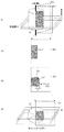
臓器Cを支持物体に載せた場合には、支持物体に載せられた部分の重力変形は無視できるので、支持物体の形に合わせて非線形領域を設定する。図4(a)に示すように支持物体を置いた場合には、図4(b)に示すように、支持物体の上部に非変形領域が設定される。非変形領域が設定された場合には、非変形領域以外の領域(変形領域)において、曲げ、ズレ、膨らみのうちの少なくとも1つの変形形態により変形が行われる。なお、上記においては、臓器Cを支持物体に載せた場合について説明したが、臓器Cを手に持った場合についても同様である。また、臓器Cを支持物体に載せた状態で、臓器Cの支持物体に乗せられていない部分を手で持った場合については、臓器Cの支持物体に乗せられた部分と手で保持された部分とを非変形領域と設定すればよい。 When the organ C is placed on the support object, the gravity deformation of the part placed on the support object can be ignored, so the nonlinear region is set according to the shape of the support object. When a supporting object is placed as shown in FIG. 4A, a non-deformation region is set above the supporting object as shown in FIG. 4B. When the non-deformation region is set, the region is deformed by at least one deformation mode among bending, misalignment, and bulge in the region (deformation region) other than the non-deformation region. In the above description, the case where the organ C is placed on the supporting object has been described, but the same applies to the case where the organ C is held in the hand. In the case where the organ C is placed on the support object and the part that is not placed on the support object of the organ C is held by hand, the part placed on the support object of the organ C and the part held by the hand May be set as a non-deformation region.
ステップS34では、n=n+1に設定する。 In step S34, n = n + 1 is set.
ステップS36では、n=Nであるかどうか、すなわちすべての分割面Bn(n=1〜N)に対して断面像Cn(n=1〜N)が断面像Cn’(n=1〜N)に変形されたかを判断する。YESの場合はステップS30へ進み、NOの場合はステップS24へ戻る。 In step S36, whether or not n = N, that is, the cross-sectional image Cn (n = 1 to N) is the cross-sectional image Cn ′ (n = 1 to N) with respect to all the divided surfaces Bn (n = 1 to N). It is determined whether or not it has been deformed. If yes, then continue with step S30, otherwise, return to step S24.
これにより、断面像C1〜CNに対して重力の影響を受けた断面像C1’〜CN’が作成される。 As a result, cross-sectional images C1 'to CN' that are affected by gravity are generated on the cross-sectional images C1 to CN.
次に、重力の影響を受けた断面像Cn’(n=1〜N)を用いてモニタ15に表示させる表示画像である3次元画像を作成する方法について説明する。
Next, a method of creating a three-dimensional image that is a display image to be displayed on the
ステップS38では、変形した断面像Cn’(n=1〜N)から複数の断層像A’を補間演算により作成する(図3(d)参照)。この断層像A’は、断層像Aと平行でもよいし、平行でなくてもよい。なお、補間演算は既に公知の様々な補間法を用いることができる。 In step S38, a plurality of tomographic images A ′ are created from the deformed cross-sectional images Cn ′ (n = 1 to N) by interpolation (see FIG. 3D). This tomographic image A ′ may or may not be parallel to the tomographic image A. Note that various known interpolation methods can be used for the interpolation calculation.
ステップS40では、断層像A’を用いて臓器Cの3次元画像を作成する。 In step S40, a three-dimensional image of the organ C is created using the tomographic image A '.
これにより、モニタ15に表示させる表示画像である3次元画像が作成される。なお、ステップS30は省略可能であり、ステップS28でYESの場合には、演算時間は余計にかかるが、断面像Cn’(n=1〜N)から直接3次元画像を作成してもよい。
Thereby, a three-dimensional image which is a display image to be displayed on the
このようにして作成された3次元画像は、図8に示すように、モニタ上に表示される。 The three-dimensional image created in this way is displayed on the monitor as shown in FIG.
次に、曲げ、ズレ、膨らみの3種類の変形形態の詳細について説明する。 Next, details of the three types of deformation modes, that is, bending, misalignment, and bulging will be described.
曲げとは、変形前の断面像D1上のある点pにおいて、線p1が点pを中心にして角度θ回転して線p2へ移動するような変形形態である(図4(b)参照)。曲げの変形形態において、角度θは変形角度であり、この変形角度は臓器の形状、種類、状態等によって所定の値に定められている変形係数に基づいて計算される。例えば、癌領域とそうでない領域とでは変形係数が異なるため、癌領域がある場合(図4(c)参照)と癌領域がない場合(図4(b)参照)とでは、変形角度が異なる。すなわち、変形前の断面図D1、E1が同じ場合において、癌領域がない場合の変形後の断面図D1と’癌領域がある場合の変形後の画像E1’とは異なる。癌領域がある場合には、癌領域がない場合に比べてCT値が異なるため、図5に示すように、変形係数はCT値に対応させて与えるのが分かりやすく便利である。なお、上記において、変形係数がCT値によって異なることを曲げの変形形態を例に説明したが、下記のズレ、膨らみを含む全ての変形形態において、変形係数がCT値によって異なる。また、CT値と変形係数との関係は図5に示す例に限らない。 Bending is a deformation form in which, at a certain point p on the cross-sectional image D1 before deformation, the line p1 rotates by an angle θ about the point p and moves to the line p2 (see FIG. 4B). . In the bending deformation mode, the angle θ is a deformation angle, and this deformation angle is calculated based on a deformation coefficient set to a predetermined value depending on the shape, type, state, etc. of the organ. For example, since the deformation coefficient is different between the cancer region and the other region, the deformation angle is different between the case where there is a cancer region (see FIG. 4C) and the case where there is no cancer region (see FIG. 4B). . That is, when the sectional views D1 and E1 before deformation are the same, the sectional view D1 after deformation when there is no cancer region and the image E1 after deformation when there is a cancer region are different. When there is a cancer region, the CT value is different from that when there is no cancer region. Therefore, as shown in FIG. 5, it is easy to understand that it is convenient to provide the deformation coefficient corresponding to the CT value. In the above description, the deformation coefficient varies depending on the CT value. The bending deformation mode has been described as an example. However, in all deformation modes including the following deviation and bulge, the deformation coefficient varies depending on the CT value. Further, the relationship between the CT value and the deformation coefficient is not limited to the example shown in FIG.
ズレとは、変形前の断面像F1上のあるqnにおいて、重力方向にずり落ちるように距離α移動する変形形態である(図6(c)参照)。図6(a)は変形前の臓器Fを示し、図6(b)は分割面B1上の臓器Fの断面像F1を示し、図6(c)は、断面像F1がズレの変形形態によって移動して断面像F1’に変形したところを示し、図6(d)は変形後の臓器F’を示す。図6は臓器D(例えば乳房)のズレの変形形態のみによって変形する部分を抜き出した例であり、臓器Dの一部分を抜き出しているため、分割軸Lは無限遠方にあると仮定する。よって、図6(a)に示すように、分割面Bn(n=1〜N)が平行になっている。ズレの変形形態において、距離αは変位であり、この変位は臓器の形状、種類、状態等によって所定の値に定められている変形係数に基づいて計算される
膨らみとは、重力による垂直な力によって臓器が横方向に変形を生じるように移動する変形形態である(図7(c)参照)。図7(a)は変形前の臓器Gを示し、図7(b)は分割面B1上の臓器Gの断面像G1を示し、図7(c)は、断面像G1が膨らみの変形形態によって移動して断面像G1’に変形したところを示し、図7(d)は変形後の臓器G’を示す。横方向の変形量βは、変形前の臓器Gと変形後の臓器G’の体積、すなわち変形前の断面像G1の面積と変形後の断面像G1’の面積とが等しくなるように決定される。膨らみの変形形態において、変形量βは変位であり、この変位は臓器の形状、種類、状態等によって所定の値に定められている変形係数に基づいて計算される。
The shift is a deformation form in which a distance α moves so as to slide down in the direction of gravity in a certain qn on the cross-sectional image F1 before deformation (see FIG. 6C). 6A shows the organ F before deformation, FIG. 6B shows a cross-sectional image F1 of the organ F on the dividing plane B1, and FIG. FIG. 6 (d) shows the deformed organ F ′. FIG. 6 shows an example in which a deformed part is extracted only by the deformation form of the deviation of the organ D (for example, breast). Since a part of the organ D is extracted, it is assumed that the division axis L is at infinity. Therefore, as shown in FIG. 6A, the dividing surfaces Bn (n = 1 to N) are parallel. In the displacement deformation mode, the distance α is a displacement, and this displacement is calculated based on a deformation coefficient determined to a predetermined value depending on the shape, type, state, etc. of the organ. A bulge is a vertical force due to gravity. This is a deformation mode in which the organ moves so as to deform in the lateral direction (see FIG. 7C). FIG. 7A shows the organ G before deformation, FIG. 7B shows a cross-sectional image G1 of the organ G on the dividing plane B1, and FIG. 7C shows a deformed form in which the cross-sectional image G1 is swollen. FIG. 7 (d) shows the deformed organ G ′. The deformation amount β in the horizontal direction is determined so that the volume of the organ G before deformation and the volume of the organ G ′ after deformation, that is, the area of the cross-sectional image G1 before deformation and the area of the cross-sectional image G1 ′ after deformation are equal. The In the deformation form of the bulge, the deformation amount β is a displacement, and this displacement is calculated based on a deformation coefficient set to a predetermined value depending on the shape, type, state, etc. of the organ.
なお、上記の変形形態及び変形係数は、図5に示すように、モニタ15に表示させて操作者がマウス17等で支持することにより、設定、変更、選択が可能である。
Note that, as shown in FIG. 5, the above-described deformation mode and deformation coefficient can be set, changed, and selected by being displayed on the
図8は、医療画像装置10において、変形後の画像をモニタ15に表示させた説明図である。モニタ15の左側には変形後の臓器の3次元画像を表示させ、右側にはこの3次元画像を任意の位置で切断したときの切断面での断面像を表示させている。なお、この切断面の位置、方向等はマウス17等により操作者が任意に設定できる。
FIG. 8 is an explanatory diagram in which a deformed image is displayed on the
本実施の形態によれば、変形後の臓器のデータを得ることなく、重力によって変形した臓器の画像を得ることができる。また、曲げ、ズレ、膨らみの1つ、又は曲げ、ズレ、膨らみを様々に組み合わせた方法で変形させるため、重力による臓器の変形を適切に表現することができる。また、重力による変形後の臓器の形状を3次元画像で表示させることにより、直接的で容易に立体的な認識が可能な重力によって変形した臓器の画像を得ることができる。 According to the present embodiment, an image of an organ deformed by gravity can be obtained without obtaining data of the deformed organ. In addition, since deformation is performed by one of bending, displacement, and bulging, or a method that variously combines bending, displacement, and bulging, deformation of the organ due to gravity can be appropriately expressed. In addition, by displaying the shape of the organ deformed by gravity as a three-dimensional image, it is possible to obtain an image of the organ deformed by gravity that can be directly and easily recognized in three dimensions.
なお、本実施の形態では、臓器を変形させるための分割面に分割するための分割軸を1本設定したが、図9に示すように複数設定してもよい。図9は、2個の球状のものが細い円筒状のものでつながっている形状の臓器の変形方法を示す説明図である。図9(a)に示すように、まず、分割軸1を用いて臓器全体(H,I,J)を変形させる。その結果、図9(b)に示すような形状(H’、I’、J’)になる。その後、分割軸2を中心にしてJ’のみ変形させると、図9(c)に示すような形状(H’、I’、J’’)になる。このように、臓器の形状に合わせて複数の分割軸を設定することで、重力による臓器の変形をより適切に表現することができる。
In the present embodiment, one division axis for dividing the division plane for deforming an organ is set, but a plurality of division axes may be set as shown in FIG. FIG. 9 is an explanatory diagram showing a method of deforming an organ having a shape in which two spherical objects are connected by a thin cylindrical object. As shown in FIG. 9A, first, the whole organ (H, I, J) is deformed using the
また、本実施の形態では、図3に示すように分割軸を設定したが、図10に示す位置を含め、様々な位置、角度で分割軸を設定することができる。なお、分割軸の位置、角度は、操作者が臓器の変形前のみでなく、変形後もモニタ15を確認しながらマウス17等で任意に設定できる。
Further, in the present embodiment, the division axis is set as shown in FIG. 3, but the division axis can be set at various positions and angles including the position shown in FIG. Note that the position and angle of the split axis can be arbitrarily set by the operator with the
10:医療画像装置、15:モニタ 10: Medical imaging device, 15: Monitor
Claims (6)
前記画像取得手段によって取得された複数枚の断層像から臓器領域を抽出する臓器抽出手段と、
前記抽出された臓器領域を複数の分割面に分割するための基準となる分割軸を設定する分割軸設定手段と、
前記分割軸を通る複数の分割面上に前記抽出された臓器領域の第1の断面像を作成する断面像作成手段と、
前記断面像作成手段で作成された第1の断面像を重力の影響を受けた第2の断面像に変形させる断面像変形手段と、
前記断面像変形手段によって変形させられた複数の第2の断面像に基づいて所望の表示画像を作成する表示画像作成手段と、
前記表示画像作成手段によって作成された表示画像を表示する表示手段と、
を備えたことを特徴とする医療画像装置。 Image acquisition means for acquiring a plurality of tomographic images including the organ region of the subject;
Organ extraction means for extracting an organ region from a plurality of tomographic images acquired by the image acquisition means;
A split axis setting means for setting a split axis serving as a reference for dividing the extracted organ region into a plurality of split planes;
And a cross-sectional image generation means for generating a first cross-sectional image of the extracted organ region on the dividing axis passing Ru multiple split plane,
A cross-sectional image deforming means for deforming the first cross-sectional image created by the cross-sectional image creating means into a second cross-sectional image affected by gravity;
Display image creating means for creating a desired display image based on a plurality of second cross-sectional images deformed by the cross-sectional image deforming means;
Display means for displaying the display image created by the display image creating means;
A medical imaging apparatus comprising:
Priority Applications (1)
| Application Number | Priority Date | Filing Date | Title |
|---|---|---|---|
| JP2006203649A JP4767782B2 (en) | 2006-07-26 | 2006-07-26 | Medical imaging device |
Applications Claiming Priority (1)
| Application Number | Priority Date | Filing Date | Title |
|---|---|---|---|
| JP2006203649A JP4767782B2 (en) | 2006-07-26 | 2006-07-26 | Medical imaging device |
Publications (3)
| Publication Number | Publication Date |
|---|---|
| JP2008029415A JP2008029415A (en) | 2008-02-14 |
| JP2008029415A5 JP2008029415A5 (en) | 2009-09-03 |
| JP4767782B2 true JP4767782B2 (en) | 2011-09-07 |
Family
ID=39119450
Family Applications (1)
| Application Number | Title | Priority Date | Filing Date |
|---|---|---|---|
| JP2006203649A Expired - Fee Related JP4767782B2 (en) | 2006-07-26 | 2006-07-26 | Medical imaging device |
Country Status (1)
| Country | Link |
|---|---|
| JP (1) | JP4767782B2 (en) |
Families Citing this family (6)
| Publication number | Priority date | Publication date | Assignee | Title |
|---|---|---|---|---|
| JP5215828B2 (en) * | 2008-12-02 | 2013-06-19 | 三菱プレシジョン株式会社 | Model generation method for preoperative simulation |
| JP5737858B2 (en) * | 2010-04-21 | 2015-06-17 | キヤノン株式会社 | Image processing apparatus, image processing method, and program |
| JP5234671B2 (en) * | 2010-05-19 | 2013-07-10 | ジーイー・メディカル・システムズ・グローバル・テクノロジー・カンパニー・エルエルシー | Ultrasonic diagnostic equipment |
| JP5984235B2 (en) * | 2011-07-19 | 2016-09-06 | 東芝メディカルシステムズ株式会社 | Image processing system, apparatus, method, and medical image diagnostic apparatus |
| KR101903996B1 (en) * | 2012-09-03 | 2018-12-03 | 삼성전자주식회사 | Method of simulating medical image and device thereof |
| JP7240845B2 (en) * | 2018-10-05 | 2023-03-16 | 富士通株式会社 | Image processing program, image processing apparatus, and image processing method |
-
2006
- 2006-07-26 JP JP2006203649A patent/JP4767782B2/en not_active Expired - Fee Related
Also Published As
| Publication number | Publication date |
|---|---|
| JP2008029415A (en) | 2008-02-14 |
Similar Documents
| Publication | Publication Date | Title |
|---|---|---|
| JP5538861B2 (en) | Information processing apparatus, information processing method, information processing system, and program | |
| US9808213B2 (en) | Image processing apparatus, image processing method, medical image diagnostic system, and storage medium | |
| JP6081907B2 (en) | System and method for computerized simulation of medical procedures | |
| US9179893B2 (en) | Image processing apparatus, image processing method, image processing system, and program | |
| JP4767782B2 (en) | Medical imaging device | |
| JP4911029B2 (en) | Abnormal shadow candidate detection method, abnormal shadow candidate detection device | |
| JP2001167251A (en) | Medical image processor | |
| US20140218397A1 (en) | Method and apparatus for providing virtual device planning | |
| JP2008188177A (en) | Image processor | |
| JP6429958B2 (en) | Image processing apparatus, image processing method, and program | |
| CN107633478B (en) | Image processing apparatus, image processing method, and computer readable medium | |
| EP2609862A1 (en) | Image display device, method and program | |
| JP3989896B2 (en) | Medical image processing apparatus, region of interest extraction method, and program | |
| CN108805876B (en) | Method and system for deformable registration of magnetic resonance and ultrasound images using biomechanical models | |
| WO2014119228A1 (en) | Medical image display control device and method, and program | |
| JP2009000167A (en) | Medical image diagnostic apparatus and medical image display device | |
| JP6995535B2 (en) | Image processing equipment, image processing methods and programs | |
| JP6299739B2 (en) | Medical image processing apparatus, control method thereof, and program | |
| US20210256741A1 (en) | Region correction apparatus, region correction method, and region correction program | |
| JP2015207080A (en) | Document creation assist device, control method thereof, and program | |
| JP2011212099A (en) | Anatomy diagram generation method and apparatus, and program | |
| JP5592655B2 (en) | Image processing device | |
| JP7444569B2 (en) | Arthroscopic surgery support device, arthroscopic surgery support method, and program | |
| WO2022064712A1 (en) | Medical image processing device, medical image processing method, medical image processing program, and surgery assistance system | |
| WO2021117349A1 (en) | Information processing device, information processing system, information processing method, and information processing program |
Legal Events
| Date | Code | Title | Description |
|---|---|---|---|
| A521 | Request for written amendment filed |
Free format text: JAPANESE INTERMEDIATE CODE: A523 Effective date: 20090721 |
|
| A621 | Written request for application examination |
Free format text: JAPANESE INTERMEDIATE CODE: A621 Effective date: 20090721 |
|
| RD02 | Notification of acceptance of power of attorney |
Free format text: JAPANESE INTERMEDIATE CODE: A7422 Effective date: 20090724 |
|
| RD04 | Notification of resignation of power of attorney |
Free format text: JAPANESE INTERMEDIATE CODE: A7424 Effective date: 20090731 |
|
| A977 | Report on retrieval |
Free format text: JAPANESE INTERMEDIATE CODE: A971007 Effective date: 20110608 |
|
| TRDD | Decision of grant or rejection written | ||
| A01 | Written decision to grant a patent or to grant a registration (utility model) |
Free format text: JAPANESE INTERMEDIATE CODE: A01 Effective date: 20110614 |
|
| A01 | Written decision to grant a patent or to grant a registration (utility model) |
Free format text: JAPANESE INTERMEDIATE CODE: A01 |
|
| A61 | First payment of annual fees (during grant procedure) |
Free format text: JAPANESE INTERMEDIATE CODE: A61 Effective date: 20110615 |
|
| R150 | Certificate of patent or registration of utility model |
Free format text: JAPANESE INTERMEDIATE CODE: R150 Ref document number: 4767782 Country of ref document: JP Free format text: JAPANESE INTERMEDIATE CODE: R150 |
|
| FPAY | Renewal fee payment (event date is renewal date of database) |
Free format text: PAYMENT UNTIL: 20140624 Year of fee payment: 3 |
|
| S111 | Request for change of ownership or part of ownership |
Free format text: JAPANESE INTERMEDIATE CODE: R313111 |
|
| S533 | Written request for registration of change of name |
Free format text: JAPANESE INTERMEDIATE CODE: R313533 |
|
| R350 | Written notification of registration of transfer |
Free format text: JAPANESE INTERMEDIATE CODE: R350 |
|
| LAPS | Cancellation because of no payment of annual fees |