JP4767555B2 - Vehicle clutch control device - Google Patents
Vehicle clutch control device Download PDFInfo
- Publication number
- JP4767555B2 JP4767555B2 JP2005053936A JP2005053936A JP4767555B2 JP 4767555 B2 JP4767555 B2 JP 4767555B2 JP 2005053936 A JP2005053936 A JP 2005053936A JP 2005053936 A JP2005053936 A JP 2005053936A JP 4767555 B2 JP4767555 B2 JP 4767555B2
- Authority
- JP
- Japan
- Prior art keywords
- piston
- clutch
- hydraulic pressure
- vehicle
- generating means
- Prior art date
- Legal status (The legal status is an assumption and is not a legal conclusion. Google has not performed a legal analysis and makes no representation as to the accuracy of the status listed.)
- Expired - Fee Related
Links
Images


Classifications
-
- F—MECHANICAL ENGINEERING; LIGHTING; HEATING; WEAPONS; BLASTING
- F16—ENGINEERING ELEMENTS AND UNITS; GENERAL MEASURES FOR PRODUCING AND MAINTAINING EFFECTIVE FUNCTIONING OF MACHINES OR INSTALLATIONS; THERMAL INSULATION IN GENERAL
- F16D—COUPLINGS FOR TRANSMITTING ROTATION; CLUTCHES; BRAKES
- F16D25/00—Fluid-actuated clutches
- F16D25/08—Fluid-actuated clutches with fluid-actuated member not rotating with a clutching member
- F16D25/082—Fluid-actuated clutches with fluid-actuated member not rotating with a clutching member the line of action of the fluid-actuated members co-inciding with the axis of rotation
-
- F—MECHANICAL ENGINEERING; LIGHTING; HEATING; WEAPONS; BLASTING
- F16—ENGINEERING ELEMENTS AND UNITS; GENERAL MEASURES FOR PRODUCING AND MAINTAINING EFFECTIVE FUNCTIONING OF MACHINES OR INSTALLATIONS; THERMAL INSULATION IN GENERAL
- F16D—COUPLINGS FOR TRANSMITTING ROTATION; CLUTCHES; BRAKES
- F16D48/00—External control of clutches
- F16D48/02—Control by fluid pressure
- F16D2048/0215—Control by fluid pressure for damping of pulsations within the fluid system
-
- F—MECHANICAL ENGINEERING; LIGHTING; HEATING; WEAPONS; BLASTING
- F16—ENGINEERING ELEMENTS AND UNITS; GENERAL MEASURES FOR PRODUCING AND MAINTAINING EFFECTIVE FUNCTIONING OF MACHINES OR INSTALLATIONS; THERMAL INSULATION IN GENERAL
- F16D—COUPLINGS FOR TRANSMITTING ROTATION; CLUTCHES; BRAKES
- F16D48/00—External control of clutches
- F16D48/02—Control by fluid pressure
- F16D2048/0227—Source of pressure producing the clutch engagement or disengagement action within a circuit; Means for initiating command action in power assisted devices
- F16D2048/0254—Double actuation, i.e. two actuation means can produce independently an engagement or disengagement of the clutch
Description
本発明は、エンジンおよび被動部材間の接続・遮断状態を切換えるクラッチと、該クラッチの接続・遮断状態を切換える油圧を車両運転者の操作に応じて発生する第1油圧発生手段と、第1油圧発生手段とは独立して前記クラッチの接続・遮断状態を切換える油圧を車両の運転状態に応じて自動的に発生する第2油圧発生手段とを備える車両のクラッチ制御装置に関する。 The present invention relates to a clutch for switching a connection / disconnection state between an engine and a driven member, a first hydraulic pressure generating means for generating a hydraulic pressure for switching the connection / disconnection state of the clutch in response to an operation of a vehicle driver, and a first hydraulic pressure The present invention relates to a clutch control apparatus for a vehicle, comprising: a second hydraulic pressure generating means that automatically generates a hydraulic pressure for switching the clutch connection / disengagement state independently of the generating means according to the driving state of the vehicle.
エンジンおよび被動部材間の接続・遮断状態を切換えるクラッチの接続・遮断状態を、車両運転者の操作に応じて切換可能とするとともに、車両運転者の操作とは独立して自動的に切換可能とした車両のクラッチ制御装置が、たとえば特許文献1で既に知られており、このものでは、クラッチを駆動するスレーブシリンダに、車両運転者の操作に応じて油圧を発生するクラッチマスタシリンダが接続されるとともに、電動モータの作動に応じて自動的に油圧を発生するクラッチ圧制御マスタシリンダが前記クラッチマスタシリンダを介して接続されており、クラッチマスタシリンダおよびクラッチ圧制御マスタシリンダがスレーブシリンダに直列に接続された構成となっている。
ところが、上記特許文献1で開示されるように、クラッチマスタシリンダおよびクラッチ圧制御マスタシリンダがスレーブシリンダに直列に接続された構成では、運転者の操作による油圧変動と、クラッチ圧制御マスタシリンダによる油圧変動とが同一油圧経路で発生するため、そのような油圧変動の干渉を考慮してクラッチ圧制御マスタシリンダを駆動する電動モータの制御を行う必要がある。ところが、そのような制御を行うには様々なクラッチ操作の状況を踏まえて制御方法を設計する必要があり、制御が非常に複雑となる。またクラッチ圧制御マスタシリンダの駆動が運転者のクラッチ操作に影響を与えるので、様々な使い勝手を考慮して、それに対応し得るセッティングおよび制御を盛り込む必要があり、これによっても一層の複雑化が予測される。 However, as disclosed in Patent Document 1 described above, in the configuration in which the clutch master cylinder and the clutch pressure control master cylinder are connected in series to the slave cylinder, the hydraulic pressure fluctuation caused by the operation of the driver and the hydraulic pressure generated by the clutch pressure control master cylinder. Since fluctuations occur in the same hydraulic path, it is necessary to control the electric motor that drives the clutch pressure control master cylinder in consideration of interference of such hydraulic fluctuations. However, in order to perform such control, it is necessary to design a control method based on various clutch operation situations, and the control becomes very complicated. In addition, since the driving of the clutch pressure control master cylinder affects the clutch operation of the driver, it is necessary to incorporate various settings and controls that take into account various ease of use, and this will further increase the complexity. Is done.
本発明は、かかる事情に鑑みてなされたものであり、制御の簡略化を図って車両のクラッチ制御装置を提供することを目的とする。 The present invention has been made in view of such circumstances, and an object of the present invention is to provide a vehicle clutch control device with simplification of control.
上記目的を達成するために、請求項1記載の発明は、エンジンおよび被動部材間の接続・遮断状態を切換えるクラッチと、該クラッチの接続・遮断状態を切換える油圧を車両運転者の操作に応じて発生する第1油圧発生手段と、第1油圧発生手段とは独立して前記クラッチの接続・遮断状態を切換える油圧を車両の運転状態に応じて自動的に発生する第2油圧発生手段と、第1油圧発生手段に連なる第1油圧室に一面を臨ませる第1ピストンと、第1油圧室とは独立して第2油圧発生手段に連なる第2油圧室に一面を臨ませる第2ピストンと、その各ピストン及び前記クラッチ間を連動、連結すべくその間に設けられた伝達ロッドと、両ピストンを収容するハウジングとを備える車両のクラッチ制御装置において、前記第1,第2ピストンは、前記ハウジング内で一方のピストンを他方のピストンが同心状に囲むように配置されていると共に、前記ハウジングは、前記一方のピストンの外周を内周面に摺動可能且つ液密に嵌合させると共に前記他方のピストンの内周を外周面に摺動可能且つ液密に嵌合させる小シリンダ体と、前記他方のピストンの外周を内周面に摺動可能且つ液密に嵌合させる大シリンダ体とを互いに同心状に且つ一体に備えており、その大シリンダ体の内周面には、前記第1,第2ピストンとは別体に形成されて前記伝達ロッドに連動、連結されるスライド部材が摺動可能に嵌合され、前記スライド部材には前記第1,第2ピストンが、各ピストンからスライド部材側への一方向にのみ動力伝達可能としてそれぞれ係合していることを特徴とする。 In order to achieve the above object, the invention according to claim 1 is a clutch for switching a connection / disconnection state between an engine and a driven member, and a hydraulic pressure for switching the connection / disconnection state of the clutch according to an operation of a vehicle driver. A first hydraulic pressure generating means, a second hydraulic pressure generating means for automatically generating a hydraulic pressure for switching the clutch connection / disengagement state independently of the first hydraulic pressure generation means in accordance with the driving state of the vehicle ; A first piston that faces one surface of a first hydraulic chamber connected to one hydraulic pressure generating means; a second piston that faces one surface to a second hydraulic pressure chamber connected to second hydraulic pressure generating means independently of the first hydraulic pressure chamber ; In the clutch control device for a vehicle, comprising: a transmission rod provided between the pistons and the clutch for coupling and coupling; and a housing for housing both pistons. The piston is disposed so that the other piston is concentrically surrounded in the housing, and the housing allows the outer periphery of the one piston to be slidably and liquid-tightly fitted to the inner peripheral surface. A small cylinder body in which the inner periphery of the other piston can be slidably and liquid-tightly fitted on the outer peripheral surface, and a large cylinder body in which the outer periphery of the other piston can be slidably and liquid-tightly fitted on the inner peripheral surface. Are formed concentrically and integrally with each other, and are formed on the inner peripheral surface of the large cylinder body separately from the first and second pistons, and are linked to and coupled to the transmission rod. Are slidably fitted, and the slide member is engaged with the first and second pistons so that power can be transmitted only in one direction from each piston to the slide member. .
また請求項2記載の発明は、エンジンおよび被動部材間の接続・遮断状態を切換えるクラッチと、該クラッチの接続・遮断状態を切換える油圧を車両運転者の操作に応じて発生する第1油圧発生手段と、第1油圧発生手段とは独立して前記クラッチの接続・遮断状態を切換える油圧を車両の運転状態に応じて自動的に発生する第2油圧発生手段と、第1油圧発生手段に連なる第1油圧室に一面を臨ませる第1ピストンと、第1油圧室とは独立して第2油圧発生手段に連なる第2油圧室に一面を臨ませる第2ピストンと、その各ピストン及び前記クラッチ間を連動、連結すべくその間に設けられた伝達ロッドと、両ピストンを収容するハウジングとを備える車両のクラッチ制御装置において、前記ハウジングは、前記第1ピストンの外周を内周面に摺動可能且つ液密に嵌合させる第1のシリンダ部と、その第1のシリンダ部に対し同一軸線上に配列されて前記第2ピストンの外周を内周面に摺動可能且つ液密に嵌合させる第2のシリンダ部と、その両シリンダ部の相互間を遮断する壁とを備え、前記第1,第2ピストンとは別体に形成されて前記伝達ロッドに連動、連結されるロッド状のスライド部材が、前記壁と、前記クラッチ寄りのピストンとをそれぞれ摺動可能且つ液密に貫通しており、前記スライド部材には、前記壁の前後において前記第1,第2ピストンが、各ピストンからスライド部材側への一方向にのみ動力伝達可能としてそれぞれ係合していることを特徴とする。 According to a second aspect of the present invention, there is provided a clutch for switching a connection / disconnection state between the engine and the driven member, and a first hydraulic pressure generating means for generating a hydraulic pressure for switching the connection / disconnection state of the clutch according to an operation of a vehicle driver. And a second hydraulic pressure generating means for automatically generating the hydraulic pressure for switching the connection / disengagement state of the clutch independently of the first hydraulic pressure generating means in accordance with the driving state of the vehicle, and a second hydraulic pressure generating means connected to the first hydraulic pressure generating means. A first piston that faces one hydraulic chamber, a second piston that faces a second hydraulic chamber connected to the second hydraulic pressure generating means independently of the first hydraulic chamber, and between each piston and the clutch In a clutch control device for a vehicle, comprising: a transmission rod provided between the two for interlinking and coupling; and a housing for housing both pistons, the housing has an inner periphery on the outer periphery of the first piston. A first cylinder portion slidably and liquid-tightly fitted to the first cylinder portion, and arranged on the same axis with respect to the first cylinder portion, the outer periphery of the second piston being slidable on the inner peripheral surface and liquid-tight A second cylinder part to be fitted to each other, and a wall that cuts between the two cylinder parts, and is formed separately from the first and second pistons, and is linked and coupled to the transmission rod. A rod-shaped slide member penetrates the wall and the piston close to the clutch in a fluid-tight manner, and the slide member has the first and second pistons in front and rear of the wall. Each of the pistons is engaged so that power can be transmitted only in one direction from the piston to the slide member side .
また請求項3記載の発明は、請求項1又は2に記載の発明の構成に加えて、前記第1,第2ピストンのうちの何れか一方が作動し且つその他方が作動していない場合には、作動しているピストンに押圧、駆動された前記スライド部材が、作動していないピストンから離反して摺動することを特徴とする。
In addition to the configuration of the invention described in
さらに請求項4記載の発明は、請求項1〜3のいずれかに記載の発明の構成に加えて、前記第1油圧発生手段が、鞍乗り型である車両の操向ハンドル側に配設され、第2油圧発生手段が、エンジン本体を支持する、車体フレームのメインフレームに取付けられることを特徴とする。 Furthermore, in the invention according to claim 4, in addition to the structure according to any one of claims 1 to 3, the first hydraulic pressure generating means is disposed on a steering handle side of a saddle-ride type vehicle. , the second hydraulic pressure generating means, for supporting the engine main body, and wherein the Rukoto attached to the main frame of the vehicle body frame.
さらに請求項5記載の発明は、請求項1〜4のいずれかに記載の発明の構成に加えて、前記伝達ロッド及び前記スライド部材が一体的に作動するよう前記伝達ロッドの端部が前記スライド部材の一端側中央部に嵌合されており、前記スライド部材の他端側は、前記ハウジング内で前記クラッチ寄りのピストンを貫通して、他のピストンに当接していることを特徴とする。Furthermore, in addition to the structure of the invention according to any one of claims 1 to 4, the end of the transmission rod is configured so that the end of the transmission rod and the slide member operate integrally. The other end of the slide member is fitted in a central portion on one end side of the member and penetrates a piston near the clutch in the housing and is in contact with another piston.
さらに請求項6記載の発明は、請求項1に記載の発明の構成に加えて、前記スライド部材には、前記ハウジング内で該スライド部材の前後にそれぞれ隣接する空間相互を連通させる貫通孔が設けられることを特徴とする。Furthermore, in the invention described in claim 6, in addition to the configuration of the invention described in claim 1, the slide member is provided with a through-hole for communicating adjacent spaces in the housing before and after the slide member. It is characterized by being able to.
本発明によれば、第1油圧発生手段の油圧発生に応じた第1ピストンの作動に応じてクラッチの接続・遮断状態を切換可能であるとともに、第2油圧発生手段の油圧発生に応じて第1ピストンとは独立した第2ピストンの作動に応じてクラッチの接続・遮断状態を切換可能であり、運転者のクラッチ操作と、自動的なクラッチ制御とが相互に干渉することを防止して制御の簡素化を図ることができる。しかも作動油の交換時には第1および第2油圧発生手段に連なる油圧経路のうち必要な油圧経路だけを交換することで作動油交換量を低減することができる。またクラッチを駆動するクラッチ駆動手段を第1および第2油圧発生手段に共通に配置して、部品点数の低減を図るとともに、設置スペースの限られた車両であってもクラッチ駆動手段を設置するスペースを容易に確保することができる。 According to the present invention, the connection / disengagement state of the clutch can be switched according to the operation of the first piston in response to the hydraulic pressure generated by the first hydraulic pressure generating means, and the second hydraulic pressure generating means can be switched according to the hydraulic pressure generated by the second hydraulic pressure generating means. The clutch connection / disengagement state can be switched according to the operation of the second piston independent of the one piston, and control is performed by preventing the driver's clutch operation and automatic clutch control from interfering with each other. Can be simplified. In addition, when the hydraulic oil is replaced, the hydraulic oil replacement amount can be reduced by exchanging only the necessary hydraulic path among the hydraulic paths connected to the first and second hydraulic pressure generating means. In addition, the clutch driving means for driving the clutch is arranged in common with the first and second hydraulic pressure generating means to reduce the number of parts and a space for installing the clutch driving means even in a vehicle having a limited installation space. Can be easily secured.
また特に請求項1の発明によれば、第1および第2ピストンを軸方向に並べたものと比べて、クラッチ駆動手段が軸方向に大型化するのを防止することができる。 In particular , according to the first aspect of the present invention, it is possible to prevent the clutch driving means from being enlarged in the axial direction as compared with the first and second pistons arranged in the axial direction.
また特に請求項2の発明によれば、第1および第2ピストンを同心状に配置したものと比べて、クラッチ駆動手段の外径を小さくすることができるとともに必要作動油量を低減することができる。
In particular , according to the invention of
さらに請求項4記載の発明によれば、第2油圧発生手段から第2ピストンまでの油圧経路を短縮することができ、油圧伝達時間を短縮することができるので、第2油圧発生手段によるクラッチ制御の精度および応答性を高めることができる。 According to the fourth aspect of the present invention, the hydraulic pressure path from the second hydraulic pressure generating means to the second piston can be shortened, and the hydraulic pressure transmission time can be shortened. Accuracy and responsiveness can be improved.
以下、本発明の実施形態を、添付図面に示した本発明の実施例に基づいて説明する。 Embodiments of the present invention will be described below based on the embodiments of the present invention shown in the accompanying drawings.
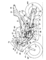
図1〜図8は本発明の第1実施例を示すものであり、図1は自動二輪車の側面図、図2は図1の2−2線拡大断面図、図3は図1の3矢示部拡大図、図4は図3の4矢視部、図5は図2の5矢示部拡大図、図6は自動クラッチ制御のメインルーチンを示すフローチャート、図7はクラッチ接続制御のサブルーチンを示すフローチャート、図8は第6変速段から第5変速段へのシフトダウン時の(エンジン回転数/後輪車速)の変化を示す図である。
1 to 8 show a first embodiment of the present invention. FIG. 1 is a side view of a motorcycle, FIG. 2 is an enlarged sectional view taken along line 2-2 in FIG. 1, and FIG. 3 is an arrow 3 in FIG. 4 is an enlarged view of the portion indicated by the arrow 4 in FIG. 3, FIG. 5 is an enlarged view of the portion indicated by the
先ず図1において、鞍乗り型車両である自動二輪車の車体フレームFは、前輪WFを軸支するフロントフォーク11を操向可能に支承するヘッドパイプ12と、該ヘッドパイプ12から後ろ下がりに延びる左右一対のメインフレーム13…と、ヘッドパイプ12および両メインフレーム13…の前部に溶接されてメインフレーム13…から下方に延びる左右一対のエンジンハンガ14…と、メインフレーム13…の後部から下方に延びる左右一対のピボットプレート15…と、後ろ上がりに延びて前記両メインフレーム13…の後部に連結される後部フレーム16とを備える。
First, in FIG. 1, a body frame F of a motorcycle, which is a saddle-ride type vehicle, includes a
前記両エンジンハンガ14…の下部、前記メインフレーム13…の中間部ならびにピボットプレート15…の上部および下部には、前部バンクBFおよび後部バンクBRを有してV型に構成される多気筒たとえば5気筒のエンジン本体17が支持される。
A multi-cylinder configured in a V shape with a front bank BF and a rear bank BR at the lower part of the
前記両ピボットプレート15…の上下方向中間部には、スイングアーム18の前端部が支軸19を介して揺動可能に支承されており、このスイングアーム18の後端部に後輪WRの車軸20が回転自在に支承される。
A front end portion of a
前記エンジン本体17に内蔵された歯車変速機47(図2参照)が備えるカウンタシャフト21からの動力は、チェーン伝動手段22を介して後輪WRに伝達されるものであり、該チェーン伝動手段22は、前記カウンタシャフト21に固定される駆動スプロケット23と、後輪WRに固定される被動スプロケット24と、それらのスプロケット23,24に巻掛けられる無端状のチェーン25とで構成される。
The power from the
前記スイングアーム18の前部には、リヤクッションユニット26の上端部が連結されており、このリヤクッションユニット26の下端部は、リンク機構27を介して前記両ピボットプレート15…の下部に連結される。
An upper end portion of a
エンジン本体17の前部および後部バンクBF,BRにおけるシリンダヘッド28F,28Rの上方には、エアクリーナ29が配置され、このエアクリーナ29の後方で前記エンジン本体17を上方から覆う燃料タンク30が前記後部フレーム16に支持される。また燃料タンク30の後方で後部フレーム16上にはライダーを座乗させるためのメインシート31が支持され、同乗者を乗せるためのピリオンシート32が前記メインシート31から後方に離れた位置で後部フレーム16に支持される。
An
ところでヘッドパイプ12の前方は、合成樹脂から成るフロントカウル36で覆われ、車体の前部両側が、前記フロントカウル36に連なる合成樹脂製のセンターカウル37で覆われ、エンジン本体17の一部を両側から覆う合成樹脂製のロアカウル38…がセンターカウル37に連設される。また後部フレーム16の後部はリヤカウル39で覆われ、前記燃料タンク30およびエアクリーナ29はカバー40で覆われ、前輪WFの上方を覆うフロントフェンダー41はフロントフォーク11に取付けられる。
By the way, the front of the
図2において、エンジン本体17のクランクケース42は、上下に2分割されており、自動二輪車の幅方向に沿う軸線を有するクランクシャフト43が該クランクケース42で回転自在に支承される。このクランクケース42内には、クランクシャフト43の大部分を収納するクランク室44と、そのクランク室44の後方側および下方側に位置する変速機室45とが、相互間に隔壁46を介在させるようにして形成される。
In FIG. 2, the
前記変速機室45には、常時噛合式の歯車変速機47が収納されるものであり、この歯車変速機47は、クランクシャフト16と平行な軸線を有する被動部材としてのメインシャフト48およびカウンタシャフト21間に、選択的な確立を可能とした複数変速段たとえば6段の第1速〜第6速歯車列G1〜G6が設けられて成るものであり、カウンタシャフト21は、クランクケース42で回転自在に支承されるようにしてクランクシャフト43よりも後方側に配置され、メインシャフト48は、クランクシャフト43およびカウンタシャフト21間に対応する部分でクランクケース42に回転自在に支承され、このメインシャフト48にはクランクシャフト43からの動力がクラッチ49を介して入力される。
The
メインシャフト48の一端は、クランクケース42において自動二輪車への搭載時に自動二輪車の進行方向右側となる右側壁50を貫通するものであり、メインシャフト48の一端側はボールベアリング51を介して前記右側壁50に支承される。またメインシャフト48の他端は、クランクケース42において自動二輪車への搭載時に自動二輪車の進行方向左側となる左側壁52に軸受メタル53を介して回転自在に支承される。カウンタシャフト21の一端は前記右側壁50にニードルベアリング54を介して回転自在に支承され、カウンタシャフト21の他端は前記左側壁52を貫通し、カウンタシャフト21の他端側および左側壁52間にはボールベアリング55が介装される。而して前記左側壁52からのカウンタシャフト21の突出端部に駆動スプロケット23が固定される。
One end of the
クランクシャフト43の一端部は、クランクケース42の右側壁を回転自在に貫通するものであり、このクランクシャフト43の一端部にはプライマリドライブギヤ56が固定され、このプライマリドライブギヤ56に噛合するプライマリドリブンギヤ57が、メインシャフト48の右側壁50からの突出部に相対回転を可能として装着され、プライマリドリブンギヤ57よりも外方でメインシャフト48に装着される前記クラッチ49のクラッチアウタ59に、前記プライマリドリブンギヤ57がダンパばね58を介して連結される。
One end of the
而してクラッチ49は、メインシャフト48に対する相対回転を可能とした前記クラッチアウタ59と、メインシャフト48との相対回転を不能としたクラッチインナ60と、クラッチアウタ59の内周に係合される複数枚の駆動摩擦板61…と、それらの駆動摩擦板61…間に挟まれるようにしてクラッチインナ60の外周に係合される複数枚の被動摩擦板62…と、相互に重合された駆動摩擦板61…および被動摩擦板62…の一端に対向してクラッチアウタ59内に収容されるとともにメインシャフト48に固定される受圧板63と、前記クラッチインナ60に結合されるレリーズ板64と、クラッチインナ60およびレリーズ板64を受圧板63に近接させる側に付勢するクラッチばね65とを備える。
Thus, the clutch 49 is engaged with the clutch outer 59 that can rotate relative to the
このようなクラッチ49は、レリーズ板64を前記クラッチばね65のばね力に抗して受圧板63側に駆動することによってクランクシャフト43およびメインシャフト48間の動力伝達が遮断され、またレリーズ板64を受圧板63側に押圧する力を開放したときには接続状態となり、クランクシャフト43の回転動力がメインシャフト48に伝達される。
In such a clutch 49, power transmission between the
ところで、メインシャフト48は中空の円筒状に形成されており、メインシャフト48の一端部に挿入されるロッド67の一端が前記レリーズ板64の中央部にスラストベアリング66を介して当接される。
Incidentally, the
またメインシャフト48内には、前記押圧棒67に一端部が連接される円筒状の伝達ロッド68と、該伝達ロッド68の他端部に一端部が同軸に連結される伝達ロッド69とが軸方向に移動可能として挿入されており、伝達ロッド68の一端に固定される押圧部材70が複数の球体71…を介して前記ロッド67の他端に連接される。而して、伝達ロッド68,69を軸方向に駆動することにより、レリーズ板64が軸方向に駆動され、それによりクラッチ49の接続・遮断状態が切換えられることになる。
A
前記伝達ロッド69の他端部は、メインシャフト48の他端から突出するとともにクランクケース42の左側壁52を軸方向移動自在に貫通するものであり、伝達ロッド69および左側壁52間には環状のシール部材72が介装される。
The other end of the
再び図1において、フロントフォーク11に連なる操向ハンドル73には、クラッチ49の接続・遮断状態を切換える油圧を車両運転者の操作に応じて発生する第1油圧発生手段74が配設され、車体フレームFのメインフレーム13においてエンジン本体17の近傍には第1油圧発生手段74とは独立してクラッチ49の接続・遮断状態を切換える油圧を車両の運転状態に応じて自動的に発生する第2油圧発生手段75が配設される。
In FIG. 1 again, the steering handle 73 connected to the
しかも前記クラッチ49を駆動する伝達ロッド69には、第1油圧発生手段74に連なる第1油圧室76に一面を臨ませる第1ピストン77と、第1油圧室76とは独立して第2油圧発生手段75に連なる第2油圧室78に一面を臨ませる第2ピストン79とが、連動、連結される。
In addition, the
第1油圧発生手段74は、操向ハンドル73の左グリップ80を握った左手で操作可能なクラッチレバー81と、クラッチレバー81の操作に応じて油圧を出力するクラッチマスタシリンダ82とから成るものであり、クラッチマスタシリンダ82から出力される油圧は第1導管83によって導かれる。
The first hydraulic pressure generating means 74 includes a
図3および図4において、第2油圧発生手段75は、自動クラッチ制御用マスタシリンダ84と、自動クラッチ制御用マスタシリンダ84を駆動する電動モータ85とを備える。
3 and 4, the second hydraulic pressure generating means 75 includes an automatic clutch
電動モータ85は、減速ギヤ機構を内蔵したギヤボックス86の下部に取付けられており、ギヤボックス86には、該ギヤボックス86の上部から上方に延びる第1取付け腕部87と、ギヤボックス86の上部から側方に延びるシリンダ支持部88と、シリンダ支持部88の先端部から上方に延びる第2取付け腕部89とが一体に設けられており、第1および第2取付け腕部87,88が、メインフレーム13に固着される支持部98,99に締結される。このギヤボックス86のメインフレーム13への取付け状態で電動モータ85は、その軸線を略鉛直方向に沿わせた姿勢となる。またギヤボックス86のシリンダ支持部88には、自動クラッチ制御用マスタシリンダ84が、その軸線を電動モータ85の軸線に直交させるようにして取付けられる。
The
ギヤボックス86の上部中央からは、電動モータ85の回転動力を減速して出力する出力軸90が電動モータ85と同軸にして上方に突出されており、この出力軸90の上部には回動アーム91の基端部が固定される。また回動アーム91の先端部には、出力軸90と平行な連結軸92が上方に向けて突設されており、自動クラッチ制御用マスタシリンダ84の一端から突出されるロッド93の先端部が、前記連結軸92に回動可能に連結される。而して電動モータ85を正逆方向に回転作動せしめることにより、回動アーム91が出力軸90の軸線まわりに回動し、それに応じて自動クラッチ制御用マスタシリンダ84が伸縮作動する。
From the upper center of the
自動クラッチ制御用マスタシリンダ84の他端には、該自動クラッチ制御用マスタシリンダ84から出力される油圧を導く第2導管95が回動可能なジョイント94を介して接続される。また自動クラッチ制御用マスタシリンダ84の中間部上面には、図示しないリザーバに接続されるリザーバ用接続管96が取付けられ、自動クラッチ制御用マスタシリンダ84の他端部上面には、自動クラッチ制御用マスタシリンダ84内からエアーを抜くためのエアー抜き管97が一体に設けられ、このエアー抜き管97は通常状態では閉塞される。
The other end of the automatic clutch
図5において、クランクケース42の左側壁52には、クラッチ49に対応した単一のクラッチ駆動手段100が配設されており、このクラッチ駆動手段100のハウジング99に、第1および第2ピストン77,79が、第1ピストン77を第2ピストン79で同心状に囲むようにして収容される。
In FIG. 5, a single clutch driving means 100 corresponding to the clutch 49 is disposed on the
ハウジング99は、クランクケース42の左側壁52に取付けられる支持ケース101、大シリンダ体102および小シリンダ体104で構成されるものであり、支持ケース101は、クランクケース42の左側壁52に閉塞端を対向させるようにして有底円筒状に形成されており、支持ケース101の閉塞端外面からは、前記左側壁52の外面に当接して締結される複数の脚部101a…が一体に当接され、支持ケース101は、前記左側壁52への締結状態で、歯車変速機47のメインシャフト48と同軸上に配置される。支持ケース101の閉塞端外面中央部には、前記左側壁52から突出される伝達ロッド69を摺動可能に挿通せしめるガイド筒部101bが一体に突設されており、伝達ロッド69は、ガイド筒部101bから支持ケース101内に突入される。
The
支持ケース101内には、円筒状の大シリンダ体102が嵌合される。この大シリンダ体102の中間部外周には半径方向外方に張り出す外向き鍔部102aが一体に設けられており、外向き鍔部102aが、支持ケース101の開口端に当接して複数のボルト103…により締結される。また大シリンダ体102の前記支持ケース101からの突出端部には、半径方向内方に張り出す内向き鍔部102bが一体に設けられる。
A cylindrical
大シリンダ体102内には、外方側を閉塞端とした有底円筒状の小シリンダ体104が液密に嵌合されており、小シリンダ体104の閉塞端外周部は、前記大シリンダ体102の内向き鍔部102bに内方側から当接し、複数のボルト118…によって内向き鍔部102bに締結される。この小シリンダ体104には、大シリンダ体102よりも小径である円筒状のシリンダ部104aが大シリンダ体102内に同軸に配置されるようにして一体に設けられる。
In the
第1ピストン77は、小シリンダ体104の閉塞端との間に第1油圧室76を形成するようにしてシリンダ部104aに摺動可能に嵌合される。また第2ピストン79は、リング状に形成されており、小シリンダ体104のシリンダ部104aおよび大シリンダ体102間に摺動可能に嵌合され、大シリンダ体102およびシリンダ部104a間で第2ピストン79および小シリンダ体104間に環状の第2油圧室78が形成される。
The
大シリンダ体79にはスライド部材105の外周が嵌合される。このスライド部105の中央部には、伝達ロッド69が嵌合、当接されており、スライド部材105および伝達ロッド69は一体的に作動する。またスライド部材105には、大シリンダ体79内を該スライド部材105で仕切ることがないように両面間にわたる貫通孔107が設けられる。さらに大シリンダ体102の内端部内周には、スライド部材105の離脱を阻止するための止め輪110が装着される。
The outer periphery of the
第1油圧室76とは反対側で第1ピストン77の中央部には連結凹部106が設けられており、スライド部材105の中央部に設けられた連結突部105aが、その先端部を連結凹部106の閉塞端に当接させ得るようにして連結凹部106に挿入される。また連結凹部106の閉塞端および連結突部105a間に通じるようにして軸方向に延びる溝106aが連結凹部106の内周に設けられる。さらにスライド部材105の外周部には第2ピストン79が当接可能であり、第1および第2ピストン77,79のいずれもが、その作動時にスライド部材105を押圧することが可能であり、第1および第2油圧室76,78には、第1および第2ピストン77,79をスライド部材105に当接させるだけの弱いばね力を発揮するばね108,109が収容される。
A connecting
小シリンダ体104の閉塞部には、第1油圧室76に通じる油路111を形成する接続管112が、その軸線を小シリンダ体104の半径方向に沿わせるようにして取付けられており、接続管112の外端は閉塞される。而して第1導管83に接続されるジョイント113が、第1導管83内を油路111に通じさせるようにして接続管112に装着される。またエア抜き管114が油路111に通じるようにして接続管112に装着されており、このエア抜き管114は通常時には閉塞される。
A connecting
また大シリンダ体102には、第2油圧室78に通じる油路115を形成する接続管116が、その軸線を大シリンダ体102の半径方向に沿わせるようにして取付けられており、接続管116の外端は閉塞される。而して第2導管95に接続されるジョイント117が、第2導管95内を油路115に通じさせるようにして接続管116に装着されている。
In addition, a connecting
したがって第1油圧発生手段74で発生した油圧は第1導管83を介して第1油圧室76に作用し、第1油圧室76の油圧増大に応じて第1ピストン77はスライド部材105を介して伝達ロッド69を押圧することになり、それによりクラッチ49が遮断状態となる。この際、第2油圧発生手段75側で油圧が発生していないときには、第2ピストン79は静止したままであり、スライド部材105は第2ピストン79から離反してスライドすることになる。また第2油圧発生手段75で発生した油圧は第2導管95を介して第2油圧室78に作用し、第2油圧室78の油圧増大に応じて第2ピストン79はスライド部材105を介して伝達ロッド69を押圧することになり、それによりクラッチ49が遮断状態となる。この際、第1油圧発生手段74側で油圧が発生していないときには、第1ピストン77は静止したままであり、スライド部材105は第1ピストン77から離反してスライドすることになる。
Accordingly, the hydraulic pressure generated by the first hydraulic pressure generating means 74 acts on the first
ところで、第2油圧発生手段75におけるで電動モータ85の作動は自動二輪車の運転状態に応じて、図6で示すように自動制御されるものであり、ステップS1では、シフトダウンを検知したか否かを判定する。シフトダウンを検知したときには、ステップS2に進み、電動モータ85を作動せしめて自動クラッチ制御用マスタシリンダ84から油圧を出力して第2ピストン79を作動せしめることにより、クラッチ49を遮断する。
By the way, the operation of the
次のステップS3では、歯車変速機47においてギヤ変速がなされた否かを判定し、ギヤ変速がなされていないときにはステップS4で一定時間が経過するか否かを判定し、一定時間経過後にステップS5で、電動モータ85を逆方向に作動せしめて自動クラッチ制御用マスタシリンダ84の油圧を解放し、第2油圧室78の油圧を解放することで第2ピストン79を戻らせてクラッチ49を接続状態とする。
In the next step S3, it is determined whether or not a gear shift has been performed in the
またステップS3でギヤ変速を確認したときには、ステップS6に進んでクラッチ接続制御処理を行うのであるが、このクラッチ接続制御処理は、図7で示すフローチャートに従って実行される。 When the gear shift is confirmed in step S3, the process proceeds to step S6 to perform the clutch connection control process. This clutch connection control process is executed according to the flowchart shown in FIG.
図7において、ステップS11,S12,S13では、変速段の検知、エンジン回転数NEの読込み、ならびに後輪車速VRWの読み込みを順次行うものであり、ステップS13では、後輪車速VRWの読み込みに代えて、カウンタシャフト21の回転数を読み込むようにしてもよい。
In FIG. 7, in steps S11, S12, and S13, the shift speed is detected, the engine speed NE is read, and the rear wheel vehicle speed VRW is sequentially read. In step S13, instead of reading the rear wheel vehicle speed VRW. Thus, the rotational speed of the
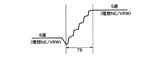
ステップS14では、(NE/VRW)もしくは(NE/カウンタシャフト21の回転数)を算出し、ステップS15では、シフトダウン前の変速段毎に予め設定されている所定時間をテーブルから読み込み、その後のステップS16で、エンジン回転数NEおよび後輪車速VRWのフィードバックによるクラッチ接続制御を行う。 In step S14, (NE / VRW) or (NE / number of rotations of countershaft 21) is calculated. In step S15, a predetermined time set in advance for each gear position before downshifting is read from the table, and thereafter In step S16, clutch connection control is performed by feedback of the engine speed NE and the rear wheel vehicle speed VRW.
このステップS16におけるクラッチ接続制御は、シフトダウン前の変速段に応じて定める所定時間の経過後に、ステップS14で算出した(NE/VRW)が、シフトダウン後の理想の(NE/VRW)に近づくように制御するものであり、たとえば第6変速段から第5変速段へのシフトダウン時には、図8で示すように、第6変速段に対応して予め設定されている所定時間T6経過後に第5変速段での理想の(NE/VRW)に達するように電動モータ85を微小駆動制御し、それによりクラッチ49の接続・遮断状態が繰り返される。
In the clutch connection control in step S16, (NE / VRW) calculated in step S14 approaches the ideal (NE / VRW) after downshifting after a predetermined time determined according to the gear position before downshifting. For example, at the time of downshift from the sixth gear to the fifth gear, for example, as shown in FIG. 8, after a predetermined time T6 preset corresponding to the sixth gear has elapsed, The
次にこの第1実施例の作用について説明すると、エンジンのクランクシャフト43と、歯車変速機47のメインシャフト48との間に介設されるクラッチ49の接続・遮断状態は、油圧を車両運転者の操作に応じて発生する第1油圧発生手段74の油圧発生に応じて切換えられるとともに、油圧を車両の運転状態に応じて自動的に発生する第2油圧発生手段75の油圧発生に応じて第1油圧発生手段74とは独立して切換えられるのであるが、クラッチ49には、第1油圧発生手段74に連なる第1油圧室76に一面を臨ませる第1ピストン77と、第1油圧室76とは独立して第2油圧発生手段75に連なる第2油圧室78に一面を臨ませる第2ピストン79とが連動、連結されている。
Next, the operation of the first embodiment will be described. The connection / disengagement state of the clutch 49 interposed between the
すなわち第1油圧発生手段74の油圧発生に応じた第1ピストン77の作動に応じてクラッチ49の接続・遮断状態を切換可能であるとともに、第2油圧発生手段75の油圧発生に応じて第1ピストン77とは独立した第2ピストン79の作動に応じてクラッチ49の接続・遮断状態を切換可能であり、運転者のクラッチ操作と、自動的なクラッチ制御とが相互に干渉することを防止して制御の簡素化を図ることができる。しかも作動油の交換時には第1および第2油圧発生手段74,75に連なる油圧経路のうち必要な油圧経路だけを交換することで作動油交換量を低減することができる。
That is, the connection / disconnection state of the clutch 49 can be switched according to the operation of the
またクラッチ49を駆動するための単一のクラッチ駆動手段100が備える支持ケース99に、第1および第2ピストン77,79が収容されているので、クラッチ49を駆動するクラッチ駆動手段100を第1および第2油圧発生手段74,75に共通に配置して、部品点数の低減を図るとともに、設置スペースの限られた車両であってもクラッチ駆動手段100を設置するスペースを容易に確保することができる。
Further, since the first and
しかも第1および第2ピストン77,79は、第1ピストン77を第2ピストン79が同心状に囲むようにしてハウジング99に収容されるので、第1および第2ピストン77,79を軸方向に並べたものと比べて、クラッチ駆動手段100が軸方向に大型化するのを防止することができる。
Moreover, the first and
さらに第1油圧発生手段74が、鞍乗り型である自動二輪車の操向ハンドル73側に配設され、第2油圧発生手段75がエンジン本体17の近傍で車体フレームFのメインフレーム13側に配設されるので、第2油圧発生手段75から第2ピストン79までの油圧経路を短縮することができ、油圧伝達時間を短縮することができるので、第2油圧発生手段75によるクラッチ制御の精度および応答性を高めることができる。
Further, the first hydraulic pressure generating means 74 is disposed on the steering handle 73 side of the saddle riding type motorcycle, and the second hydraulic pressure generating means 75 is disposed on the
上記第1実施例では、第2油圧発生手段75が、エンジン本体17の近傍で車体フレームFに設けられていたが、第2油圧発生手段75は、エンジン本体17の近傍であれば、エンジン本体17の左右両側のいずれか一方側、エンジン本体17の上下いずれか一方側、もしくはV型であるエンジン本体17の前部バンクBFおよび後部バンクBR間に配設されていてもよい。
In the first embodiment, the second hydraulic pressure generating means 75 is provided in the vehicle body frame F in the vicinity of the engine
図9は本発明の第2実施例を示すものであり、図1に対応する部分には同一の参照符号を付すだけで、詳細な説明は省略する。 FIG. 9 shows a second embodiment of the present invention. Parts corresponding to those in FIG. 1 are given the same reference numerals, and detailed description thereof is omitted.
クラッチ49(第1実施例参照)に対応した単一のクラッチ駆動手段120のハウジング119には、第1および第2ピストン122,123が軸方向に並んで収容される。
The first and
ハウジング119は、クランクケース42の左側壁52(第1実施例参照)に取付けられる支持ケース124、第1シリンダ体125および第2シリンダ体126で構成されるものであり、支持ケース124は、クランクケース42の左側壁52(第1実施例参照)に閉塞端を対向させるようにして有底円筒状に形成されており、支持ケース124の閉塞端外面に突設される複数の脚部124a…が前記左側壁52にボルト127…によって締結される。
The
第1シリンダ体125は、支持ケース124に嵌合される円筒状のシリンダ部125aと、支持ケース124とは反対側でシリンダ部125aの端部を閉じる端壁125bと、シリンダ部125aよりも大径に形成されて端壁125bの外周からシリンダ部125aと反対側に延びる円筒状のケース部125cとを一体に有する。また第2シリンダ体126は、外方側を閉塞端とした有底円筒状に形成されており、そのシリンダ部126aの外周が第1シリンダ体125のケース部125cに嵌合される。而して支持ケース124、第1シリンダ体および第2シリンダ体126は複数のボルト128…で結合される。
The
第1ピストン122は、第2シリンダ体126の閉塞端との間に第1油圧室129を形成するようにして第2シリンダ体126のシリンダ部126aの内周面に摺動可能に嵌合される。また第2ピストン123は、第1シリンダ体125の端壁125bとの間に第2油圧室130を形成するようにして第1シリンダ体125のシリンダ部125aに摺動可能に嵌合される。而して前記シリンダ部126aは本発明(請求項2)の第1のシリンダ部を構成し、また前記シリンダ部125aは本発明の(請求項2)の第2のシリンダ部を構成している。
The
支持ケース124内に突入される伝達ロッド69は、押圧ロッド131の一端部に嵌合、当接されており、この押圧ロッド131および伝達ロッド69は一体的に作動する。第2ピストン123の中央部には、押圧ロッド69と同軸の大嵌合孔132と、支持ケース124側に臨む環状の段部133を大嵌合孔132との間に形成する小嵌合孔134とが同軸に設けられており、押圧ロッド131は、前記段部133に当接する段部132aを外周に有して大嵌合孔132および小嵌合孔134を液密にかつ摺動可能に貫通する。また押圧ロッド131は、第1シリンダ体125における端壁125bの中央部を液密に且つ軸方向移動自在に貫通するものであり、押圧ロッド131の他端部は、第1ピストン122に嵌合、当接される。すなわち第1油圧室129とは反対側で第1ピストン122の中央部には連結凹部135が設けられており、押圧ロッド131の他端部は、その先端部を連結凹部135の閉塞端に当接させ得るようにして連結凹部135に挿入される。
The
而して第1および第2ピストン122,123は、いずれもその作動時に押圧ロッド131を介して伝達ロッド69を押圧することが可能であり、第1および第2油圧室129,130には、第1および第2ピストン122,123を押圧ロッド131に当接させるだけの弱いばね力を発揮するばね136,137が収容される。
Thus, both the first and
第2シリンダ体126の閉塞部には、第1実施例と同様の構造により、第1導管83が、第1油圧室129に通じさせるようにして接続され、第1シリンダ体125には、第1実施例と同様の構造により、第2導管95が第2油圧室130に通じるようにして接続される。
A
この第2実施例によれば、クラッチ駆動手段120のハウジング119に、第1および第2ピストン122,123が軸方向に並ぶようにして収容されるので、第1および第2ピストン77,79を同心状に配置した第1実施例と比べて、クラッチ駆動手段120の外径を小さくすることができるとともに必要作動油量を低減することができる。
According to the second embodiment, since the first and
また前述した第1および第2実施例のような機構を採用することで、運転者によるクラッチの接続・遮断操作に応じて、第2油圧発生手段75を作動せしめるように制御すると、運転者のクラッチ操作荷重を低減するようなクラッチアシスト制御を行うことが可能となる。 Further, by adopting the mechanism as in the first and second embodiments described above, if the control is performed so that the second hydraulic pressure generating means 75 is operated according to the clutch connecting / disconnecting operation by the driver, the driver's It is possible to perform clutch assist control that reduces the clutch operation load.
本発明の第3実施例として、図10で示すように、第2油圧発生手段75が、エンジン本体17から離反するようにして車体フレームFにおける後部フレーム16に取付けられるようにしてもよく、このようにすれば、エンジン本体17から放出される熱による影響が第2油圧発生手段75に及ぶことを回避することができる。
As a third embodiment of the present invention, as shown in FIG. 10, the second hydraulic pressure generating means 75 may be attached to the
以上、本発明の実施例を説明したが、本発明は上記実施例に限定されるものではなく、特許請求の範囲に記載された本発明を逸脱することなく種々の設計変更を行うことが可能である。 Although the embodiments of the present invention have been described above, the present invention is not limited to the above-described embodiments, and various design changes can be made without departing from the present invention described in the claims. It is.
17・・・・エンジン本体
48・・・・被動部材であるメインシャフト
49・・・・クラッチ
69・・・・伝達ロッド
73・・・・操向ハンドル
74・・・・第1油圧発生手段
75・・・・第2油圧発生手段
76,129・・・第1油圧室
77,122・・・第1ピストン
78,130・・・第2油圧室
79,123・・・第2ピストン
99,119・・・ハウジング
100,120・・・クラッチ駆動手段
102・・・大シリンダ体
104・・・小シリンダ体
105・・・スライド部材
125a・・第2のシリンダ部
125b・・壁
126a・・第1のシリンダ部
131・・・ロッド状のスライド部材
F・・・・・車体フレーム
17 ···
69 ...
102 ... Large cylinder body
104 ... Small cylinder body
105 ... Slide member
125a .. Second cylinder part
125b .. Wall
126a .. First cylinder part
131 ... Rod-shaped slide member F ... Body frame
Claims (6)
前記第1,第2ピストン(77,79)は、前記ハウジング(99)内で一方のピストン(77)を他方のピストン(79)が同心状に囲むように配置されていると共に、前記ハウジング(99)は、前記一方のピストン(77)の外周を内周面に摺動可能且つ液密に嵌合させると共に前記他方のピストン(79)の内周を外周面に摺動可能且つ液密に嵌合させる小シリンダ体(104)と、前記他方のピストン(79)の外周を内周面に摺動可能且つ液密に嵌合させる大シリンダ体(102)とを互いに同心状に且つ一体に備えており、
その大シリンダ体(102)の内周面には、前記第1,第2ピストン(77,79)とは別体に形成されて前記伝達ロッド(69)に連動、連結されるスライド部材(105)が摺動可能に嵌合され、
前記スライド部材(105)には前記第1,第2ピストン(77,79)が、各ピストン(77,79)からスライド部材(105)側への一方向にのみ動力伝達可能としてそれぞれ係合していることを特徴とする、車両のクラッチ制御装置。 A clutch (49) for switching the connection / disconnection state between the engine and the driven member (48), and a first oil pressure generating means for generating a hydraulic pressure for switching the connection / disconnection state of the clutch (49) according to the operation of the vehicle driver (74) and second hydraulic pressure generating means (automatically generating hydraulic pressure for switching the connection / disengagement state of the clutch (49) in accordance with the operating state of the vehicle independently of the first hydraulic pressure generating means (74)). 75), the first hydraulic chamber (76) connected to the first hydraulic pressure generating means (74), the first piston (77) facing one side, and the first hydraulic chamber (76) are independent of the second hydraulic pressure generation. A second piston (79) that faces the second hydraulic chamber (78) connected to the means (75), and each piston (77, 79) and the clutch (49) are provided between them in order to interlock and connect. Transmission rod (69) and both A clutch control apparatus for a vehicle comprising a housing (99) accommodating the piston (77, 79),
The first and second pistons (77, 79) are arranged so that one piston (77) concentrically surrounds the other piston (79) in the housing (99), and the housing ( 99) the outer periphery of the one piston (77) is slidable and liquid-tightly fitted on the inner peripheral surface, and the inner periphery of the other piston (79) is slidable and liquid-tight on the outer peripheral surface. The small cylinder body (104) to be fitted and the large cylinder body (102) to be fitted in a liquid-tight manner so that the outer circumference of the other piston (79) can slide on the inner circumferential surface are concentrically and integrally formed. Has
A slide member (105) is formed on the inner peripheral surface of the large cylinder body (102) separately from the first and second pistons ( 77, 79 ), and is linked to and connected to the transmission rod (69). ) Is slidably fitted,
The first and second pistons (77, 79) engage with the slide member (105) so that power can be transmitted only in one direction from the pistons (77, 79) to the slide member (105). A vehicle clutch control device.
前記ハウジング(99)は、前記第1ピストン(122)の外周を内周面に摺動可能且つ液密に嵌合させる第1のシリンダ部(126a)と、その第1のシリンダ部(126a)に対し同一軸線上に配列されて前記第2ピストン(123)の外周を内周面に摺動可能且つ液密に嵌合させる第2のシリンダ部(125a)と、その両シリンダ部(126a,125a)の相互間を遮断する壁(125b)とを備え、
前記第1,第2ピストン(122,123)とは別体に形成されて前記伝達ロッド(69)に連動、連結されるロッド状のスライド部材(131)が、前記壁(125b)と、前記クラッチ(49)寄りのピストン(123)とをそれぞれ摺動可能且つ液密に貫通しており、
前記スライド部材(131)には、前記壁(125b)の前後において前記第1,第2ピストン(122,123)が、各ピストン(122,123)からスライド部材(131)側への一方向にのみ動力伝達可能としてそれぞれ係合していることを特徴とする、車両のクラッチ制御装置。 A clutch (49) for switching the connection / disconnection state between the engine and the driven member (48), and a first oil pressure generating means for generating a hydraulic pressure for switching the connection / disconnection state of the clutch (49) according to the operation of the vehicle driver (74) and second hydraulic pressure generating means (automatically generating hydraulic pressure for switching the connection / disengagement state of the clutch (49) in accordance with the operating state of the vehicle independently of the first hydraulic pressure generating means (74)). 75), the first piston (122) that faces the first hydraulic chamber (129) connected to the first hydraulic pressure generating means (74), and the first hydraulic chamber (129) are independent of the first hydraulic chamber (129). A second piston (123) facing one surface to the second hydraulic chamber (130) connected to the means (75), and each piston (129, 130) and the clutch (49) are provided between them to interlock and connect. Transmission rod And 69), the clutch control apparatus for a vehicle comprising a housing (99) for accommodating the pistons (129, 130),
The housing (99) includes a first cylinder part (126a) in which the outer periphery of the first piston (122) is slidable and liquid-tightly fitted on an inner peripheral surface, and the first cylinder part (126a). The second cylinder part (125a) is arranged on the same axis and the outer periphery of the second piston (123) is slidable and liquid-tightly fitted to the inner peripheral surface, and both cylinder parts (126a, 126a, 125a) and a wall (125b) for blocking each other,
A rod-shaped slide member (131) that is formed separately from the first and second pistons (122, 123) and is linked and connected to the transmission rod (69) includes the wall (125b), The piston (123) near the clutch (49) is slidable and liquid-tightly penetrated,
In the slide member (131), the first and second pistons (122, 123) are arranged in one direction from the pistons ( 122, 123 ) to the slide member (131) side before and after the wall (125b). A clutch control device for a vehicle, characterized in that each of them is engaged so that only power can be transmitted.
Priority Applications (4)
| Application Number | Priority Date | Filing Date | Title |
|---|---|---|---|
| JP2005053936A JP4767555B2 (en) | 2005-02-28 | 2005-02-28 | Vehicle clutch control device |
| EP05028260A EP1696147B1 (en) | 2005-02-28 | 2005-12-22 | Clutch control assembly for a vehicle |
| DE602005019532T DE602005019532D1 (en) | 2005-02-28 | 2005-12-22 | Clutch control device for a motor vehicle |
| US11/360,402 US7478717B2 (en) | 2005-02-28 | 2006-02-24 | Clutch control assembly for vehicle |
Applications Claiming Priority (1)
| Application Number | Priority Date | Filing Date | Title |
|---|---|---|---|
| JP2005053936A JP4767555B2 (en) | 2005-02-28 | 2005-02-28 | Vehicle clutch control device |
Publications (3)
| Publication Number | Publication Date |
|---|---|
| JP2006234150A JP2006234150A (en) | 2006-09-07 |
| JP2006234150A5 JP2006234150A5 (en) | 2008-01-10 |
| JP4767555B2 true JP4767555B2 (en) | 2011-09-07 |
Family
ID=35781256
Family Applications (1)
| Application Number | Title | Priority Date | Filing Date |
|---|---|---|---|
| JP2005053936A Expired - Fee Related JP4767555B2 (en) | 2005-02-28 | 2005-02-28 | Vehicle clutch control device |
Country Status (4)
| Country | Link |
|---|---|
| US (1) | US7478717B2 (en) |
| EP (1) | EP1696147B1 (en) |
| JP (1) | JP4767555B2 (en) |
| DE (1) | DE602005019532D1 (en) |
Families Citing this family (15)
| Publication number | Priority date | Publication date | Assignee | Title |
|---|---|---|---|---|
| JP5047574B2 (en) * | 2006-09-28 | 2012-10-10 | 本田技研工業株式会社 | Clutch device |
| JP4724635B2 (en) * | 2006-10-06 | 2011-07-13 | 株式会社スペシャルパーツ武川 | Clutch device for motorcycle |
| JP5013813B2 (en) * | 2006-10-30 | 2012-08-29 | 本田技研工業株式会社 | Power unit for vehicle |
| JP4937696B2 (en) * | 2006-10-31 | 2012-05-23 | 本田技研工業株式会社 | Clutch operation assist device |
| JP4900700B2 (en) * | 2007-01-30 | 2012-03-21 | 本田技研工業株式会社 | Clutch control device |
| WO2009049580A1 (en) | 2007-10-15 | 2009-04-23 | Luk Lamellen Und Kupplungsbau Beteiligungs Kg | Slave cylinder and release system |
| DE102008061071B4 (en) | 2008-01-02 | 2018-09-20 | Schaeffler Technologies AG & Co. KG | Slave cylinder for a hydraulic clutch release system |
| JP5286101B2 (en) | 2008-11-26 | 2013-09-11 | ヤマハ発動機株式会社 | Friction clutch and vehicle equipped with the same |
| JP5474618B2 (en) * | 2010-03-11 | 2014-04-16 | 本田技研工業株式会社 | Clutch actuator mounting structure for internal combustion engine |
| DE102011104418A1 (en) * | 2010-06-29 | 2011-12-29 | Schaeffler Technologies Gmbh & Co. Kg | Actuation device for a friction clutch |
| ITBO20120611A1 (en) * | 2012-11-07 | 2014-05-08 | Ferrari Spa | CLUTCH FOR AUTOTRUPTION NORMALLY CLOSED AND WITH HYDRAULIC IMPLEMENTATION |
| US8745867B1 (en) * | 2013-01-14 | 2014-06-10 | Kit Masters | Modular viscous fan clutch system |
| JP6215780B2 (en) * | 2014-06-12 | 2017-10-18 | 本田技研工業株式会社 | Hydraulic clutch device |
| JP6578833B2 (en) * | 2015-09-08 | 2019-09-25 | スズキ株式会社 | Vehicle having an engine unit |
| JP6820404B2 (en) * | 2017-03-22 | 2021-01-27 | 川崎重工業株式会社 | vehicle |
Family Cites Families (12)
| Publication number | Priority date | Publication date | Assignee | Title |
|---|---|---|---|---|
| JPS5530125B2 (en) * | 1973-09-20 | 1980-08-08 | ||
| JPS58639A (en) * | 1981-06-23 | 1983-01-05 | Honda Motor Co Ltd | Release device of clutch |
| US4560049A (en) * | 1982-09-28 | 1985-12-24 | Honda Giken Kogyo Kabushiki Kaisha | Operation device for clutch master cylinder with means to adjust the play stroke of the clutch lever |
| JP2648873B2 (en) * | 1988-08-12 | 1997-09-03 | ヤマハ発動機株式会社 | Motorcycle clutch operating device |
| JP2874481B2 (en) * | 1992-09-30 | 1999-03-24 | スズキ株式会社 | Power assist device for vehicle clutch |
| JP3787959B2 (en) * | 1997-06-19 | 2006-06-21 | いすゞ自動車株式会社 | Clutch connection / disconnection device |
| US6148980A (en) * | 1998-01-07 | 2000-11-21 | Eaton Corporation | Force transmitting assembly |
| GB9921527D0 (en) | 1999-09-14 | 1999-11-17 | Automotive Prod France | Clutch actuators |
| JP3940266B2 (en) * | 2001-01-22 | 2007-07-04 | 株式会社エクセディ | Hydraulic mechanism for clutch operating system |
| JP2003294062A (en) * | 2002-04-03 | 2003-10-15 | Yamaha Motor Co Ltd | Engine brake control apparatus for motor bicycle |
| EP1422433B1 (en) | 2002-11-20 | 2007-08-15 | LuK Lamellen und Kupplungsbau Beteiligungs KG | Hydraulic system |
| EP1531279A1 (en) | 2003-11-11 | 2005-05-18 | Uwe Eisenbeis | Device for controlling slip in motorcycle clutches |
-
2005
- 2005-02-28 JP JP2005053936A patent/JP4767555B2/en not_active Expired - Fee Related
- 2005-12-22 DE DE602005019532T patent/DE602005019532D1/en active Active
- 2005-12-22 EP EP05028260A patent/EP1696147B1/en not_active Expired - Fee Related
-
2006
- 2006-02-24 US US11/360,402 patent/US7478717B2/en not_active Expired - Fee Related
Also Published As
| Publication number | Publication date |
|---|---|
| DE602005019532D1 (en) | 2010-04-08 |
| EP1696147A1 (en) | 2006-08-30 |
| US20060191766A1 (en) | 2006-08-31 |
| EP1696147B1 (en) | 2010-02-24 |
| US7478717B2 (en) | 2009-01-20 |
| JP2006234150A (en) | 2006-09-07 |
Similar Documents
| Publication | Publication Date | Title |
|---|---|---|
| JP4767555B2 (en) | Vehicle clutch control device | |
| JP4936693B2 (en) | Saddle riding vehicle | |
| EP2372196B1 (en) | Transmission system for vehicle | |
| AU2014200265B2 (en) | Clutch control device in power unit for vehicle | |
| JP2008138541A (en) | Engine with clutch actuator | |
| CA2607705C (en) | Clutch-manipulation assist device | |
| JP6715151B2 (en) | Clutch actuator | |
| JP6722823B2 (en) | Saddle type vehicle | |
| AU2014200373A1 (en) | Power unit for vehicle | |
| JP2017048908A (en) | Multistage transmission system | |
| JP4936805B2 (en) | Saddle riding vehicle | |
| JP6853691B2 (en) | Vehicle power unit | |
| JP6191078B2 (en) | Power unit for motorcycle | |
| JP7134328B2 (en) | saddle-riding vehicle | |
| JP2008044541A (en) | Vehicular power unit | |
| AU2014200330B2 (en) | Power unit for vehicle and four-wheeled vehicle | |
| JP6753897B2 (en) | Power unit | |
| US9103424B2 (en) | Vehicle driving force transmission structure | |
| JP6703644B2 (en) | Hydraulic valve unit, saddle type vehicle | |
| JP5907556B2 (en) | Shift control device for saddle riding type vehicle | |
| JP6727270B2 (en) | transmission | |
| JP7203945B2 (en) | Clutch lock structure | |
| JP2007269206A (en) | Vehicular power transmission | |
| WO2020170509A1 (en) | Hydraulic actuator structure and saddle type vehicle | |
| JP2013204788A (en) | Clutch operation adjusting device for vehicle |
Legal Events
| Date | Code | Title | Description |
|---|---|---|---|
| A521 | Request for written amendment filed |
Free format text: JAPANESE INTERMEDIATE CODE: A523 Effective date: 20071115 |
|
| A621 | Written request for application examination |
Free format text: JAPANESE INTERMEDIATE CODE: A621 Effective date: 20071115 |
|
| A131 | Notification of reasons for refusal |
Free format text: JAPANESE INTERMEDIATE CODE: A131 Effective date: 20100519 |
|
| A977 | Report on retrieval |
Free format text: JAPANESE INTERMEDIATE CODE: A971007 Effective date: 20100520 |
|
| A521 | Request for written amendment filed |
Free format text: JAPANESE INTERMEDIATE CODE: A523 Effective date: 20100720 |
|
| A131 | Notification of reasons for refusal |
Free format text: JAPANESE INTERMEDIATE CODE: A131 Effective date: 20101215 |
|
| A521 | Request for written amendment filed |
Free format text: JAPANESE INTERMEDIATE CODE: A523 Effective date: 20110127 |
|
| A01 | Written decision to grant a patent or to grant a registration (utility model) |
Free format text: JAPANESE INTERMEDIATE CODE: A01 Effective date: 20110608 |
|
| A01 | Written decision to grant a patent or to grant a registration (utility model) |
Free format text: JAPANESE INTERMEDIATE CODE: A01 |
|
| A61 | First payment of annual fees (during grant procedure) |
Free format text: JAPANESE INTERMEDIATE CODE: A61 Effective date: 20110615 |
|
| R150 | Certificate of patent or registration of utility model |
Free format text: JAPANESE INTERMEDIATE CODE: R150 |
|
| FPAY | Renewal fee payment (event date is renewal date of database) |
Free format text: PAYMENT UNTIL: 20140624 Year of fee payment: 3 |
|
| LAPS | Cancellation because of no payment of annual fees |