JP4762665B2 - Body frame structure - Google Patents
Body frame structure Download PDFInfo
- Publication number
- JP4762665B2 JP4762665B2 JP2005303438A JP2005303438A JP4762665B2 JP 4762665 B2 JP4762665 B2 JP 4762665B2 JP 2005303438 A JP2005303438 A JP 2005303438A JP 2005303438 A JP2005303438 A JP 2005303438A JP 4762665 B2 JP4762665 B2 JP 4762665B2
- Authority
- JP
- Japan
- Prior art keywords
- vehicle body
- front side
- frame
- width direction
- crushing
- Prior art date
- Legal status (The legal status is an assumption and is not a legal conclusion. Google has not performed a legal analysis and makes no representation as to the accuracy of the status listed.)
- Expired - Fee Related
Links
Images


Landscapes
- Body Structure For Vehicles (AREA)
Description
本発明は、フロントサイドフレームの先端部にクラッシャブルゾーンを充分に確保することができない場合であっても、衝突時の衝撃エネルギを効率よく吸収することのできる車体フレーム構造に関する。 The present invention relates to a vehicle body frame structure capable of efficiently absorbing impact energy at the time of collision even when a crushable zone cannot be sufficiently secured at the front end portion of a front side frame.
従来、自動車等の車両におけるエンジンルームには、左右のフロントホイールエプロンに沿って前後方向に延設されたフロントサイドフレームが対向配設されており、この両フロントサイドフレームに、エンジンや動力伝達系の諸装置であるパワートレインが支持されている。 Conventionally, a front side frame extending in the front-rear direction along the left and right front wheel aprons is opposed to an engine room in a vehicle such as an automobile, and the engine and power transmission system are opposed to both front side frames. Powertrain, which is a variety of devices, is supported.
この両フロントサイドフレームの先端はバンパビーム等のクロス部材で連結されており、前面衝突時の衝撃荷重は、クロス部材を介してフロントサイドフレームに伝達される。フロントサイドフレームは軸圧潰により変形して衝撃エネルギを吸収すると共に、衝撃荷重をフロントサイドフレームに連続するリヤフレームやフロントピラー等のサイドストラクチャへ分散させることで、キャビン(車室)への衝撃荷重の伝達を阻止し、乗員を保護する。 The front ends of both front side frames are connected by a cross member such as a bumper beam, and the impact load at the time of a frontal collision is transmitted to the front side frame via the cross member. The front side frame is deformed by axial crushing to absorb impact energy, and the impact load is distributed to the side structures such as the rear frame and front pillar that are continuous with the front side frame, so that the impact load to the cabin (vehicle compartment) To prevent the transmission of passengers and protect passengers.
この場合、フロントサイドフレームの先端部にクラッシャブルゾーンが充分に確保されていないと、その後方に連続するサイドフレーム部分の突っ張り作用により衝撃荷重がキャビン側へ伝達されてしまう不都合がある。 In this case, if the crushable zone is not sufficiently secured at the front end portion of the front side frame, there is a problem that the impact load is transmitted to the cabin side due to the stretching action of the side frame portion continuous behind the front side frame.
その対策として、例えば特許文献1(特開2003−312534号公報)には、フロントサイドフレームの前端部と、それに内装するリンフォースとに、要求特性に応じて脆弱部を適宜形成し、フロントサイドフレームの前端に衝突荷重が入力されたとき、フロントサイドフレームの前端部に形成した脆弱部を軸圧潰させると共に、これに誘発されてリンフォースの脆弱部も蛇腹状の変形モードで軸圧潰させて衝突エネルギを吸収する技術が開示されている。 As a countermeasure, for example, in Patent Document 1 (Japanese Patent Laid-Open No. 2003-31534), a fragile portion is appropriately formed in the front end portion of the front side frame and the reinforcement housed in the front side frame according to required characteristics. When a collision load is input to the front end of the frame, the weakened portion formed at the front end of the front side frame is axially crushed, and the weakened portion of the reinforcement is also axially crushed in an accordion-like deformation mode. A technique for absorbing collision energy is disclosed.
特許文献1に開示されている技術では、リンフォースと脆弱部とを組み合わせることで、比較的短いクラッシャブルゾーンであっても、衝撃エネルギを吸収することが可能となる。
In the technique disclosed in
又、特許文献2(特開2003−312549号公報)には、フロントサイドフレームの後端下側に、フロアパネルの下面に接合されているサイドメンバエクステンションの前端を嵌合し、このサイドメンバエクステンションを中空断面のアウタ材と、内部に配設したリンフォースとで構成し、このアウタ材とリンフォースとの各屈曲モード波形のピーク数を互いに異なる素数に設定した技術が開示されている。 In Patent Document 2 (Japanese Patent Laid-Open No. 2003-312549), the front end of the side member extension joined to the lower surface of the floor panel is fitted to the lower side of the rear end of the front side frame. Is composed of an outer material having a hollow cross section and a reinforcement disposed inside, and a technique is disclosed in which the number of peaks of each bending mode waveform of the outer material and the reinforcement is set to different prime numbers.
特許文献2に開示されている技術では、アウタ材とリンフォースとの各屈曲モード波形のピーク数を異なる素数で設定したので、フロントサイドフレームのクラッシャブルゾーンが比較的短く、衝撃エネルギを充分に吸収することができない場合であっても、サイドメンバエクステンションに設けられているアウタ材とリンフォースとがそれぞれ独立して変形することで衝撃エネルギを吸収させることができる。
しかし、特許文献1に記載されている技術では、フロントサイドフレームをアウタ材とリンフォースとの二重構造としなければならず、構造が複雑化し製造コストが高くなってしまう問題がある。
However, the technique described in
特許文献2に開示されている技術も同様に、サイドメンバエクステンションをアウタ材とリンフォースとの二重構造としなければならず、構造が複雑化し製造コストが高くなってしまう問題がある。
Similarly, the technique disclosed in
本発明は、上記事情に鑑み、フロントサイドフレームの端部にクラッシャブルゾーンを充分に確保することが困難な構造であっても、フレーム構造を複雑化することなく、衝突時の衝撃エネルギを充分に吸収することが可能で、製造コストの低減を図ることのできる車体フレーム構造を提供することを目的とする。 In view of the above circumstances, the present invention has sufficient impact energy at the time of collision without complicating the frame structure even if it is difficult to sufficiently secure a crushable zone at the end of the front side frame. It is an object of the present invention to provide a vehicle body frame structure that can be absorbed into the vehicle body and can reduce manufacturing costs.
上記目的を達成するため本発明は、車体幅方向両側に車体の前後方向へ延出する一対のサイドフレームが設けられ、上記サイドフレームの先端がクロス部材を介して連結されており、上記サイドフレームの端部に、衝突時に軸圧潰させて衝撃エネルギを吸収する第1部材が設けられ、該第1部材に連続して断面強度の高い第2部材が設けられている車体フレーム構造において、上記第1部材と第2部材との結合部が車体幅方向中心軸に直交する軸線に対して車体幅方向内側から外側に向けて斜め後方へ後退するテーパ状に傾斜されていることを特徴とする。
In order to achieve the above object, according to the present invention, a pair of side frames extending in the front-rear direction of the vehicle body are provided on both sides in the vehicle body width direction, and the ends of the side frames are connected via a cross member. In the vehicle body frame structure, a first member that absorbs impact energy by axial crushing at the time of a collision is provided at an end of the vehicle body, and a second member having a high cross-sectional strength is provided continuously to the first member. A connecting portion between the first member and the second member is inclined in a taper shape that recedes obliquely rearward from the inner side to the outer side in the vehicle width direction with respect to an axis perpendicular to the central axis in the vehicle width direction .
本発明によれば、軸圧潰を促進させる第1部材と断面強度の高い第2部材とをテーパ状に傾斜させて結合したので、第2部材に入力される衝撃荷重は結合部の先端側が早く、後端側が遅れて到達する。その結果、結合部の先端側と後端側とで入力荷重がアンバランスとなり、第2部材に曲げモーメントが発生し、そのときのモーメント荷重により衝撃エネルギを吸収することができる。従って、フロントサイドフレームの端部にクラッシャブルゾーンを充分に確保することが困難な構造であっても、衝突時の衝撃エネルギを充分に吸収することができる。又、結合部を傾斜させただけの簡単な構造であるため、製造コストの低減を図ることができる。 According to the present invention, since the first member that promotes axial crushing and the second member having high cross-sectional strength are joined while being inclined in a taper shape, the impact load input to the second member is quicker at the distal end side of the joining portion. The rear end side arrives with a delay. As a result, the input load is unbalanced between the front end side and the rear end side of the coupling portion, a bending moment is generated in the second member, and impact energy can be absorbed by the moment load at that time. Therefore, even when it is difficult to sufficiently secure the crushable zone at the end of the front side frame, the impact energy at the time of collision can be absorbed sufficiently. Moreover, since the structure is a simple structure in which the coupling portion is inclined, the manufacturing cost can be reduced.
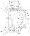
以下、図面に基づいて本発明の一形態を説明する。図1〜図5に本発明の第1形態を示す。図1、図2は車体前部の車体フレーム構造を示し、図1は概略平面図、図2は概略側面図である。 Hereinafter, an embodiment of the present invention will be described with reference to the drawings. 1 to 5 show a first embodiment of the present invention. 1 and 2 show a vehicle body frame structure at the front of the vehicle body, FIG. 1 is a schematic plan view, and FIG. 2 is a schematic side view.
同図の符号11は車体前部に設けられたエンジンルームであり、このエンジンルーム11の後部に、エンジンルーム11とキャビン14とを区画するトーボード15が配設されている。又、エンジンルーム11の車体幅方向両側に、閉断面形状に形成された互いに平行な一対のフロントサイドフレーム12が配設されている。尚、この各フロントサイドフレーム12の後部はトーボード15の傾斜に沿って下方且つ後方へ延出され、フロアパネルの車体幅方向両側に配設されているサイドシル(何れも図示せず)の前端部に各々連結されている。
又、両フロントサイドフレーム12の前端部間がフロントクロスメンバ或いはバンパビーム等のクロス部材13を介して互いに結合されている。更に、トーボード15の前方に、フロントサスペンション(図示せず)を支持するサスペンションクロスメンバ16が配設され、このサスペンションクロスメンバ16の両側が、各フロントサイドフレーム12の後部に各々連結されている。
The front end portions of both
エンジンルーム11内には、エンジン本体17とトランスミッション18とが結合して構成されたパワーユニット19が搭載されている。尚、本形態ではエンジン本体17として直列エンジンが示されており、パワーユニット19はエンジンルーム11に横置きに載置されている。又、パワーユニット19の車体幅方向両側が、各フロントサイドフレーム12に対し、マウントブラケット20を介して支持固定され、又、略中央後部がサスペンションクロスメンバ16に他のマウントブラケット(図示せず)を介して支持固定されている。尚、符号21はラジエータユニットである。
In the
フロントサイドフレーム12の後部は、サスペンションクロスメンバ16によって補剛されており、従って、フロントサイドフレーム12のクラッシャブルゾーンは、少なくとも先端部からサスペンションクロスメンバ16の取付け部位までの領域Z1となる。この場合、本形態のようにパワーユニット19が横置き配列では、フロントサスペンションから車体前部へのオーバハングが少ないため、クラッシャブルゾーンを比較的長く確保することが難しい。特に、フロントサイドフレーム12にてマウントブラケット20を介してパワーユニット19を支持する構造では、マウントブラケット20から先端部までの間がクラッシャブルゾーンの領域Z2となり、クラッシャブルゾーンは更に狭くなってしまう。尚、本形態では、領域Z2をクラッシャブルゾーンとしており、従って、以下においては、領域Z2をクラッシャブルゾーンZ2と読み換えて説明する。
The rear part of the
フロントサイドフレーム12は、断面強度の高い第2部材としてのメインフレーム部12aと、前面衝突時の衝撃荷重で軸圧潰が誘発される第1部材としての圧潰部12bとを備えている。圧潰部12bはクラッシャブルゾーンZ2とほぼ同じ領域に設定されていると共に、圧潰部12bの後端とメインフレーム部12aの先端との結合部である接合面12cが、車体幅方向内側から外側へ向けて斜め後方へ後退する斜面状に形成されている。尚、図3には車体幅方向左側のフロントサイドフレーム12が記載されている。又、図1(a),(b)に拡大して示すように、接合面12cの、車体幅方向中央を通る前後軸に直交する軸線Yに対する傾斜角度θは、5〜30°程度に設定することが望ましい。
The
従って、圧潰部12bの先端からメインフレーム部12aに衝撃荷重Fが伝達されるときの距離は、メインフレーム部12aの内側が短く、外側へ移行するに従い長くなる。
Accordingly, the distance when the impact load F is transmitted from the tip of the crushing
圧潰部12bは、軟鋼板、或いはアルミニュウム板など、メインフレーム部12aよりも剛性が低く、前面衝突時の衝撃荷重により軸圧潰が促進されるような材質を有している。尚、圧潰部12bは板厚を薄くすることで軸圧潰を促進させるような構造としても良い。
The crushing
本形態では、フロントサイドフレーム12がテーラードブランク材を用いて形成されている。テーラードブランク材は、板金加工後のメインフレーム部12aと圧潰部12bとに対応する位置に、接合面12cを境界として鋼板のブランク材と、軟鋼板やアルミニュウム板などの低剛性ブランク材とが接合されて形成されている。
In this embodiment, the
このような構成において、車両が前面衝突すると、その衝撃荷重Fが、フロントサイドフレーム12の先端を連結するクロス部材13を介して、両フロントサイドフレーム12の前端部に入力される。この左右のフロントサイドフレーム12の先端はクロス部材13によって連結されているため、衝撃荷重Fが入力されても、その反力で車体幅方向の内側或いは外側へ屈曲することはなく、衝撃荷重Fがフロントサイドフレーム12に対して軸方向に沿って伝達される。
In such a configuration, when the vehicle collides frontward, the impact load F is input to the front end portions of both
すると、図4に示すように、フロントサイドフレーム12のクラッシャブルゾーンZ2に設けられている圧潰部12bが蛇腹状に軸圧潰されて衝撃エネルギが吸収される。この圧潰部12bは低剛性材で形成されているため、軸圧潰が促進され、更に、前面衝突時の衝撃荷重Fが比較的小さい場合は、圧潰部12bの軸圧潰のみで衝撃エネルギを吸収することができる。
Then, as shown in FIG. 4, the crushing
一方、前面衝突時の衝撃荷重Fが比較的大きく、圧潰部12bの軸圧潰のみでは衝撃エネルギが充分に吸収しきれない場合、残りの衝撃荷重Fは圧潰部12bを介してメインフレーム部12a側へ伝達される。
On the other hand, when the impact load F at the time of the frontal collision is relatively large and the impact energy cannot be sufficiently absorbed only by the axial crushing of the crushing
圧潰部12bとメインフレーム部12aとの接合面12cは、車体幅方向内側から外側へ向けて斜め後方へ後退するテーパ状に形成されており、衝撃荷重Fの伝達距離は、内側が短く外側が長くなる。従って、衝撃荷重Fは、先ず、メインフレーム部12aの接合面12cの先端部である内側に先に到達し、それより遅れて接合面12cの外側に到達する。このように、メインフレーム部12aの内側に衝撃荷重Fが最初に入力されるため、メインフレーム部12aの内外で入力荷重がアンバランスとなり、メインフレーム部12aに曲げモーメントが発生する。
The
この場合、上述したように、左右のフロントサイドフレーム12の先端面はクロス部材13で連結されているため、両フロントサイドフレーム12の先端面が車体幅方向内側へ入り込むことはない。従って、図5に示すように、この曲げモーメントによるモーメント荷重が、メインフレーム部12a内側の比較的強度の弱い部分に集中し、この集中する部分を起点Pとして、メインフレーム部12aの中途が車体幅方向外側へ張り出すように屈曲変形される。そして、このメインフレーム部12aの屈曲変形により衝撃エネルギが吸収される。
In this case, as described above, since the front end surfaces of the left and right front side frames 12 are connected by the
尚、起点Pは、メインフレーム部12aの内側の中途に脆弱部を予め形成することで、発生部位を特定するようにしておいても良い。更に、フロントサイドフレーム12に固設されているマウントブラケット20は、このマウントブラケット20をフロントサイドフレーム12に締結するねじ部が剪断されるような脆弱部を形成し、或いはマウントブラケット20に破壊が促進されるような脆弱部を形成しておくことで、メインフレーム部12aの屈曲変形を阻害しないで、破壊が促進されるようにする。
In addition, the origin P may be made to identify the generation | occurrence | production site | part by forming a weak part previously in the middle inside the
このように、本形態では、衝撃荷重Fが比較的大きく、圧潰部12bの軸圧潰では衝撃エネルギが充分に吸収されない場合であっても、メインフレーム部12aを屈曲変形させることで、残りの衝撃エネルギを充分に吸収させることができるので、キャビン14への衝撃荷重の伝達が阻止され、乗員を有効に保護することができる。
Thus, in this embodiment, even when the impact load F is relatively large and the impact energy is not sufficiently absorbed by the axial crushing of the crushing
又、メインフレーム部12aの起点Pを車体幅方向外側へ屈曲変形させるようにしたので、パワーユニット19が横置きに配列されている場合であっても、起点Pがパワーユニット19から離れる方向へ変形するので、起点Pがエンジン本体17やトランスミッション18などに緩衝して屈曲変形が阻害されてしまうことがない。
Further, since the starting point P of the
尚、起点Pが車体幅方向内側へ移動してもエンジン本体17やトランスミッション18などと緩衝しない場合は、接合面12cの傾斜を、本形態とは逆方向へに形成して、メインフレーム部12aを内側へ屈曲変形させるようにしても良い。更に、メインフレーム部12aと圧潰部12bとを別体で形成する場合は、両部材12a,12bの接合面12cにフランジを形成し、このフランジをボルト締めして結合するようにしても良い。
If the starting point P moves inward in the vehicle body width direction and does not buffer with the
又、図6に本発明の第2形態を示す。図6(a)はフロントサイドフレームの要部分解斜視図、図6(b)はフロントサイドフレームの要部斜視図である。 FIG. 6 shows a second embodiment of the present invention. 6A is an exploded perspective view of the main part of the front side frame, and FIG. 6B is a perspective view of the main part of the front side frame.
上述した第1形態では、フロントサイドフレーム12をテーラードブランク材を用いて形成したが、本形態によるフロントサイドフレーム26は、断面ハット形状に形成したインナフレーム26a、アウタフレーム26b、及び第1部材としての圧潰部26cの3部品で形成されている。尚、アウタフレーム26b、及びこれに対応するインナフレーム26aとで形成された閉断面形状が断面強度の高い第2部材として機能する。
In the first embodiment described above, the
インナフレーム26aは比較的浅い溝深さでフロントサイドフレーム26の全長にわたって形成されている。従って、その前端はクロス部材13(図1参照)に連結されている。
The inner frame 26a is formed over the entire length of the
一方、このインナフレーム26aにモナカ合わせで接合されるアウタフレーム26bは比較的深い溝深さを有している。更に、このアウタフレーム26bの先端がクラッシャブルゾーンZ2付近でカットされている。又、このアウタフレーム26bのカットされた部位から露呈されているインナフレーム26aの先端に、アウタフレーム26bと同一断面形状の圧潰部26cが配設され、この圧潰部26cとインナフレーム26aとがモナカ合わせで接合されている。 On the other hand, the outer frame 26b joined to the inner frame 26a by monaca alignment has a relatively deep groove depth. Further, the tip of the outer frame 26b is cut in the vicinity of the crushable zone Z2. Further, a crushing portion 26c having the same cross-sectional shape as the outer frame 26b is disposed at the tip of the inner frame 26a exposed from the cut portion of the outer frame 26b. The crushing portion 26c and the inner frame 26a are connected to the monaca. They are joined together.
尚、図6には、車体幅方向左側のフロントサイドフレーム26のみが記載されており、車体幅方向右側のフロントサイドフレーム26が省略されているが、車体幅方向右側のフロントサイドフレーム26は、車体幅方向左側のフロントサイドフレーム26と対称に形成されている。
In FIG. 6, only the
圧潰部26cは軟鋼板やアルミニュウム板など、メインフレーム部12aよりも剛性の低い材質で形成し、或いは板厚の薄い鋼板を用いて形成することで剛性が低下されている。又、アウタフレーム26bの先端の結合部である接合面26dと、これに接合する圧潰部26c後端の接合面26eは、第1形態と同様、車体幅方向内側から外側へ向けて斜め後方へ後退するテーパ状に形成されている。尚、両接合面26d,26eはビーム溶接などの溶接手段を介して溶接されている。
The crushing portion 26c is made of a material having a lower rigidity than the
このような構成では、車体幅方向左右に配設されているフロントサイドフレーム26の先端に衝撃荷重Fが入力されると、この両フロントサイドフレーム26の先端がクロス部材13を介して連結されているため、車体幅方向内側或いは外側へ屈曲することはなく、圧潰部26c、及びこれに接合されているインナフレーム26aの先端部が、軸圧潰される。
In such a configuration, when an impact load F is input to the front ends of the front side frames 26 arranged on the left and right in the vehicle body width direction, the front ends of both front side frames 26 are connected via the
そして、圧潰部26cの後端とアウタフレーム26bの先端との接合面26d,26eに衝撃荷重Fが到達すると、接合面26d,26eが車体幅方向内側から外側へ向けて斜め後方へ後退するテーパ状に形成されているため、接合面26d,26eの内側に最初に衝撃荷重Fが入力される。そのため、アウタフレーム26bの内外で入力荷重がアンバランスとなり、インナフレーム26aに曲げモーメントが発生する。この曲げモーメントによるモーメント荷重は、インナフレーム26aの比較的強度の弱い部分に集中し、この集中する部分を起点として、フロントサイドフレーム26の中途が車体幅方向外側へ屈曲変形され、この屈曲変形により衝撃エネルギが吸収される。
When the impact load F reaches the joint surfaces 26d and 26e between the rear end of the crushing portion 26c and the front end of the outer frame 26b, the joint surfaces 26d and 26e taper backward from the vehicle width direction inner side toward the outer side. Therefore, the impact load F is first input inside the joint surfaces 26d and 26e. Therefore, the input load is unbalanced inside and outside the outer frame 26b, and a bending moment is generated in the inner frame 26a. The moment load due to this bending moment is concentrated in a relatively weak portion of the inner frame 26a, and the middle of the
このように、本形態では、インナフレーム26aを基材とし、このインナフレーム26aに、アウタフレーム26bと圧潰部26cとをモナカ合わせで接合することで、フロントサイドフレーム26を形成するようにしたので、圧潰部26cの位置決め、及び接合が容易となり、製造工数を削減することができる。又、製造時においては、圧潰部26cのみを簡単に設計変更することができるため、車両毎の特性に応じて最適な圧潰部26cの板厚、材質を選択することができ、製品の高い信頼性を得ることができる。
As described above, in this embodiment, the inner side frame 26a is used as a base material, and the outer side frame 26b and the crushing portion 26c are joined to the inner frame 26a by the monaca to form the
又、図7に本発明の第3形態によるフロントサイドフレームの要部斜視図を示す。尚、図には、車幅方向左側のフロントサイドフレーム31のみが記載されいるが、車体幅方向右側のフロントサイドフレームは、車体幅方向左側のフロントサイドフレーム31と対称に形成されている。又、このフロントサイドフレーム31は、第1形態のフロントサイドフレーム12に代えて適用するものであり、フロントサイドフレーム31以外の構成は、第1形態と同様である。
FIG. 7 is a perspective view showing a main part of a front side frame according to the third embodiment of the present invention. Although only the
本形態によるフロントサイドフレーム31は、閉断面形状に形成された第2部材としての断面強度の高いメインフレーム部32と第1部材としての圧潰部33とを別体で形成し、メインフレーム部32の先端部に圧潰部33の後端部を嵌入させてボルト締めしたものである。尚、メインフレーム部32、圧潰部33の材質、板厚は、上述した第1形態のメインフレーム部12a、圧潰部12bと同一である。
The
又、メインフレーム部32の前部と、これに嵌入される圧潰部33の後端部とのオーバラップ部34のインナ34aとアウタ34bとにインナ挿通孔35aとアウタ挿通孔35bとが上下2段に各々穿設されている。
In addition, an inner insertion hole 35a and an outer insertion hole 35b are vertically connected to an inner portion 34a and an outer portion 34b of an
図7(b)に示すように、インナ挿通孔35aとアウタ挿通孔35bとは、車体前後方向でオフセットされており、圧潰部12bの内面の、インナ挿通孔35aとアウタ挿通孔35bとに対応する位置にウエルドナット36が溶接されている。
As shown in FIG. 7B, the inner insertion hole 35a and the outer insertion hole 35b are offset in the longitudinal direction of the vehicle body, and correspond to the inner insertion hole 35a and the outer insertion hole 35b on the inner surface of the crushing
組付けに際しては、閉断面形状の圧潰部33の後端を、同じく閉断面形状のメインフレーム部32の先端に嵌入し、メインフレーム部32と圧潰部33とに各々穿設されているインナ挿通孔35a、及びアウタ挿通孔35bを位置合わせする。そして、この各挿通孔35a,35bに外方からボルト37を挿通し、このボルト37をウエルドナット36に螺入させて、メインフレーム部32と圧潰部33とを締結する。
When assembling, the rear end of the crushing
その際、インナ挿通孔35aに挿通されたボルト37と、アウタ挿通孔35bに挿通されたボルト37とが車体前後方向でオフセットされているため、両挿通孔35a,35bを結ぶオーバラップ部34上の外周面が、車体幅方向内側から外側へ向けて斜め後方へ後退するテーパ状の結合部となっている。尚、車幅方向左右に配設されているフロントサイドフレーム31の先端は、クロス部材13(図1参照)で互いに連結されている。
At that time, since the
このような構成において、前面衝突時の衝撃荷重Fが、クロス部材13を介して、左右のフロントサイドフレーム31に入力されると、圧潰部33が蛇腹状に軸圧潰されて衝撃エネルギが吸収される。そして、この圧潰部33の軸圧潰のみでは衝撃エネルギが充分に吸収しきれないと、衝撃荷重Fが、ボルト37を介してメインフレーム部32側へ伝達される。このボルト37を挿通するインナ挿通孔35aとアウタ挿通孔35bとは、車体前後方向でオフセットされているため、衝撃荷重Fの伝達距離は、インナ挿通孔35aに挿通されているボルト37の位置が、アウタ挿通孔35bに挿通されているボルト37の位置よりも短い。
In such a configuration, when the impact load F at the time of a frontal collision is input to the left and right front side frames 31 via the
従って、衝撃荷重Fは、先ず、インナ挿通孔35aに挿通されているボルト37に到達し、ある遅れを有してアウタ挿通孔35bに挿通されているボルト37に到達する。
Accordingly, the impact load F first reaches the
その結果、メインフレーム部32の先端には衝撃荷重Fがオフセット状態で入力されるため、メインフレーム部32の内外で入力荷重がアンバランスとなり、オーバラップ部34に曲げモーメントが発生する。そして、この曲げモーメントによるモーメント荷重が、メインフレーム部32内側の比較的強度の弱い部分に集中し、そこを起点として、メインフレーム部32の中途が車体幅方向外側へ屈曲変形され、このときの屈曲変形により衝撃エネルギが吸収される。
As a result, since the impact load F is input to the front end of the
このように、本形態では、メインフレーム部32に圧潰部33を嵌入し、オーバラップ部34を、インナ34a側のボルト37とアウタ34b側のボルト37とを車体前後方向でオフセットさせた状態でボルト締めして結合させることで、アウタ34b側に到達する衝撃荷重Fに遅れを生じさせるようにしたので、インナ挿通孔35aとアウタ挿通孔35bとのオフセット量を任意に調整することで、衝撃エネルギを効率よく吸収することのできる曲げモーメントを比較的容易に選択することができる。
Thus, in this embodiment, the crushing
又、図8、図9に本発明の第4形態を示す。本形態は上述した第1形態の変形例である。第1形態で説明したフロントサイドフレーム12は、接合面12cを車体幅方向内側から外側へ向けて斜め後方へ後退するテーパ状に形成したが、本形態では、接合面12cを車体高さ方向下側から上側へ向けて斜め後方へ後退するテーパ状に形成したものである。
8 and 9 show a fourth embodiment of the present invention. This embodiment is a modification of the first embodiment described above. In the
接合面12cを斜め上方へ傾斜するテーパ状に形成したことで、メインフレーム部32に対する衝撃荷重Fの伝達距離は、下側が上側よりも短くなる。そのため、衝撃荷重Fは、最初にメインフレーム部32の下側に到達し、上側の接合面12cに徐々に到達される。
By forming the
その結果、メインフレーム部12aの接合面12cの下側に最初に衝撃荷重Fが入力されるため、メインフレーム部12aの上下で入力荷重がアンバランスとなり、このメインフレーム部12aに曲げモーメントが発生する。そして、この曲げモーメントによるモーメント荷重がメインフレーム部12a下側の中途の比較的強度の弱い部分に集中し、この集中する部分を起点Pとしてメインフレーム部12aの中途が車体高さ方向上側へ屈曲変形され、このときの屈曲変形により衝撃エネルギが吸収され、上述した第1形態と同様の効果を得ることができる。
As a result, since the impact load F is first input below the
尚、本発明は上述した各形態に限るものではなく、例えばフロントサイドフレーム12にマウントブラケット20が固設されておらず、図1に示す領域Z1をクラッシャブルゾーンとして設定することができる場合は、この領域Z1付近に接合面12c(26d,26e)を形成し、或いは第3形態のようにオーバラップ部34を形成することになる。
The present invention is not limited to the above-described embodiments. For example, when the
又、本発明による車体支持構造は、車体後部に設けられているリヤサイドフレームに適用できることは云うまでもない。 Further, it goes without saying that the vehicle body support structure according to the present invention can be applied to a rear side frame provided at the rear portion of the vehicle body.
11…エンジンルーム、
12,26,31…フロントサイドフレーム、
12a…メインフレーム部、
12b,26c,33…圧潰部、
12c,26d,26e…接合面、
13…クロス部材、
16…サスペンションクロスメンバ、
19…パワーユニット、
20…マウントブラケット、
26a…インナフレーム、
26b…アウタフレーム、
32…メインフレーム部、
34…オーバラップ部、
35a…インナ挿通孔、
35b…アウタ挿通孔、
37…ボルト、
θ…傾斜角度、
F…衝撃荷重、
P…起点、
Y…軸線、
Z1,Z2…領域(クラッシャブルゾーン)
11 ... Engine room
12, 26, 31 ... front side frame,
12a ... main frame part,
12b, 26c, 33 ... crushing part,
12c, 26d, 26e ... joint surfaces,
13: Cross member,
16: Suspension cross member,
19 ... Power unit,
20 ... Mount bracket,
26a ... Inner frame,
26b ... outer frame,
32 ... main frame part,
34. Overlap part,
35a ... inner insertion hole,
35b ... Outer insertion hole,
37 ... Bolt,
θ ... Inclination angle,
F: Impact load,
P ... starting point,
Y ... axis,
Z1, Z2 ... area (crushable zone)
Claims (5)
上記第1部材と第2部材との結合部が車体幅方向中心軸に直交する軸線に対して車体幅方向内側から外側に向けて斜め後方へ後退するテーパ状に傾斜されている
ことを特徴とする車体フレーム構造。 A pair of side frames extending in the front-rear direction of the vehicle body are provided on both sides in the vehicle body width direction, and the ends of the side frames are connected via a cross member. A vehicle body frame structure in which a first member that absorbs impact energy is provided, and a second member having a high cross-sectional strength is provided continuously to the first member;
The connecting portion between the first member and the second member is inclined in a taper shape that recedes obliquely backward from the inner side to the outer side in the vehicle width direction with respect to an axis perpendicular to the central axis in the vehicle width direction. Car body frame structure.
ことを特徴とする請求項1記載の車体フレーム構造。 2. The vehicle body frame structure according to claim 1, wherein the joint portion is a joint surface formed of a tailored blank material.
ことを特徴とする請求項1記載の車体フレーム構造。 2. The vehicle body frame structure according to claim 1, wherein the coupling portion is formed by fastening a flange formed on a joint surface between the first member and the second member.
ことを特徴とする請求項1記載の車体フレーム構造。 The front end of the side frame is formed by the first member and the second member and is connected to the cross member, and the first member is joined to the end of the second member. The vehicle body frame structure according to claim 1, wherein
ことを特徴とする請求項1記載の車体フレーム構造。 2. The vehicle body frame structure according to claim 1, wherein the coupling portion is formed by a bolt for fastening an overlap portion formed by fitting the first member and the second member.
Priority Applications (1)
| Application Number | Priority Date | Filing Date | Title |
|---|---|---|---|
| JP2005303438A JP4762665B2 (en) | 2005-10-18 | 2005-10-18 | Body frame structure |
Applications Claiming Priority (1)
| Application Number | Priority Date | Filing Date | Title |
|---|---|---|---|
| JP2005303438A JP4762665B2 (en) | 2005-10-18 | 2005-10-18 | Body frame structure |
Publications (2)
| Publication Number | Publication Date |
|---|---|
| JP2007112212A JP2007112212A (en) | 2007-05-10 |
| JP4762665B2 true JP4762665B2 (en) | 2011-08-31 |
Family
ID=38094804
Family Applications (1)
| Application Number | Title | Priority Date | Filing Date |
|---|---|---|---|
| JP2005303438A Expired - Fee Related JP4762665B2 (en) | 2005-10-18 | 2005-10-18 | Body frame structure |
Country Status (1)
| Country | Link |
|---|---|
| JP (1) | JP4762665B2 (en) |
Cited By (1)
| Publication number | Priority date | Publication date | Assignee | Title |
|---|---|---|---|---|
| US8523274B1 (en) | 2012-02-14 | 2013-09-03 | F-Tech Inc. | Vehicle-body front structure member |
Families Citing this family (6)
| Publication number | Priority date | Publication date | Assignee | Title |
|---|---|---|---|---|
| JP5251441B2 (en) * | 2008-11-13 | 2013-07-31 | 日産自動車株式会社 | Body front structure |
| JP5246139B2 (en) * | 2009-02-26 | 2013-07-24 | トヨタ自動車株式会社 | Vehicle front structure |
| EP2657110A4 (en) | 2011-02-09 | 2015-07-22 | Honda Motor Co Ltd | Structure for front side frames of automobile |
| KR101664048B1 (en) * | 2014-11-10 | 2016-10-24 | 현대자동차 주식회사 | Front side member for vehicle |
| JP6937083B2 (en) * | 2018-10-29 | 2021-09-22 | ダイハツ工業株式会社 | Vehicle structure |
| DE102019131552A1 (en) * | 2019-11-22 | 2021-05-27 | Audi Ag | Motor vehicle |
Family Cites Families (8)
| Publication number | Priority date | Publication date | Assignee | Title |
|---|---|---|---|---|
| JPH05319308A (en) * | 1992-05-14 | 1993-12-03 | Mazda Motor Corp | Front body structure of automobile and assembling method thereof |
| JP3458654B2 (en) * | 1997-04-16 | 2003-10-20 | 日産自動車株式会社 | Automotive front side member structure |
| JP3620259B2 (en) * | 1998-01-20 | 2005-02-16 | 日産自動車株式会社 | Connecting structure of vehicle skeleton members |
| JP3620307B2 (en) * | 1998-09-30 | 2005-02-16 | 日産自動車株式会社 | Body structure |
| JP2000272536A (en) * | 1999-03-26 | 2000-10-03 | Unipres Corp | Body member for automobile |
| JP2001233240A (en) * | 2000-02-22 | 2001-08-28 | Mitsubishi Automob Eng Co Ltd | Shock absorbing structure for vehicle |
| JP3624803B2 (en) * | 2000-07-03 | 2005-03-02 | トヨタ自動車株式会社 | Shock absorber for vehicle |
| JP4415684B2 (en) * | 2004-01-23 | 2010-02-17 | トヨタ自動車株式会社 | Side member kick-up structure |
-
2005
- 2005-10-18 JP JP2005303438A patent/JP4762665B2/en not_active Expired - Fee Related
Cited By (1)
| Publication number | Priority date | Publication date | Assignee | Title |
|---|---|---|---|---|
| US8523274B1 (en) | 2012-02-14 | 2013-09-03 | F-Tech Inc. | Vehicle-body front structure member |
Also Published As
| Publication number | Publication date |
|---|---|
| JP2007112212A (en) | 2007-05-10 |
Similar Documents
| Publication | Publication Date | Title |
|---|---|---|
| JP6228180B2 (en) | Body front structure | |
| JP5012906B2 (en) | Vehicle end structure | |
| US9242675B2 (en) | Automobile vehicle-body front structure | |
| EP1640252B1 (en) | Automobile underbody structure | |
| US8857902B2 (en) | Front vehicle body structure | |
| US7762619B2 (en) | Sequential crash hinges in automotive frame rails | |
| JP4762665B2 (en) | Body frame structure | |
| JP2018202897A (en) | Bumper beam structure | |
| JP2007038839A (en) | Rear part car body structure for vehicle | |
| KR101526416B1 (en) | Front vehicle body reinforcing structure | |
| WO2017119472A1 (en) | Vehicle rear structure | |
| JP2006137373A (en) | Front body structure of vehicle | |
| JP2014189200A (en) | Bumper coupling structure and crash box | |
| JP5513903B2 (en) | Shock absorber for vehicle | |
| KR20160148217A (en) | Front vehicle body reinforcing structure and assembling method thereof | |
| JP2006175987A (en) | Vehicle front body structure | |
| CN109641623B (en) | Vehicle body structure | |
| JP4923004B2 (en) | Auto body front structure | |
| JP4762769B2 (en) | Power unit support bracket and power unit support structure using the same | |
| JP2007008346A (en) | Vehicle rear part structure | |
| JP6052231B2 (en) | Vehicle body structure | |
| JP4396391B2 (en) | Fender panel support structure | |
| JP2007237940A (en) | Vehicle body structure and vehicle body connecting method | |
| JP2019098977A (en) | Vehicle body mount bracket | |
| CN109923003B (en) | Impact absorbing structure for vehicle |
Legal Events
| Date | Code | Title | Description |
|---|---|---|---|
| A621 | Written request for application examination |
Free format text: JAPANESE INTERMEDIATE CODE: A621 Effective date: 20081010 |
|
| A977 | Report on retrieval |
Free format text: JAPANESE INTERMEDIATE CODE: A971007 Effective date: 20101125 |
|
| A131 | Notification of reasons for refusal |
Free format text: JAPANESE INTERMEDIATE CODE: A131 Effective date: 20101130 |
|
| A521 | Request for written amendment filed |
Free format text: JAPANESE INTERMEDIATE CODE: A523 Effective date: 20110127 |
|
| TRDD | Decision of grant or rejection written | ||
| A01 | Written decision to grant a patent or to grant a registration (utility model) |
Free format text: JAPANESE INTERMEDIATE CODE: A01 Effective date: 20110531 |
|
| A01 | Written decision to grant a patent or to grant a registration (utility model) |
Free format text: JAPANESE INTERMEDIATE CODE: A01 |
|
| A61 | First payment of annual fees (during grant procedure) |
Free format text: JAPANESE INTERMEDIATE CODE: A61 Effective date: 20110608 |
|
| FPAY | Renewal fee payment (event date is renewal date of database) |
Free format text: PAYMENT UNTIL: 20140617 Year of fee payment: 3 |
|
| R150 | Certificate of patent or registration of utility model |
Ref document number: 4762665 Country of ref document: JP Free format text: JAPANESE INTERMEDIATE CODE: R150 |
|
| R250 | Receipt of annual fees |
Free format text: JAPANESE INTERMEDIATE CODE: R250 |
|
| S531 | Written request for registration of change of domicile |
Free format text: JAPANESE INTERMEDIATE CODE: R313531 |
|
| R350 | Written notification of registration of transfer |
Free format text: JAPANESE INTERMEDIATE CODE: R350 |
|
| R250 | Receipt of annual fees |
Free format text: JAPANESE INTERMEDIATE CODE: R250 |
|
| R250 | Receipt of annual fees |
Free format text: JAPANESE INTERMEDIATE CODE: R250 |
|
| S533 | Written request for registration of change of name |
Free format text: JAPANESE INTERMEDIATE CODE: R313533 |
|
| R350 | Written notification of registration of transfer |
Free format text: JAPANESE INTERMEDIATE CODE: R350 |
|
| R250 | Receipt of annual fees |
Free format text: JAPANESE INTERMEDIATE CODE: R250 |
|
| R250 | Receipt of annual fees |
Free format text: JAPANESE INTERMEDIATE CODE: R250 |
|
| R250 | Receipt of annual fees |
Free format text: JAPANESE INTERMEDIATE CODE: R250 |
|
| R250 | Receipt of annual fees |
Free format text: JAPANESE INTERMEDIATE CODE: R250 |
|
| R250 | Receipt of annual fees |
Free format text: JAPANESE INTERMEDIATE CODE: R250 |
|
| LAPS | Cancellation because of no payment of annual fees |