JP4761570B2 - IMAGING DEVICE, ITS CONTROL METHOD, PROGRAM, AND STORAGE MEDIUM - Google Patents
IMAGING DEVICE, ITS CONTROL METHOD, PROGRAM, AND STORAGE MEDIUM Download PDFInfo
- Publication number
- JP4761570B2 JP4761570B2 JP2007006417A JP2007006417A JP4761570B2 JP 4761570 B2 JP4761570 B2 JP 4761570B2 JP 2007006417 A JP2007006417 A JP 2007006417A JP 2007006417 A JP2007006417 A JP 2007006417A JP 4761570 B2 JP4761570 B2 JP 4761570B2
- Authority
- JP
- Japan
- Prior art keywords
- image
- image sensor
- unit
- dark
- shutter
- Prior art date
- Legal status (The legal status is an assumption and is not a legal conclusion. Google has not performed a legal analysis and makes no representation as to the accuracy of the status listed.)
- Expired - Fee Related
Links
Images


Classifications
-
- G—PHYSICS
- G03—PHOTOGRAPHY; CINEMATOGRAPHY; ANALOGOUS TECHNIQUES USING WAVES OTHER THAN OPTICAL WAVES; ELECTROGRAPHY; HOLOGRAPHY
- G03B—APPARATUS OR ARRANGEMENTS FOR TAKING PHOTOGRAPHS OR FOR PROJECTING OR VIEWING THEM; APPARATUS OR ARRANGEMENTS EMPLOYING ANALOGOUS TECHNIQUES USING WAVES OTHER THAN OPTICAL WAVES; ACCESSORIES THEREFOR
- G03B17/00—Details of cameras or camera bodies; Accessories therefor
- G03B17/02—Bodies
- G03B17/04—Bodies collapsible, foldable or extensible, e.g. book type
-
- H—ELECTRICITY
- H04—ELECTRIC COMMUNICATION TECHNIQUE
- H04N—PICTORIAL COMMUNICATION, e.g. TELEVISION
- H04N23/00—Cameras or camera modules comprising electronic image sensors; Control thereof
- H04N23/60—Control of cameras or camera modules
- H04N23/66—Remote control of cameras or camera parts, e.g. by remote control devices
- H04N23/663—Remote control of cameras or camera parts, e.g. by remote control devices for controlling interchangeable camera parts based on electronic image sensor signals
-
- H—ELECTRICITY
- H04—ELECTRIC COMMUNICATION TECHNIQUE
- H04N—PICTORIAL COMMUNICATION, e.g. TELEVISION
- H04N23/00—Cameras or camera modules comprising electronic image sensors; Control thereof
- H04N23/70—Circuitry for compensating brightness variation in the scene
- H04N23/75—Circuitry for compensating brightness variation in the scene by influencing optical camera components
Description
本発明は、一眼レフタイプのデジタルカメラにおいて、ダーク画像を精度よく取り込む技術に関するものである。 The present invention relates to a technique for accurately capturing a dark image in a single-lens reflex digital camera.
一眼レフタイプのカメラにおいて接写、複写のような近接撮影時などには、クイックリターンミラーのアップ時の衝撃により写真がブレてしまうことがある。そのため、撮影前にミラーをアップして、ミラーの衝撃振動が収まった後に、シャッター幕を走行させるミラーアップ撮影機能を備えたものがある。 When using a single-lens reflex camera, close-up photography such as close-up or copying, the photograph may be blurred due to an impact when the quick return mirror is raised. For this reason, there is a camera equipped with a mirror-up shooting function for moving the shutter curtain after the mirror is raised before shooting and the impact vibration of the mirror is settled.
また、デジタルカメラでは、固体撮像素子を露光しない状態で本撮影と同様に電荷蓄積を行い、暗電流等のノイズ成分であるダーク画像データを取り込む機能を有しているものがある。そして、このダーク画像データと、撮像素子を露光した状態で電荷蓄積を行った後に読み出した本撮影画像データとを用いて演算処理することにより、ダークノイズ補正処理を行うことが可能である。 Some digital cameras have a function of accumulating charges in the same manner as in actual photographing without exposing the solid-state imaging device and capturing dark image data that is a noise component such as dark current. Then, dark noise correction processing can be performed by performing arithmetic processing using the dark image data and main captured image data read out after charge accumulation is performed with the image sensor exposed.
これにより、撮像素子で発生する暗電流ノイズや撮像素子固有の微小なキズによる画素欠損等の画質劣化に対し、撮影した画像データを補正して高品位な画像を得ることができる。 As a result, it is possible to obtain a high-quality image by correcting the captured image data against image quality degradation such as pixel current loss due to dark current noise generated in the image sensor and minute scratches inherent to the image sensor.
特に、暗電流ノイズは、電荷蓄積時間及び撮像素子の温度上昇に伴って増大するので、長秒時の露光や高温時の露光を行う場合、大きな画質改善効果を得ることができ、デジタルカメラの使用者にとってダークノイズ補正処理は有益な機能となっている。 In particular, since dark current noise increases with the charge accumulation time and the temperature rise of the image sensor, a large image quality improvement effect can be obtained when performing exposure at long seconds or exposure at high temperatures. The dark noise correction process is a useful function for the user.
また、特許文献1には、撮影条件や環境条件によって暗電流が大きいことが予想される条件下ではダーク画像撮影を行い、それ以外の条件下ではダーク画像撮影を行わず、予め記憶した補正データを用いて固定パターンノイズを補正することが開示されている。これにより、シャッターレリーズタイムラグの原因となるダーク画像の撮影を極力減らしつつ、画質の劣化を防止している。
従来ミラーアップ撮影機能を持った一眼レフタイプのデジタルカメラでは、クイックリターンミラーをアップした状態で露光して本撮影を行って本撮影画像データを取得する。その後に、露光しない状態で本撮影と同様の電荷蓄積を行ってダーク画像データを取得し、本撮影画像データとダーク画像データを用いてダークノイズ補正処理を行う。この場合、従来では、露光しない状態でダーク画像データを取得するための撮影(以下ダーク画像撮影)時には、クイックリターンミラーがダウンしていた。そのため、シャッター幕とクイックリターンミラーによって撮像素子が遮光されていて、ダーク画像撮影時に撮像素子に光が入り込むことはなかった。 In a conventional single-lens reflex digital camera having a mirror-up shooting function, exposure is performed with the quick return mirror raised, and main shooting is performed to acquire main shooting image data. Thereafter, dark image data is acquired by performing charge accumulation similar to that in the main photographing without exposure, and dark noise correction processing is performed using the main photographing image data and the dark image data. In this case, conventionally, the quick return mirror is down at the time of shooting for acquiring dark image data without exposure (hereinafter referred to as dark image shooting). Therefore, the image pickup device is shielded by the shutter curtain and the quick return mirror, and light does not enter the image pickup device during dark image shooting.
しかし、ミラーアップ撮影時にも撮影の度にクイックリターンミラーをアップ、ダウンさせていたため、連続で撮影したい場合に、時間がかかったりミラーの作動音があったりした。 However, even during mirror up shooting, the quick return mirror was raised and lowered each time it was taken, so it took time and there was a mirror operation sound when shooting continuously.
そこで、クイックリターンミラーをアップさせたまま連続的に撮影が出来るようにすることが提案されている。これにより、撮影時間の短縮が図られると同時にミラーの作動音もなくなり静かに撮影することが可能となる。しかし、長時間露光などの場合には、ダーク画像の取り込みにも本撮影と同じだけの時間が必要となる。そのため、クイックリターンミラーをアップした状態のまま、この長時間(例えば1秒以上)のダーク画像撮影を行うと、シャッターが閉じているにもかかわらず、僅かなシャッターの隙間から、撮像素子に光が漏れ込んでしまうことが考えられる。そのため、精度の良いダークノイズ補正が出来ない可能性があるという問題があった。 Therefore, it has been proposed that continuous shooting can be performed with the quick return mirror up. As a result, the photographing time can be shortened, and at the same time, the operation sound of the mirror is eliminated and the photographing can be performed quietly. However, in the case of long exposure, for example, dark image capturing requires the same amount of time as the actual shooting. For this reason, when taking a dark image for a long time (for example, 1 second or longer) with the quick return mirror up, light is incident on the image sensor through a slight gap between the shutters even though the shutter is closed. May leak. For this reason, there is a problem that accurate dark noise correction may not be possible.
従って、本発明は上述した課題に鑑みてなされたものであり、その目的は、ダーク画像撮影時にクイックリターンミラーがアップした状態であったとしても、精度の良いダーク画像を取り込めるようにすることである。 Therefore, the present invention has been made in view of the above-described problems, and an object of the present invention is to make it possible to capture an accurate dark image even when the quick return mirror is in an up state during dark image shooting. is there.
上述した課題を解決し、目的を達成するために、本発明に係わる撮像装置は、撮影レンズにより結像された被写体像を電気信号に変換する撮像素子と、前記撮影レンズと前記撮像素子の間に設けられ、開くことにより前記撮像素子を露光させ、閉じることにより前記撮像素子を遮光するシャッターと、前記撮影レンズから前記撮像素子に至る光路上に設けられ、該光路上の位置と、該光路上から逃げた位置とに移動が可能なクイックリターンミラーと、前記シャッターを閉じて前記撮像素子に電荷蓄積を行なわせ、前記撮像素子を露光しない状態での画像であるダーク画像を取得する取得手段と、前記クイックリターンミラーを前記光路上から逃がした状態で前記ダーク画像を取得する場合に、前記撮影レンズに備えられた絞りを、予め定められた開口面積よりも小さい開口面積になるように制御する制御手段と、を具備することを特徴とする。 In order to solve the above-described problems and achieve the object, an imaging apparatus according to the present invention includes an imaging element that converts a subject image formed by a photographic lens into an electrical signal, and between the photographic lens and the imaging element. provided, said imaging element is exposed by opening the shutter for shielding said imaging element by closing, provided in the optical path to the imaging device from the imaging lens, the position of the light path, light a quick return mirror movement is possible and a position escaped from the road, by closing the shutter to perform the charge accumulated in the image pickup device, acquired to acquire the image dark image is in a state of not exposing the imaging element and means, the quick return mirror when acquiring the dark image in the state of relief from the optical path, the aperture provided in the photographing lens, predetermined Characterized by comprising been and control means for controlling so that a smaller opening area than the opening area and, the.
また、本発明に係わる撮像装置の制御方法は、撮影レンズにより結像された被写体像を電気信号に変換する撮像素子と、前記撮影レンズと前記撮像素子の間に設けられ、開くことにより前記撮像素子を露光させ、閉じることにより前記撮像素子を遮光するシャッターと、前記撮影レンズから前記撮像素子に至る光路上に設けられ、該光路上の位置と、該光路上から逃げた位置とに移動が可能なクイックリターンミラーと、を備える撮像装置を制御する方法であって、前記シャッターを閉じて前記撮像素子に電荷蓄積を行なわせ、前記撮像素子を露光しない状態での画像であるダーク画像を取得する取得工程と、前記クイックリターンミラーを前記光路上から逃がした状態で前記ダーク画像を取得する場合に、前記撮影レンズに備えられた絞りを、予め定められた開口面積よりも小さい開口面積になるように制御する制御工程と、を具備することを特徴とする。 A control method of an imaging apparatus according to the present invention includes an imaging device for converting an object image formed by the photographing lens into an electric signal, provided between said imaging lens the image pickup element, the image pickup by opening to expose the element, and a shutter for shielding said imaging element by closing the provided from the shooting lens on an optical path leading to the imaging device, the position of the light path, is moved to a position escaped from the optical path A quick return mirror capable of controlling an imaging device, wherein the shutter is closed and charge is accumulated in the imaging device, and a dark image that is an image in a state where the imaging device is not exposed is obtained a resulting step preparative to the quick when acquiring the dark image return mirror in a state of relief from the optical path, the aperture provided in the photographing lens , Characterized by comprising a control step of controlling so that a smaller opening area than the opening area defined in advance, the.
また、本発明に係わるプログラムは、上記の制御方法をコンピュータに実行させることを特徴とする。 A program according to the present invention causes a computer to execute the above control method.
また、本発明に係わる記憶媒体は、上記のプログラムを記憶したことを特徴とする。 A storage medium according to the present invention stores the above program.
本発明によれば、ダーク画像撮影時にクイックリターンミラーがアップした状態であったとしても、精度の良いダーク画像の取り込みが可能となる。 According to the present invention, it is possible to capture a dark image with high accuracy even if the quick return mirror is in the up state during dark image shooting.
以下、本発明の好適な一実施形態について、添付図面を参照して詳細に説明する。 Hereinafter, a preferred embodiment of the present invention will be described in detail with reference to the accompanying drawings.
図1は、本発明の一実施形態に係わる撮像装置としてのデジタルカメラのブロック構成を示す図である。 FIG. 1 is a diagram showing a block configuration of a digital camera as an imaging apparatus according to an embodiment of the present invention.
図1において、デジタルカメラ100は、デジタルカメラの本体部102と、この本体部102に対して着脱自在な交換レンズタイプのレンズユニット1とを備える。本体部102は、レンズユニット1からの被写体光を取り込む画像処理部2と、画像処理部2に電源を供給する電源部3を備える。電源部3は、アルカリ電池やリチウム電池等の一次電池、NiCd電池やNiMH電池やLiイオン電池等の二次電池等で構成される。また、本体部102は、インターフェース(I/F)部4,5を介して画像処理部2に接続されるメモリカードやハードディスク等からなる第1及び第2の記録部6,7とを備えている。
In FIG. 1, a
そして、レンズユニット1と本体部102とは夫々のレンズマウント8,9を介して互いに機械的に接続され、また、コネクタ10,11を介して互いに電気的に接続されている。そして、本体部102側のレンズマウント9又はコネクタ11にはレンズユニット1の装着の有無を検知するレンズ着脱検知センサ(不図示)が内蔵されている。
The lens unit 1 and the
さらに、電源部3と本体部102とはコネクタ12,13を介して互いに電気的に接続され、第1及び第2の記録部6,7に接続されたI/F部4,5と本体部102とはコネクタ13,14,15,16を介して互いに電気的に接続されている。なお、電源部3は、本実施形態では電池で構成しているが、ACアダプタ等、他の電源供給手段で構成してもよい。
Further, the power supply unit 3 and the
レンズユニット1は、具体的には、被写体からの光(被写体像)が入射する撮像レンズ17と、被写体像の光量を調節するための開口面積を変化させる絞り18を備える。また、後述する本体部102の測光部42からの測光情報に基づき後述するシャッター制御部と連携しながら絞り18の開口面積を制御する絞り制御部19を備える。また、撮像レンズ17の焦点制御を行う測距制御部20と、撮像レンズ17のズーミングを制御するズーム制御部21も備える。さらに、レンズユニット1全体の制御を司るレンズシステム制御回路22と、本体部102との間でインターフェース動作を司るI/F部23も備える。
Specifically, the lens unit 1 includes an imaging lens 17 on which light (subject image) from a subject enters, and a
そして、レンズシステム制御回路22は動作用の定数、変数、プログラム等を記憶するメモリやレンズユニット1に固有の識別情報、管理情報、開放絞り値や最小絞り値、焦点距離等の機能情報、現在や過去の各設定値などを保持する不揮発性メモリを備える。
The lens
また、コネクタ10は、本体部102とレンズユニット1との間で制御信号、状態信号、データ信号等を伝達すると共に、各種電流が双方向に供給可能とされている。なお、コネクタ10は電気通信のみならず、光通信、音声通信等が可能となるように構成しても良い。
The connector 10 transmits a control signal, a status signal, a data signal, and the like between the
また、本体部102内の画像処理部2は、レンズユニット1からの光信号を画像データとして処理する画像処理ブロック24と、デジタルカメラ全体のシステム制御を司るシステム制御ブロック25とを備えている。
The image processing unit 2 in the
画像処理ブロック24は、具体的には、クイックリターンミラー26、とペンタプリズム27と、クイックリターンミラー26とペンタプリズム27を経た光学像を結像表示する光学ファインダ28を備える。また、露光時間を制御するシャッター29と、光学像からの電荷を蓄積して光学像を電気信号に変換する撮像素子30と、撮像素子30から出力されるアナログ電気信号をデジタル電気信号に変換するA/D変換器31も備える。また、画像処理ブロック24全体を制御するメモリ制御回路32と、メモリ制御回路32を介して画像表示用データが書き込まれる画像表示メモリ33と、撮影された静止画像や動画像が格納されるメインメモリ34も備える。また、適応離散コサイン変換(ADCT)等によりメインメモリ34に格納された画像データに対し圧縮伸長処理を行う圧縮伸長回路35も備える。また、A/D変換器31又はメモリ制御回路32からの画像データに対し所定の画素補間処理や色変換処理その他所定の演算処理を行う画像処理回路36も備える。また、メモリ制御回路32からの出力信号(デジタル電気信号)をアナログ電気信号に変換するD/A変換器37も備える。また、メモリ制御回路32の制御のもとに、撮像素子30、A/D変換器31、D/A変換器37にクロック信号や制御信号を供給するタイミング発生回路38も備える。また、画像表示メモリ33に書き込まれた画像表示データを表示するTFT・LCD等からなる画像表示部39を備え、撮像画像データを画像表示部39に逐次表示することにより、電子ファインダ機能が実現可能とされている。なお、画像表示部39は、後述するシステム制御回路40からの指示により任意に表示をオン・オフすることが可能とされ、表示をオフにした場合は画像処理部2の消費電力を大幅に低減することができる。
Specifically, the image processing block 24 includes a quick return mirror 26, a pentaprism 27, and an
また、メインメモリ34は、所定枚数の静止画像や所定時間の動画像を格納するのに十分な記憶容量を有しており、これにより複数枚の静止画像を連続して撮影する連写撮影やパノラマ撮影の場合にも、大量の画像書き込みを高速で行うことが可能となる。なお、メインメモリ34は、後述するシステム制御回路40の作業領域としても使用することが可能とされている。 Further, the main memory 34 has a storage capacity sufficient to store a predetermined number of still images and a moving image for a predetermined time, thereby enabling continuous shooting for continuously shooting a plurality of still images. Even in the case of panoramic photography, a large amount of image writing can be performed at high speed. The main memory 34 can also be used as a work area for the system control circuit 40 described later.
また、上述した光学ファインダ28は所定の表示機能を有しており、例えば、合焦表示、撮影準備完了、手振れ警告、シャッタースピード・絞り値、露出補正、記録媒体書き込み動作等の各種情報が表示される。
The above-described
システム制御ブロック25は、画像処理部2の全体のシステム制御を司るシステム制御回路40に多数の構成要素が接続されている。 In the system control block 25, a large number of components are connected to a system control circuit 40 that controls the overall system control of the image processing unit 2.
測距部41は、レンズユニット1からクイックリターンミラー26、更には不図示の測距用サブミラーを介して入射される光学像の合焦状態測定、すなわちAF(オートフォーカス)処理を行う。 The distance measuring unit 41 performs in-focus state measurement of an optical image incident from the lens unit 1 through the quick return mirror 26 and further through a distance measuring sub mirror (not shown), that is, AF (autofocus) processing.
測光部42は、レンズユニット1からクイックリターンミラー26、更には不図示の測光用レンズを介して入射される光学像の露出状態測定、すなわちAE(自動露出)処理を行う。
The
シャッター制御部43は、測光部42からの測光情報に基づいて、絞り18を制御する絞り制御部19と連携しながらシャッター29を制御する。
The
ミラー制御部44は、システム制御回路40からの信号に応じてクイックリターンミラー26の駆動を制御する。 The mirror control unit 44 controls driving of the quick return mirror 26 in accordance with a signal from the system control circuit 40.
また、システム制御回路40は、画像処理回路36で得られた演算結果に基づき測距部41、測光部42、シャッター制御部43等に対し、TTL(スルー・ザ・レンズ)方式でAF処理、AE処理、EF処理を行う。更には、AWB(オートホワイトバランス)処理も行う。
Further, the system control circuit 40 performs AF processing with a TTL (through-the-lens) method on the distance measuring unit 41, the
電源スイッチ45は、本体部102の電源オン、電源オフの各モードを切換え設定することができる。また、本体部102に接続されたレンズユニット1、外部ストロボ、第1及び第2の記録部6,7等の各種付属装置の電源オン、電源オフの設定も合わせて切換えることができる。
The
電源制御部46は、電池検出回路、DC−DCコンバータ、さらには通電する部位の切換を行なう切換スイッチ回路等からなり、電源部3としての電池の装着有無、電池種類、電池残量の検出を行う。そして、その検出結果やシステム制御回路40からの指示に基づいてDC−DCコンバータを制御し、必要な電圧を必要な期間、第1及び第2の記録部6,7を含む各部に供給する。
The power
システムメモリ47は、システム制御回路40の動作用定数、変数、プログラム等を記憶する。
The
表示部48は液晶表示装置(LCD)、発光ダイオード(LED)、ランプ、スピーカー等からなり、システム制御回路40でのプログラムの実行に応じ、文字、画像、音声等を用いて動作状態やメッセージ等を表示する。なお、表示部48は、後述する操作部近傍の視認し易い位置に1つ以上配設されている。 The display unit 48 includes a liquid crystal display (LCD), a light emitting diode (LED), a lamp, a speaker, and the like, and according to execution of a program in the system control circuit 40, an operation state, a message, and the like using characters, images, sounds, and the like. Is displayed. Note that one or more display units 48 are disposed in the vicinity of the operation unit, which will be described later, at an easily visible position.
表示部48のうち、LCDには、例えば、シングルショット/連写撮影、セルフタイマー、圧縮率、記録画素数、記録枚数、残撮影可能枚数、シャッタースピード、絞り値、露出補正、赤目緩和表示、マクロ撮影表示、ブザー設定等が表示される。また、時計用電池残量、電池残量、エラーメッセージ、複数桁の数字による情報、第1及び第2の記録部6,7の装着状態、レンズユニット1の装着状態、後述する通信回路の動作、日付け・時刻表示、外部コンピュータとの接続状態等も表示される。 Among the display units 48, the LCD includes, for example, single shot / continuous shooting, self-timer, compression rate, number of recorded pixels, number of recorded images, number of remaining shots, shutter speed, aperture value, exposure correction, red-eye reduction display, Macro shooting display, buzzer setting, etc. are displayed. Further, the remaining battery power of the watch, the remaining battery power, an error message, information with multiple digits, the mounting state of the first and second recording units 6 and 7, the mounting state of the lens unit 1, and the operation of the communication circuit described later Date / time display, connection status with external computer, etc. are also displayed.
また、表示部48のうち、LEDには、例えば、合焦表示、撮影準備完了表示、手振れ警告、記録媒体書き込み動作、マクロ撮影設定通知、二次電池充電状態表示等が表示される。 In addition, for example, a focus display, a shooting preparation completion display, a camera shake warning, a recording medium writing operation, a macro shooting setting notification, and a secondary battery charge state display are displayed on the LED of the display unit 48.
さらに、表示部48の表示内容のうち、ランプには、例えば、セルフタイマー通知ランプ等が表示される。このセルフタイマー通知ランプは、AF補助光と共用してもよい。 Further, among the display contents of the display unit 48, for example, a self-timer notification lamp is displayed on the lamp. This self-timer notification lamp may be shared with AF auxiliary light.
不揮発性メモリ49は電気的に消去・記録可能なメモリであって、例えばEEPROMで構成されている。
The
通信回路50は、RS232C、IEEE1394、P1284、SCSI、モデム、LAN、無線通信等の各種通信機能を備えている。
The
コネクタ51は、通信回路50を介して本体部102と他の外部機器とを接続する。尚、通信回路50が無線通信機能を有する場合はコネクタ51に代えてアンテナが通信回路50に接続される。
The
記録部着脱検知センサ52は、コネクタ13,15がコネクタ14,16に装着されているか否かを検知する。
The recording unit attachment /
また、システム制御回路40には、モードダイヤル53、第1及び第2のシャッタースイッチ54,55、再生スイッチ56、ミラーアップモードスイッチ57、操作部58等の操作部材群が接続され、システム制御回路40に各種の動作を指示する。
The system control circuit 40 is connected to a group of operation members such as a
モードダイヤル53は、撮影モードを選択することができる。撮影モードには、自動撮影モード、プログラム撮影モード、シャッター速度優先撮影モード、絞り優先撮影モード、マニュアル撮影モード、焦点深度優先(デプス)撮影モード、パノラマ撮影モード等がある。さらに、ポートレート撮影モード、風景撮影モード、接写撮影モード、スポーツ撮影モード、夜景撮影モード等もある。モードダイヤル53により、これら各モードの切換設定が可能とされている。
The
ミラーアップモードスイッチ57は、ミラーアップ撮影モードと通常の撮影モードを切換えるスイッチである。ミラーアップ撮影モードでは、撮影毎にクイックリターンミラー26がダウンするモードと、一度クイックリターンミラー26がアップした後はミラーダウンの指示があるまでクイックリターンミラーがアップのままで連続して撮影が出来るモードを選択できる。
The mirror-up
第1のシャッタースイッチ(SW1)54は、不図示のシャッターボタンが半押し状態にあるときにオンし、AF処理、AE処理、AWB処理、EF処理等の動作開始を指示する。 The first shutter switch (SW1) 54 is turned on when a shutter button (not shown) is half-pressed, and instructs the start of operations such as AF processing, AE processing, AWB processing, and EF processing.
第2のシャッタースイッチ(SW2)55は、不図示のシャッターボタンが全押し状態にあるときにオンし、一連の撮影処理動作の開始を指示する。撮影処理動作には、ミラーアップ、シャッター作動、ミラーダウン動作が含まれる。また、撮像素子30からの画像データをメインメモリ34に書き込む書込処理、画像処理回路36やメモリ制御回路32での演算に基づいて現像を行なう現像処理も含まれる。さらに、メインメモリ34から画像データを読み出す読出処理、圧縮・伸長回路35での画像データの圧縮処理、第1又は第2の記録部6,7に画像データを書き込む記録処理等も含まれる。
The second shutter switch (SW2) 55 is turned on when a shutter button (not shown) is fully pressed, and instructs to start a series of photographing processing operations. The photographing processing operation includes a mirror up operation, a shutter operation, and a mirror down operation. Also included are a writing process for writing image data from the
再生スイッチ56は、撮影モード状態において、撮影した画像をメインメモリ34や第1及び第2の記録部6,7から読み出して画像表示部39に表示する再生動作の開始を指示する。
The
操作部58は各種ボタンやタッチパネルを備え、メニューボタン、セットボタン、マクロボタン、マルチ画面再生改ページボタン、フラッシュ設定ボタン、単写/連写/セルフタイマー切換ボタンを有する。また、メニュー移動プラス(+)ボタン、メニュー移動マイナス(−)ボタン、再生画像移動プラス(+)ボタン、再生画像移動マイナス(−)ボタン、撮影画質選択ボタン、露出補正ボタン、日付/時間設定ボタンも有する。また、パノラマモード等の撮影及び再生実行時に各種機能を選択及び切換設定する選択/切換ボタン、パノラマモード等の撮影及び再生実行時に各種機能の決定及び実行を設定する決定/実行ボタンも有する。また、画像表示部39のオン・オフ設定をする画像表示スイッチ、撮影直後に撮影した画像データを自動再生するクイックレビュー機能を設定するクイックレビュースイッチも有する。また、JPEG圧縮の圧縮率を選択したり或いは撮像素子30の信号をそのままデジタル化して記録媒体に記録する撮像素子RAWモードを選択する圧縮モードスイッチも有する。また、再生モード、マルチ画面再生・消去モード、PC接続モード等の各機能モードを設定するモード設定スイッチも有する。また、第1のシャッタースイッチ(SW1)54を押下したときのAFモードとして、ワンショットAFモードとサーボAFモードとを切換設定するAFモード設定スイッチを有する。ワンショットAFモードでは、AF動作を開始し一旦合焦したときはその合焦状態を保持し続ける。また、サーボAFモードでは、第1のシャッタースイッチ(SW1)54を押下している間は連続してAF動作を続ける。また、ミラーアップモードでミラーアップ中にミラーをダウンさせるミラーダウンスイッチも有している。
The
また、上記プラスボタン及びマイナスボタンの各機能は、回転ダイアルスイッチを設けることによって、より軽快に数値や機能を選択することができる。 In addition, the functions of the plus button and the minus button can be more easily selected with numerical values and functions by providing a rotary dial switch.
なお、I/F部59は、レンズユニット1との間でインターフェース動作を司る。
The I /
また、本体部102には、I/F部60,61が内蔵されており、I/F部60,61は、コネクタ13〜16を介して、第1及び第2の記録部6,7に接続されたI/F部4,5に接続され、記録部側とのインターフェース動作を司る。
Further, the
次に、本実施形態のデジタルカメラの動作について説明する。 Next, the operation of the digital camera of this embodiment will be described.
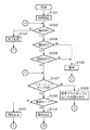
図2、図3、及び図4は本実施形態のデジタルカメラの動作を示すフローチャートであって、これらの動作は、システム制御回路40でシステムメモリ47に記憶されているプログラムを実行することにより行われる。
2, 3, and 4 are flowcharts showing operations of the digital camera according to the present embodiment. These operations are performed by executing a program stored in the
図2において、まず、ステップS101では電池交換等の電源投入により、システム制御回路40はフラグや制御変数等を初期化し、デジタルカメラ100各部において必要な所定の初期設定を行う。
In FIG. 2, first, in step S <b> 101, the system control circuit 40 initializes a flag, a control variable, and the like by turning on power such as battery replacement, and performs necessary initial settings in each part of the
次いで、ステップS102では電源スイッチ45がオンしているか否かを判断し、オンしていない場合には、ステップS103で所定の終了処理を実行し、ステップS102に戻る。すなわち、各表示部の表示を終了状態に変更し、フラグや制御変数等を含む必要なパラメータ、設定値、設定モードを不揮発性メモリ49に書き込む。さらに、電源制御部46によって画像表示部39を含む本体部102の各構成部位における不要な電源を遮断する等の終了処理を行い、ステップS102に戻る。
Next, in step S102, it is determined whether or not the
一方、ステップS102で電源スイッチ45がオンしていると判断された場合は、ステップS104に進み、電源部3を構成する電池の残容量が十分あるか否かを電源制御部46で判断する。そして、電池の残容量が十分でない場合は、表示部48で画像や音声による所定の警告表示を行った後に(ステップS105)、ステップS102に戻る。
On the other hand, if it is determined in step S102 that the
また、ステップS104で電池の残容量が十分である場合には、ステップS106に進み、第1及び/又は第2の記録部6,7が本体部102に装着されているか否かを判断する。それと同時に第1及び/又は第2の記録部6,7が本体部102に装着されている場合は、第1及び第2の記録部6,7に記録されている画像データの管理情報を取得する。そして、その動作状態が本体部102の動作、特に第1及び/又は第2の記録部6,7に対する画像データの記録再生動作に問題があるか否かを判断する。そして、問題があるならば、ステップS105に進んで表示部48から画像や音声により所定の警告表示を行った後、ステップS102に戻る。
If the remaining battery capacity is sufficient in step S104, the process proceeds to step S106, and it is determined whether the first and / or second recording units 6 and 7 are attached to the
一方、ステップS106で、記録部6,7の動作に問題がないならば、ステップS107に進み、ミラーアップモードスイッチ57がオンしているか否かを判断する。ミラーアップモードスイッチ57がONしていないならば、ステップS108に進み設定された制御モードに応じた所定の処理を実行し、実行後にステップS102の処理に戻る。
On the other hand, if there is no problem in the operation of the recording units 6 and 7 in step S106, the process proceeds to step S107 to determine whether or not the mirror up
ステップS107で、ミラーアップモードスイッチ57がオンしていると判断された場合は、ステップS109に進む。そして、ミラーアップ撮影時に、撮影の度にミラーがダウンするモードか、一度ミラーがアップした後は、ミラーダウンの指示があるまで、ミラーアップのまま撮影を行う連続モードかを判断する。そして、撮影の度にミラーがダウンするモードの場合には、ステップS111に進み、連続モードの場合には、ステップS110に進む。
If it is determined in step S107 that the mirror up
次いで、ステップS110、ステップS111では、画像や音声により本体部102の各種設定状態の表示を表示部48で行い、ステップ110の次は図3のステップS112に、ステップ111の次は図4のステップS151に進む。
Next, in step S110 and step S111, various setting states of the
なお、画像表示部39の画像表示が可能な状態に設定されている場合は画像表示部39においても画像や音声により本体部102の各種設定状態の表示を行う。
When the
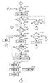
図3のステップS112では第1のシャッタースイッチ(SW1)54がオンされているか否かを判断し、第1のシャッタースイッチ54がオンされていない場合は、図2のステップS102に戻る。一方、第1のシャッタースイッチ54がオンされている場合には、ステップS113で測距・測光処理を実行してステップS114に進む。すなわち、測距処理を行って撮影レンズ17の焦点を被写体に合わせ、測光処理を行って絞り値及びシャッター時間を決定する。
In step S112 of FIG. 3, it is determined whether or not the first shutter switch (SW1) 54 is turned on. If the
次いで、ステップS114では第2のシャッタースイッチ(SW2)55がオンされたか否かを判断する。そして、第2のシャッタースイッチ55がオンされていない場合には、ステップS115に進んで第1のシャッタースイッチ(SW1)54がオンされているか否かを判断する。そして、第1のシャッタースイッチ54がオンされている場合は、ステップS114に戻る一方、第1のシャッタースイッチ(SW1)54がオン状態でなくなったときは撮影終了と判断して図2のステップS102に戻る。
Next, in step S114, it is determined whether or not the second shutter switch (SW2) 55 is turned on. If the second shutter switch 55 is not turned on, the process proceeds to step S115 to determine whether or not the first shutter switch (SW1) 54 is turned on. When the
一方、ステップS114で第2のシャッタースイッチ(SW2)55がオンされたと判断された場合は、ステップS116に進む。 On the other hand, if it is determined in step S114 that the second shutter switch (SW2) 55 is turned on, the process proceeds to step S116.
ステップS116では、クイックリターンミラー26がシステム制御回路40からの信号でミラー制御部44によってミラーアップの状態になる。 In step S116, the quick return mirror 26 enters a mirror-up state by the mirror control unit 44 in response to a signal from the system control circuit 40.
その後ステップS117で再度、第2のシャッタースイッチ(SW2)55がオンされたか否かを判断する。第2のシャッタースイッチ55がオンされていない場合は、ステップS130に進んで不図示のミラーダウンスイッチがオンしているか否かを判断する。ミラーダウンスイッチがオフの場合は、ステップS117に戻り、ミラーダウンスイッチがオンの場合は、システム制御回路40からの信号でミラー制御部44によってクイックリターンミラー26がダウンし、図2のステップS107に戻る。 Thereafter, in step S117, it is determined again whether or not the second shutter switch (SW2) 55 is turned on. If the second shutter switch 55 is not turned on, the process proceeds to step S130 to determine whether a mirror down switch (not shown) is turned on. If the mirror down switch is off, the process returns to step S117. If the mirror down switch is on, the quick return mirror 26 is lowered by the mirror control unit 44 in response to a signal from the system control circuit 40, and the process returns to step S107 in FIG. Return.
一方、ステップS117で第2のシャッタースイッチ(SW2)55がオンされたと判断したときはステップS118に進む。 On the other hand, when it is determined in step S117 that the second shutter switch (SW2) 55 is turned on, the process proceeds to step S118.
そして、ステップS118ではデータ格納が可能な記憶領域がメインメモリ34に存在するか否かを判断し、記憶領域が存在しない場合は、ステップS119で表示部48で画像や音声により所定の警告表示を行ない、その後図2のステップS102に戻る。例えば、メインメモリ34の画像記憶バッファ領域内に記憶可能な最大枚数の連写撮影を行った直後であって、メインメモリ34から第1又は第2の記録部6,7への記録書込が未だなされていない場合などでは、ステップS119に進む。 In step S118, it is determined whether or not a storage area where data can be stored exists in the main memory 34. If there is no storage area, a predetermined warning is displayed on the display unit 48 using an image or sound in step S119. Then, the process returns to step S102 in FIG. For example, immediately after performing the maximum number of continuous shots that can be stored in the image storage buffer area of the main memory 34, recording / writing from the main memory 34 to the first or second recording unit 6, 7 is performed. If it has not been done yet, the process proceeds to step S119.
なお、撮影した画像データを圧縮処理してからメインメモリ34に記憶する場合は、圧縮した後の画像データ量が圧縮モードの設定に応じて異なることを考慮し、記憶可能な領域がメインメモリ34の画像記憶バッファ領域上にあるか否かを判断する。 When the captured image data is compressed and stored in the main memory 34, the area that can be stored is the main memory 34 in consideration of the fact that the amount of image data after compression varies depending on the compression mode setting. It is determined whether or not it is in the image storage buffer area.
そして、ステップS118でメインメモリ34に記憶領域がある場合は、ステップS120で撮影処理を実行し、ステップS121に進む。すなわち、撮像して所定時間電荷蓄積された撮像信号を撮像素子30から読み出す。そして、A/D変換器31、画像処理回路36、メモリ制御回路32を介して、或いはA/D変換器31から直接メモリ制御回路32を介して、撮影した画像データをメインメモリ34の所定領域に書き込み、ステップS121に進む。
If there is a storage area in the main memory 34 in step S118, the shooting process is executed in step S120, and the process proceeds to step S121. That is, an imaging signal that has been imaged and accumulated for a predetermined time is read from the
次いで、ステップS121で撮影秒時が1秒以上の場合はステップS122に進みレンズユニット1の絞り18を絞り制御部19によってf11まで絞り込む。そして、絞り込み後にステップS123に進みダーク画像の取込み処理が行われ、その後ステップS124とステップS125に進む。
Next, when the shooting time is 1 second or longer in step S121, the process proceeds to step S122, and the
一方、ステップS121で撮影秒時が1秒より短い場合はステップS123に進んで、絞り18の絞込みを行わないで、ダーク画像の取込み処理が行われる。
On the other hand, if the shooting time is shorter than 1 second in step S121, the process proceeds to step S123, and the dark image capturing process is performed without narrowing down the
なお、ここで、ダーク画像の取り込みとは、シャッター29を閉じた状態で、撮影時と同じ時間だけ撮像素子30の電荷蓄積を行うことである。このダーク画像の取り込みにより、撮像素子で発生する暗電流などのノイズ成分のみの情報を得ることができ、例えばこのダーク画像を撮影画像から差し引くことにより、撮影画像のノイズを低減することが出来る。また、撮影秒時が例えば1秒以上の長い時間になる場合は、ダーク画像の取り込みにも同じ時間がかかることになり、シャッター29の周囲の隙間などから回折して漏れこんだ僅かな光が撮像素子に入射することが考えられる。その場合、正確なダーク画像を取り込むことが出来ない場合がある。そのため、本実施形態では、撮影秒時が長くなる場合には、ダーク画像の取り込み時に絞り18を絞り込むことにより、カメラ内に入射する光量を少しでも少なくして、正確なダーク画像を取得できるようにしている。
Here, the capturing of the dark image means that the charge of the
即ち、ダーク画像の取込み処理が行われるときに絞り18がf11まで絞り込まれ、開口面積が減少しているためにレンズユニット1からの入射光量が少なくなる。そのため、ミラーがアップしている状態でも、十分な遮光ができ、精度の良いダーク画像の取り込み処理が行われることになる。
That is, when the dark image capturing process is performed, the
なお、本実施形態では、撮影秒時が1秒以上の場合に、ダーク画像の取り込み時に絞りを絞り込むようにしたが、この時間は1秒に限定されるものではなく、ダーク画像への光の漏れこみの程度に応じて任意に設定してよいものである。 In this embodiment, when the shooting time is 1 second or more, the aperture is narrowed down when capturing the dark image. However, this time is not limited to 1 second, and the light to the dark image is not limited. It may be arbitrarily set according to the degree of leakage.
また、撮影秒時が1秒より短い場合にはレンズの絞りを絞り込むことを省略するようにしたが、ステップS123のダーク取込処理も一緒に省略してもよい。 Further, when the shooting time is shorter than 1 second, narrowing down the aperture of the lens is omitted, but the dark capturing process in step S123 may also be omitted.
さらには、絞り18を絞り込むときの絞り値をf11としたが、これに限定されるものではなく、f11よりもさらに絞り込んでも良い。
Furthermore, although the aperture value for narrowing down the
次に、ステップS124ではダーク画像の取込処理終了後にレンズユニット1の絞り18を絞り制御部19によって開放になるように制御を開始する。連続的に撮影をする場合も考慮して、このステップの動作を行うタイミングについては、次の撮影処理を開始する直前に行ってもよい。
Next, in step S124, control is started so that the
また、ステップS125ではメインメモリ34の所定領域に書き込まれた撮影画像データを読み出す。そして、システム制御回路40の内部メモリ或いはシステムメモリ47に記憶されている演算結果を用いて、AWB処理、ガンマ変換処理、色変換処理を含む各種現像処理を行う。そしてさらに、現像処理では、ステップS123のダーク画像の取込処理で取り込んだダーク画像データを用いて減算処理を行い、撮像素子30の暗電流ノイズ等を打ち消すダーク補正演算処理を行う。
In step S125, the captured image data written in a predetermined area of the main memory 34 is read out. Then, using the calculation result stored in the internal memory of the system control circuit 40 or the
次に、ステップS126ではメインメモリ34に書き込まれた画像データを読み出し、設定したモードに応じた画像圧縮処理を圧縮伸長回路35で行い、一連の処理を終えた画像データをメインメモリ34の所定領域に書き込む。
Next, in step S126, the image data written in the main memory 34 is read out, the image compression processing according to the set mode is performed by the compression /
次いで、ステップS127では記録動作を開始する。すなわち、メインメモリ34に記憶した画像データを読み出し、I/F部60,61及びコネクタ14,16を介して第1又は第2の記録部6,7に記録画像データの書込処理を開始する。なお、この記録開始処理は、撮影後の上述した一連の処理を終えた画像データの書き込みがメインメモリ34の所定領域に新たに書き込まれる毎にその記録画像データに対して実行される。また、第1又は第2の記録部6,7に画像データの書き込みを行っている間、書込動作中であることを明示するために表示部48は例えばLEDを点滅させる等の第1又は第2の記録部6,7への書込動作表示を行う。
Next, in step S127, the recording operation is started. That is, the image data stored in the main memory 34 is read out, and the writing process of the recorded image data is started in the first or second recording unit 6 or 7 via the I /
そして、ステップ124でレンズユニット1の絞り18が開放になって、更にステップ127で記録動作が終了するとステップ117に戻って上述の処理を繰り返す。
In step 124, the
図4は、図2のステップS109でミラーアップ撮影時に撮影の度にミラーがダウンするモードが選ばれた時に行われるフローチャートであり、ステップS111の続きである。 FIG. 4 is a flowchart performed when the mode in which the mirror is lowered every time shooting is selected in step S109 of FIG. 2 and is a continuation of step S111.
図4のステップS151では、第1のシャッタースイッチ(SW1)54がオンされているか否かを判断し、第1のシャッタースイッチ54がオンされていない場合には、図2のステップS102に戻る。一方、第1のシャッタースイッチ54がオンされている場合には、ステップS152で測距・測光処理を実行してステップS153に進む。すなわち、測距処理を行って撮影レンズ17の焦点を被写体に合わせ、測光処理を行って絞り値及びシャッター時間を決定する。
In step S151 in FIG. 4, it is determined whether or not the first shutter switch (SW1) 54 is turned on. If the
次いで、ステップS153では第2のシャッタースイッチ(SW2)55がオンされたか否かを判断し、オンされていない場合には、ステップS151に戻る。 Next, in step S153, it is determined whether or not the second shutter switch (SW2) 55 is turned on. If not, the process returns to step S151.
一方、ステップS153で第2のシャッタースイッチ(SW2)55がオンされたと判断したときはステップS155に進む。 On the other hand, when it is determined in step S153 that the second shutter switch (SW2) 55 is turned on, the process proceeds to step S155.
ステップS155では、クイックリターンミラー26がシステム制御回路40からの信号でミラー制御部44によってミラーアップの状態になる。 In step S155, the quick return mirror 26 enters a mirror-up state by the mirror control unit 44 in response to a signal from the system control circuit 40.
その後、ステップS156で再度、第2のシャッタースイッチ(SW2)55がオンされたか否かを判断し、オンされていない場合は、ステップS157に進んでミラーアップモードスイッチ57がオンしているか否かを判断する。ミラーアップモードスイッチ57がオンされていない場合は、ステップS158に進んで、システム制御回路40からの信号でミラー制御部44によってクイックリターンミラー26がダウンして、その後図2のステップ102に戻る。
Thereafter, in step S156, it is determined again whether or not the second shutter switch (SW2) 55 is turned on. If not, the process proceeds to step S157, and whether or not the mirror up
ステップS157でミラーアップモードスイッチ57がオンのときはステップ156に戻る。
If the mirror up
一方、ステップS156で第2のシャッタースイッチ(SW2)55がオンされたと判断したときはステップS159に進む。 On the other hand, when it is determined in step S156 that the second shutter switch (SW2) 55 is turned on, the process proceeds to step S159.
そして、ステップS159ではデータ格納が可能な記憶領域がメインメモリ34に存在するか否かを判断し、記憶領域が存在しない場合は、ステップS160で表示部48で画像や音声により所定の警告表示を行ない、その後図2のステップS102に戻る。例えば、メインメモリ34の画像記憶バッファ領域内に記憶可能な最大枚数の連写撮影を行った直後であって、メインメモリ34から第1又は第2の記録部6,7への記録書込が未だなされていない場合などは、ステップS160に進む。 In step S159, it is determined whether or not a storage area in which data can be stored exists in the main memory 34. If no storage area exists, a predetermined warning is displayed on the display unit 48 using an image or sound in step S160. Then, the process returns to step S102 in FIG. For example, immediately after performing the maximum number of continuous shots that can be stored in the image storage buffer area of the main memory 34, recording / writing from the main memory 34 to the first or second recording unit 6, 7 is performed. If it has not been done yet, the process proceeds to step S160.
なお、撮影した画像データを圧縮処理してからメインメモリ34に記憶する場合は、圧縮した後の画像データ量が圧縮モードの設定に応じて異なることを考慮し、記憶可能な領域がメインメモリ34の画像記憶バッファ領域上にあるか否かを判断する。 When the captured image data is compressed and stored in the main memory 34, the area that can be stored is the main memory 34 in consideration of the fact that the amount of image data after compression varies depending on the compression mode setting. It is determined whether or not it is in the image storage buffer area.
そして、ステップS159でメインメモリ34に記憶領域が存在する場合は、ステップS161で撮影処理を実行し、ステップS162に進む。すなわち、撮像して所定時間電荷蓄積された撮像信号を撮像素子30から読み出す。そして、A/D変換器31、画像処理回路36、メモリ制御回路32を介して、或いはA/D変換器31から直接メモリ制御回路32を介して、撮影した画像データをメインメモリ34の所定領域に書き込み、ステップS162に進む。
If there is a storage area in the main memory 34 in step S159, the shooting process is executed in step S161, and the process proceeds to step S162. That is, an imaging signal that has been imaged and accumulated for a predetermined time is read from the
次いで、ステップS162では撮影処理終了後に、クイックリターンミラー26がシステム制御回路40からの信号でミラー制御部44によってミラーダウンの状態になる。その後ステップS163に進んでダーク画像の取込処理が行われる。 Next, in step S162, after the photographing process is completed, the quick return mirror 26 is brought into a mirror-down state by the mirror control unit 44 in response to a signal from the system control circuit 40. Thereafter, the process proceeds to step S163, where dark image capturing processing is performed.
ステップS164ではメインメモリ34の所定領域に書き込まれた撮影画像データを読み出す。そして、システム制御回路40の内部メモリ或いはシステムメモリ47に記憶されている演算結果を用いて、AWB処理、ガンマ変換処理、色変換処理を含む各種現像処理を行う。そしてさらに、この現像処理では、ステップS163のダーク画像の取込処理で取り込んだダーク画像データを用いて減算処理を行い、撮像素子30の暗電流ノイズ等を打ち消すダーク補正演算処理を行う。
In step S164, the captured image data written in the predetermined area of the main memory 34 is read out. Then, using the calculation result stored in the internal memory of the system control circuit 40 or the
次に、ステップS165ではメインメモリ34に書き込まれた画像データを読み出し、設定したモードに応じた画像圧縮処理を圧縮伸長回路35で行い、一連の処理を終えた画像データをメインメモリ34の所定領域に書き込む。
Next, in step S165, the image data written in the main memory 34 is read out, the image compression processing corresponding to the set mode is performed by the compression /
次いで、ステップS166では記録動作を開始する。すなわち、メインメモリ34に記憶した画像データを読み出し、I/F部60,61及びコネクタ14,16を介して第1又は第2の記録部6,7に記録画像データの書込処理を開始する。なお、この記録開始処理は、撮影後の上述した一連の処理を終えた画像データの書き込みがメインメモリ34の所定領域に新たに書き込まれる毎にその記録画像データに対して実行される。また、第1又は第2の記録部6,7に画像データの書き込みを行っている間、書込動作中であることを明示するために表示部48は例えばLEDを点滅させる等の第1又は第2の記録部6,7への書込動作表示を行う。
Next, in step S166, the recording operation is started. That is, the image data stored in the main memory 34 is read out, and the writing process of the recorded image data is started in the first or second recording unit 6 or 7 via the I /
その後ステップ151に戻って上述の処理を繰り返す。 Thereafter, the process returns to step 151 and the above-described processing is repeated.
図5は、図3のステップS113で実行される測距・測光処理ルーチンのフローチャートで、図4のステップS152も同じ処理である。 FIG. 5 is a flowchart of the distance measurement / photometry processing routine executed in step S113 of FIG. 3, and step S152 of FIG. 4 is the same process.
なお、測距・測光処理では、システム制御回路40と絞り制御部19又は測距制御部20との間の各種信号の授受は、I/F部59、コネクタ11、コネクタ10、I/F部23、レンズシステム制御回路22を介して行われる。
In the distance measurement / photometry process, the transmission / reception of various signals between the system control circuit 40 and the
まず、ステップS201では、測距部41及び測距制御部20を使用してAF処理を開始する。次いでステップS202では光学像として結像された画像の合焦状態を判断し、測距制御部20により撮像レンズ17を駆動させ、且つ測距部41で合焦状態を検出する。そして、続くステップS203で測距が適正か否かを判断し、適正でない場合は、ステップS202に戻って測距制御を続行する。一方、測距が適正である場合は、ステップS204に進み、撮影画面内の複数の測距点の中から合焦した測距点を決定し、決定した測距点データと共に測距データをシステム制御回路40の内部メモリ或いはシステムメモリ47に記憶しステップS205に進む。
First, in step S201, the AF process is started using the distance measurement unit 41 and the distance
ステップS205では測光部42を使用してAE処理を開始する。すなわち、撮像レンズ17に入射した光学像を測光部42に供給し、光学像として結像された画像の露出状態を測定する。次いでステップS207では露出状態が適正か否かを判断し、適正でない場合は、ステップS206に戻って測光制御を続行する。一方、露出状態が適正である場合は、測光データをシステム制御回路40の内部メモリ又はシステムメモリ47に記憶した後にメインルーチン(図3及び図4)に戻る。なお、測光処理で検出した露出結果とモードダイヤル53で設定した制御モードとに応じて絞り値、シャッター速度が決定され、そのシャッター速度に応じて撮像素子30の電荷蓄積時間が決定される。そして、その電荷蓄積時間に基づいて撮影処理やダーク画像の取込処理を行う。
In step S205, the
図6は、図3及び図4で実行される撮影処理ルーチンのフローチャートである。 FIG. 6 is a flowchart of the photographing process routine executed in FIGS. 3 and 4.
なお、撮影処理では、システム制御回路40と絞り制御部19又は測距制御部20との間の各種信号の授受は、I/F部59、コネクタ11、コネクタ10、I/F部23及びレンズシステム制御回路22を介して行われる。
In the photographing process, transmission / reception of various signals between the system control circuit 40 and the
ステップS301で撮像素子30の蓄積電荷をクリアした後、ステップS302で撮像素子30への電荷蓄積を開始する。次いで、ステップS304でシャッター制御部43を駆動させてシャッター29を開状態とし、ステップS305で撮像素子30への露光を行う。
After clearing the accumulated charge in the
また、ステップS303では所定の絞り値までレンズユニット1の絞り18を絞り制御部19によって絞り込む。
In step S303, the
次に、ステップS306では所定の露光時間に合わせてシャッター制御部43によってシャッター29を閉状態とし撮像素子30の露光を終了する。
Next, in step S306, the
次に、ステップS307では設定した電荷蓄積時間が経過したか否かを判断し、ステップ308では設定した電荷蓄積時間が経過したときは撮像素子30の電荷蓄積を終了する。次いで、ステップ309では撮像素子30から蓄積された画像信号を読み出す。そして、A/D変換器31、画像処理回路36、メモリ制御回路32を介し、或いはA/D変換器31から直接メモリ制御回路32を介してメインメモリ34に撮影画像データの書き込みを行い、メインルーチン(図3及び図4)に戻る。
Next, in step S307, it is determined whether or not the set charge accumulation time has elapsed. In
ステップS310ではレンズユニット1の絞り18を開放に戻す。
In step S310, the
図7は、図3及び図4で実行されるダーク画像の取込処理ルーチンのフローチャートである。 FIG. 7 is a flowchart of the dark image capturing process routine executed in FIGS. 3 and 4.
ステップS401で撮像素子30の蓄積電荷をクリアし、ステップS402でシャッター29を閉状態にしたままで撮像素子30の電荷蓄積を開始する。そして、ステップS403では、設定した所定の電荷蓄積時間が経過したか否かを判断し、所定の電荷蓄積時間が経過した場合に、ステップS404に進んで撮像素子30の電荷蓄積を終了する。通常は、撮影処理を行った時の時間と同じ時間の電荷蓄積を行う。その後、ステップS405で撮像素子30からダーク画像データを読み出す。そして、A/D変換器31、画像処理回路36、メモリ制御回路32を介して、或いはA/D換器31から直接メモリ制御回路32を介して、メインメモリ34にダーク画像データを書き込んでメインルーチン(図3及び図4)に戻る。
In step S401, the accumulated charge of the
そして、このダークノイズ補正データ(ダーク画像データ)を使用して現像処理を行うことで、撮像素子30の発生する暗電流ノイズや撮像素子30に生じた微小な傷に起因する画素欠損等の画質劣化に関して、撮影した画像データを補正することができる。
Then, by performing development processing using this dark noise correction data (dark image data), image quality such as dark current noise generated by the
なお、本発明は上記の実施形態に限定されるものではない。上記の実施形態では撮影処理の電荷蓄積時間とダーク画像の取り込み処理の電荷蓄積時間を同一としているが、暗電流ノイズ等を補正するのに十分なデータが得られる範囲内であれば、異なる電荷蓄積時間にしてもよい。 In addition, this invention is not limited to said embodiment. In the above embodiment, the charge accumulation time for the photographing process and the charge accumulation time for the dark image capturing process are the same. However, different charges may be used as long as sufficient data can be obtained to correct dark current noise and the like. The accumulation time may be set.
また、撮影時間が1秒以上の場合に、レンズの絞りをf11まで絞るようにしたが、撮影時間及びレンズの絞り値に関してもこれに限定されるものではない。 Further, when the shooting time is 1 second or longer, the lens aperture is set to f11. However, the shooting time and the lens aperture value are not limited thereto.
また、ダーク画像の取込処理(ステップS123又はステップS163)の動作中は、撮影動作を行うことができない。そのため、これを外部に報知させるべく、表示部48又は画像表示部39により本体部102がビジー状態であることを示す画像や音声の表示を行うようにしてもよい。
Further, during the operation of the dark image capturing process (step S123 or step S163), the photographing operation cannot be performed. For this reason, an image or sound indicating that the
また、第1及び第2の記録部6,7に装着される記録媒体についても、PCカードやコンパクトフラッシュ(登録商標)等のメモリカード、ハ―ドディスクに限られない。例えば、マイクロDATや光磁気ディスク、CD−RやCD−WR等の光ディスク、DVD等の相変化型光ディスク等で構成してもよいことはいうまでもない。また、第1及び第2の記録部6,7に関して、例えば、メモリカードとハードディスク等が一体となった複合記録媒体が装着可能となるようにしてもよく、この複合記録媒体の一部を着脱自在に構成してもよい。 Further, the recording medium loaded in the first and second recording units 6 and 7 is not limited to a memory card such as a PC card or a compact flash (registered trademark) or a hard disk. For example, it goes without saying that it may be constituted by a micro DAT, a magneto-optical disk, an optical disk such as a CD-R or CD-WR, a phase change optical disk such as a DVD, or the like. For the first and second recording units 6 and 7, for example, a composite recording medium in which a memory card and a hard disk are integrated may be attachable. A part of the composite recording medium may be attached or detached. You may comprise freely.
また、上記の実施形態では第1及び第2の記録部6,7は本体部102に着脱自在に装着されているが、少なくとも一方を本体部102に一体的に固着するようにしてもよい。
In the above embodiment, the first and second recording units 6 and 7 are detachably attached to the
また、上記の実施形態では、画像処理回路36で必要に応じて、撮像した画像データを用いて所定の演算処理を行っている。そして、得られた演算結果に基づいてシステム制御回路40がシャッター制御部43、測距部41等に対して制御を行うTTL方式のAF処理、AE処理、EF処理等を行っている。しかし、測距部41及び測光部42のみでAF処理、AE処理、EF処理の各処理を行い、画像処理回路36ではAF処理、AE処理、EF処理の各処理を行わない構成としても良い。
In the above embodiment, the
また、測距部41による測定結果と撮像素子30によって撮像した撮像画像データと画像処理回路36で演算した演算結果とに基づいてAF制御を行ってもよい。また、測光部42による測定結果と、撮像素子30によって撮像した撮像画像データと画像処理回路36によって演算した演算結果とに基づいてAE制御を行っても構わない。
Further, the AF control may be performed based on the measurement result by the distance measuring unit 41, the captured image data captured by the
なお、撮像素子30によって撮像された画像データを画像処理回路36によって演算し、画像処理回路36での演算結果に基づき、システム制御回路40がシャター制御部43、絞り制御部19、測距制御部20に対して制御を行うようにしても良い。即ち、このビデオTTL方式を使用し、AE制御やAF制御をすることも可能である。
The image data picked up by the
(他の実施形態)
また、各実施形態の目的は、次のような方法によっても達成される。すなわち、前述した実施形態の機能を実現するソフトウェアのプログラムコードを記録した記憶媒体(または記録媒体)を、システムあるいは装置に供給する。そして、そのシステムあるいは装置のコンピュータ(またはCPUやMPU)が記憶媒体に格納されたプログラムコードを読み出し実行する。この場合、記憶媒体から読み出されたプログラムコード自体が前述した実施形態の機能を実現することになり、そのプログラムコードを記憶した記憶媒体は本発明を構成することになる。また、コンピュータが読み出したプログラムコードを実行することにより、前述した実施形態の機能が実現されるだけでなく、本発明には次のような場合も含まれる。すなわち、プログラムコードの指示に基づき、コンピュータ上で稼働しているオペレーティングシステム(OS)などが実際の処理の一部または全部を行い、その処理によって前述した実施形態の機能が実現される。
(Other embodiments)
The object of each embodiment is also achieved by the following method. That is, a storage medium (or recording medium) in which a program code of software that realizes the functions of the above-described embodiments is recorded is supplied to the system or apparatus. Then, the computer (or CPU or MPU) of the system or apparatus reads and executes the program code stored in the storage medium. In this case, the program code itself read from the storage medium realizes the functions of the above-described embodiments, and the storage medium storing the program code constitutes the present invention. Further, by executing the program code read by the computer, not only the functions of the above-described embodiments are realized, but the present invention includes the following cases. That is, based on the instruction of the program code, an operating system (OS) running on the computer performs part or all of the actual processing, and the functions of the above-described embodiments are realized by the processing.
さらに、次のような場合も本発明に含まれる。すなわち、記憶媒体から読み出されたプログラムコードが、コンピュータに挿入された機能拡張カードやコンピュータに接続された機能拡張ユニットに備わるメモリに書き込まれる。その後、そのプログラムコードの指示に基づき、その機能拡張カードや機能拡張ユニットに備わるCPUなどが実際の処理の一部または全部を行い、その処理によって前述した実施形態の機能が実現される。 Furthermore, the following cases are also included in the present invention. That is, the program code read from the storage medium is written in a memory provided in a function expansion card inserted into the computer or a function expansion unit connected to the computer. Thereafter, based on the instruction of the program code, the CPU or the like provided in the function expansion card or function expansion unit performs part or all of the actual processing, and the functions of the above-described embodiments are realized by the processing.
本発明を上記記憶媒体に適用する場合、その記憶媒体には、先に説明した手順に対応するプログラムコードが格納されることになる。 When the present invention is applied to the above storage medium, the storage medium stores program codes corresponding to the procedure described above.
17 撮像レンズ
18 絞り
19 絞り制御回路
26 クイックリターンミラー
29 シャッター
30 撮像素子
32 メモリ制御回路
36 画像処理回路
44 ミラー制御部
DESCRIPTION OF SYMBOLS 17
Claims (5)
前記撮影レンズと前記撮像素子の間に設けられ、開くことにより前記撮像素子を露光させ、閉じることにより前記撮像素子を遮光するシャッターと、
前記撮影レンズから前記撮像素子に至る光路上に設けられ、該光路上の位置と、該光路上から逃げた位置とに移動が可能なクイックリターンミラーと、
前記シャッターを閉じて前記撮像素子に電荷蓄積を行なわせ、前記撮像素子を露光しない状態での画像であるダーク画像を取得する取得手段と、
前記クイックリターンミラーを前記光路上から逃がした状態で前記ダーク画像を取得する場合に、前記撮影レンズに備えられた絞りを、予め定められた開口面積よりも小さい開口面積になるように制御する制御手段と、
を具備することを特徴とする撮像装置。 An image sensor that converts an object image formed by the taking lens into an electrical signal ;
A shutter that is provided between the photographing lens and the image sensor, exposes the image sensor by opening, and shields the image sensor by closing;
A quick return mirror that is provided on an optical path from the photographing lens to the image sensor and is movable to a position on the optical path and a position that escapes from the optical path;
Close the shutter to perform the charge accumulated in the imaging element, and the obtained means preparative for acquiring the dark image is an image in a state where no exposure of the imaging element,
Control for controlling a diaphragm provided in the photographing lens so that the aperture area is smaller than a predetermined aperture area when the dark image is acquired in a state where the quick return mirror is escaped from the optical path. Means,
An imaging apparatus comprising:
前記シャッターを閉じて前記撮像素子に電荷蓄積を行なわせ、前記撮像素子を露光しない状態での画像であるダーク画像を取得する取得工程と、
前記クイックリターンミラーを前記光路上から逃がした状態で前記ダーク画像を取得する場合に、前記撮影レンズに備えられた絞りを、予め定められた開口面積よりも小さい開口面積になるように制御する制御工程と、
を具備することを特徴とする撮像装置の制御方法。 An image sensor that converts an object image formed by the photographic lens into an electrical signal, and provided between the photographic lens and the image sensor. The image sensor is exposed by opening, and the image sensor is shielded by closing. And an image pickup apparatus provided on an optical path from the photographing lens to the image sensor and capable of moving to a position on the optical path and a position escaped from the optical path. A way to
Close the shutter to perform the charge accumulated in the imaging element, and the resulting steps taken to obtain the dark image is an image in a state where no exposure of the imaging element,
Control for controlling a diaphragm provided in the photographing lens so that the aperture area is smaller than a predetermined aperture area when the dark image is acquired in a state where the quick return mirror is escaped from the optical path. Process,
An image pickup apparatus control method comprising:
Priority Applications (3)
| Application Number | Priority Date | Filing Date | Title |
|---|---|---|---|
| JP2007006417A JP4761570B2 (en) | 2007-01-15 | 2007-01-15 | IMAGING DEVICE, ITS CONTROL METHOD, PROGRAM, AND STORAGE MEDIUM |
| US11/972,438 US7760999B2 (en) | 2007-01-15 | 2008-01-10 | Image capturing apparatus, control method thereof, program, and storage medium |
| EP08100456A EP1944964A3 (en) | 2007-01-15 | 2008-01-14 | Image capturing apparatus, control method thereof, program and storage medium |
Applications Claiming Priority (1)
| Application Number | Priority Date | Filing Date | Title |
|---|---|---|---|
| JP2007006417A JP4761570B2 (en) | 2007-01-15 | 2007-01-15 | IMAGING DEVICE, ITS CONTROL METHOD, PROGRAM, AND STORAGE MEDIUM |
Publications (3)
| Publication Number | Publication Date |
|---|---|
| JP2008172731A JP2008172731A (en) | 2008-07-24 |
| JP2008172731A5 JP2008172731A5 (en) | 2010-02-12 |
| JP4761570B2 true JP4761570B2 (en) | 2011-08-31 |
Family
ID=39464729
Family Applications (1)
| Application Number | Title | Priority Date | Filing Date |
|---|---|---|---|
| JP2007006417A Expired - Fee Related JP4761570B2 (en) | 2007-01-15 | 2007-01-15 | IMAGING DEVICE, ITS CONTROL METHOD, PROGRAM, AND STORAGE MEDIUM |
Country Status (3)
| Country | Link |
|---|---|
| US (1) | US7760999B2 (en) |
| EP (1) | EP1944964A3 (en) |
| JP (1) | JP4761570B2 (en) |
Families Citing this family (5)
| Publication number | Priority date | Publication date | Assignee | Title |
|---|---|---|---|---|
| JP5519976B2 (en) * | 2009-08-27 | 2014-06-11 | キヤノン株式会社 | Imaging device |
| JP5550304B2 (en) * | 2009-10-19 | 2014-07-16 | キヤノン株式会社 | Imaging device |
| JP2012156679A (en) * | 2011-01-25 | 2012-08-16 | Ricoh Co Ltd | Imaging apparatus, imaging method, and imaging program |
| JP5957925B2 (en) | 2012-02-08 | 2016-07-27 | リコーイメージング株式会社 | Dark exposure control device |
| US8964092B2 (en) * | 2012-12-26 | 2015-02-24 | Sandisk Technologies Inc. | Storage device, digital camera device, and method for displaying an alert image |
Family Cites Families (5)
| Publication number | Priority date | Publication date | Assignee | Title |
|---|---|---|---|---|
| JP3610115B2 (en) * | 1994-05-20 | 2005-01-12 | キヤノン株式会社 | Imaging device |
| JP3814346B2 (en) * | 1996-09-26 | 2006-08-30 | マミヤ・オーピー株式会社 | Aperture control device for single-lens reflex camera |
| US7292274B2 (en) * | 2001-11-06 | 2007-11-06 | Eastman Kodak Company | Solid-state image pickup device driving method and image capturing apparatus for outputting high-resolution signals for still images and moving images of improved quality at a high frame rate |
| JP3605084B2 (en) | 2002-03-08 | 2004-12-22 | キヤノン株式会社 | Image data correction device, image processing device, image data correction method, program, and storage medium |
| US7317481B2 (en) * | 2002-02-20 | 2008-01-08 | Canon Kabushiki Kaisha | Image data correction processing based on sensitivity |
-
2007
- 2007-01-15 JP JP2007006417A patent/JP4761570B2/en not_active Expired - Fee Related
-
2008
- 2008-01-10 US US11/972,438 patent/US7760999B2/en not_active Expired - Fee Related
- 2008-01-14 EP EP08100456A patent/EP1944964A3/en not_active Ceased
Also Published As
| Publication number | Publication date |
|---|---|
| US20080170850A1 (en) | 2008-07-17 |
| US7760999B2 (en) | 2010-07-20 |
| EP1944964A2 (en) | 2008-07-16 |
| JP2008172731A (en) | 2008-07-24 |
| EP1944964A3 (en) | 2011-12-07 |
Similar Documents
| Publication | Publication Date | Title |
|---|---|---|
| JP4378341B2 (en) | Imaging apparatus and correction method | |
| JP4989385B2 (en) | Imaging apparatus, control method thereof, and program | |
| JP4794978B2 (en) | Image processing apparatus, control method, and program | |
| JP2009033267A (en) | Image capturing apparatus, control method thereof, and program | |
| JP4532819B2 (en) | Imaging device | |
| JP4761570B2 (en) | IMAGING DEVICE, ITS CONTROL METHOD, PROGRAM, AND STORAGE MEDIUM | |
| JP2005045552A (en) | Imaging device and its method | |
| JP3605084B2 (en) | Image data correction device, image processing device, image data correction method, program, and storage medium | |
| JP2005311600A (en) | Image pick-up device and method | |
| JP2007228055A (en) | Electronic camera | |
| JP2003333434A (en) | Device and method for picking-up image, program, and recording medium | |
| JP2005292740A (en) | Electronic camera | |
| JP4393177B2 (en) | Imaging apparatus and imaging method | |
| JP4411053B2 (en) | IMAGING DEVICE, ITS CONTROL METHOD, CONTROL PROGRAM, AND STORAGE MEDIUM | |
| JP3703436B2 (en) | Image processing apparatus, image processing method, and program | |
| JP2000201294A (en) | Image pickup device, image processor, image processing method and storage medium | |
| JP2006109162A (en) | Imaging apparatus, imaging method, program, and storage medium | |
| JP2005051697A (en) | Imaging apparatus | |
| JP2001320634A (en) | Image pickup device, its control method and computer- readable medium | |
| JP4682104B2 (en) | Imaging device | |
| JP4926609B2 (en) | Imaging device | |
| JP2000184269A (en) | Image pickup device, control method for the image pickup device and recoding medium | |
| JP2002135636A (en) | Electronic camera | |
| JP2005057691A (en) | Imaging apparatus and method | |
| JP3359314B2 (en) | Imaging device, image processing device, image processing method, and storage medium |
Legal Events
| Date | Code | Title | Description |
|---|---|---|---|
| A521 | Request for written amendment filed |
Free format text: JAPANESE INTERMEDIATE CODE: A523 Effective date: 20091216 |
|
| A621 | Written request for application examination |
Free format text: JAPANESE INTERMEDIATE CODE: A621 Effective date: 20091216 |
|
| A977 | Report on retrieval |
Free format text: JAPANESE INTERMEDIATE CODE: A971007 Effective date: 20110527 |
|
| TRDD | Decision of grant or rejection written | ||
| A01 | Written decision to grant a patent or to grant a registration (utility model) |
Free format text: JAPANESE INTERMEDIATE CODE: A01 Effective date: 20110603 |
|
| A01 | Written decision to grant a patent or to grant a registration (utility model) |
Free format text: JAPANESE INTERMEDIATE CODE: A01 |
|
| A61 | First payment of annual fees (during grant procedure) |
Free format text: JAPANESE INTERMEDIATE CODE: A61 Effective date: 20110606 |
|
| FPAY | Renewal fee payment (event date is renewal date of database) |
Free format text: PAYMENT UNTIL: 20140617 Year of fee payment: 3 |
|
| R150 | Certificate of patent or registration of utility model |
Ref document number: 4761570 Country of ref document: JP Free format text: JAPANESE INTERMEDIATE CODE: R150 Free format text: JAPANESE INTERMEDIATE CODE: R150 |
|
| LAPS | Cancellation because of no payment of annual fees |