JP4759148B2 - Apparatus and method for increasing x-ray tube power per target thermal load - Google Patents
Apparatus and method for increasing x-ray tube power per target thermal load Download PDFInfo
- Publication number
- JP4759148B2 JP4759148B2 JP2001015167A JP2001015167A JP4759148B2 JP 4759148 B2 JP4759148 B2 JP 4759148B2 JP 2001015167 A JP2001015167 A JP 2001015167A JP 2001015167 A JP2001015167 A JP 2001015167A JP 4759148 B2 JP4759148 B2 JP 4759148B2
- Authority
- JP
- Japan
- Prior art keywords
- target
- angle
- electron beam
- ray tube
- ray
- Prior art date
- Legal status (The legal status is an assumption and is not a legal conclusion. Google has not performed a legal analysis and makes no representation as to the accuracy of the status listed.)
- Expired - Fee Related
Links
Images


Classifications
-
- H—ELECTRICITY
- H01—ELECTRIC ELEMENTS
- H01J—ELECTRIC DISCHARGE TUBES OR DISCHARGE LAMPS
- H01J35/00—X-ray tubes
-
- H—ELECTRICITY
- H01—ELECTRIC ELEMENTS
- H01J—ELECTRIC DISCHARGE TUBES OR DISCHARGE LAMPS
- H01J35/00—X-ray tubes
- H01J35/02—Details
- H01J35/14—Arrangements for concentrating, focusing, or directing the cathode ray
- H01J35/147—Spot size control
Description
【0001】
【発明の属する技術分野】
本発明は一般的にはX線管に関し、特に、ターゲットに加えられたパワーに対するX線エネルギー束の比がより大きいX線管に関する。
【0002】
【従来の技術】
医療分野で使用されるX線装置は、通常、加熱されて電子のビームを放出する陰極と、一方の表面が陰極に対向するターゲットを有する(通常、回転する)陽極と、窓取付け部により固定されたX線透過窓を含むガラス及び/又は金属製の周囲フレームとを含むX線管を含む。通常、陰極は、電子がターゲット表面上の焦点にターゲット表面に対してほぼ90°の角度で入射するように方向づけられる。放出された電子の一部は、ターゲット表面に入射してX線を発生し、そのX線の一部は、X線ビームとしてX線透過窓を介してフレームから出射する。通常、X線窓は、ターゲット表面に対してほぼ7°の角度でターゲット表面から離間するX線を受けられるように配置される。放出された電子の中には、ターゲット表面に入射した時に、X線を発生せずに後方散乱するものもある。後方散乱した電子の多くは、続けて、X線透過窓及び窓取付け部を含むフレームに入射し、フレームを加熱する。フレームは、熱放射線などのその他の熱源により内側からも加熱される。加熱されたフレームは、通常、フレームと専用のX線透過窓を有する周囲ケーシングとの間に位置する油又は水などの液体冷媒により冷却される。
【0003】
【発明が解決しようとする課題】
ターゲット表面に入射する電子のパワーのほぼ1パーセント未満は、X線のパワーに変換される。電子ビームのパワーを増加すれば、管のX線パワー出力も増加するであろう。しかしながら、電子ビームのパワーを増加すると、ターゲットの熱負荷が許容し難いほど高くなり、最終的に、X線パワー出力が制限されることになる。ターゲットの熱負荷当りのX線管パワーの比を増加させるためのX線管構体及びX線を発生する方法が必要とされている。
【0004】
【課題を解決するための手段】
本発明の第1の実施態様において、X線管構体は、X線管陽極、X線管陰極及びX線管窓を含む。陽極は、表面を有するX線発生ターゲットを含む。陰極は電子ビーム軸を有する。電子ビーム軸は焦点においてターゲット表面と交差し、かつターゲットの表面に対して第1の角度で方向づけられる。第1の角度は15°〜60°の範囲にある。窓は中心点を有する表面を含み、焦点と中心点とを結ぶ線はターゲット表面に対して第2の角度をなす。
【0005】
本発明の第2の実施態様において、X線管構体は、X線管陽極、X線管陰極及びX線管窓を含む。陽極は表面を有するX線発生ターゲットを含む。陰極は電子ビーム軸を有する。電子ビーム軸は焦点においてターゲット表面と交差し、かつターゲットの表面に対して第1の角度で方向づけられる。第1の角度は15°〜60°の範囲にある。X線管陰極は、ターゲットに入射したときにほぼ200kV未満のエネルギーを有するX線を生じさせる電子を発生する。窓は中心点を有する表面を含み、焦点と中心点とを結ぶ線は、ターゲット表面に対して第2の角度をなす。第2の角度は第1の角度より小さい。電子ビーム軸及び中心点は、ターゲット表面に対してほぼ垂直に方向づけられる平面を規定する。
【0006】
本発明の第1の方法は、X線を発生するための方法であり、過程a)からc)を含む。過程a)は、電子ビーム軸を有する電子ビームを発生することを含む。過程b)は、電子ビーム軸がX線ターゲットの表面に対して15°〜60°の範囲の第1の角度をなすように、電子ビームを方向づけてX線発生ターゲットの表面上の焦点に入射させて、X線を発生することを含む。過程c)は、ターゲットの表面に対して第2の角度をなすこれらのX線を利用することを含む。
【0007】
本発明の第2の方法は、X線を発生するための方法であり、過程a)からc)を含む。過程a)は、電子ビーム軸を有する電子ビームを発生することを含む。過程b)は、電子ビーム軸がX線ターゲットの表面に対して15°〜60°の範囲の第1の角度をなすように、電子ビームを方向づけてX線発生ターゲットの表面上の焦点に入射させて、ほぼ200kV未満のエネルギーを有するX線を発生することを含む。過程c)は、ターゲットの表面に対して第1の角度よりも小さい第2の角度をなし、かつ電子ビーム軸とともに、ターゲットの表面に対してほぼ垂直に方向づけられる平面を規定するX線を利用することを含む。
【0008】
本発明に従って、第1の角度(通常、電子ビーム入射角と呼ばれるが、ここでは「α」とする)及び第2の角度(通常、X線放出角と呼ばれるが、ここでは「β」とする)を選択することにより、幾つかの利益及び利点が得られる。例えば、実験データを用いて行われたコンピュータによるベンチマークシミュレーションは、βが7°に等しく、αが15°〜20°に等しい場合、ほぼ1.5のX線エネルギー束の増加を示している。この増加は、βが7°でαが9°である従来技術の構成によるX線エネルギー束と比較して計算される。その比較において、ターゲットに加えられたパワー(すなわち、温度により測定された熱負荷)及びターゲットの焦点温度は、本発明の構成及び従来技術の構成の両方において同一であり、本発明の構成のX線スペクトルが、適正に比較を行なうために、従来技術の構成と同じ平均フォトン(すなわち、X線)エネルギーを得るべくろ過されることは、当業者には明らかなことであろう。1.5の増加は、本発明の構成のターゲットにおける同じ熱負荷及び同じ焦点温度に対するX線パワー出力が、従来技術の構成と比較して50パーセント増加したことを意味する。また、本発明の構成のX線管は、従来技術の構成のX線管と比較して、同じX線パワー出力且つより低い温度で(管の寿命を延ばすために)動作させることができる。
【0009】
【発明の実施の形態】
次に、図面において、図1は、本発明のX線管構体10の一実施例を概略的に示す。図1に示す第1の実施態様において、X線管構体10は、X線管陽極12、X線管陰極14及びX線管窓16を含む。陽極12は、表面20を有するX線発生ターゲット18を含む。陰極14は、電子ビーム軸22を含む。電子ビーム軸22は、焦点24でターゲット18の表面20と交差し、ターゲット18の表面20に対して第1の角度26で方向づけられる。第1の角度26は、15°〜60°の範囲にある。窓16は、当業者には知られるように、X線透過窓であり、中心点30を有する表面28を含む。中心点30は、幾何学的な中心点である。例えば、窓の表面が矩形の形状である場合、中心点は、その矩形の対角線の交差する点である。焦点24と中心点30とを結ぶ線32は、ターゲット18の表面20に対して第2の角度34をなす。
【0010】
一設計例において、第1の角度26は15°〜30°の範囲にあり、第2の角度34は5°〜15°の範囲にある。別の設計例において、第1の角度26はほぼ20°であり、第2の角度34はほぼ7°である。本発明を説明するにあたり、用語「ほぼx°」は、「x°±2°」を意味する。一構成において、電子ビーム軸22及び中心点30は、通常、ターゲット18の表面20に対してほぼ垂直に方向づけられる平面(すなわち、図1の紙面)を規定する。本発明を説明するにあたり、用語「ほぼ垂直」は、「垂直±2°」を意味する。一例において、陰極14は、ほぼ200kV未満のエネルギーを有するX線を発生するターゲット18に入射する電子(電子ビーム軸22を中心として一列になるように配置される)を発生する。線32を中心として一列になるように配置されるX線の中には、窓16を通過し、医療的な診察などの種々の目的に使用されるものもある。通常、医療的な診察に使用されるX線は、ほぼ200kV未満のエネルギーを有する。本発明を説明するにあたり、用語「ほぼ200kV未満」は、「205kV未満」を意味する。なお、電子ビーム軸22は、軌道が電子ビーム軸22と一致するこれらの電子の進行方向を示す指向性の線である。また、線32は、軌道が線32と一致するX線の進行方向を示す指向性のある線である。一実施例において、第2の角度34は、第1の角度26より小さい。
【0011】
図1に示す第2の実施態様において、X線管構体10は、X線管陽極12、X線管陰極14及びX線管窓16を含む。陽極12は、表面20を有するX線発生ターゲット18を含む。陰極14は、電子ビーム軸22を含む。電子ビーム軸22は、焦点24でターゲット18の表面20と交差し、かつターゲット18の表面20に対して第1の角度26で方向づけられる。第1の角度26は、15°〜60°の範囲にある。陰極14は、ターゲット18に入射したときにほぼ200kV未満のエネルギーを有するX線を生じさせる電子を発生する。窓16は、当業者には知られるように、X線透過窓であり、中心点30を有する表面28を含む。中心点30は、幾何学的な中心点である。焦点24と中心点30とを結ぶ線32は、ターゲット18の表面20に対して第2の角度34をなす。第2の角度34は、第1の角度26より小さい。電子ビーム軸22及び中心点30は、ターゲット18の表面20に対してほぼ垂直に方向づけられる平面(すなわち、図1の紙面)を規定する。一設計例において、第1の角度26は15°〜30°の範囲にあり、第2の角度34は5°〜15°の範囲にある。別の設計例において、第1の角度26はほぼ20°であり、第2の角度34はほぼ7°である。
【0012】
本発明の第1の方法は、X線を発生するための方法であり、過程a)〜c)を含む。過程a)は、電子ビーム軸22を有する電子ビームを発生することを含む。過程b)は、電子ビーム軸22がX線ターゲット18の表面20に対して15°〜60°の範囲の第1の角度26をなすように、電子ビームを方向づけてX線発生ターゲット18の表面20上の焦点(焦点24と呼ばれる幾何学的中心を有する)に入射させて、X線を発生することを含む。過程c)は、ターゲット18の表面20に対して第2の角度34をなすこれらのX線を利用することを含む。
【0013】
本発明の第1の方法の一適用例において、第1の角度26は15°〜30°の範囲にあり、第2の角度は5°〜15°の範囲にある。第1の方法の別の適用例において、第1の角度26はほぼ20°であり、第2の角度はほぼ7°である。本発明の第1の方法の一例において、過程c)は、電子ビーム軸22と共に、ターゲット18の表面20に対してほぼ垂直に方向づけられる平面を規定するX線を利用することを含む。第1の方法の別の例において、過程b)は、ほぼ200kV未満のエネルギーを有するX線を発生することを含む。一使用例において、第2の角度34は、第1の角度26より小さい。
【0014】
本発明の第2の方法は、X線を発生するための方法であり、過程a)〜c)を含む。過程a)は、電子ビーム軸22を有する電子ビームを発生することを含む。過程b)は、電子ビーム軸22がX線ターゲット18の表面20に対して15°〜60°の範囲の第1の角度26をなすように、電子ビームを方向づけてX線発生ターゲット18の表面20上の焦点(焦点24と呼ばれる幾何学的中心点を有する)に入射させて、X線を発生することを含む。過程c)は、ターゲット18の表面20に対して第1の角度26よりも小さい第2の角度34をなし、かつ電子ビーム軸22とともに、ターゲット18の表面20に対してほぼ垂直に方向づけられる平面を規定するX線を利用することを含む。本発明の第2の方法の一適用例において、第1の角度26は15°〜30°の範囲にあり、第2の角度は5°〜15°の範囲にある。第2の方法の別の適用例において、第1の角度26はほぼ20°であり、第2の角度はほぼ7°である。
【0015】
本出願人等は、第1の角度26(通常、電子ビーム入射角と呼ばれるが、ここでは「α」とする)及び第2の角度34(通常、X線放出角と呼ばれるが、ここでは「β」とする)の様々な値に対するX線エネルギー束増加についてのデータを得るために、何度かの実験を行なった。「増加」は、第1の角度及び第2の角度の種々の値に対するX線エネルギー束を、第1の角度26が90°(すなわち、αが90°に等しい)で第2の角度34が7°(すなわち、βが7°に等しい)の従来技術の構成を使用して得られたX線エネルギー束で割ったことを意味する。ここでは、ターゲット18に加えられたパワー(すなわち、温度で測定された熱負荷)は、本発明の構成及び従来技術の構成の両方において同一であり、本発明の構成のX線スペクトルは、適正に比較を行なうために、従来技術の構成と同じ平均フォトン(すなわち、X線)エネルギーを得るべくろ過されることは、当業者には明らかなことであろう。1.5の増加は、本発明の構成のターゲット18における同じ熱負荷及び同じ焦点温度に対するX線パワー出力が、従来技術の構成と比較して50パーセント増加することを意味する。また、本発明の構成のX線管構体10は、従来技術の構成のX線管構体と比較して、同じX線パワー出力で且つより低い温度で(管の寿命を延ばすために)動作させることができる。
【0016】
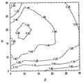
本出願人等は、コンピュータプログラムに対してベンチマークテストを行なうための実験データを使用して、100〜150kV用に最適化された電子顕微鏡法コンピュータコードに基づくモンテカルロ(Monte-Carlo) コンピュータプログラムシミュレーションを行なった。ベンチマークテストを行なったモンテカルロシミュレーションの結果は、y軸がα(すなわち、第1の角度26)を表わし、x軸がβ(すなわち、第2の角度34)を表わすX線エネルギー束増加を示すx−y等高線図として、図2に提示される。驚くべきことに、本出願人等は、増加が少なくとも1.5(すなわち、図2の囲まれた1.50の等高線の線上及び線内の領域)である「スイートスポット」を発見した。なお、15°未満のα(すなわち、第1の角度26)及び/又は5°未満のβ(すなわち、第2の角度34)でX線管を製造することが、機械的且つ設計上困難であることは、当業者には明らかなことであろう。また、9°のα及び7°のβを有する従来技術のX線管構成を、βをほぼ7°に保ちつつ、ほぼ20°のαを有するように変形することにより、機械的且つ設計上の困難を最小限に抑えつつ、図2及び図3により明らかなように、X線エネルギー束増加を結果として1.50近くできることにも留意すべきである。X線エネルギー束増加の改善を提供するより広範囲な設計の外囲器は、図2から明らかなように、適度の機械的再設計により、15°〜30°の範囲のα(第1の角度26)と、αよりも小さく且つ5°〜15°の範囲にあるβ(第2の角度)とを必要とする。図2の目盛りからは外れるが、本出願人等は、αが15°〜60°の範囲にあり、かつβがαより小さい場合、X線エネルギー束において向上が見られることを発見した。
【0017】
以上、例示の目的で、本発明の実施例の方法及び表現を説明してきた。以上の説明は、全てを網羅するものではなく、開示した形態のみに本発明を限定するものではない。多数の変形及び変更が可能であることは、上述の教示の観点から明らかである。本発明の趣旨の範囲は、添付の特許請求の範囲によって規定されるべきである。
【図面の簡単な説明】
【図1】本発明のX線管構体の実施例の概略図。
【図2】方位角が0°であり、幾本かの等高線が図面を明瞭にする目的で省略され、α及びβ(°で示される)の種々の値に対するX線エネルギー束増加を示す等高線図。
【図3】βが7°の場合のαの種々の値(°で示される)に対するX線エネルギー束増加を示す図。
【符号の説明】
10 X線管構体
12 X線管陽極
14 X線管陰極
16 X線管窓
18 X線発生ターゲット
20、28 表面
22 電子ビーム軸
24 焦点
26 第1の角度
30 中心点
32 線
34 第2の角度[0001]
BACKGROUND OF THE INVENTION
The present invention relates generally to x-ray tubes, and more particularly to x-ray tubes having a higher ratio of x-ray energy flux to power applied to a target.
[0002]
[Prior art]
X-ray devices used in the medical field are typically fixed by a cathode that is heated to emit a beam of electrons, an anode having a target (usually rotating) with one surface facing the cathode, and a window mount. And an X-ray tube including a glass and / or metal surrounding frame including an X-ray transmission window. Typically, the cathode is oriented so that electrons are incident on the focal point on the target surface at an angle of approximately 90 ° to the target surface. Part of the emitted electrons enter the target surface to generate X-rays, and part of the X-rays are emitted from the frame as an X-ray beam through the X-ray transmission window. Typically, the X-ray window is arranged to receive X-rays that are spaced from the target surface at an angle of approximately 7 ° with respect to the target surface. Some of the emitted electrons are backscattered without generating X-rays when they enter the target surface. Many of the backscattered electrons subsequently enter the frame including the X-ray transmission window and the window mounting portion, and heat the frame. The frame is also heated from the inside by other heat sources such as thermal radiation. The heated frame is typically cooled by a liquid refrigerant such as oil or water located between the frame and a surrounding casing having a dedicated X-ray transmission window.
[0003]
[Problems to be solved by the invention]
Less than approximately 1 percent of the power of electrons incident on the target surface is converted to x-ray power. Increasing the power of the electron beam will increase the x-ray power output of the tube. However, increasing the power of the electron beam results in an unacceptably high thermal load on the target, ultimately limiting the X-ray power output. What is needed is an x-ray tube assembly and method for generating x-rays to increase the ratio of x-ray tube power per target thermal load.
[0004]
[Means for Solving the Problems]
In the first embodiment of the present invention, the X-ray tube assembly includes an X-ray tube anode, an X-ray tube cathode and an X-ray tube window. The anode includes an X-ray generation target having a surface. The cathode has an electron beam axis. The electron beam axis intersects the target surface at the focal point and is directed at a first angle relative to the target surface. The first angle is in the range of 15 ° to 60 °. The window includes a surface having a center point, and a line connecting the focal point and the center point forms a second angle with respect to the target surface.
[0005]
In the second embodiment of the present invention, the X-ray tube assembly includes an X-ray tube anode, an X-ray tube cathode and an X-ray tube window. The anode includes an x-ray generating target having a surface. The cathode has an electron beam axis. The electron beam axis intersects the target surface at the focal point and is directed at a first angle relative to the target surface. The first angle is in the range of 15 ° to 60 °. The X-ray tube cathode generates electrons that produce X-rays having energy less than approximately 200 kV when incident on a target. The window includes a surface having a center point, and a line connecting the focal point and the center point forms a second angle with respect to the target surface. The second angle is smaller than the first angle. The electron beam axis and center point define a plane that is oriented substantially perpendicular to the target surface.
[0006]
The first method of the present invention is a method for generating X-rays and includes steps a) to c). Step a) includes generating an electron beam having an electron beam axis. Step b) directs the electron beam to be incident on the focal point on the surface of the X-ray generation target such that the electron beam axis makes a first angle in the range of 15 ° to 60 ° with the surface of the X-ray target. And generating X-rays. Step c) involves utilizing these X-rays that form a second angle with respect to the surface of the target.
[0007]
The second method of the present invention is a method for generating X-rays and includes steps a) to c). Step a) includes generating an electron beam having an electron beam axis. Step b) directs the electron beam to be incident on the focal point on the surface of the X-ray generation target such that the electron beam axis makes a first angle in the range of 15 ° to 60 ° with the surface of the X-ray target. And generating X-rays having energy less than approximately 200 kV. Step c) utilizes X-rays that form a second angle that is less than the first angle with respect to the target surface and that, together with the electron beam axis, define a plane that is oriented substantially perpendicular to the target surface. Including doing.
[0008]
In accordance with the present invention, a first angle (usually referred to as the electron beam incident angle, but here referred to as “α”) and a second angle (commonly referred to as the X-ray emission angle, here referred to as “β”). ) Provides several benefits and advantages. For example, computer benchmark simulations performed using experimental data show an increase in X-ray energy flux of approximately 1.5 when β is equal to 7 ° and α is equal to 15 ° to 20 °. This increase is calculated relative to the X-ray energy flux according to the prior art configuration where β is 7 ° and α is 9 °. In that comparison, the power applied to the target (ie, the thermal load measured by temperature) and the focus temperature of the target are the same in both the inventive configuration and the prior art configuration, and X of the inventive configuration. It will be apparent to those skilled in the art that the line spectra are filtered to obtain the same average photon (ie, x-ray) energy as prior art configurations for proper comparison. An increase of 1.5 means that the x-ray power output for the same heat load and the same focus temperature on the target of the present configuration increased by 50 percent compared to the prior art configuration. Also, the X-ray tube of the present configuration can be operated at the same X-ray power output and lower temperature (to extend the life of the tube) compared to the X-ray tube of the prior art configuration.
[0009]
DETAILED DESCRIPTION OF THE INVENTION
Referring now to the drawings, FIG. 1 schematically illustrates one embodiment of an
[0010]
In one design example, the
[0011]
In the second embodiment shown in FIG. 1, the
[0012]
The first method of the present invention is a method for generating X-rays and includes steps a) to c). Step a) includes generating an electron beam having an
[0013]
In one application of the first method of the present invention, the
[0014]
The second method of the present invention is a method for generating X-rays and includes steps a) to c). Step a) includes generating an electron beam having an
[0015]
Applicants have identified a first angle 26 (usually referred to as the electron beam incident angle, referred to herein as “α”) and a second angle 34 (usually referred to as the X-ray emission angle, where “ Several experiments were conducted to obtain data on the increase in X-ray energy flux for various values of [beta]. “Increase” refers to the X-ray energy flux for various values of the first angle and the second angle, where the
[0016]
Applicants have used Monte-Carlo computer program simulation based on electron microscopy computer code optimized for 100-150 kV using experimental data for benchmarking computer programs. I did it. The results of a Monte Carlo simulation with a benchmark test show an x-ray energy flux increase where the y axis represents α (ie, the first angle 26) and the x axis represents β (ie, the second angle 34). As a -y contour map, it is presented in FIG. Surprisingly, Applicants have discovered a “sweet spot” that has an increase of at least 1.5 (ie, on and within the enclosed 1.50 contour line of FIG. 2). It is difficult to manufacture an X-ray tube with an α of less than 15 ° (ie, the first angle 26) and / or a β of less than 5 ° (ie, the second angle 34) due to mechanical and design reasons. It will be apparent to those skilled in the art. Also, mechanically and designally, a prior art X-ray tube configuration having 9 ° α and 7 ° β is modified to have an α of approximately 20 ° while maintaining β at approximately 7 °. It should also be noted that an increase in X-ray energy flux can result in close to 1.50, as is apparent from FIGS. A more extensively designed envelope that provides an improvement in x-ray energy flux increases, as is apparent from FIG. 2, with moderate mechanical redesign, α (first angle) in the range of 15 ° -30 °. 26) and β (second angle) smaller than α and in the range of 5 ° to 15 °. Although not on the scale of FIG. 2, the present applicants have found that when α is in the range of 15 ° to 60 ° and β is smaller than α, an improvement in X-ray energy flux is observed.
[0017]
The foregoing has been a description of methods and representations of embodiments of the present invention for purposes of illustration. The above description is not exhaustive and does not limit the invention to the forms disclosed. Obviously, many modifications and variations are possible in view of the above teachings. The scope of the present invention should be defined by the appended claims.
[Brief description of the drawings]
FIG. 1 is a schematic view of an embodiment of an X-ray tube assembly of the present invention.
FIG. 2 is a contour line showing an increase in X-ray energy flux for various values of α and β (denoted in °), with an azimuth angle of 0 °, with some contour lines omitted for purposes of clarity of the drawing. Figure.
FIG. 3 is a diagram illustrating the increase in X-ray energy flux for various values of α (indicated in °) when β is 7 °.
[Explanation of symbols]
10
Claims (8)
b)電子ビーム軸を有するX線管陰極であって、前記電子ビーム軸が焦点において前記ターゲットの前記表面と交差し、また前記電子ビーム軸は前記ターゲットの前記表面に対して第1の角度で方向づけられており、前記第1の角度がほぼ20°であるX線管陰極と、
c)中心点を有する表面を含むX線管窓であって、前記焦点と前記中心点とを結ぶ線が、前記ターゲットの前記表面に対して第2の角度をなしており、前記第2の角度がほぼ7°であるX線管窓と、を具備するX線管構体。a) an X-ray tube anode comprising an X-ray generating target having a surface;
b) an X-ray tube cathode having an electron beam axis, wherein the electron beam axis intersects the surface of the target at a focal point, and the electron beam axis is at a first angle with respect to the surface of the target. An X-ray tube cathode that is oriented and wherein the first angle is approximately 20 ° ;
c) an X-ray tube window including a surface having a center point, wherein a line connecting the focal point and the center point forms a second angle with respect to the surface of the target ; An X-ray tube structure comprising: an X-ray tube window having an angle of approximately 7 ° .
b)電子ビーム軸を有し、且つ前記ターゲットに入射したときにほぼ200kV未満のエネルギーを有するX線を生じさせる電子を発生するするX線管陰極であって、前記電子ビーム軸が焦点において前記ターゲットの前記表面と交差し、また前記電子ビーム軸は前記ターゲットの前記表面に対して第1の角度で方向づけられており、前記第1の角度がほぼ20°であるX線管陰極と、
c) 中心点を有する表面を含むX線管窓であって、前記焦点と前記中心点とを結ぶ線が、前記ターゲットの前記表面に対してほぼ7°の第2の角度をなし、前記電子ビーム軸と前記中心点が、前記ターゲットの前記表面に対してほぼ垂直に方向づけられる平面を規定しているX線管窓と、を具備するX線管構体。a) an X-ray tube anode comprising an X-ray generating target having a surface;
b) an X-ray tube cathode that has an electron beam axis and generates electrons that produce X-rays having an energy of less than 200 kV when incident on the target, the electron beam axis at the focal point; An x-ray tube cathode that intersects the surface of the target and the electron beam axis is oriented at a first angle with respect to the surface of the target, the first angle being approximately 20 ° ;
An X-ray tube window including a surface having c) a center point, a line connecting the said center point and the focal point, without a second angle of approximately 7 ° relative to the surface of the target, the electronic An X-ray tube assembly comprising: a beam axis; and an X-ray tube window defining a plane in which the center point is oriented substantially perpendicular to the surface of the target.
a)電子ビーム軸を有する電子ビームを発生する過程と、
b)前記電子ビームを方向づけてX線発生ターゲットの表面上の焦点に入射させてX線を発生する過程であって、前記電子ビーム軸が前記ターゲットの前記表面に対してほぼ20°の第1の角度をなすようにした、当該X線を発生する過程と、
c)前記ターゲットの前記表面に対してほぼ7°の第2の角度をなすX線を利用する過程と、を含んでいる方法。In a method for generating X-rays,
a) generating an electron beam having an electron beam axis;
b) A process of directing the electron beam and causing it to enter a focal point on the surface of the X-ray generation target to generate X-rays, wherein the electron beam axis is a first angle approximately 20 ° with respect to the surface of the target. A process of generating the X-ray, which is configured to make an angle of
c) utilizing X-rays that form a second angle of approximately 7 ° with respect to the surface of the target.
a)電子ビーム軸を有する電子ビームを発生する過程と、
b)前記電子ビームを方向づけてX線発生ターゲットの表面上の焦点に入射させて、ほぼ200kV未満のエネルギーを有するX線を発生する過程であって、前記電子ビーム軸が前記ターゲットの前記表面に対してほぼ20°の第1の角度をなすようにした、当該X線を発生する過程と、
c)前記ターゲットの前記表面に対してほぼ7°の第2の角度をなし、かつ前記電子ビーム軸とともに、前記ターゲットの前記表面に対してほぼ垂直に方向づけられる平面を規定するこれらのX線を利用する過程と、を含んでいる方法。In a method for generating X-rays,
a) generating an electron beam having an electron beam axis;
b) directing the electron beam into a focal point on the surface of the X-ray generation target to generate X-rays having an energy of less than about 200 kV, wherein the electron beam axis is incident on the surface of the target Generating X-rays at a first angle of about 20 ° with respect to the X-rays;
c) These X-rays defining a plane that forms a second angle of approximately 7 ° with respect to the surface of the target and that, together with the electron beam axis, is oriented substantially perpendicular to the surface of the target. And a process comprising:
Applications Claiming Priority (2)
| Application Number | Priority Date | Filing Date | Title |
|---|---|---|---|
| US09/547242 | 2000-04-11 | ||
| US09/547,242 US6421422B1 (en) | 1999-08-25 | 2000-04-11 | Apparatus and method for increasing X-ray tube power per target thermal load |
Publications (3)
| Publication Number | Publication Date |
|---|---|
| JP2001297892A JP2001297892A (en) | 2001-10-26 |
| JP2001297892A5 JP2001297892A5 (en) | 2008-03-06 |
| JP4759148B2 true JP4759148B2 (en) | 2011-08-31 |
Family
ID=24183903
Family Applications (1)
| Application Number | Title | Priority Date | Filing Date |
|---|---|---|---|
| JP2001015167A Expired - Fee Related JP4759148B2 (en) | 2000-04-11 | 2001-01-24 | Apparatus and method for increasing x-ray tube power per target thermal load |
Country Status (2)
| Country | Link |
|---|---|
| EP (1) | EP1146542A1 (en) |
| JP (1) | JP4759148B2 (en) |
Families Citing this family (2)
| Publication number | Priority date | Publication date | Assignee | Title |
|---|---|---|---|---|
| JP5370965B2 (en) * | 2009-10-14 | 2013-12-18 | 株式会社東芝 | X-ray tube and X-ray tube device |
| JP6114981B2 (en) * | 2012-10-17 | 2017-04-19 | 株式会社リガク | X-ray generator |
Family Cites Families (15)
| Publication number | Priority date | Publication date | Assignee | Title |
|---|---|---|---|---|
| US3719846A (en) * | 1970-02-25 | 1973-03-06 | Philips Corp | X-ray tube |
| US4392235A (en) * | 1979-08-16 | 1983-07-05 | General Electric Company | Electronically scanned x-ray tomography system |
| US4309637A (en) * | 1979-11-13 | 1982-01-05 | Emi Limited | Rotating anode X-ray tube |
| JPS5859546A (en) * | 1981-10-02 | 1983-04-08 | Toshiba Corp | Rotary-anode-type x-ray tube |
| JPS60254538A (en) * | 1984-05-31 | 1985-12-16 | Toshiba Corp | X-ray tube device |
| JPS6224543A (en) * | 1985-07-24 | 1987-02-02 | Toshiba Corp | X-ray tube apparatus |
| US5029195A (en) * | 1985-08-13 | 1991-07-02 | Michael Danos | Apparatus and methods of producing an optimal high intensity x-ray beam |
| JPH01134842A (en) * | 1987-11-19 | 1989-05-26 | Mitsubishi Heavy Ind Ltd | X-ray generating device |
| US5128977A (en) * | 1990-08-24 | 1992-07-07 | Michael Danos | X-ray tube |
| US5206895A (en) * | 1990-08-24 | 1993-04-27 | Michael Danos | X-ray tube |
| DE4228559A1 (en) * | 1992-08-27 | 1994-03-03 | Dagang Tan | X-ray tube with a transmission anode |
| DE19509006C2 (en) * | 1995-03-13 | 1998-11-05 | Siemens Ag | X-ray tube |
| DE19513289C2 (en) * | 1995-04-07 | 1998-05-14 | Siemens Ag | X-ray tube with an adjustment unit |
| DE19627025C2 (en) * | 1996-07-04 | 1998-05-20 | Siemens Ag | X-ray tube |
| US5751784A (en) * | 1996-09-27 | 1998-05-12 | Kevex X-Ray | X-ray tube |
-
2001
- 2001-01-23 EP EP01300568A patent/EP1146542A1/en not_active Ceased
- 2001-01-24 JP JP2001015167A patent/JP4759148B2/en not_active Expired - Fee Related
Also Published As
| Publication number | Publication date |
|---|---|
| EP1146542A1 (en) | 2001-10-17 |
| JP2001297892A (en) | 2001-10-26 |
Similar Documents
| Publication | Publication Date | Title |
|---|---|---|
| EP2740332B1 (en) | Radiation generating apparatus and radiation imaging apparatus | |
| US7197116B2 (en) | Wide scanning x-ray source | |
| TWI307110B (en) | Method and apparatus for controlling electron beam current | |
| US8175222B2 (en) | Electron emitter and method of making same | |
| JPH103872A (en) | Cathode for focusing electron of x-ray tube, cathode assembly for focusing electron beam, and method for changing dimension of focus of electron beam | |
| US9514911B2 (en) | X-ray tube aperture body with shielded vacuum wall | |
| US9530528B2 (en) | X-ray tube aperture having expansion joints | |
| JPH11273597A (en) | X-ray tube | |
| WO2013032019A1 (en) | X-ray generator and x-ray imaging apparatus | |
| CN103219211B (en) | X-ray source and X ray production method | |
| CN104037042A (en) | X-ray Generation Tube, X-ray Generation Device, And X-ray Imaging System | |
| JP2013051154A (en) | Transmission x-ray generator and x-ray imaging device using the same | |
| US9048064B2 (en) | Cathode assembly for a long throw length X-ray tube | |
| TWI399780B (en) | X-ray source comprising a field emission cathode | |
| US8000450B2 (en) | Aperture shield incorporating refractory materials | |
| JP4759148B2 (en) | Apparatus and method for increasing x-ray tube power per target thermal load | |
| US6421422B1 (en) | Apparatus and method for increasing X-ray tube power per target thermal load | |
| CN117038419A (en) | Carbon nanotube cold cathode micro-focus X-ray tube | |
| US10032595B2 (en) | Robust electrode with septum rod for biased X-ray tube cathode | |
| US20060050851A1 (en) | Shield structure for x-ray device | |
| JP2011233365A (en) | Rotating anode x-ray tube and rotating anode x-ray tube assembly | |
| JP5437262B2 (en) | X-ray tube having a focal position close to the tube end | |
| US8867706B2 (en) | Asymmetric x-ray tube | |
| Choi et al. | Development of new X-ray source based on carbon nanotube field emission and application to the non destructive imaging technology | |
| US8270571B2 (en) | Radiation source, imaging system, and operating method to determine and produce a radiation focal spot having an asymmetrical power input profile |
Legal Events
| Date | Code | Title | Description |
|---|---|---|---|
| A521 | Request for written amendment filed |
Free format text: JAPANESE INTERMEDIATE CODE: A523 Effective date: 20080121 |
|
| A621 | Written request for application examination |
Free format text: JAPANESE INTERMEDIATE CODE: A621 Effective date: 20080121 |
|
| A131 | Notification of reasons for refusal |
Free format text: JAPANESE INTERMEDIATE CODE: A131 Effective date: 20101102 |
|
| RD02 | Notification of acceptance of power of attorney |
Free format text: JAPANESE INTERMEDIATE CODE: A7422 Effective date: 20101115 |
|
| RD04 | Notification of resignation of power of attorney |
Free format text: JAPANESE INTERMEDIATE CODE: A7424 Effective date: 20101115 |
|
| A521 | Request for written amendment filed |
Free format text: JAPANESE INTERMEDIATE CODE: A523 Effective date: 20110106 |
|
| RD02 | Notification of acceptance of power of attorney |
Free format text: JAPANESE INTERMEDIATE CODE: A7422 Effective date: 20110106 |
|
| RD04 | Notification of resignation of power of attorney |
Free format text: JAPANESE INTERMEDIATE CODE: A7424 Effective date: 20110106 |
|
| A01 | Written decision to grant a patent or to grant a registration (utility model) |
Free format text: JAPANESE INTERMEDIATE CODE: A01 Effective date: 20110524 |
|
| A01 | Written decision to grant a patent or to grant a registration (utility model) |
Free format text: JAPANESE INTERMEDIATE CODE: A01 |
|
| A61 | First payment of annual fees (during grant procedure) |
Free format text: JAPANESE INTERMEDIATE CODE: A61 Effective date: 20110606 |
|
| R150 | Certificate of patent or registration of utility model |
Free format text: JAPANESE INTERMEDIATE CODE: R150 |
|
| FPAY | Renewal fee payment (event date is renewal date of database) |
Free format text: PAYMENT UNTIL: 20140610 Year of fee payment: 3 |
|
| LAPS | Cancellation because of no payment of annual fees |