JP5437262B2 - X-ray tube having a focal position close to the tube end - Google Patents
X-ray tube having a focal position close to the tube end Download PDFInfo
- Publication number
- JP5437262B2 JP5437262B2 JP2010535074A JP2010535074A JP5437262B2 JP 5437262 B2 JP5437262 B2 JP 5437262B2 JP 2010535074 A JP2010535074 A JP 2010535074A JP 2010535074 A JP2010535074 A JP 2010535074A JP 5437262 B2 JP5437262 B2 JP 5437262B2
- Authority
- JP
- Japan
- Prior art keywords
- anode
- ray tube
- cathode
- vacuum
- disposed
- Prior art date
- Legal status (The legal status is an assumption and is not a legal conclusion. Google has not performed a legal analysis and makes no representation as to the accuracy of the status listed.)
- Active
Links
- 238000009607 mammography Methods 0.000 claims description 29
- 238000000034 method Methods 0.000 claims description 24
- 210000000779 thoracic wall Anatomy 0.000 claims description 20
- 238000002955 isolation Methods 0.000 claims description 7
- 239000007770 graphite material Substances 0.000 claims 5
- 210000000038 chest Anatomy 0.000 description 16
- 238000003384 imaging method Methods 0.000 description 15
- 230000008901 benefit Effects 0.000 description 7
- 230000000694 effects Effects 0.000 description 7
- 239000000463 material Substances 0.000 description 7
- OKTJSMMVPCPJKN-UHFFFAOYSA-N Carbon Chemical compound [C] OKTJSMMVPCPJKN-UHFFFAOYSA-N 0.000 description 6
- 229910002804 graphite Inorganic materials 0.000 description 6
- 239000010439 graphite Substances 0.000 description 6
- 239000002826 coolant Substances 0.000 description 4
- 230000005855 radiation Effects 0.000 description 4
- 239000000919 ceramic Substances 0.000 description 3
- 239000000758 substrate Substances 0.000 description 3
- 210000000481 breast Anatomy 0.000 description 2
- 238000001514 detection method Methods 0.000 description 2
- 238000010586 diagram Methods 0.000 description 2
- 238000005516 engineering process Methods 0.000 description 2
- RYGMFSIKBFXOCR-UHFFFAOYSA-N Copper Chemical compound [Cu] RYGMFSIKBFXOCR-UHFFFAOYSA-N 0.000 description 1
- ZOKXTWBITQBERF-UHFFFAOYSA-N Molybdenum Chemical compound [Mo] ZOKXTWBITQBERF-UHFFFAOYSA-N 0.000 description 1
- 230000003044 adaptive effect Effects 0.000 description 1
- 239000000956 alloy Substances 0.000 description 1
- 229910045601 alloy Inorganic materials 0.000 description 1
- 238000004458 analytical method Methods 0.000 description 1
- 230000000712 assembly Effects 0.000 description 1
- 238000000429 assembly Methods 0.000 description 1
- 230000009286 beneficial effect Effects 0.000 description 1
- 238000002591 computed tomography Methods 0.000 description 1
- 238000001816 cooling Methods 0.000 description 1
- 239000012809 cooling fluid Substances 0.000 description 1
- 229910052802 copper Inorganic materials 0.000 description 1
- 239000010949 copper Substances 0.000 description 1
- 230000005672 electromagnetic field Effects 0.000 description 1
- 230000005670 electromagnetic radiation Effects 0.000 description 1
- 239000011521 glass Substances 0.000 description 1
- 239000007788 liquid Substances 0.000 description 1
- 238000004519 manufacturing process Methods 0.000 description 1
- 229910052751 metal Inorganic materials 0.000 description 1
- 239000002184 metal Substances 0.000 description 1
- 239000000203 mixture Substances 0.000 description 1
- 229910052750 molybdenum Inorganic materials 0.000 description 1
- 239000011733 molybdenum Substances 0.000 description 1
- 238000001959 radiotherapy Methods 0.000 description 1
- DECCZIUVGMLHKQ-UHFFFAOYSA-N rhenium tungsten Chemical compound [W].[Re] DECCZIUVGMLHKQ-UHFFFAOYSA-N 0.000 description 1
- 239000004065 semiconductor Substances 0.000 description 1
- 238000003325 tomography Methods 0.000 description 1
- WFKWXMTUELFFGS-UHFFFAOYSA-N tungsten Chemical compound [W] WFKWXMTUELFFGS-UHFFFAOYSA-N 0.000 description 1
- 229910052721 tungsten Inorganic materials 0.000 description 1
- 239000010937 tungsten Substances 0.000 description 1
- 238000004846 x-ray emission Methods 0.000 description 1
Images


Classifications
-
- H—ELECTRICITY
- H01—ELECTRIC ELEMENTS
- H01J—ELECTRIC DISCHARGE TUBES OR DISCHARGE LAMPS
- H01J35/00—X-ray tubes
- H01J35/24—Tubes wherein the point of impact of the cathode ray on the anode or anticathode is movable relative to the surface thereof
- H01J35/26—Tubes wherein the point of impact of the cathode ray on the anode or anticathode is movable relative to the surface thereof by rotation of the anode or anticathode
Landscapes
- Apparatus For Radiation Diagnosis (AREA)
- X-Ray Techniques (AREA)
Description
本発明は、通常のX線管に関する。特に、本発明の実施形態は、アノードの焦点位置と、アノードが配置された真空筐体の近接した端部との間の距離を縮小するX線管の構成を示す。 The present invention relates to a normal X-ray tube. In particular, embodiments of the present invention show an X-ray tube configuration that reduces the distance between the focal position of the anode and the close end of the vacuum housing where the anode is located.
X線生成装置は、産業及び医療の両方の広範囲の種々のアプリケーションに用いられる極めて有用なツールである。例えば、このような装置は、医療の診断上の検査、放射線治療、半導体製造、及び材料分析等の分野に共通に用いられる。 X-ray generators are extremely useful tools used in a wide variety of applications, both industrial and medical. For example, such devices are commonly used in fields such as medical diagnostic examination, radiation therapy, semiconductor manufacturing, and material analysis.
X線生成装置は、このようなアプリケーションに用いられるにもかかわらず、同様な構成にて動作する。X線生成装置は、通常、電子を放射して加速させ、固有の組成の材料に衝突するときにX線を生成する。この工程は、X線生成装置に配置されたX線管において実行する。X線管は、通常、真空筐体、カソード、及びアノードを含む。電子放射のためのフィラメントを有するカソードは、カソードにより放射された電子を受け取るようにアノードが配向されている真空筐体内に配置される。 The X-ray generation apparatus operates in the same configuration even though it is used for such an application. An X-ray generator usually emits electrons and accelerates them to generate X-rays when they collide with a material having a specific composition. This process is executed in an X-ray tube arranged in the X-ray generation apparatus. An x-ray tube typically includes a vacuum housing, a cathode, and an anode. A cathode having a filament for electron emission is placed in a vacuum housing in which the anode is oriented to receive electrons emitted by the cathode.
真空筐体は、銅等の金属、ガラス、セラミック、又はこれらの組み合わせにより構成され、通常、外側ハウジング内に配置される。X線の進行を可能する窓領域は別として、外側ハウジングは、通常、シールド層(例えば、鉛又は同様なX線を減少する材質により構成される)により被覆され、真空筐体にて生成されるX線の漏洩を防止する。他に、外側ハウジングと真空筐体との間に存在する容量に絶縁油又は同様の冷却材等の冷却媒体を配置することができ、真空筐体の表面から熱放散する。このような構成に基づいて、熱は、ポンプや液体導管を介して外部変換器に冷却剤を循環させることにより冷却材から除去可能である。 The vacuum housing is made of a metal such as copper, glass, ceramic, or a combination thereof, and is usually disposed in the outer housing. Apart from the window area that allows X-rays to travel, the outer housing is usually covered with a shield layer (eg, composed of lead or similar X-ray reducing material) and is produced in a vacuum enclosure. Prevent X-ray leakage. In addition, a cooling medium such as insulating oil or similar coolant can be disposed in a capacity existing between the outer housing and the vacuum housing, and heat is dissipated from the surface of the vacuum housing. Based on such a configuration, heat can be removed from the coolant by circulating a coolant to the external transducer via a pump or liquid conduit.
動作時に、電流は、カソードのフィラメントに供給され、電子流は、熱イオン放射により放射される。電子流が運動エネルギーを得てアノードに配置されるターゲット表面に向かって加速するための、カソードとアノードとの間の電位が確立される。ターゲット表面への衝突の結果より生じる運動エネルギーが、例えばX線等の極めて高周波数の電磁放射線に変換される。 In operation, current is supplied to the cathode filament and the electron stream is emitted by thermionic radiation. A potential is established between the cathode and anode for the electron stream to gain kinetic energy and accelerate towards the target surface located at the anode. The kinetic energy resulting from the impact on the target surface is converted into extremely high frequency electromagnetic radiation, for example X-rays.
生成されるX線の固有の周波数は、アノードのターゲット表面を形成するために使用される材質の種類に少なくとも部分的に依存する。高い原子番号(”Z”)を有するターゲット表面の材質は、一般的に使用され、所望のアプリケーション及びX線の特性に基づいて選択される。その結果、X線は、X線装置から所定の真空筐体及び外側ハウジングを介して患者等のX線対象に到達するように視準可能となる。 The inherent frequency of the generated x-rays depends at least in part on the type of material used to form the anode target surface. Target surface materials with high atomic numbers ("Z") are commonly used and are selected based on the desired application and x-ray characteristics. As a result, X-rays can be collimated from the X-ray apparatus so as to reach an X-ray target such as a patient via a predetermined vacuum housing and outer housing.
マンモグラフィーの分野に用いられる特有の管等のX線管の動作に関する試みは、X線撮影中に患者の体(特に、患者の体の対象部分)に対応する管の最適な位置に関する。例えば、マンモグラフィーを実行する場合、X線管の焦点位置、例えばカソードにより放射されて焦点が合わされた電子が衝突するアノードのターゲット表面上の位置を、胸壁に可能な限り近づけるように配置することは、有効である。このような配置は、X線ビームの撮影における不均一性を生じさせるアノードに基づくX線撮影の特徴である「ヒール効果」を克服して、胸の組織を可能な限り正確に撮影可能であるという点で好ましい。反対に、焦点位置は、胸壁から比較的大きく離れた距離に配置されると、結果として画像品質が悪化する。 Attempts regarding the operation of X-ray tubes, such as specific tubes used in the field of mammography, relate to the optimal position of the tube corresponding to the patient's body (especially the target portion of the patient's body) during X-ray imaging. For example, when performing mammography, placing the focal position of the X-ray tube, for example, the position on the target surface of the anode where the focused electrons emitted by the cathode collide as close as possible to the chest wall is not possible. ,It is valid. Such an arrangement overcomes the “heel effect” that is characteristic of anode-based X-ray imaging, which causes non-uniformities in X-ray beam imaging, and allows breast tissue to be imaged as accurately as possible. This is preferable. On the other hand, if the focal position is located at a relatively large distance from the chest wall, the image quality will deteriorate as a result.
上記にもかかわらず、公知の管の設計では、胸壁とアノードの焦点との間の間隔が最小となるように構成されない。特に、公知の管の設計では、通常、アノードと真空筐体の最も近い端壁との間に介在されるカソードアセンブリの一部又は全てを用いて構成される。このような構成は、いくつかの点において有益であるが、それにもかかわらず、焦点位置の配置を胸壁に好ましくは近づけることの妨げとなる。 Despite the above, known tube designs are not configured to minimize the spacing between the chest wall and the anode focus. In particular, known tube designs are typically constructed using some or all of the cathode assembly interposed between the anode and the nearest end wall of the vacuum housing. Such a configuration is beneficial in several respects, but nevertheless prevents the focal position placement from being preferably close to the chest wall.
上記の撮影に関する試みは、胸部や撮影の対象が比較的大きい場合に公知の管の設計を悪化させ、それにより、対応するアノードのターゲット表面の大きな焦点軌道角度を用いる必要があることを示唆する。大きな焦点軌道角度を用いることは、焦点のサイズを望ましくなく増加させて、従って、いずれのマンモグラフィーのアプリケーションに対しても望ましくない。 The above shoot-related attempts impair the known tube design when the breast or shoot is relatively large, thereby suggesting that a large focal trajectory angle of the corresponding anode target surface should be used. . Using a large focal trajectory angle undesirably increases the size of the focal point and is therefore undesirable for any mammographic application.
さらに、高電圧の管、例えば、50kVより大きな実行電圧を有する管は、胸壁と焦点位置との間隔が増大する。特に、X線管の実行電圧が増大すると、アノードとカソードとの間隔の必要条件は、必然的に増加し、適切な電圧絶縁間隔を提供する。この増大したカソードとアノードのターゲット表面との間隔は、ターゲット表面上の焦点位置からX線管の最も近い端部までの距離に対応して増大し、それにより、このような患者の胸壁では、上記の望ましくない影響が生じる。 Furthermore, high voltage tubes, such as tubes having an effective voltage greater than 50 kV, increase the spacing between the chest wall and the focal position. In particular, as the effective voltage of the x-ray tube increases, the spacing requirement between the anode and cathode inevitably increases, providing a suitable voltage isolation spacing. This increased cathode-to-anode target surface spacing increases corresponding to the distance from the focal position on the target surface to the closest end of the x-ray tube, so that in such a patient's chest wall, The above undesirable effects occur.
本発明は、当該技術において上記及び他に必要とされることを考慮して発明された。要するに、本発明の実施形態は、アノードの焦点位置とアノードが配置される真空筐体の隣接した端壁との縮小した間隔を有するX線管を示す。他の利点では、縮小した間隔は、マンモグラフィー(又は同様)工程において患者の胸壁に相対的に近くにX線管を配置することができて、結果として、組織の範囲及び撮影結果が向上する。 The present invention was invented in view of the above and other needs in the art. In summary, embodiments of the present invention show an x-ray tube having a reduced spacing between the focal position of the anode and the adjacent end wall of the vacuum housing where the anode is located. Another advantage is that the reduced spacing allows the x-ray tube to be placed relatively close to the patient's chest wall in a mammography (or similar) process, resulting in improved tissue coverage and imaging results.
一実施形態では、マンモグラフィー又は他の撮影アプリケーションのためのX線管が開示される。X線管は、第1端部及び第2端部を有する真空筐体を含む。真空筐体は、回転式のアノードを支持するローターアセンブリを含む。アノードは、ターゲット表面及び反対側の第2表面を含む。開示された実施形態では、ターゲット表面は、軸受けアセンブリに向かって配向され、一方、第2表面は、真空筐体の第1端部に向かって配向される。好ましくは、アノードの第2表面と真空筐体の第1端部との間に介在構造はない。 In one embodiment, an x-ray tube for mammography or other imaging applications is disclosed. The x-ray tube includes a vacuum housing having a first end and a second end. The vacuum housing includes a rotor assembly that supports a rotating anode. The anode includes a target surface and an opposite second surface. In the disclosed embodiment, the target surface is oriented towards the bearing assembly, while the second surface is oriented towards the first end of the vacuum housing. Preferably, there is no intervening structure between the second surface of the anode and the first end of the vacuum housing.
カソードヘッドを有するカソードアセンブリが含まれ、カソードヘッドには、カソードヘッド内にフィラメントが配置される。フィラメントは、フィラメントから放射される電子がアノードの焦点軌道の焦点位置に衝突するように配向される。 A cathode assembly having a cathode head is included in which the filament is disposed within the cathode head. The filament is oriented so that electrons emitted from the filament strike the focal position of the focal path of the anode.
一般的なX線管構成では、カソードアセンブリは、アノードと真空筐体の第1端部との間に配置される。反対に、開示されたX線管の実施形態は、アノードの軸受けアセンブリと同じ側にカソードが配置されるように構成される。このことは、アノードの第2表面と真空筐体の第1端部との間に介在構造が存在しないことを実質的に確実にし、それにより、第1端部とアノードの焦点位置との間の物理的距離を縮小可能である。このように構成されると、X線管は、マンモグラフィーの撮影工程を経験する患者の胸壁に対して焦点位置が一般的な管構成より相対的に近づくように配置可能である。このことは、胸部のサイズに関係なく、X線適応範囲及び胸部組織の画像解像度を向上することができて、胸壁範囲の画像を向上することができる。 In a typical x-ray tube configuration, the cathode assembly is disposed between the anode and the first end of the vacuum housing. Conversely, the disclosed x-ray tube embodiments are configured such that the cathode is disposed on the same side of the anode bearing assembly. This substantially ensures that there are no intervening structures between the second surface of the anode and the first end of the vacuum housing, so that there is no gap between the first end and the focal position of the anode. The physical distance can be reduced. When configured in this way, the X-ray tube can be positioned such that the focal position is relatively closer to the chest wall of the patient undergoing the mammography imaging process than a general tube configuration. This can improve the X-ray adaptive range and the image resolution of the chest tissue regardless of the size of the chest, and can improve the image of the chest wall range.
本発明の例示的な実施形態では、アノードを接地したX線管構成が焦点位置と筐体の端壁との間隔をさらに縮小するように利用可能である。さらに、アノードの焦点軌道角度は縮小可能であり、これにより、焦点位置全体のサイズが縮小される。代替的な実施形態では、アノードの厚さは、端壁に対する間隔をさらに縮小するように変更可能である。 In an exemplary embodiment of the invention, an anode grounded x-ray tube configuration can be utilized to further reduce the spacing between the focal position and the end wall of the housing. Furthermore, the focal trajectory angle of the anode can be reduced, thereby reducing the size of the entire focal position. In an alternative embodiment, the anode thickness can be varied to further reduce the spacing to the end walls.
開示された実施形態は、焦点位置と対象の範囲との間隔を縮小することより利点を得るX線アプリケーションに関して利用可能であるが、明細書において開示された技術は、マンモグラフィーの分野に特に利用される。さらに、開示された実施形態は、標準的なアナログフィルム撮影機又はフラットパネルデジタル撮影機のいずれかに利用されるマンモグラム装置に関して有効である。明細書において開示された技術は、新規な、いわゆるマンモCT(胸部撮影のためのコンピュータ断層撮影)装置及びアプリケーションに関する重要な利点を提供する。 Although the disclosed embodiments are available for X-ray applications that benefit from reducing the distance between the focal position and the range of interest, the techniques disclosed herein are particularly utilized in the field of mammography. The Furthermore, the disclosed embodiments are useful with mammogram devices that are utilized in either standard analog film cameras or flat panel digital cameras. The technology disclosed in the specification provides significant advantages with respect to new, so-called mammo CT (Computer Tomography for Chest Imaging) devices and applications.
この要約は、詳細な説明にさらに後述される簡潔な構成における選択的な概念の紹介を提供する。この要約は、クレームに記載された対象のキーとなる特徴及び必須の特徴を確定することを意図せず、クレームに記載された対象範囲の決定を支援するように用いることを意図しない。 This summary provides an introduction to selective concepts in a concise configuration that is further described below in the detailed description. This summary is not intended to identify key features or essential features of the subject matter recited in the claims, nor is it intended to be used to assist in determining the subject matter recited in the claims.
追加の特徴は後述され、一部は、その説明から明白であり、又は明細書中の教示を実行することにより理解される。発明の効果は、添付した請求項にて特に指摘された装置及び組合せの方法により理解され、かつ、入手される。本発明の特徴は、以下の説明及び添付した請求項から完全に明白であり、又、後述の発明を実行することにより理解される。 Additional features are described below, some of which will be apparent from the description or will be understood by implementing the teachings herein. The advantages of the invention will be realized and obtained by means of the devices and combinations particularly pointed out in the appended claims. The features of the invention will be fully apparent from the following description and appended claims, and may be learned by the practice of the invention described hereinafter.
構造等が参照指定等をされる図を参照する。図は、発明の好適な実施形態の図形及び概略的な表現であること、本発明を制限しないこと、又、スケールに関して必ず描写しないことを理解し得る。 Refer to the figure in which the structure is designated for reference. It will be understood that the figures are graphical and schematic representations of preferred embodiments of the invention, do not limit the invention, and are not necessarily drawn with respect to scale.
図1〜図4は、本発明の実施形態の種々の特徴が描写され、回転式のアノードの電子焦点位置とX線管の最も近い端部との間の距離を縮小するように構成されたX線管を示す。この構成は、マンモグラフィー工程において患者の胸壁に対して相対的に近くにX線管を配置可能であり、それにより、管より放射される中心線は、胸壁に対して実質的に平行となる。この構成及び配置は、開示された実施形態の構成により、胸部のサイズに関係なく、マンモグラフィーの撮影が向上して公知のX線管の設計において一般的に遭遇する“ヒール効果”による撮影の問題が最小化される。本発明の実施形態は、高出力の管を有する種々の構成のX線管を含む。 1-4 depict various features of embodiments of the present invention and are configured to reduce the distance between the electron focus position of the rotating anode and the closest end of the x-ray tube. An X-ray tube is shown. This arrangement allows the x-ray tube to be placed relatively close to the patient's chest wall during the mammography process, so that the centerline emitted from the tube is substantially parallel to the chest wall. This configuration and arrangement is due to the "heel effect" commonly encountered in known x-ray tube designs with improved mammography imaging, regardless of chest size, due to the configuration of the disclosed embodiments. Is minimized. Embodiments of the present invention include various configurations of x-ray tubes having high power tubes.
マンモグラフィーを撮影するアプリケーションについて注目して明細書において説明するが、本発明の実施形態は、出力、サイズ、電圧/接地方法、及び使用目的の点にて種々の構成を有し、マンモグラフィーに制限されない。加えて、マンモグラフィーの分野では、開示された実施形態は、一般的なアナログフィルム撮影器又はフラットパネルデジタル撮影器のいずれかを利用するマンモグラフィーに関して有効である。明細書に開示された技術は、新規な、いわゆるマンモCT(胸部撮影のためのコンピュータ断層撮影)装置及びアプリケーションに対する重要な利点を提供する。 While an application for taking mammography is described in the specification with particular attention, embodiments of the present invention have various configurations in terms of power, size, voltage / grounding method, and intended use and are not limited to mammography. . In addition, in the field of mammography, the disclosed embodiments are useful for mammography that utilizes either a typical analog film photographer or a flat panel digital photographer. The technology disclosed in the specification provides significant advantages over new, so-called mammo CT (computerized tomography for chest imaging) devices and applications.
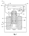
まず図1を参照し、本発明の例示的な一実施形態を示す。特に、図1は、X線生成装置の一例として提供され、10にて指定されたX線管を示す。X線管10は、カソードアセンブリ50及びアノードアセンブリ100を収容する真空筐体20を含み、真空筐体20は、明細書において“挿入部”として参照される。真空筐体20は、カソード及びアノードアセンブリ50,100、及び管10の真空中の他の重要な構成を収容するために必要な枠を形成し、かつ、提供する。図1の例示的な実施形態では、真空筐体20は、互いに密閉された第1部分20A及び第2部分20Bによりさらに画定されて筐体を形成する。他の実施形態では、排気筐体は、2つの部分以上により形成されるか、又は一体的に形成可能である。
Referring initially to FIG. 1, an exemplary embodiment of the present invention is shown. In particular, FIG. 1 shows an X-ray tube designated as 10 provided as an example of an X-ray generator. The
真空筐体は、望ましくないX線放射をシールドすること、及び適切なX線管の動作のために必要な冷却を提供することを支援する外側ハウジング30内に配置される。他の実施形態では、外側ハウジングは省略され、X線シールドが真空筐体の構造内に組込まれる。他の実施形態では、X線シールドは、他の所定の位置を除き、真空筐体又は外側ハウジングのいずれも含まれない。
The vacuum enclosure is placed in an
上記したように、カソード50は、管の動作中に電子62(図2)を生成するための電子ソースとして機能するフィラメント(図示せず)等の放射部を含む。このように、フィラメントは、好適には電源(図示せず)に接続され、十分な電流が供給されて高エネルギー電子62の生成を可能にする。
As described above, the
図1及び図2に関して、アノードアセンブリ100は、カソード50により生成される電子62を受け取り、管10からの放射のために電子の衝突に起因するエネルギーをX放射線又はX線64に変換する。例示的な実施形態では、アノードアセンブリ100は、基板106を有するアノード104を含み、基板106は、基板106の表面に配置されたターゲット表面110及び反対側の第2表面111を含む。特有の実施形態及びアプリケーションでは、ターゲット表面112は、モリブデン、タングステン、タングステン・レニウム、又は同様な合金を好ましくは含む。ターゲット表面112の所定の部分は、カソード50のフィラメントにより放射された電子流62がターゲット表面上に衝突するように配置され、結果として、X線の放射窓66(図2)を介して真空筐体20から放射するX線64を生成する。
With reference to FIGS. 1 and 2, the
明細書中に説明されたX線の生成は、比較的非効率であり、多量の熱が発生し、アノードアセンブリは、管の動作中にアノードから熱の除去が可能となるように構成可能であり、例えば、空気又は冷却流体の循環、又は上記した構造の真空筐体20を用いる。しかしながら、上記の詳細にもかかわらず、アノードアセンブリの構造及び構成は、本発明の請求項の範囲内で、明細書中に説明されたものから変更可能である。
The generation of X-rays described in the specification is relatively inefficient, a large amount of heat is generated, and the anode assembly can be configured to allow heat removal from the anode during tube operation. Yes, for example, the circulation of air or cooling fluid, or the
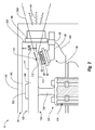
図1とともに、例示的なX線管10に関する詳細を示す図2に注目する。より詳細には、アノード104は、支持柱122、軸受けアセンブリ124、及びロータースリーブ128を通常含むローターアセンブリ120により支持される。支持柱122は、アノード104が軸受けアセンブリ124を介して支持柱に対して回転可能に配置されるように真空筐体20の部分に確実に固定され、それにより、アノードが支持柱に対して回転可能となる。
Attention is directed to FIG. 2 along with FIG. 1 showing details regarding an
ステータ134は、ロータースリーブ128に対して外周に配置される。公知のように、ステータ134は、回転電磁場を利用して、ロータースリーブ128を回転させる。ロータースリーブ128は、ローターステム130を介してアノード104に確実に固定される。図1及び図2に示すように、ローターステム130は、真空筐体20内で所定の高さ及び方向にてアノードを支持する。例示的な実施形態では、埋め込み式のナット132等の緊締用具は、ローターステム130とアノード104との間の結合部分を固定するように使用される。
The
上記のように、アノード104は、基板106及びターゲット表面110を含む。焦点軌道(focal track)112は、アノードのターゲット表面110のフラストコニカル(frustoconical)部分上に含まれる。焦点位置114は、カソードアセンブリ50により放射される電子62が焦点軌道上に衝突する位置として焦点軌道112上に画定される。図2は、焦点位置114と真空筐体の第1部分20Aの最も近い第1端壁140との間に距離として定義される距離ΔHを示す。
As described above, the
本発明の実施形態に従って、X線管10内の距離ΔHは、望ましくは最小となり、公知のX線管における対応する距離より実質的に短い値を有する。これを達成するため、X線管は、図2に例示的に示すように構成される。特に、アノード104は、焦点軌道112が公知のアノードの構成とは反対にX線管10の配置に応じて下側を向くように、真空筐体の第1部分20A内に配向される。
In accordance with an embodiment of the present invention, the distance ΔH in the
上記のようにアノード104の配置に合わせて、カソードアセンブリ50は、真空筐体の第1部分20Aの側壁144部分より延出するように配置される。このことは、カソードアセンブリが真空筐体の第1端壁140より延出する一般的な実施形態とは完全に反対である。図2に示すように、この例示的な配向は、カソードアセンブリから放射される電子62が焦点軌道112の焦点位置114に衝突するために適切に配向するようにカソードアセンブリ50を配置するようになされている。
As described above, the
より詳細に、カソードアセンブリ50は、前述したように、X線64を生成するための電子流62を供給する。カソードアセンブリ50は、カソードヘッド56を支持する支持構造54を含む。フィラメント60等の電子放射部は、カソードヘッド56に含まれる。カソードヘッド56は、熱イオン放射を用いてフィラメント60により生成された電子62が焦点軌道112の焦点位置114に衝突するようにアノード104に対応して配置される。同時に、カソードアセンブリ50は、十分な電圧隔離絶縁を供給するために、アノード104から十分に離れた間隔を空けなければならない。セラミックのフィードスルー58又は他の適切な絶縁構造は、真空筐体20の側壁44に提供され、X線管10の動作中に真空筐体からカソードアセンブリ50を電気的に絶縁する。
More specifically, the
説明すると、図2にそれぞれ示すように、例示的な実施形態では、カソードアセンブリ50は、真空筐体の側壁144において窓66の下側の位置から延出する。しかしながら、他の実施形態では、特有のアプリケーションが望まれるか又は必要とされる場合、カソードアセンブリ50は、真空筐体において窓66に対する他の位置から延出可能である。また説明すると、X線管10により生成されたX線64は、焦点位置114から放射され、コニカルパターンの窓66を通過し、X線コーン(cone)64Aも同様である。
To illustrate, in each exemplary embodiment, the
上記したようにX線管10内のカソードアセンブリ50の配置は、アノード104のターゲット表面110、又は軸受けアセンブリ124のような同じ側にカソードアセンブリを配置する。このような構成により、アノード104と真空筐体の第1端壁140との間に介在構造が含まれない。このことは、アノード104(及び焦点位置114)と第1端壁140との間の距離を、公知の管構造における同様な距離より実質的に縮小可能にする。
As described above, the
特に、焦点位置から真空筐体の端壁までの距離ΔHは、例示的な管構成において望ましくは最小となる。図2に示すように、外側ハウジングの端壁142は、第1端壁140と隣接して配置されるため、この壁から焦点位置までの距離は、望ましくは最小となる。ΔHの長さの縮小は、焦点位置114が真空筐体の第1端壁140に比較的近接するように配置可能となる。後述するように、このことは、撮影される患者に対する改良された管の位置を意味する。
In particular, the distance ΔH from the focal position to the end wall of the vacuum housing is desirably minimized in the exemplary tube configuration. As shown in FIG. 2, since the outer
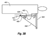
図1及び図2に示す方式により構成されたX線管の使用により達成される結果の利点を描写する簡略図の図3A及び3Bを次に参照する。特に、図3A及び図3Bは、X線管により撮影される胸部402等の撮影対象を有する患者400を示す。要するに、図3Aは、一般的なX線管のアノードのみを示し、一方、図3Bは、上記に既に説明した方式による縮小された距離ΔHを有する図1及び図2に示すように構成されたX線管10のアノード104のみを示す。説明すると、図に描写された撮影対象は、マンモグラフィー工程の一部として撮影された胸部であるが、患者の他の部分も代替的に撮影可能である。
Reference is now made to FIGS. 3A and 3B, which are simplified diagrams depicting the benefits of results achieved by use of an x-ray tube constructed in the manner shown in FIGS. In particular, FIGS. 3A and 3B show a
マンモグラフィー工程において、X線は、図3Bのアノード104の焦点位置114のようなアノードの焦点位置にて生成される。X線管は、406にて示された中心線が患者400の胸壁408と実質的に並行となるように配置される。撮影フィルム又はフラットパネル撮影機404は、胸部の遠い側に配置される。一般的な構成について説明すると、胸部は圧縮され、フラットパネルは、焦点位置に対して反対側にて圧縮された胸部に近接して配置される。図3A及び図3Bのファン64Aにより描写されるように、コーン形状パターンのX線は扇状に広がる。検出パネル404は、X線コーン64AのX線が胸部402を通過した結果として生成される映像を取り込むように配置される。検出部404は、X線フィルムの形式であるか、又はフラットパネル撮影機として動作可能である。
In the mammography process, x-rays are generated at the focal position of the anode, such as the
中心線406は、図3A及び図3Bの各X線コーン64Aにより画定される。患者400の胸壁408に向かって中心線406から拡大するX線コーン64Aの位置は、“ρ”により示され、一方、胸壁から離れて中心線から拡大するX線コーン部分は、“θ”により示される。ヒール効果では、アノードの外周に比較的近い焦点位置の領域に電子が衝突して生成されるX線を構成するX線コーンの部分は、他のコーン部分より相対的に密度が小さく、ヒール効果は、図3Aにより示される一般的なX線コーンのθ部分により示される。
反対に、ヒール効果は、図3Bにより示される、現状のX線管構成の改良されたアノード104にて生成されたX線コーン64Aのρ部分により理解される。本実施形態、即ち、アノードと真空筐体の第1端壁との間からのカソードアセンブリの除去に基づくX線管の構成の結果として患者400の胸壁408に対して比較的近くに、アノード及びアノードに対応する焦点位置114が配置されるため、ヒール効果の問題が低減する。
Conversely, the heel effect is understood by the ρ portion of the
図3Bの構成は、同様に他の点においても有効である。例えば、図3Aの構成から理解し得るように、胸部全体は放射されず、特に解像度及び撮影に重要な胸壁の範囲は放射されない。補償するためには、焦点軌道112の角度がターゲット表面110(図2)の残りに対応して増加すること、及びX線管が胸部全体及び撮影機に照射するように傾斜することの少なくとも一方を行わなければならない。しかしながら、管の傾斜角度の増加と同様に、焦点軌道112の角度が増加すると、装置の焦点位置の距離を増加させ、画像品質が低下する。直接対比すると、図3Bの動作において、距離ΔHの縮小は、焦点軌道の角度又は管傾斜の増加を必要とせずに、より大きな胸部及び撮影機の部分に対して放射可能となる。このことは、装置の焦点位置の距離をより短く維持することができ、それにより、画像品質が向上する結果となる。
The configuration of FIG. 3B is also effective in other respects as well. For example, as can be seen from the configuration of FIG. 3A, the entire chest is not radiated, particularly the area of the chest wall that is important for resolution and imaging. To compensate, at least one of the angle of the
ΔHの縮小は、同様に他の点において有効である。例えば、焦点位置から管の端部の距離が縮小するため、適切な撮影を確実にするために管を患者の近くに配置する必要がなく、患者の快適さが向上する。このことは、管が患者の頭部及び胸部の反対側の撮影機(例えば、図3A及び図3Bにおいてアノード104及び撮影機404の相対位置が反対となる)に隣接して配置されるマンモグラフィー工程において重要である。さらに、マンモ・CT(胸部撮影のためのコンピュータ断層撮影)システムにおいて、管及びデジタル撮影機は、示された方式にて体の下側を通過し、このような構成は、胸壁の範囲を適切に撮影することを確実にするアプリケーション環境において特に重要である。
The reduction of ΔH is effective in other points as well. For example, the distance from the focal point to the end of the tube is reduced, so that it is not necessary to place the tube close to the patient to ensure proper imaging, improving patient comfort. This means that the tube is positioned adjacent to the radiographer opposite the patient's head and chest (eg, the relative positions of the
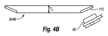
本発明の他の例示的な実施形態に基づく、種々の可能なアノード構成を描写する図4A〜図4Dを参照する。図4Aは、厚さT1、及び上記のような図1及び図2に示されるアノード104と同様な構成を有するアノード304Aを示す。アノード304Aは、図4B〜図4Dに示される他のアノード構成と同様に、図4Aに示された方向に基づいて下側に面する焦点軌道112と、既に説明された、焦点軌道に対応して配置されるカソードアセンブリのカソードヘッド56とを含む。
Reference is made to FIGS. 4A-4D depicting various possible anode configurations, according to other exemplary embodiments of the present invention. FIG. 4A shows an
図4Bは、他の実施形態に基づくアノード304Bを描写し、アノードは、比較的薄く形成され、図4Aに示すアノード304Aの厚さT1より薄い厚さT2を有する。このことは、焦点位置と真空筐体の最も近い端部との間の距離ΔH(図2)を縮小する。
FIG. 4B depicts an
図4Cは、比較的厚いアノード304Cを示し、アノード304Cは、管動作中に熱除去のために増加した体積を有する。厚さT3を有する肉厚のアノード304Cのバルクは、真空筐体の端部に対する焦点位置の相対的な近接を維持するように、焦点軌道112の内周内側の放射状の位置に含まれる。
FIG. 4C shows a relatively
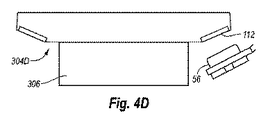
図4Dは、アノード304Dを示し、アノード304Dは、アノード304Dに結合されたグラファイト(又は同様な物質)部分306を有し、管動作中に焦点軌道から熱除去することを支援する。また、グラファイト部分306は、真空筐体の端部に対する焦点位置の相対的な近接(図2のΔHを参照)を維持するように、焦点軌道112の内周半形方向内側に配置される。グラファイトをこのようにターゲットの反対側に移動することは、焦点位置と真空筐体の最も近い端部との間の距離ΔHを縮小する他の方式である。
FIG. 4D shows an anode 304D, which has a graphite (or similar material)
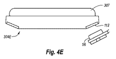
図4Eは、使用される他の潜在的なアノード装置304Eを示す。この特有な実施形態では、グラファイト部分は、カソード56からアノード構造304Eの反対側に配置される。また、グラファイト307(又は同様な物質)は、動作中に焦点軌道から熱除去することを支援する。グラファイトの厚さは、最小にすることができ、所定のアプリケーションの必要性に応じてΔHの縮小を達成する。図4A〜図4Dに描写されるアノード構成は、種々の方式の例示であり、本発明の実施形態の原理を種々のX線管構成に組み込むことが可能である。他の構成及び手法が使用されることは理解できる。
FIG. 4E shows another
例示的な一実施形態では、X線管10(図1,2)は、接地したアノード構成を含むことができ、アノード104は、電気的に接地され、カソードアセンブリ50は、アノードに対して高電位に保持される。この構成は、真空筐体の第1端壁140に対するアノード104の間隔の必要条件である電圧隔離絶縁を縮小し、それにより、アノードと第1端壁との間の間隔を縮小することができる。また、カソードアセンブリ50が高電圧を維持することは、セラミックフィードスルー58等の適切な絶縁構造を用いて可能となり、カソードアセンブリ50の部分が真空筐体の側壁144より延出可能となる。
In one exemplary embodiment, x-ray tube 10 (FIGS. 1 and 2) can include a grounded anode configuration,
本発明の実施形態の実行により、X線管のアノードの焦点位置と、アノードが配置された真空筐体の隣接した端壁との間の間隔が縮小することが提供される。このことは、同様に、X線管が撮影対象に対して相対的に近くに配置され、多くの利点を提供する。本発明に使用される一実施形態により、マンモグラフィー工程における特有の適応性が理解され、公知のX線管の構成より患者の胸壁に対して相対的に近くに配置可能となる。結果として、改良された胸部組織の撮影は実現する。 Implementation of embodiments of the present invention provides for a reduction in the spacing between the focal position of the anode of the x-ray tube and the adjacent end wall of the vacuum housing in which the anode is located. This likewise provides a number of advantages when the X-ray tube is placed relatively close to the object being imaged. One embodiment used in the present invention understands the unique applicability of the mammography process and allows it to be positioned relatively closer to the patient's chest wall than known x-ray tube configurations. As a result, improved chest tissue imaging is achieved.
さらに、例示的な実施形態では、焦点位置と筐体の端壁との間隔をさらに縮小するように利用可能である。さらにまた、アノードの焦点軌道の角度は減少され、それにより、焦点位置の全体サイズが望ましくは縮小する。 Furthermore, in the exemplary embodiment, the distance between the focal position and the end wall of the housing can be used to further reduce the distance. Furthermore, the angle of the anode focal trajectory is reduced, thereby desirably reducing the overall size of the focal position.
本発明は、その技術思想および基本的特徴から逸脱しない範囲で、他の特定の形態でも実現することができる。上記した実施形態は、全ての面で単に例示的なものであり、限定的なものではない。本発明の範囲はしたがって、前述の記載によってではなく、特許請求の範囲によって示される。特許請求の範囲の同等物の意味および範囲内にある全ての変形が、その範囲内に含まれる。 The present invention can be implemented in other specific forms without departing from the technical idea and basic features thereof. The above-described embodiments are merely illustrative in all aspects and are not limiting. The scope of the invention is, therefore, indicated by the appended claims rather than by the foregoing description. All variations that come within the meaning and range of equivalency of the claims are to be embraced within their scope.
Claims (20)
第1端部を有する真空筐体と、
軸受けアセンブリと、
前記真空筐体内の前記軸受けアセンブリにより支持される回転式アノードであって、
前記アノードは、マンモグラフィー工程において患者の胸壁とほぼ平行に配置されるように構成され、
前記アノードは、
前記軸受けアセンブリに対向するターゲット表面と、
前記真空筐体の第1端部に対向する反対側の第2表面と
を含む、前記アノードと、
電子を放射して前記ターゲット表面の一部に衝突するように配置されるカソードと、
マンモグラフィー工程において患者の胸壁に近接して配置されるように構成される第1端部を有する外側ハウジングとを備え、
前記真空筐体は、前記真空筐体の前記第1端部が前記外側ハウジングの第1端部に近接して配置されるように、前記外側ハウジング内に配置される、X線管。 An x-ray tube for the mammography process ,
A vacuum housing having a first end;
A bearing assembly;
A rotary anode supported by the bearing assembly in the vacuum housing;
The anode is configured to be disposed substantially parallel to a patient's chest wall in a mammography process;
The anode is
A target surface facing the bearing assembly;
And a opposite second surface opposite the first end portion of said vacuum enclosure, and the anode,
A cathode disposed to emit electrons and strike a portion of the target surface;
An outer housing having a first end configured to be positioned proximate to a patient's chest wall in a mammography process ;
The vacuum housing is disposed within the outer housing such that the first end of the vacuum housing is disposed proximate to the first end of the outer housing .
前記カソードは、前記側壁の一部を介して延出する、請求項1に記載のX線管。 The vacuum housing includes side walls that interconnect the first end and the second end;
The X-ray tube according to claim 1, wherein the cathode extends through a part of the side wall.
前記窓は、前記真空筐体の前記第1端部と近接して配置される、請求項2に記載のX線管。 Including a window formed in the side wall of the vacuum housing;
The X-ray tube according to claim 2, wherein the window is disposed in proximity to the first end portion of the vacuum casing.
前記カソードは、電子を放射して前記焦点軌道の焦点位置上に衝突するように配置されるフィラメントを有する、請求項1に記載のX線管。 The anode has a focal trajectory defined on a frustoconical portion of the target surface of the anode;
The X-ray tube according to claim 1, wherein the cathode has a filament arranged to emit electrons and collide with the focal position of the focal track.
前記カソードは、前記軸受けアセンブリの側方に配置される、請求項7に記載のX線管。 The filament of the cathode is included in a cathode head;
The x-ray tube as recited in claim 7 , wherein the cathode is disposed laterally of the bearing assembly.
第1端部を有する真空筐体であって、
軸受けアセンブリ及びステムを有するローターアセンブリと、
前記ローターアセンブリの前記ステムにより支持される回転式アノードであって、
前記アノードは、マンモグラフィー工程において患者の胸壁とほぼ平行に配置されるように構成され、
前記アノードは、
角度付けされた焦点軌道を含むターゲット表面であって、前記軸受けアセンブリに対向するように配置される前記ターゲット表面と、
前記真空筐体の前記第1端部と対向するように配置される第2表面であって、前記第2表面と前記真空筐体の前記第1端部との間に介在構造が実質的に配置されない、前記第2表面と
を含む、前記アノードと、
カソードヘッドを含むカソードアセンブリであって、前記カソードヘッドは、該カソードヘッド中に配置されるフィラメントを有し、前記フィラメントは、前記フィラメントから放射される電子が前記アノードの焦点軌道の焦点位置に衝突するように配向される、前記カソードアセンブリと
を含む、前記真空筐体と、
マンモグラフィー工程において患者の胸壁に近接して配置されるように構成される第1端部を有する外側ハウジングとを備え、
前記真空筐体は、前記真空筐体の前記第1端部が前記外側ハウジングの第1端部に近接して配置されるように、前記外側ハウジング内に配置される、マンモグラフィー工程に用いるためのX線管。 An x-ray tube for use in a mammography process,
A vacuum enclosure having a first end,
A rotor assembly having a bearing assembly and a stem;
A rotating anode supported by the stem of the rotor assembly;
The anode is configured to be disposed substantially parallel to a patient's chest wall in a mammography process;
The anode is
A target surface comprising an angled focal track, wherein the target surface is positioned to face the bearing assembly;
A second surface disposed to face the first end of the vacuum casing, wherein an interposition structure is substantially provided between the second surface and the first end of the vacuum casing. The anode comprising the second surface not disposed; and
A cathode assembly including a cathode head, the cathode head having a filament disposed in the cathode head, wherein the filament collides with a focal position of a focal path of the anode by electrons emitted from the filament. The vacuum housing including the cathode assembly, oriented to
An outer housing having a first end configured to be positioned proximate to a patient's chest wall in a mammography process ;
The vacuum housing is disposed in the outer housing such that the first end of the vacuum housing is disposed in proximity to the first end of the outer housing for use in a mammography process. X-ray tube.
絶縁構造を介して、前記真空筐体の円柱形状の側壁を通過する、請求項15に記載のマンモグラフィー工程に用いるためのX線管。 A portion of the cathode assembly is
The X-ray tube for use in the mammography process according to claim 15 , which passes through a cylindrical side wall of the vacuum casing through an insulating structure.
前記カソードアセンブリは所定の電位に維持される、請求項16に記載のマンモグラフィー工程に用いるためのX線管。 The anode is grounded;
The x-ray tube for use in a mammography process according to claim 16 , wherein the cathode assembly is maintained at a predetermined potential.
Applications Claiming Priority (3)
| Application Number | Priority Date | Filing Date | Title |
|---|---|---|---|
| US11/944,188 US8284899B2 (en) | 2007-11-21 | 2007-11-21 | X-ray tube having a focal spot proximate the tube end |
| US11/944,188 | 2007-11-21 | ||
| PCT/US2008/084234 WO2009067623A1 (en) | 2007-11-21 | 2008-11-20 | X-ray tube having a focal spot proximate the tube end |
Publications (2)
| Publication Number | Publication Date |
|---|---|
| JP2011504647A JP2011504647A (en) | 2011-02-10 |
| JP5437262B2 true JP5437262B2 (en) | 2014-03-12 |
Family
ID=40641958
Family Applications (1)
| Application Number | Title | Priority Date | Filing Date |
|---|---|---|---|
| JP2010535074A Active JP5437262B2 (en) | 2007-11-21 | 2008-11-20 | X-ray tube having a focal position close to the tube end |
Country Status (4)
| Country | Link |
|---|---|
| US (1) | US8284899B2 (en) |
| EP (1) | EP2219524B1 (en) |
| JP (1) | JP5437262B2 (en) |
| WO (1) | WO2009067623A1 (en) |
Families Citing this family (3)
| Publication number | Priority date | Publication date | Assignee | Title |
|---|---|---|---|---|
| US8867706B2 (en) * | 2010-11-09 | 2014-10-21 | Varian Medical Systems, Inc. | Asymmetric x-ray tube |
| JP6304986B2 (en) * | 2013-09-19 | 2018-04-04 | キヤノン株式会社 | Breast tomography equipment |
| JP6304985B2 (en) | 2013-09-19 | 2018-04-04 | キヤノン株式会社 | Radiography equipment |
Family Cites Families (24)
| Publication number | Priority date | Publication date | Assignee | Title |
|---|---|---|---|---|
| JPS491589Y1 (en) * | 1970-12-14 | 1974-01-16 | ||
| FR2235478B1 (en) | 1973-06-29 | 1977-02-18 | Radiologie Cie Gle | |
| JPS5035172U (en) | 1973-07-25 | 1975-04-14 | ||
| AT346981B (en) * | 1976-03-18 | 1978-12-11 | Plansee Metallwerk | ROTARY ROTARY ANODE AND METHOD FOR MANUFACTURING IT |
| JPS5924487B2 (en) * | 1977-02-07 | 1984-06-09 | 株式会社東芝 | x-ray tube |
| US4336476A (en) * | 1978-09-05 | 1982-06-22 | The Machlett Laboratories, Incorporated | Grooved X-ray generator |
| US4884292A (en) * | 1981-12-02 | 1989-11-28 | Medical Electronic Imaging Corporation | Air-cooled X-ray tube |
| FR2545649B1 (en) * | 1983-05-06 | 1985-12-13 | Thomson Csf | RADIOGENIC TUBE WITH ROTATING ANODE |
| DE3341976A1 (en) * | 1983-11-21 | 1985-05-30 | Siemens AG, 1000 Berlin und 8000 München | X-ray diagnosis apparatus |
| FR2623331A1 (en) * | 1987-11-13 | 1989-05-19 | Thomson Cgr | X-RAY TUBE HAVING A MOLYBDENE TARGET |
| JPH01204649A (en) * | 1988-02-12 | 1989-08-17 | Toshiba Corp | X-ray photographing device |
| JP2886577B2 (en) * | 1989-11-15 | 1999-04-26 | 寛 磯部 | Flash X-ray tube with rotating anode |
| JP2726252B2 (en) * | 1995-02-28 | 1998-03-11 | ゼネラル・エレクトリック・カンパニイ | X-ray tube |
| US5978447A (en) * | 1997-11-11 | 1999-11-02 | Picker International, Inc. | X-ray tube straddle bearing assembly |
| US6662042B1 (en) | 2000-08-22 | 2003-12-09 | Richard J. Grable | Diagnostic tomographic laser imaging apparatus |
| US6987831B2 (en) | 1999-11-18 | 2006-01-17 | University Of Rochester | Apparatus and method for cone beam volume computed tomography breast imaging |
| US6430260B1 (en) * | 2000-12-29 | 2002-08-06 | General Electric Company | X-ray tube anode cooling device and systems incorporating same |
| US6707882B2 (en) | 2001-11-14 | 2004-03-16 | Koninklijke Philips Electronics, N.V. | X-ray tube heat barrier |
| US7108421B2 (en) | 2002-03-19 | 2006-09-19 | Breakaway Imaging, Llc | Systems and methods for imaging large field-of-view objects |
| US6816574B2 (en) * | 2002-08-06 | 2004-11-09 | Varian Medical Systems, Inc. | X-ray tube high voltage connector |
| AU2003268462A1 (en) * | 2002-09-03 | 2004-03-29 | Parker Medical, Inc. | Multiple grooved x-ray generator |
| US6983035B2 (en) * | 2003-09-24 | 2006-01-03 | Ge Medical Systems Global Technology Company, Llc | Extended multi-spot computed tomography x-ray source |
| US7203281B2 (en) * | 2004-03-11 | 2007-04-10 | Varian Medical Systems, Inc. | Encapsulated stator assembly for an x-ray tube |
| FR2875693B1 (en) | 2004-09-24 | 2006-12-08 | Gen Electric | X-RAY TOMOGRAPHY DEVICE |
-
2007
- 2007-11-21 US US11/944,188 patent/US8284899B2/en active Active
-
2008
- 2008-11-20 EP EP08852149.7A patent/EP2219524B1/en active Active
- 2008-11-20 WO PCT/US2008/084234 patent/WO2009067623A1/en not_active Ceased
- 2008-11-20 JP JP2010535074A patent/JP5437262B2/en active Active
Also Published As
| Publication number | Publication date |
|---|---|
| JP2011504647A (en) | 2011-02-10 |
| US20090129549A1 (en) | 2009-05-21 |
| EP2219524B1 (en) | 2016-03-16 |
| EP2219524A1 (en) | 2010-08-25 |
| US8284899B2 (en) | 2012-10-09 |
| WO2009067623A1 (en) | 2009-05-28 |
| EP2219524A4 (en) | 2011-10-05 |
Similar Documents
| Publication | Publication Date | Title |
|---|---|---|
| US6361208B1 (en) | Mammography x-ray tube having an integral housing assembly | |
| CN102142346B (en) | X-ray cathode and method of manufacture the same | |
| JP4644187B2 (en) | X-ray tube with internal radiation shield | |
| US9514911B2 (en) | X-ray tube aperture body with shielded vacuum wall | |
| US9530528B2 (en) | X-ray tube aperture having expansion joints | |
| CN102099888A (en) | X-ray sources and X-ray apparatus incorporating such X-ray sources | |
| US6907110B2 (en) | X-ray tube with ring anode, and system employing same | |
| US20170250051A1 (en) | Robust Electrode With Septum Rod For Biased X-Ray Tube Cathode | |
| CN119581297A (en) | X-ray tube anode with optimized focal spot trajectory | |
| JP5437262B2 (en) | X-ray tube having a focal position close to the tube end | |
| US7643614B2 (en) | Method and apparatus for increasing heat radiation from an x-ray tube target shaft | |
| JP2010262784A (en) | X-ray tube and X-ray tube device | |
| US7852987B2 (en) | X-ray tube having a rotating and linearly translating anode | |
| US12520410B2 (en) | X-ray tube assembly and X-ray CT equipment | |
| US7058160B2 (en) | Shield structure for x-ray device | |
| US9202664B2 (en) | Finned anode | |
| JP3030069B2 (en) | X-ray tube | |
| US7145988B2 (en) | Sealed electron beam source | |
| CN116564776B (en) | An X-ray tube and CT equipment | |
| JP5865249B2 (en) | X-ray tube apparatus, manufacturing method thereof, and X-ray diagnostic imaging apparatus | |
| CN113421810A (en) | Full-angle arc-shaped array X-ray tube and annular ray device | |
| JPWO2014171234A1 (en) | X-ray tube apparatus and X-ray imaging apparatus |
Legal Events
| Date | Code | Title | Description |
|---|---|---|---|
| RD04 | Notification of resignation of power of attorney |
Free format text: JAPANESE INTERMEDIATE CODE: A7424 Effective date: 20120120 |
|
| A977 | Report on retrieval |
Free format text: JAPANESE INTERMEDIATE CODE: A971007 Effective date: 20120803 |
|
| A131 | Notification of reasons for refusal |
Free format text: JAPANESE INTERMEDIATE CODE: A131 Effective date: 20120807 |
|
| A601 | Written request for extension of time |
Free format text: JAPANESE INTERMEDIATE CODE: A601 Effective date: 20121105 |
|
| A602 | Written permission of extension of time |
Free format text: JAPANESE INTERMEDIATE CODE: A602 Effective date: 20121112 |
|
| A601 | Written request for extension of time |
Free format text: JAPANESE INTERMEDIATE CODE: A601 Effective date: 20121207 |
|
| A602 | Written permission of extension of time |
Free format text: JAPANESE INTERMEDIATE CODE: A602 Effective date: 20121214 |
|
| A521 | Request for written amendment filed |
Free format text: JAPANESE INTERMEDIATE CODE: A523 Effective date: 20130206 |
|
| TRDD | Decision of grant or rejection written | ||
| A01 | Written decision to grant a patent or to grant a registration (utility model) |
Free format text: JAPANESE INTERMEDIATE CODE: A01 Effective date: 20131112 |
|
| A61 | First payment of annual fees (during grant procedure) |
Free format text: JAPANESE INTERMEDIATE CODE: A61 Effective date: 20131211 |
|
| R150 | Certificate of patent or registration of utility model |
Ref document number: 5437262 Country of ref document: JP Free format text: JAPANESE INTERMEDIATE CODE: R150 Free format text: JAPANESE INTERMEDIATE CODE: R150 |
|
| R250 | Receipt of annual fees |
Free format text: JAPANESE INTERMEDIATE CODE: R250 |
|
| R250 | Receipt of annual fees |
Free format text: JAPANESE INTERMEDIATE CODE: R250 |
|
| S111 | Request for change of ownership or part of ownership |
Free format text: JAPANESE INTERMEDIATE CODE: R313113 |
|
| R350 | Written notification of registration of transfer |
Free format text: JAPANESE INTERMEDIATE CODE: R350 |
|
| R250 | Receipt of annual fees |
Free format text: JAPANESE INTERMEDIATE CODE: R250 |
|
| R250 | Receipt of annual fees |
Free format text: JAPANESE INTERMEDIATE CODE: R250 |
|
| R250 | Receipt of annual fees |
Free format text: JAPANESE INTERMEDIATE CODE: R250 |
|
| R250 | Receipt of annual fees |
Free format text: JAPANESE INTERMEDIATE CODE: R250 |
|
| R250 | Receipt of annual fees |
Free format text: JAPANESE INTERMEDIATE CODE: R250 |
|
| R250 | Receipt of annual fees |
Free format text: JAPANESE INTERMEDIATE CODE: R250 |
|
| R250 | Receipt of annual fees |
Free format text: JAPANESE INTERMEDIATE CODE: R250 |