JP4758058B2 - Extended stereophonic circuit with tone compensation - Google Patents
Extended stereophonic circuit with tone compensation Download PDFInfo
- Publication number
- JP4758058B2 JP4758058B2 JP2003135123A JP2003135123A JP4758058B2 JP 4758058 B2 JP4758058 B2 JP 4758058B2 JP 2003135123 A JP2003135123 A JP 2003135123A JP 2003135123 A JP2003135123 A JP 2003135123A JP 4758058 B2 JP4758058 B2 JP 4758058B2
- Authority
- JP
- Japan
- Prior art keywords
- signal
- frequency
- extension
- inverting input
- input terminal
- Prior art date
- Legal status (The legal status is an assumption and is not a legal conclusion. Google has not performed a legal analysis and makes no representation as to the accuracy of the status listed.)
- Expired - Fee Related
Links
- 238000006880 cross-coupling reaction Methods 0.000 claims description 9
- 230000001419 dependent effect Effects 0.000 claims 2
- 238000001914 filtration Methods 0.000 claims 2
- 239000003990 capacitor Substances 0.000 description 23
- 230000008878 coupling Effects 0.000 description 6
- 238000010168 coupling process Methods 0.000 description 6
- 238000005859 coupling reaction Methods 0.000 description 6
- 230000000694 effects Effects 0.000 description 5
- 238000000926 separation method Methods 0.000 description 3
- 238000010586 diagram Methods 0.000 description 2
- 210000005069 ears Anatomy 0.000 description 2
- 230000007704 transition Effects 0.000 description 2
- 230000007423 decrease Effects 0.000 description 1
- WABPQHHGFIMREM-UHFFFAOYSA-N lead(0) Chemical compound [Pb] WABPQHHGFIMREM-UHFFFAOYSA-N 0.000 description 1
- 238000000034 method Methods 0.000 description 1
Images

Classifications
-
- H—ELECTRICITY
- H04—ELECTRIC COMMUNICATION TECHNIQUE
- H04S—STEREOPHONIC SYSTEMS
- H04S1/00—Two-channel systems
- H04S1/002—Non-adaptive circuits, e.g. manually adjustable or static, for enhancing the sound image or the spatial distribution
-
- H—ELECTRICITY
- H04—ELECTRIC COMMUNICATION TECHNIQUE
- H04S—STEREOPHONIC SYSTEMS
- H04S3/00—Systems employing more than two channels, e.g. quadraphonic
-
- H—ELECTRICITY
- H04—ELECTRIC COMMUNICATION TECHNIQUE
- H04R—LOUDSPEAKERS, MICROPHONES, GRAMOPHONE PICK-UPS OR LIKE ACOUSTIC ELECTROMECHANICAL TRANSDUCERS; DEAF-AID SETS; PUBLIC ADDRESS SYSTEMS
- H04R5/00—Stereophonic arrangements
- H04R5/04—Circuit arrangements, e.g. for selective connection of amplifier inputs/outputs to loudspeakers, for loudspeaker detection, or for adaptation of settings to personal preferences or hearing impairments
Landscapes
- Physics & Mathematics (AREA)
- Engineering & Computer Science (AREA)
- Acoustics & Sound (AREA)
- Signal Processing (AREA)
- Stereophonic System (AREA)
- Stereo-Broadcasting Methods (AREA)
Description
【0001】
【発明の属する技術分野】
本発明は、立体音響信号を含んだテレビ番組信号を受信するためのテレビジョン受信機に関し、より詳細には、複数の拡声器が実際の物理的分離以上に空間的に分離しているように音響的に聴取音が感じるような、音調補償された心理音響立体音響拡張効果の生成に関する。
【0002】
【従来の技術】
音響再生装置およびテレビジョン受信機における空間立体拡張については良く知られており、永年に渡って利用されている。このようなシステムでは、左右のチャネル信号は、間隔を隔てた拡声器からの左右のチャネル信号が、拡声器の実際の物理的分離以上に距離を隔てて聴取者に出現するような方法で処理され、心理音響拡張と呼ばれている。いくつかの空間立体拡張の実施例が示されている(例えば、特許文献1、2および3参照)。このような空間拡張系では、広々とした空間環境が左右のチャネルの間に導入されるよう、もう一方のチャネルからの反転信号の一部が、当該チャネルの信号に付加されている。この特徴は、音響知覚立体イメージを1対の立体音響拡声器の実際の位置より幅を広げて出現させる場合に有利な特性を有している。この特徴は、拡声器と拡声器の間の間隔が、通常、約26〜80cm程度しか離れていないテレビジョン受信機あるいは小型ラジオの場合に特に有利である。
【0003】
最も有効な立体拡張スキームでは、中間レンジの周波数の半波長が人間の両耳の間の間隔とほぼ同じ長さであるため、差信号の中間レンジの周波数をブーストしている。聴取者の左側または右側から発せられる音は、その音が適切な(中間レンジの)周波数の音である場合、両耳の間で位相が相殺される。これは、音をその発生位置から受け取るための主要な方向決定糸口の1つである。
【0004】
【特許文献1】
米国特許第5,208,493号明細書
【0005】
【特許文献2】
米国特許第4,831,652号明細書
【0006】
【特許文献3】
米国特許第4,495,637号明細書
【0007】
【発明が解決しようとする課題】
拡張立体系は、基本的には同じことを実行し、例えばL立体チャネルとR立体チャネルの差(L−R)を、それらの和信号(L+R)に相関して増幅しているが、このような拡張により、一般的に和信号である音声が「追い出され」、明瞭性に欠ける会話になっている。また、拡張系は、差信号の中間周波数帯域を、低可聴周波数および高可聴周波数に相関して増幅しており、そのために中間レンジの音色が音に付加されている。
【0008】
【課題を解決するための手段】
L信号チャネルおよびR信号チャネルのための立体音響拡張回路であって、L信号チャネルおよびR信号チャネルの各々は、それぞれ非反転および反転入力端子および出力端子を有する第1および第2の増幅器を備えている。信号は、各非反転入力端子に結合され、また、各出力端子と各反転入力端子の間に第1の帰還経路が結合されている。フィルタが反転入力端子を1つに結合し、心理音響拡張効果を提供している。入力端子と出力端子の間に結合された受動周波数補償回路が、拡張信号に対する音調補償を提供している。
【0009】
【発明の実施の形態】
図1は、従来技術による例示的立体拡張回路を示したもので、立体拡張回路10は、2つの演算増幅器(オペアンプ)11および12を備えている。左(L)チャネル信号は、入力ライン14によってオペアンプ11の正(非反転)入力端子13に印加され、右(R)チャネル信号は、入力ライン16によってオペアンプ12の負(非反転)入力端子15に印加されている。出力ライン17および20の右チャネル出力信号および左チャネル出力信号は、それぞれ抵抗22および24によって、それぞれ反転入力部26および28に帰還されている。反転入力部26および28の信号の一部は、フィルタ30を介して互いに交差結合されている。
【0010】
交差結合信号は、各チャネルの出力を他のチャネルの出力に影響を及ぼしている。詳細には、交差結合により、オペアンプ11の左出力ライン17上の出力信号がL+X(L−R)信号になり、一方、オペアンプ12の右出力ライン20上の出力信号がR+X(R−L)信号になる。交差結合係数「X」は、フィルタ30の特性によって決まる値である。この回路の利得は周波数によって決まり、その範囲は、0.5と2.0の間であることがしばしばである。
【0011】
フィルタ30は、コンデンサ32および抵抗34を備えている。コンデンサ32および抵抗34の値は、所望する交差結合の量および交差結合の交差周波数によって決まる。結合係数Xが大きくなると、拡声器の見掛け上の分離が増加する。抵抗34の値が大きくなると、それぞれ反転入力部26および28に結合されている帰還素子に流れ込む信号電流が小さくなるため、交差結合が小さくなる。コンデンサ32は、抵抗34と共に交差結合の交差周波数を決定している。通常、コンデンサ32の値は、低周波数では結合が小さく、信号周波数が約150Hzまたは200Hzに増加すると交差結合が開始され、約1KHzないし3KHzで全結合が達成されるように選択されている。
【0012】
帰還抵抗22および24にそれぞれ並列に接続されている帰還コンデンサ36および38は、増幅器11および12の各々の周波数応答をロールオフさせ、それによりフィルタ30を介したチャネル間の5KHz以上の交差結合を小さくしている。各例示的チャネルの上側周波数ブレークポイントは、Fu=1/(2π(コンデンサ36/38)(抵抗22/24))であり、下側周波数ブレークポイントは、Fl=1/(2π(コンデンサ32)(抵抗34))である。これらのブレークポイントの効果により、中間周波数音調ブーストが提供されている。
【0013】
図2に使用されている数表示は、図1に関連して上で考察した部材の数表示と同じであり、簡潔性を期すため、既に考察した部材については、図2では省略する。
【0014】
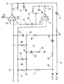
信号入力リード線14、16の各々は、例えばユニティフィードバック(unity feedback)のオペアンプなどの低インピーダンス信号源(図示せず)に、信号源のインピーダンスが基本的にゼロオームになるように結合されている。抵抗42およびコンデンサ44からなる並列RC回路網40は、左入力リード線16に接続され、同様に、抵抗48およびコンデンサ50からなる並列RC回路網46は、右信号入力リード線14に接続されている。回路網40および46は、入力信号の加算ジャンクションすなわちL+Rを形成しているノード52に接続されている。コンデンサ56および抵抗58からなる直列RC回路網54は、ノード52を接地に接続している。L拡張信号出力端子17およびR拡張信号出力端子20は、それぞれ抵抗60および62に結合されている。抵抗60および62は、それぞれ拡張信号出力ノード64および66に結合され、拡張信号出力ノード64および66は、それぞれ抵抗68および70を介して加算ノード52に結合されている。
【0015】
回路網40および46は高域通過フィルタであり、その遷移周波数すなわちコンデンサのインピーダンスと抵抗のレジスタンスが等しくなる信号周波数は、3,600Hzである。回路網54は低域通過フィルタであり、その遷移周波数は340Hzである。したがってノード52における和信号L+Rは、中間レンジの信号周波数に対してブーストされた低音部、およびブーストされた高音部を有している。オペアンプ11および12は、それぞれ抵抗22および24によって提供される帰還量が多いため、その出力インピーダンスが極めて小さく、そのために次にこの音調補償信号が、それぞれ抵抗ドライバ70、62および68、60によって、ノード66およびノード64の左右の両出力信号に付加される。この方法によれば、高音部および低音部がブーストされた音調補償和信号が、既に中間レンジがブーストされている立体拡張信号に付加され、それにより、さもなければサラウンド音響システム、例えばDolby(商標)5.1の中央拡声器に導かれることになる会話または他の中央発信信号の明瞭性がさらに向上する。
【0016】
結合回路をベースとする場合、様々な抵抗およびコンデンサが互いに相互作用することに言及しておく。系の低周波数ブレークポイントが約115Hzの場合、系の低周波数ブレークポイントは、主としてコンデンサ56および抵抗42、48および58の並列結合によって決まり、コンデンサ44および50の効果は二次的なものである。高周波数ブレークポイントが約5KHzの場合、系の高周波数ブレークポイントは、主として、抵抗58に直列に結合された抵抗42および48にそれぞれ並列に接続されたコンデンサ44および50の並列結合によって決まり、コンデンサ56の効果は二次的なものである。
【0017】
例示的実施形態では、各構成素子の値はそれぞれ、抵抗22、24、42および48が20K、抵抗60および62が30K、抵抗68および70が47K、抵抗34および58が10K、コンデンサ44および50が2.2nf(ナノファラド)、コンデンサ56が100nf、コンデンサ36および38が4.7nf、およびコンデンサ32が100nfである。コンデンサ72および74は結合コンデンサであり、その値は1μf(マイクロファラド)である。
【0018】
この音調補償は、空間的に拡張する2つのチャネルに関して考察されているが、この音調補償は、例えばサラウンド音響再生装置などの3チャネル以上の系に適用することも可能である。サラウンド音響再生装置では、例えば(L−R)、(R−L)信号などの差音が後部拡声器に供給される。この音調補償は、後部拡声器信号が空間的に拡張するかどうかに無関係に、あるいは後部拡声器信号の中間レンジが空間的に拡張するかどうかに無関係に適用することができる。
【図面の簡単な説明】
【図1】従来技術による立体音響拡張回路を示す図である。
【図2】本発明の態様による音調補償付き立体音響拡張回路を示す図である。
【符号の説明】
10 従来技術による立体拡張回路
11、12 演算増幅器(オペアンプ)
13 オペアンプ11の正(非反転)入力端子
14、16 入力ライン(入力リード線)
15 オペアンプ12の正(非反転)入力端子
17、20 出力ライン(拡張信号出力端子)
22、24、34、42、48、58、60、62、68、70 抵抗
26、28 反転入力部
30 フィルタ
32、36、38、44、50、56 コンデンサ
40、46 並列RC回路網
52、64、66 ノード
54 直列RC回路網
72、74 結合コンデンサ[0001]
BACKGROUND OF THE INVENTION
The present invention relates to a television receiver for receiving a television program signal including a stereophonic signal, and more particularly, such that a plurality of loudspeakers are separated spatially beyond actual physical separation. The present invention relates to the generation of a tone-compensated psychoacoustic stereophonic expansion effect that makes it possible to feel the listening sound acoustically.
[0002]
[Prior art]
Spatial spatial expansion in sound reproduction devices and television receivers is well known and has been used for many years. In such a system, the left and right channel signals are processed in such a way that the left and right channel signals from spaced loudspeakers appear to the listener at a distance greater than the actual physical separation of the loudspeakers. And is called psychoacoustic extension. Several examples of spatial stereoscopic expansion are shown (see, for example, Patent Documents 1, 2, and 3). In such a space expansion system, a part of the inverted signal from the other channel is added to the signal of the channel so that a spacious space environment is introduced between the left and right channels. This feature has an advantageous characteristic when an acoustic perceptual stereo image is caused to appear wider than the actual position of a pair of stereophonic loudspeakers. This feature is particularly advantageous in the case of television receivers or small radios where the distance between the loudspeakers is usually only about 26-80 cm apart.
[0003]
The most effective stereo expansion scheme boosts the mid-range frequency of the difference signal because the half-wave of the mid-range frequency is approximately the same length as the distance between the human ears. Sounds that are emitted from the listener's left or right side are out of phase between the ears if the sound is sound of an appropriate (intermediate range) frequency. This is one of the main directional clues for receiving sound from its location.
[0004]
[Patent Document 1]
US Pat. No. 5,208,493 Specification
[Patent Document 2]
US Pat. No. 4,831,652 Specification
[Patent Document 3]
US Pat. No. 4,495,637 specification
[Problems to be solved by the invention]
The extended stereo system basically does the same thing, for example, the difference between the L stereo channel and the R stereo channel (LR) is amplified in relation to their sum signal (L + R). With such an extension, the voice, which is generally a sum signal, is “pushed out” and the conversation lacks clarity. Further, the expansion system amplifies the intermediate frequency band of the difference signal in correlation with the low audible frequency and the high audible frequency, and therefore, the timbre of the intermediate range is added to the sound.
[0008]
[Means for Solving the Problems]
A stereophonic extension circuit for an L signal channel and an R signal channel, each of the L signal channel and the R signal channel comprising first and second amplifiers having non-inverting and inverting input terminals and an output terminal, respectively. ing. A signal is coupled to each non-inverting input terminal, and a first feedback path is coupled between each output terminal and each inverting input terminal. A filter combines the inverting input terminals into one to provide a psychoacoustic expansion effect. A passive frequency compensation circuit coupled between the input terminal and the output terminal provides tone compensation for the extended signal.
[0009]
DETAILED DESCRIPTION OF THE INVENTION
FIG. 1 shows an exemplary stereoscopic expansion circuit according to the prior art. The
[0010]
The cross-coupled signal affects the output of each channel to the output of other channels. Specifically, due to the cross coupling, the output signal on the
[0011]
The
[0012]
[0013]
The number display used in FIG. 2 is the same as the number display of members discussed above in connection with FIG. 1 and for simplicity, members already discussed are omitted in FIG.
[0014]
Each of the signal input leads 14, 16 is coupled to a low impedance signal source (not shown) such as a unity feedback operational amplifier so that the impedance of the signal source is essentially zero ohms. . A
[0015]
The
[0016]
It should be noted that when based on a coupling circuit, various resistors and capacitors interact with each other. If the low frequency breakpoint of the system is about 115 Hz, the low frequency breakpoint of the system is mainly determined by the parallel combination of
[0017]
In the exemplary embodiment, the values of each component are 20K for
[0018]
This tone compensation is considered for two spatially expanding channels, but this tone compensation can also be applied to a system of three or more channels such as a surround sound reproducing device. In the surround sound reproduction apparatus, for example, difference sounds such as (LR) and (RL) signals are supplied to the rear loudspeaker. This tonal compensation can be applied regardless of whether the rear loudspeaker signal is spatially extended or regardless of whether the intermediate range of the rear loudspeaker signal is spatially extended.
[Brief description of the drawings]
FIG. 1 is a diagram illustrating a conventional stereophonic extension circuit.
FIG. 2 is a diagram illustrating a stereophonic sound expansion circuit with tone compensation according to an embodiment of the present invention.
[Explanation of symbols]
10 Three-
13
15 Positive (non-inverted)
22, 24, 34, 42, 48, 58, 60, 62, 68, 70
Claims (6)
それぞれ第1および第2の増幅器を有するL信号チャネルおよびR信号チャネルであって、前記増幅器の各々は、それぞれ非反転入力端子、反転入力端子、および出力端子を有し、前記各増幅器の前記各非反転入力端子がそれぞれの入力信号を入力される、L信号チャネルおよびR信号チャネルの各々と、
前記第1および第2増幅器の各々において、前記出力端子と前記反転入力端子との間に結合された帰還経路と、
前記第1および第2の増幅器の一方の反転入力端子と前記第1および第2の増幅器の他方の前記反転入力端子との間で信号を交差結合するフィルタリング回路手段と、
前記各増幅器の非反転入力端子と前記各増幅器の出力端子に接続された拡張信号出力ノードとの間に接続された周波数補償手段であって、前記第1および第2の増幅器から前記拡張信号出力ノードを介して出力されたL拡張信号およびR拡張信号に対して、帰還経路及びフィルタリング回路手段により決定されるこれら拡張信号においてブーストされた周波数帯域以外の周波数帯域の信号を補償するための信号を付加することにより音調補償を行う周波数補償手段と
を備えることを特徴とする立体音響拡張回路。A stereophonic extension circuit having an L signal channel and an R signal channel,
An L signal channel and an R signal channel each having first and second amplifiers, each of the amplifiers having a non-inverting input terminal, an inverting input terminal, and an output terminal, respectively, Each of an L signal channel and an R signal channel, each of which receives a respective input signal at a non-inverting input terminal;
A feedback path coupled between the output terminal and the inverting input terminal in each of the first and second amplifiers;
Filtering circuit means for cross-coupling a signal between one inverting input terminal of the first and second amplifiers and the other inverting input terminal of the first and second amplifiers;
Frequency compensation means connected between a non-inverting input terminal of each amplifier and an extended signal output node connected to the output terminal of each amplifier, wherein the extended signal output from the first and second amplifiers A signal for compensating a signal in a frequency band other than the boosted frequency band in the extension signal determined by the feedback path and the filtering circuit means for the L extension signal and the R extension signal output through the node. A stereophonic sound expansion circuit comprising: frequency compensation means for performing tone compensation by adding.
Applications Claiming Priority (2)
| Application Number | Priority Date | Filing Date | Title |
|---|---|---|---|
| US10/144,495 US6735314B2 (en) | 2002-05-13 | 2002-05-13 | Expanded stereophonic circuit with tonal compensation |
| US10/144,495 | 2002-05-13 |
Publications (3)
| Publication Number | Publication Date |
|---|---|
| JP2003333696A JP2003333696A (en) | 2003-11-21 |
| JP2003333696A5 JP2003333696A5 (en) | 2006-06-29 |
| JP4758058B2 true JP4758058B2 (en) | 2011-08-24 |
Family
ID=29400344
Family Applications (1)
| Application Number | Title | Priority Date | Filing Date |
|---|---|---|---|
| JP2003135123A Expired - Fee Related JP4758058B2 (en) | 2002-05-13 | 2003-05-13 | Extended stereophonic circuit with tone compensation |
Country Status (6)
| Country | Link |
|---|---|
| US (1) | US6735314B2 (en) |
| EP (1) | EP1365625A3 (en) |
| JP (1) | JP4758058B2 (en) |
| KR (1) | KR100955296B1 (en) |
| CN (2) | CN1458809A (en) |
| MX (1) | MXPA03004131A (en) |
Families Citing this family (5)
| Publication number | Priority date | Publication date | Assignee | Title |
|---|---|---|---|---|
| US7903823B2 (en) * | 2005-04-28 | 2011-03-08 | Texas Instruments Incorporated | Apparatus and method for effecting sound stage expansion |
| US20140362996A1 (en) * | 2013-05-08 | 2014-12-11 | Max Sound Corporation | Stereo soundfield expander |
| US20150036828A1 (en) * | 2013-05-08 | 2015-02-05 | Max Sound Corporation | Internet audio software method |
| US20150036826A1 (en) * | 2013-05-08 | 2015-02-05 | Max Sound Corporation | Stereo expander method |
| WO2022035730A1 (en) * | 2020-08-13 | 2022-02-17 | Owlet Baby Care, Inc. | Multi-channel common-mode coupled ac gain amplifier |
Family Cites Families (14)
| Publication number | Priority date | Publication date | Assignee | Title |
|---|---|---|---|---|
| US4118599A (en) * | 1976-02-27 | 1978-10-03 | Victor Company Of Japan, Limited | Stereophonic sound reproduction system |
| JPS5937800A (en) * | 1982-07-23 | 1984-03-01 | ステレオ・コンセプツ・インク | Device and method of improving psychological acoustic effect |
| US4567607A (en) | 1983-05-03 | 1986-01-28 | Stereo Concepts, Inc. | Stereo image recovery |
| US4700389A (en) | 1985-02-15 | 1987-10-13 | Pioneer Electronic Corporation | Stereo sound field enlarging circuit |
| JPS6316796U (en) * | 1986-07-18 | 1988-02-03 | ||
| US4831652A (en) * | 1988-05-05 | 1989-05-16 | Thomson Consumer Electronics, Inc. | Stereo expansion circuit selection switch |
| US4866774A (en) * | 1988-11-02 | 1989-09-12 | Hughes Aircraft Company | Stero enhancement and directivity servo |
| US5208493A (en) * | 1991-04-30 | 1993-05-04 | Thomson Consumer Electronics, Inc. | Stereo expansion selection switch |
| US5400405A (en) * | 1993-07-02 | 1995-03-21 | Harman Electronics, Inc. | Audio image enhancement system |
| JPH0865068A (en) * | 1994-08-18 | 1996-03-08 | Rohm Co Ltd | Low voltage driven audio signal amplifier |
| US5692050A (en) * | 1995-06-15 | 1997-11-25 | Binaura Corporation | Method and apparatus for spatially enhancing stereo and monophonic signals |
| KR100188089B1 (en) * | 1995-07-10 | 1999-06-01 | 김광호 | Voice emphasis circuit |
| JP3226870B2 (en) | 1998-04-15 | 2001-11-05 | 株式会社東芝 | Low frequency correction circuit, low frequency correction method of stereo power amplifier, and digital audio device |
| WO2000042818A1 (en) * | 1999-01-11 | 2000-07-20 | Thomson Licensing S.A. | A stereophonic spatial expansion circuit with tonal compensation and active matrixing |
-
2002
- 2002-05-13 US US10/144,495 patent/US6735314B2/en not_active Expired - Lifetime
-
2003
- 2003-04-21 KR KR1020030025035A patent/KR100955296B1/en active IP Right Grant
- 2003-05-02 EP EP03291069A patent/EP1365625A3/en not_active Withdrawn
- 2003-05-09 MX MXPA03004131A patent/MXPA03004131A/en active IP Right Grant
- 2003-05-13 JP JP2003135123A patent/JP4758058B2/en not_active Expired - Fee Related
- 2003-05-13 CN CN03131289A patent/CN1458809A/en active Granted
- 2003-05-13 CN CN03131289.6A patent/CN1458809B/en not_active Expired - Fee Related
Also Published As
| Publication number | Publication date |
|---|---|
| JP2003333696A (en) | 2003-11-21 |
| MXPA03004131A (en) | 2004-10-15 |
| CN1458809A (en) | 2003-11-26 |
| KR20030088859A (en) | 2003-11-20 |
| CN1458809B (en) | 2014-08-20 |
| US20030210792A1 (en) | 2003-11-13 |
| EP1365625A2 (en) | 2003-11-26 |
| EP1365625A3 (en) | 2008-11-26 |
| KR100955296B1 (en) | 2010-04-30 |
| US6735314B2 (en) | 2004-05-11 |
Similar Documents
| Publication | Publication Date | Title |
|---|---|---|
| US7672461B2 (en) | Method and apparatus for creating a virtual third channel in a two-channel amplifier | |
| CA1118363A (en) | Varying loudspeaker spatial characteristics | |
| US4567607A (en) | Stereo image recovery | |
| US4638505A (en) | Optimized low frequency response of loudspeaker systems having main and sub-speakers | |
| US4186273A (en) | Stereophonic system having power amplifiers and speakers in a bridge circuit with capacitor connecting junction of speakers to common terminal | |
| JP3663461B2 (en) | Frequency selective spatial improvement system | |
| JP2005136647A (en) | Bass booster circuit | |
| US20050286727A1 (en) | Apparatus for expanding sound image upward | |
| JP2006279508A (en) | Audio signal amplifier and distortion correction method | |
| US5912975A (en) | Method and circuit for creating phantom sources using phase shifting circuitry | |
| TW395141B (en) | Creating an expanded stereo image using phase shifting circuitry | |
| JP4758058B2 (en) | Extended stereophonic circuit with tone compensation | |
| US5533135A (en) | Crossover system | |
| KR100386919B1 (en) | Karaoke Apparatus | |
| US20030179892A1 (en) | System and method for an improved configuration for stereo headphone amplifiers | |
| JP4526757B2 (en) | Surround playback circuit | |
| JP2002354597A (en) | Pseudo stereo circuit and pseudo stereo device | |
| US7903823B2 (en) | Apparatus and method for effecting sound stage expansion | |
| US20020196950A1 (en) | Method and apparatus for treating an audio signal | |
| KR100272575B1 (en) | Apparatus for extending sound phase in audio system. | |
| JPS61248611A (en) | Loudness compensation device | |
| JP2575455Y2 (en) | Audio signal cancellation circuit | |
| JPS6143359Y2 (en) | ||
| EP1219134A1 (en) | Method and apparatus for treating an audio signal | |
| JPH05199584A (en) | Foot monitor speaker system |
Legal Events
| Date | Code | Title | Description |
|---|---|---|---|
| A521 | Request for written amendment filed |
Free format text: JAPANESE INTERMEDIATE CODE: A523 Effective date: 20060515 |
|
| A621 | Written request for application examination |
Free format text: JAPANESE INTERMEDIATE CODE: A621 Effective date: 20060515 |
|
| A131 | Notification of reasons for refusal |
Free format text: JAPANESE INTERMEDIATE CODE: A131 Effective date: 20080415 |
|
| A601 | Written request for extension of time |
Free format text: JAPANESE INTERMEDIATE CODE: A601 Effective date: 20080715 |
|
| A602 | Written permission of extension of time |
Free format text: JAPANESE INTERMEDIATE CODE: A602 Effective date: 20080718 |
|
| A521 | Request for written amendment filed |
Free format text: JAPANESE INTERMEDIATE CODE: A523 Effective date: 20081015 |
|
| A131 | Notification of reasons for refusal |
Free format text: JAPANESE INTERMEDIATE CODE: A131 Effective date: 20090403 |
|
| A601 | Written request for extension of time |
Free format text: JAPANESE INTERMEDIATE CODE: A601 Effective date: 20090703 |
|
| A602 | Written permission of extension of time |
Free format text: JAPANESE INTERMEDIATE CODE: A602 Effective date: 20090708 |
|
| A521 | Request for written amendment filed |
Free format text: JAPANESE INTERMEDIATE CODE: A523 Effective date: 20091005 |
|
| A131 | Notification of reasons for refusal |
Free format text: JAPANESE INTERMEDIATE CODE: A131 Effective date: 20100223 |
|
| A601 | Written request for extension of time |
Free format text: JAPANESE INTERMEDIATE CODE: A601 Effective date: 20100524 |
|
| A602 | Written permission of extension of time |
Free format text: JAPANESE INTERMEDIATE CODE: A602 Effective date: 20100527 |
|
| A521 | Request for written amendment filed |
Free format text: JAPANESE INTERMEDIATE CODE: A523 Effective date: 20100823 |
|
| RD13 | Notification of appointment of power of sub attorney |
Free format text: JAPANESE INTERMEDIATE CODE: A7433 Effective date: 20100909 |
|
| A521 | Request for written amendment filed |
Free format text: JAPANESE INTERMEDIATE CODE: A821 Effective date: 20100909 |
|
| A131 | Notification of reasons for refusal |
Free format text: JAPANESE INTERMEDIATE CODE: A131 Effective date: 20101015 |
|
| A601 | Written request for extension of time |
Free format text: JAPANESE INTERMEDIATE CODE: A601 Effective date: 20110114 |
|
| A602 | Written permission of extension of time |
Free format text: JAPANESE INTERMEDIATE CODE: A602 Effective date: 20110119 |
|
| A521 | Request for written amendment filed |
Free format text: JAPANESE INTERMEDIATE CODE: A523 Effective date: 20110415 |
|
| TRDD | Decision of grant or rejection written | ||
| A01 | Written decision to grant a patent or to grant a registration (utility model) |
Free format text: JAPANESE INTERMEDIATE CODE: A01 Effective date: 20110506 |
|
| A61 | First payment of annual fees (during grant procedure) |
Free format text: JAPANESE INTERMEDIATE CODE: A61 Effective date: 20110602 |
|
| R150 | Certificate of patent or registration of utility model |
Ref document number: 4758058 Country of ref document: JP Free format text: JAPANESE INTERMEDIATE CODE: R150 Free format text: JAPANESE INTERMEDIATE CODE: R150 |
|
| FPAY | Renewal fee payment (event date is renewal date of database) |
Free format text: PAYMENT UNTIL: 20140610 Year of fee payment: 3 |
|
| R250 | Receipt of annual fees |
Free format text: JAPANESE INTERMEDIATE CODE: R250 |
|
| S111 | Request for change of ownership or part of ownership |
Free format text: JAPANESE INTERMEDIATE CODE: R313113 |
|
| S531 | Written request for registration of change of domicile |
Free format text: JAPANESE INTERMEDIATE CODE: R313531 |
|
| R250 | Receipt of annual fees |
Free format text: JAPANESE INTERMEDIATE CODE: R250 |
|
| R371 | Transfer withdrawn |
Free format text: JAPANESE INTERMEDIATE CODE: R371 |
|
| R371 | Transfer withdrawn |
Free format text: JAPANESE INTERMEDIATE CODE: R371 |
|
| S531 | Written request for registration of change of domicile |
Free format text: JAPANESE INTERMEDIATE CODE: R313531 |
|
| R350 | Written notification of registration of transfer |
Free format text: JAPANESE INTERMEDIATE CODE: R350 |
|
| S111 | Request for change of ownership or part of ownership |
Free format text: JAPANESE INTERMEDIATE CODE: R313113 |
|
| R350 | Written notification of registration of transfer |
Free format text: JAPANESE INTERMEDIATE CODE: R350 |
|
| LAPS | Cancellation because of no payment of annual fees |