JP4756899B2 - Information processing apparatus and information processing method - Google Patents
Information processing apparatus and information processing method Download PDFInfo
- Publication number
- JP4756899B2 JP4756899B2 JP2005123982A JP2005123982A JP4756899B2 JP 4756899 B2 JP4756899 B2 JP 4756899B2 JP 2005123982 A JP2005123982 A JP 2005123982A JP 2005123982 A JP2005123982 A JP 2005123982A JP 4756899 B2 JP4756899 B2 JP 4756899B2
- Authority
- JP
- Japan
- Prior art keywords
- virtual object
- collision
- color
- characteristic information
- virtual
- Prior art date
- Legal status (The legal status is an assumption and is not a legal conclusion. Google has not performed a legal analysis and makes no representation as to the accuracy of the status listed.)
- Expired - Fee Related
Links
Images


Description
本発明は、仮想物体同士の干渉を報知する為の技術に関するものである。 The present invention relates to a technique for notifying interference between virtual objects.
設計・製造分野において3次元CADなどを用いた設計(形状・デザイン)が主流になってきている。3次元CADで設計された仮想物体が実際に各部品間の干渉なく正常に動作するかを検証する方法としては、設計した仮想物体の部品間の拘束関係をもとに仕様と同様の動作を仮想空間内で行う、もしくは任意の動作を仮想空間内で行い、干渉計算を行う手法が主流である。 In the design / manufacturing field, design (shape / design) using three-dimensional CAD or the like has become mainstream. As a method of verifying whether a virtual object designed by 3D CAD actually operates normally without interference between the parts, the same operation as the specification is performed based on the constraint relationship between the parts of the designed virtual object. The mainstream is a method of performing interference calculation by performing in the virtual space or performing any operation in the virtual space.
従来の干渉結果の提示方法は、仮想物体の色・明るさ・材質・音など対象領域の状態を一定に変化させることによってユーザに干渉した結果を提示するものが多く、このとき状態を変化させる仮想物体の対象領域は、干渉計算時に干渉しているオブジェクト全体またはオブジェクトパーツ、バウンディングボックス、ポリゴンなどがある。 Many conventional methods of presenting interference results present the result of interference to the user by changing the state of the target area, such as the color, brightness, material, and sound of the virtual object, and change the state at this time. The target area of the virtual object includes the entire object or object part, a bounding box, a polygon, and the like that interfere at the time of interference calculation.
例えば二つの仮想物体間で干渉が発生したとき、干渉を起こした双方の物体全体またはパーツ、ポリゴンなどが赤く光る、といった提示方法が主に採用されている。
しかし、仮想物体を計算機画面上の任意の視点から表示する方法では、視点位置や仮想物体の相対位置関係などから遮蔽問題が発生し、詳細な干渉部位の状態を評価することができない場合がある。しかも、遮蔽した領域のどの部位が干渉したかを判断するのが難しい。従来の方法では仮想物体の裏側で干渉が発生した場合、例えば干渉している領域が赤く変化するだけでは、干渉が発生していることも干渉している具体的な部位も判断することは困難である。 However, in the method of displaying a virtual object from an arbitrary viewpoint on the computer screen, a shielding problem may occur due to the viewpoint position or the relative positional relationship of the virtual object, and it may not be possible to evaluate the detailed state of the interference site. . Moreover, it is difficult to determine which part of the shielded area interferes. In the conventional method, when interference occurs on the back side of the virtual object, it is difficult to determine whether the interference is occurring or the specific part of the interference by simply changing the area where the interference occurs in red. It is.
このような問題を解決するために、より直感的な評価が可能な干渉結果の提示手法が求められている。 In order to solve such a problem, a method for presenting an interference result that can be evaluated more intuitively is required.
本発明は以上の問題に鑑みてなされたものであり、仮想物体同士が干渉した場合に、その干渉部分を報知できるようにする為の技術を提供することを目的とする。 The present invention has been made in view of the above problems, and an object of the present invention is to provide a technique for enabling notification of an interference portion when virtual objects interfere with each other.
本発明の目的を達成するために、例えば、本発明の情報処理装置は以下の構成を備える。 In order to achieve the object of the present invention, for example, an information processing apparatus of the present invention comprises the following arrangement.
即ち、複数の仮想物体の形状データおよび該仮想物体を構成する全ての構成要素の各々に予め対応づけられた色情報を保持する保持手段と、
前記複数の仮想物体の形状データに基づき、視点の位置姿勢に応じた画像を生成する生成手段と、
前記複数の仮想物体の衝突および該仮想物体を構成するそれぞれの構成要素のうち衝突した構成要素を検出する検出手段とを有し、
前記生成手段は、衝突した仮想物体として前記検出手段が検出した仮想物体を衝突仮想物体とし、該衝突仮想物体を構成するそれぞれの構成要素のうち前記衝突した構成要素として前記検出手段が検出した構成要素を衝突構成要素とし、該衝突仮想物体を構成する全ての構成要素の色を、該衝突構成要素に対応する前記保持手段内の色情報が示す色に変更することで、該衝突仮想物体の全体の表示色を該色情報が示す色に変更した該衝突仮想物体の画像を生成することを特徴とする。
That is, a holding means for holding each pre-correlated obtained color information of all the components comprising the shape data and the virtual objects of the plurality of virtual objects,
Generating means for generating an image according to the position and orientation of the viewpoint based on the shape data of the plurality of virtual objects;
Detecting means for detecting a collision of the plurality of virtual objects and a component which collided among the respective components constituting the virtual object;
Said generating means, a virtual object detected by the detection unit as a virtual object that has collided with the collision virtual object, said detecting means as a component that the collision among the respective components constituting the collision virtual object is detected By using the component as a collision component and changing the color of all the components constituting the collision virtual object to the color indicated by the color information in the holding means corresponding to the collision component , the collision virtual object An image of the collision virtual object is generated by changing the display color of the whole to the color indicated by the color information .
本発明の目的を達成するために、例えば、本発明の情報処理方法は以下の構成を備える。 In order to achieve the object of the present invention, for example, an information processing method of the present invention comprises the following arrangement.
即ち、複数の仮想物体の形状データおよび該仮想物体を構成する全ての構成要素の各々に予め対応づけられた色情報を保持する保持手段を有する情報処理装置が行う情報処理方法であって、
前記複数の仮想物体の形状データに基づき、視点の位置姿勢に応じた画像を生成する生成工程と、
前記複数の仮想物体の衝突および該仮想物体を構成するそれぞれの構成要素のうち衝突した構成要素を検出する検出工程とを有し、
前記生成工程では、衝突した仮想物体として前記検出工程で検出した仮想物体を衝突仮想物体とし、該衝突仮想物体を構成するそれぞれの構成要素のうち前記衝突した構成要素として前記検出工程で検出された構成要素を衝突構成要素とし、該衝突仮想物体を構成する全ての構成要素の色を、該衝突構成要素に対応する前記保持手段内の色情報が示す色に変更することで、該衝突仮想物体の全体の表示色を該色情報が示す色に変更した該衝突仮想物体の画像を生成することを特徴とする。
That is, an information processing method of the information processing apparatus having a holding means for holding each pre-correlated obtained color information of all the components comprising the shape data and the virtual objects of the plurality of virtual objects do,
A generation step of generating an image according to the position and orientation of the viewpoint based on the shape data of the plurality of virtual objects;
Detecting a collision of the plurality of virtual objects and a component that collided among the respective components constituting the virtual object,
In the generation step, the virtual object detected in the detection step is used as a collision virtual object as a collided virtual object, and the collision component is detected in the detection step among the respective components constituting the collision virtual object . By using the component as a collision component and changing the color of all the components constituting the collision virtual object to the color indicated by the color information in the holding means corresponding to the collision component , the collision virtual object An image of the collision virtual object is generated by changing the display color of the whole to the color indicated by the color information .
本発明の構成により、仮想物体同士が干渉した場合に、その干渉部分を報知できるようにすることができる。 According to the configuration of the present invention, when virtual objects interfere with each other, the interference portion can be notified.
以下添付図面を参照して、本発明を好適な実施形態に従って詳細に説明する。 Hereinafter, the present invention will be described in detail according to preferred embodiments with reference to the accompanying drawings.
[第1の実施形態]
本実施形態に係る画像処理装置は、複数の仮想物体が配置された仮想空間を、所定の位置姿勢を有する視点から見た場合に見える画像(仮想空間画像)を生成して表示する処理を行うのであるが、仮想物体同士が干渉(一方の仮想物体の一部若しくは全部が他方の仮想物体の内部に入り込む)した場合に、それぞれの仮想物体における干渉箇所を報知する処理を行う。以下、この画像処理装置、及びこの画像処理装置が行う画像処理方法について説明する。
[First Embodiment]
The image processing apparatus according to the present embodiment performs processing for generating and displaying an image (virtual space image) that is seen when a virtual space in which a plurality of virtual objects are arranged is viewed from a viewpoint having a predetermined position and orientation. However, when virtual objects interfere with each other (a part or all of one virtual object enters the inside of the other virtual object), a process of notifying an interference location in each virtual object is performed. Hereinafter, the image processing apparatus and an image processing method performed by the image processing apparatus will be described.
図5は、本実施形態に係る画像処理装置として機能するコンピュータの基本構成を示すブロック図である。なお、このコンピュータには一般のPC(パーソナルコンピュータ)やWS(ワークステーション)等が適用可能である。 FIG. 5 is a block diagram illustrating a basic configuration of a computer that functions as an image processing apparatus according to the present embodiment. Note that a general PC (personal computer), WS (workstation), or the like can be applied to this computer.
501はCPUで、RAM502やROM503に格納されているプログラムやデータを用いてコンピュータ全体の制御を行うと共に、コンピュータが行う後述の各処理を実行する。
502はRAMで、外部記憶装置506からロードされたプログラムやデータを一時的に記憶するためのエリアや、CPU501が各種の処理を実行する際に用いるワークエリアなど、各種のエリアを適宜提供可能なように構成されている。
A
503はROMで、ここに本コンピュータの設定データやブートプログラムなどを格納している。
504は操作部で、キーボードやマウスなどにより構成されており、本コンピュータの操作者が操作することで、各種の指示をCPU501に対して入力することができる。
An
505は表示部で、CRTや液晶画面などにより構成されており、CPU501による処理結果を画像や文字などもでって表示することができる。
A
506は外部記憶装置で、ハードディスクドライブ装置などの大容量情報記憶装置として機能するものであり、ここにOS(オペレーティングシステム)や、CPU501にコンピュータが行う処理として後述する各処理を実行させるためのプログラムやデータ、また、仮想空間を構成する各仮想物体を描画するために必要なデータ群を保存しており、これらの一部若しくは全部はCPU501の制御に従って適宜RAM502にロードされ、CPU501による処理対象となる。
508は上述の各部を繋ぐバスである。
A
図1は、上記構成を備えるコンピュータの機能構成を示すブロック図である。同図は即ち、コンピュータ内で行われる処理の流れを示すものである。 FIG. 1 is a block diagram showing a functional configuration of a computer having the above configuration. That is, this figure shows the flow of processing performed in the computer.
同図において102は仮想空間を構成する各仮想物体を描画するために必要なデータ(形状データ)が登録されたデータベースである。本実施形態では仮想物体はポリゴンでもって構成されているとするので、この形状データにはポリゴンを構成する各頂点の座標値データ、各ポリゴンの法線ベクトルデータ、各ポリゴンの色データ等が含まれることになる。このような形状データは例えば予め3DCADでもって作成することができる。
In the figure,
101は、仮想物体の各部分(予め決められた部分)について設定した特性情報(特性データ)を仮想物体毎に登録しておくデータベースである。
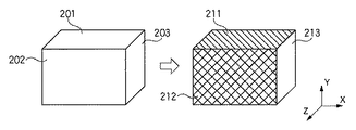
ここで、特性情報について説明する。図2は、面毎に特性情報を設定する様子を示す図である。同図では仮想物体として直方体を用いているが、同図を用いた特性情報設定技術の説明はこのような形状の仮想物体に限定するものではない。 Here, the characteristic information will be described. FIG. 2 is a diagram illustrating how characteristic information is set for each surface. In the figure, a rectangular parallelepiped is used as the virtual object, but the description of the characteristic information setting technique using the figure is not limited to the virtual object having such a shape.
同図において201から203はそれぞれこの仮想物体を構成する面(ポリゴン)で、それぞれに特性情報1,特性情報2,特性情報3を設定する。設定したものを色分けして表示したものが211〜213である。よってこのようにして仮想物体を構成する各部分(ここではポリゴン)について設定した特性情報がこのデータベース101に登録されている。なお、この特性情報は、仮想物体を構成する全てのポリゴンについて設定することに限定するものではなく、ユーザによって適宜設定すればよい。
In the figure,
図1に戻って、111はデータベース101,102のそれぞれに登録されているデータ群により構成されるデータベースで、各仮想物体について、仮想物体を描画するために必要なデータ群とこの仮想物体の各部分について設定された特性情報とのセットを管理する。
Returning to FIG. 1,
このセットデータにより、仮想物体A、仮想物体Bのデータを抽出したとする。112,113はそれぞれ仮想物体Aのセットデータ、仮想物体Bのセットデータである。ここで、仮想物体Aと仮想物体Bとは、それぞれが干渉しているのか否かを判断するために抽出されたものである。 It is assumed that data of the virtual object A and the virtual object B is extracted from the set data. 112 and 113 are set data of the virtual object A and set data of the virtual object B, respectively. Here, the virtual object A and the virtual object B are extracted in order to determine whether or not they interfere with each other.
この2つの仮想物体A、Bは仮想空間中に配置されるのであるが、所定の位置(予め決められた位置)に固定して配置しても良いし、予め決めた位置に配置し、その後予め決められた運動(回転、移動など)を行うようにしても良い。いずれにせよ、この2つの仮想物体A、仮想物体Bを仮想空間中に配置し、回転や移動などを行うのであれば回転、移動を行わせる。 These two virtual objects A and B are arranged in the virtual space, but they may be fixedly arranged at a predetermined position (predetermined position), or arranged at a predetermined position, and thereafter A predetermined motion (rotation, movement, etc.) may be performed. In any case, these two virtual objects A and B are arranged in the virtual space, and if they are rotated or moved, they are rotated and moved.
そしてこれら2つの仮想物体がそれぞれ干渉しているのか否かをチェックするのであるが、このチェック処理、及び干渉(衝突)の検出は衝突検出部115によって行われる。仮想物体同士が衝突しているのか否かの判定技術については周知の技術であるので、ここでの説明は省略する。
Then, it is checked whether or not these two virtual objects are interfering with each other. The
そして衝突している場合には干渉領域演算部116はそれぞれの仮想物体について、干渉している部分を検索する。例えば仮想物体A、仮想物体Bがそれぞれ図2に示したものであったとすると、仮想物体Aはポリゴン201でもって仮想物体Bと干渉しており(即ち干渉部分はポリゴン201)、仮想物体Bはポリゴン203でもって仮想物体Aと干渉している(即ち干渉部分はポリゴン203)場合には、干渉領域演算部116は、仮想物体Aにおける干渉部分はポリゴン201、仮想物体Bにおける干渉部分はポリゴン203と判断する。
When there is a collision, the interference
そして、所定の位置姿勢を有する視点から見た場合に見える仮想空間の画像を生成するのであるが、特性データ反映部117は、それぞれの仮想物体の画像を、干渉部分に設定された特性情報に基づいて生成する。より具体的には、例えば仮想物体Aにおける干渉部分はポリゴン201、仮想物体Bにおける干渉部分はポリゴン203であり、且つポリゴン101には特性情報1が設定されており、ポリゴン203には特性情報3が設定されており、且つ特性情報1に基づいて仮想物体の画像を生成する場合には「仮想物体全体を赤で描画する」、特性情報3に基づいて仮想物体の画像を生成する場合には「仮想物体全体を青で描画する」、というように予め決めている場合には、仮想物体A全体を赤一色で生成し、仮想物体B全体を青一色で生成する。
Then, an image of a virtual space that can be seen when viewed from a viewpoint having a predetermined position and orientation is generated. The characteristic
そして仮想物体表示部118は、このようにして生成されたそれぞれの仮想物体を仮想空間中に配置し、これを所定の位置姿勢を有する視点から見た場合に見える画像を生成して表示部505の表示画面上に表示する。
The virtual
これにより、衝突部分に応じて仮想物体A、仮想物体Bの色が変化するので、例え仮想物体Aが仮想物体Bに隠蔽されて干渉部分が見えなくても、仮想物体Aの一部でも見えていれば、その表示色を見れば、どの部分が干渉しているのかが分かる。なお、表示色の変更は仮想物体全体とすることに限定するものではなく、衝突部分のみ、衝突部分と同じテクスチャが張られている部分、衝突部分をその一部とするパーツ、というように、ある単位でもって表示色を変更するようにしても良い。 As a result, the colors of the virtual object A and the virtual object B change according to the collision part, so that even if the virtual object A is hidden by the virtual object B and the interference part is not visible, the virtual object A is also visible as a part of the virtual object A. If so, you can see which part is interfering by looking at the display color. The display color change is not limited to the entire virtual object, only the collision part, the part with the same texture as the collision part, the part with the collision part as a part, The display color may be changed in a certain unit.
なお、同図においてデータベースは全て外部記憶装置506内に設けられるものであり、衝突検出部115、干渉領域演算部116、特性データ反映部117、仮想物体表示部118は、CPU501の機能として動作する。
In the figure, all the databases are provided in the
図6は、仮想物体を構成する各部分に設定された特性情報によって、干渉部分を報知する処理のフローチャートである。なお、同図のフローチャートに従った処理をCPU501に行わせるためのプログラムやデータは外部記憶装置506に保存されており、これをCPU501による制御に従ってRAM502にロードし、これを用いてCPU501が処理を行うことで、本コンピュータは以下説明する各処理を実行することになる。
FIG. 6 is a flowchart of a process for notifying an interference part based on characteristic information set in each part constituting the virtual object. Note that programs and data for causing the
先ず、仮想物体の各部について設定された特性情報を外部記憶装置506からRAM502にロードする(ステップS601)。そして外部記憶装置506に保存されている各仮想物体の描画データを用いて2以上の仮想物体を仮想空間中に配置し(ステップS602)、配置した仮想物体を予め決まった規則でもって運動させ、その様子を予め決められた(若しくは操作部504を用いた操作指示により逐次変更可能な)位置姿勢の視点から見た場合に見える画像を生成して表示部505の表示画面上に表示する処理を行う(ステップS603)。
First, the characteristic information set for each part of the virtual object is loaded from the
なお、所定の状態における仮想空間を所定の位置姿勢を有する視点から見た場合に見える画像を生成する処理については周知の技術であるので、ここでの説明は省略する。 In addition, since it is a known technique about the process which produces | generates the image seen when the virtual space in a predetermined state is seen from the viewpoint which has a predetermined position and orientation, description here is abbreviate | omitted.
次に、CPU501は、衝突している(干渉している)仮想物体があるのかをチェックし(ステップS604)、なかった場合にはステップS603における処理を繰り返す。一方、衝突している仮想物体が存在する場合には処理をステップS605に進め、衝突している仮想物体(衝突仮想物体)のそれぞれについて、衝突している箇所を特定する処理を行う(ステップS605)。
Next, the
そして衝突仮想物体の衝突箇所に設定された特性情報に基づいて、この衝突箇所を報知する処理を、衝突仮想物体毎に行う(ステップS606)のであるが、報知方法には様々な方法があり、特に限定するものではないが、例えば、衝突仮想物体の衝突箇所に設定された特性情報に応じた色でもってこの衝突仮想物体のモデルを生成する処理を、衝突仮想物体毎に行う。 And based on the characteristic information set to the collision location of a collision virtual object, the process which alert | reports this collision location is performed for every collision virtual object (step S606), There exist various methods in an alerting | reporting method, Although not particularly limited, for example, a process of generating a model of the collision virtual object with a color corresponding to the characteristic information set at the collision location of the collision virtual object is performed for each collision virtual object.
報知方法についてはこのほかにも例えば、本コンピュータにスピーカを接続し、『特性情報1に基づいた音声「ポリゴンXが干渉しています」をスピーカを介して出力する、特性情報2に基づいた音声「ポリゴンYが干渉しています」をスピーカを介して出力する、特性情報3に基づいた音声「ポリゴンZが干渉しています」をスピーカを介して出力する』と予め決めており、且つ一方の衝突仮想物体の干渉部分に特性情報1が設定されており、他方の衝突仮想物体の干渉部分に特性情報3が設定されている場合には、「ポリゴンXが干渉しています」という音声と「ポリゴンZが干渉しています」という音声をスピーカを介して出力する。このように、予め設定した特性情報に基づいて干渉部分を報知する方法については特に限定するものではない。 In addition to the notification method, for example, a speaker is connected to the computer, and “sound based on characteristic information 1“ polygon X is interfering ”is output via the speaker. “Polygon Y is interfering” is output through the speaker, and the voice “Polygon Z is interfering” is output through the speaker based on the characteristic information 3 ”. When the characteristic information 1 is set in the interference part of the collision virtual object and the characteristic information 3 is set in the interference part of the other collision virtual object, the voice “polygon X is interfering” and “ The voice “polygon Z is interfering” is output through the speaker. As described above, the method for notifying the interference part based on the preset characteristic information is not particularly limited.
また、以上の例では特性情報はポリゴン毎に設定していたが、これに限定するものではなく、その他にも例えば、仮想物体にテクスチャマッピングを行う場合には、同じテクスチャ毎に特性情報を設定するようにしても良い。また、仮想物体が複数のパーツにより構成されている場合には、パーツ毎に特性情報を設定するようにしても良い。もちろん、このような場合であっても、特性情報に基づいた衝突部分の報知方法には上述のように様々なものが適用できる。 In the above example, the characteristic information is set for each polygon. However, the present invention is not limited to this. For example, when texture mapping is performed on a virtual object, the characteristic information is set for each same texture. You may make it do. When the virtual object is composed of a plurality of parts, the characteristic information may be set for each part. Of course, even in such a case, various methods as described above can be applied to the method of notifying the collision portion based on the characteristic information.
[第2の実施形態]
仮想物体を構成する各部分について特性情報を設定する方法については例えば以下のような方法がある。例えば、図2に示す仮想物体を例に取り説明すると、x軸に面するポリゴンには特性情報1、y軸に面するポリゴンには特性情報2、z軸に面するポリゴンには特性情報3をそれぞれ設定するようにしておけば、仮想物体を構成する各ポリゴンについてユーザが逐一設定することなく、CPU501側で設定することができる。なお、ポリゴンがどの軸にも面していない場合には、最も近い軸を探し、その軸に応じた特性情報を設定すればよい。
[Second Embodiment]
As a method for setting the characteristic information for each part constituting the virtual object, for example, there are the following methods. For example, taking the virtual object shown in FIG. 2 as an example, characteristic information 1 for a polygon facing the x axis, characteristic information 2 for a polygon facing the y axis, and characteristic information 3 for a polygon facing the z axis. Can be set on the
[第3の実施形態]
本実施形態では仮想物体を構成するポリゴンの頂点毎に特性情報を設定する。図3は、特性情報を頂点毎に設定する様子を示す図で、ここでは仮想物体として直方体を用いているが、同図を用いた特性情報設定技術の説明はこのような形状の仮想物体に限定するものではない。
[Third Embodiment]
In the present embodiment, characteristic information is set for each vertex of a polygon constituting a virtual object. FIG. 3 is a diagram showing how characteristic information is set for each vertex. Here, a rectangular parallelepiped is used as a virtual object, but the description of the characteristic information setting technique using this figure is for a virtual object having such a shape. It is not limited.
同図左側において、301,302,303はそれぞれポリゴンの頂点を示しており、これらの頂点に特性情報を設定するのであるが、同図右側において312,311,313はそれぞれ、各頂点301〜303について特性情報を設定した場合に、設定した特性情報が参照されうる範囲を示すものであり、例えば312で示す範囲内に衝突部分が存在した場合には頂点301に対して設定された特性情報に基づいて「頂点301が衝突部分であること」を報知する。
On the left side of the figure,
このように、特性情報は頂点単位で設定するようにしても良い。なお、仮想物体がポリゴンでなく、ボリュームデータやNURBS等でもって表現されるものである場合には、制御点毎、パーツ毎に特性情報を設定するようにしても良い。 Thus, the characteristic information may be set on a vertex basis. If the virtual object is not a polygon but is expressed by volume data, NURBS, or the like, characteristic information may be set for each control point and each part.
[第4の実施形態]
図4は、図3に示した仮想物体401(図3の右側に示すように、各頂点に特性情報が設定された仮想物体)が、仮想物体402と頂点301を干渉させながら、仮想物体402上を移動する様子を示す図で、本実施形態では仮想物体同士が干渉した場合には干渉した時点のそれぞれの干渉部分の位置をRAM502に記録する。
[Fourth Embodiment]
4 shows the
よって、RAM502に記録した位置群を順次記録順に線分で繋いで表示することで、同図に示す如く、その軌跡450を表示することができる。なお、頂点301に対して干渉部分となった場合に領域312が所定の色で表示されるように特性情報が設定されていると共に、仮想物体402を構成する面460に対しても干渉部分となった場合に表示色を指定するための特性情報が設定されているので、同図に示す如く、それぞれの領域は設定された特性情報に従った色でもって表示される。当然、衝突部分の報知方法は上述の通り、これに限定するものではない。
Therefore, by displaying the position groups recorded in the
[第5の実施形態]
図7は、仮想物体に対して特性情報を設定するためのGUIの表示例を示す図である。同図のGUIは表示部505の表示画面上に表示されるものである。同図において701は特性情報を設定する対象となる仮想物体を表示するための領域であり、特性情報を設定する箇所の選択はカーソル702でもって指示する。カーソル702の移動操作、及びカーソル702による指示操作は操作部504を用いた操作でもって行う。
[Fifth Embodiment]
FIG. 7 is a diagram illustrating a display example of a GUI for setting characteristic information for a virtual object. The GUI shown in the figure is displayed on the display screen of the
領域704には設定可能な特性情報が一覧表示されており、この表示された中から用いる特性情報を選択する。例えばカーソル702でもって仮想物体703のあるポリゴンを選択し、その後領域704内に表示された特性情報の中から、選択したポリゴンに対して設定する特性情報を指示する。同図では特性情報2が選択されており、その表示位置はハイライト表示されている。なお、操作手順は逆でも良い。
A list of characteristic information that can be set is displayed in the
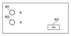
ここで、各特性情報が何を意味するのかについてはボタン画像705を指示することでその設定画面を表示することができる。CPU501はボタン画像705の指示を検知すると、表示部505の表示画面上に図8に示すGUIを表示する。図8は、特性情報によって干渉部分を色変化によって報知するのか、音声情報にて報知するのかを選択するためのGUIの表示例を示す図である。なお、上述の通り、報知方法はこれに限定するものではにので、その他の報知方法も適宜このGUIに追加するようにしても良い。
Here, as to what each characteristic information means, the setting screen can be displayed by instructing the
ここで801は報知方法を色変化とすべく選択するチェックボタンで、802は報知方法を音声情報でもって行うべく選択するチェックボタンである。ここで本コンピュータの操作者が操作部504を操作してチェックボタン801を指示した後にボタン画像803を指示すると、CPU501はこれを検知して表示部505の表示画面上に図9に示す画面を表示する。
Here,
図9は、各特性情報に対して、報知色を設定するためのGUIの表示例を示す図である。同図において領域902には設定可能な特性情報が一覧表示されており、この表示された中から1つ特性情報を選択した後に、メニュー901の中から色を1つ選択し、そして「設定」のボタン画像903を指示する。例えば領域902から「特性情報2」を選択した後に、メニュー901で「赤」を選択し、その後「設定」のボタン画像903を指示すると、「特性情報2を設定した部分(ポリゴン、頂点など)が衝突箇所となった場合には仮想物体全体、若しくはその一部を赤でもって生成する」というように設定することができる。これにより、色でもって衝突箇所を報知する為に特性情報を用いる場合には、用いる特性情報がどのような色でもって報知するのかを設定することができる。
FIG. 9 is a diagram illustrating a display example of a GUI for setting a notification color for each characteristic information. In the figure, a list of characteristic information that can be set is displayed in an
このように、用いる特性情報について色を設定する操作が完了し、ボタン画像904を指示すると、CPU501はこれを検知して表示部505の表示画面上に図7に示す画面を表示する。
Thus, when the operation for setting the color for the characteristic information to be used is completed and the
一方、図8に示したGUIにおいてチェックボタン802を指示すると、CPU501はこれを検知して表示部505の表示画面上に図10に示すGUIを表示する。
On the other hand, when the
図10は、各特性情報に対して、発声内容を設定するためのGUIの表示例を示す図である。同図において領域1002には設定可能な特性情報が一覧表示されており、この表示された中から1つ特性情報を選択した後に、入力領域1001内に発声内容を操作部504を用いて入力し、そして「設定」のボタン画像1003を指示する。例えば領域1002から「特性情報2」を選択した後に、領域1001内に「ポリゴンXが衝突箇所です」なる文章を入力し、その後「設定」のボタン画像1003を指示すると、『特性情報2を設定した部分(ポリゴン、頂点など)が衝突箇所となった場合には「ポリゴンXが衝突箇所です」なる音声出力がなされる』というように設定することができる。これにより、音声情報でもって衝突箇所を報知する為に特性情報を用いる場合には、用いる特性情報がどのような発声内容でもって報知するのかを設定することができる。
FIG. 10 is a diagram showing a display example of a GUI for setting the utterance content for each characteristic information. In the figure, a list of characteristic information that can be set is displayed in an
このように、用いる特性情報について発声内容を設定する操作が完了し、ボタン画像1004を指示すると、CPU501はこれを検知して表示部505の表示画面上に図7に示す画面を表示する。
As described above, when the operation for setting the utterance content for the characteristic information to be used is completed and the
以上の処理により、仮想物体に対して特性情報が設定できると共に、その特性情報による報知形態、及び報知内容についても設定することができる。 Through the above processing, the characteristic information can be set for the virtual object, and the notification form and the notification content based on the characteristic information can also be set.
[その他の実施形態]
また、本発明の目的は、前述した実施形態の機能を実現するソフトウェアのプログラムコードを記録した記録媒体(または記憶媒体)を、システムあるいは装置に供給し、そのシステムあるいは装置のコンピュータ(またはCPUやMPU)が記録媒体に格納されたプログラムコードを読み出し実行することによっても、達成されることは言うまでもない。この場合、記録媒体から読み出されたプログラムコード自体が前述した実施形態の機能を実現することになり、そのプログラムコードを記録した記録媒体は本発明を構成することになる。
[Other Embodiments]
Also, an object of the present invention is to supply a recording medium (or storage medium) in which a program code of software that realizes the functions of the above-described embodiments is recorded to a system or apparatus, and the computer (or CPU or Needless to say, this can also be achieved when the MPU) reads and executes the program code stored in the recording medium. In this case, the program code itself read from the recording medium realizes the functions of the above-described embodiment, and the recording medium on which the program code is recorded constitutes the present invention.
また、コンピュータが読み出したプログラムコードを実行することにより、前述した実施形態の機能が実現されるだけでなく、そのプログラムコードの指示に基づき、コンピュータ上で稼働しているオペレーティングシステム(OS)などが実際の処理の一部または全部を行い、その処理によって前述した実施形態の機能が実現される場合も含まれることは言うまでもない。 Further, by executing the program code read by the computer, not only the functions of the above-described embodiments are realized, but also an operating system (OS) running on the computer based on the instruction of the program code. It goes without saying that a case where the function of the above-described embodiment is realized by performing part or all of the actual processing and the processing is included.
さらに、記録媒体から読み出されたプログラムコードが、コンピュータに挿入された機能拡張カードやコンピュータに接続された機能拡張ユニットに備わるメモリに書込まれた後、そのプログラムコードの指示に基づき、その機能拡張カードや機能拡張ユニットに備わるCPUなどが実際の処理の一部または全部を行い、その処理によって前述した実施形態の機能が実現される場合も含まれることは言うまでもない。 Furthermore, after the program code read from the recording medium is written into a memory provided in a function expansion card inserted into the computer or a function expansion unit connected to the computer, the function is based on the instruction of the program code. It goes without saying that the CPU or the like provided in the expansion card or the function expansion unit performs part or all of the actual processing and the functions of the above-described embodiments are realized by the processing.
本発明を上記記録媒体に適用する場合、その記録媒体には、先に説明したフローチャートに対応するプログラムコードが格納されることになる。 When the present invention is applied to the recording medium, program code corresponding to the flowchart described above is stored in the recording medium.
Claims (5)
前記複数の仮想物体の形状データに基づき、視点の位置姿勢に応じた画像を生成する生成手段と、
前記複数の仮想物体の衝突および該仮想物体を構成するそれぞれの構成要素のうち衝突した構成要素を検出する検出手段とを有し、
前記生成手段は、衝突した仮想物体として前記検出手段が検出した仮想物体を衝突仮想物体とし、該衝突仮想物体を構成するそれぞれの構成要素のうち前記衝突した構成要素として前記検出手段が検出した構成要素を衝突構成要素とし、該衝突仮想物体を構成する全ての構成要素の色を、該衝突構成要素に対応する前記保持手段内の色情報が示す色に変更することで、該衝突仮想物体の全体の表示色を該色情報が示す色に変更した該衝突仮想物体の画像を生成することを特徴とする情報処理装置。 Holding means for holding each pre-correlated obtained color information of all the components comprising the plurality of shape data and the virtual object of a virtual object,
Generating means for generating an image according to the position and orientation of the viewpoint based on the shape data of the plurality of virtual objects;
Detecting means for detecting a collision of the plurality of virtual objects and a component which collided among the respective components constituting the virtual object;
Said generating means, a virtual object detected by the detection unit as a virtual object that has collided with the collision virtual object, said detecting means as a component that the collision among the respective components constituting the collision virtual object is detected By using the component as a collision component and changing the color of all the components constituting the collision virtual object to the color indicated by the color information in the holding means corresponding to the collision component , the collision virtual object An information processing apparatus that generates an image of the collision virtual object in which the display color of the entire image is changed to a color indicated by the color information.
前記複数の仮想物体の形状データに基づき、視点の位置姿勢に応じた画像を生成する生成工程と、
前記複数の仮想物体の衝突および該仮想物体を構成するそれぞれの構成要素のうち衝突した構成要素を検出する検出工程とを有し、
前記生成工程では、衝突した仮想物体として前記検出工程で検出した仮想物体を衝突仮想物体とし、該衝突仮想物体を構成するそれぞれの構成要素のうち前記衝突した構成要素として前記検出工程で検出された構成要素を衝突構成要素とし、該衝突仮想物体を構成する全ての構成要素の色を、該衝突構成要素に対応する前記保持手段内の色情報が示す色に変更することで、該衝突仮想物体の全体の表示色を該色情報が示す色に変更した該衝突仮想物体の画像を生成することを特徴とする情報処理方法。 An information processing method for an information processing apparatus performs having a holding means for holding each pre-correlated obtained color information of all the components comprising the plurality of shape data and the virtual object of a virtual object,
A generation step of generating an image according to the position and orientation of the viewpoint based on the shape data of the plurality of virtual objects;
Detecting a collision of the plurality of virtual objects and a component that collided among the respective components constituting the virtual object,
In the generation step, the virtual object detected in the detection step is used as a collision virtual object as a collided virtual object, and the collision component is detected in the detection step among the respective components constituting the collision virtual object . By using the component as a collision component and changing the color of all the components constituting the collision virtual object to the color indicated by the color information in the holding means corresponding to the collision component , the collision virtual object An information processing method comprising: generating an image of the collision virtual object in which an entire display color of the object is changed to a color indicated by the color information.
Priority Applications (1)
| Application Number | Priority Date | Filing Date | Title |
|---|---|---|---|
| JP2005123982A JP4756899B2 (en) | 2005-04-21 | 2005-04-21 | Information processing apparatus and information processing method |
Applications Claiming Priority (1)
| Application Number | Priority Date | Filing Date | Title |
|---|---|---|---|
| JP2005123982A JP4756899B2 (en) | 2005-04-21 | 2005-04-21 | Information processing apparatus and information processing method |
Publications (3)
| Publication Number | Publication Date |
|---|---|
| JP2006302035A JP2006302035A (en) | 2006-11-02 |
| JP2006302035A5 JP2006302035A5 (en) | 2008-06-05 |
| JP4756899B2 true JP4756899B2 (en) | 2011-08-24 |
Family
ID=37470236
Family Applications (1)
| Application Number | Title | Priority Date | Filing Date |
|---|---|---|---|
| JP2005123982A Expired - Fee Related JP4756899B2 (en) | 2005-04-21 | 2005-04-21 | Information processing apparatus and information processing method |
Country Status (1)
| Country | Link |
|---|---|
| JP (1) | JP4756899B2 (en) |
Cited By (1)
| Publication number | Priority date | Publication date | Assignee | Title |
|---|---|---|---|---|
| US10706625B2 (en) | 2015-07-06 | 2020-07-07 | Canon Kabushiki Kaisha | Information processing apparatus, control method, and storage medium storing program |
Families Citing this family (8)
| Publication number | Priority date | Publication date | Assignee | Title |
|---|---|---|---|---|
| JP4948273B2 (en) * | 2007-06-11 | 2012-06-06 | キヤノン株式会社 | Information processing method and information processing apparatus |
| JP4959518B2 (en) * | 2007-11-16 | 2012-06-27 | 株式会社Nykシステムズ | 3D CG object interference check program |
| JP6983939B2 (en) * | 2015-06-30 | 2021-12-17 | キヤノン株式会社 | Information processing equipment, information processing methods, programs |
| JP6676294B2 (en) * | 2015-06-30 | 2020-04-08 | キヤノン株式会社 | Information processing apparatus, information processing method, and program |
| JP2017142785A (en) | 2016-02-05 | 2017-08-17 | キヤノン株式会社 | Information processing device, information processing method and program |
| JP2019008623A (en) | 2017-06-27 | 2019-01-17 | キヤノン株式会社 | Information processing apparatus, information processing apparatus control method, computer program, and storage medium |
| WO2020217440A1 (en) * | 2019-04-26 | 2020-10-29 | 三菱電機エンジニアリング株式会社 | Collision sensing device |
| WO2021024367A1 (en) * | 2019-08-06 | 2021-02-11 | インテグラル・テクノロジー株式会社 | Shape data processing device, shape data processing method, and shape data processing program |
Citations (3)
| Publication number | Priority date | Publication date | Assignee | Title |
|---|---|---|---|---|
| JP2001209417A (en) * | 1998-06-01 | 2001-08-03 | Amada Co Ltd | Automatic programming system and recorded medium recording sheet metal graphic generation program |
| JP2004178006A (en) * | 2002-11-22 | 2004-06-24 | Ricoh Co Ltd | Three-dimensional shape processing apparatus, model interference section display method, program and storage medium therefor |
| JP2004310591A (en) * | 2003-04-09 | 2004-11-04 | Toyota Motor Corp | Layout design device, and layout design method |
-
2005
- 2005-04-21 JP JP2005123982A patent/JP4756899B2/en not_active Expired - Fee Related
Patent Citations (3)
| Publication number | Priority date | Publication date | Assignee | Title |
|---|---|---|---|---|
| JP2001209417A (en) * | 1998-06-01 | 2001-08-03 | Amada Co Ltd | Automatic programming system and recorded medium recording sheet metal graphic generation program |
| JP2004178006A (en) * | 2002-11-22 | 2004-06-24 | Ricoh Co Ltd | Three-dimensional shape processing apparatus, model interference section display method, program and storage medium therefor |
| JP2004310591A (en) * | 2003-04-09 | 2004-11-04 | Toyota Motor Corp | Layout design device, and layout design method |
Cited By (1)
| Publication number | Priority date | Publication date | Assignee | Title |
|---|---|---|---|---|
| US10706625B2 (en) | 2015-07-06 | 2020-07-07 | Canon Kabushiki Kaisha | Information processing apparatus, control method, and storage medium storing program |
Also Published As
| Publication number | Publication date |
|---|---|
| JP2006302035A (en) | 2006-11-02 |
Similar Documents
| Publication | Publication Date | Title |
|---|---|---|
| JP4756899B2 (en) | Information processing apparatus and information processing method | |
| JP3689226B2 (en) | Decomposition path generator | |
| US9976852B2 (en) | Inspection program editing environment providing user defined collision avoidance volumes with integral modification properties | |
| JP5953382B2 (en) | Annotation method for 3D model and non-transitory program storage medium readable by computer | |
| KR101863041B1 (en) | Creation of playable scene with an authoring system | |
| JP2018041441A (en) | Generation of color of object displayed on gui | |
| US7420556B2 (en) | Information processing method and information processing apparatus | |
| JPH10283158A (en) | Stereoscopic display device for window and method therefor | |
| Himperich | Applications in augmented reality in the automotive industry | |
| US8823706B2 (en) | Method, program and product edition system for visualizing objects displayed on a computer screen | |
| JP2010277115A (en) | Harness verification device and harness verification program | |
| JP3437223B2 (en) | Shape display device and shape display method | |
| EP3594906B1 (en) | Method and device for providing augmented reality, and computer program | |
| JP2006215750A (en) | Image processing method, image processor | |
| US8145460B2 (en) | Information processing method and information processing apparatus | |
| JP2007213437A (en) | Information-processing method and information-processing device | |
| JP2007249561A (en) | Display system and program of screen transition diagram | |
| JPH0816825A (en) | Method and device for editing three-dimensional solid arrangement | |
| JP6264208B2 (en) | Display program, display method, and display device | |
| US20070182759A1 (en) | Graphics processing apparatus, method and program storage medium thereof | |
| JPH0981784A (en) | Three-dimensional object selection device | |
| JP4086601B2 (en) | Three-dimensional shape measurement result display device, three-dimensional shape measurement result display method, program, and recording medium | |
| JP2009058991A (en) | Window display system, method, and program | |
| JPH07271998A (en) | Method and device for three-dimensional display | |
| JP4198412B2 (en) | Three-dimensional shape data processing apparatus, three-dimensional shape data processing method, recording medium, and program |
Legal Events
| Date | Code | Title | Description |
|---|---|---|---|
| A521 | Written amendment |
Free format text: JAPANESE INTERMEDIATE CODE: A523 Effective date: 20080421 |
|
| A621 | Written request for application examination |
Free format text: JAPANESE INTERMEDIATE CODE: A621 Effective date: 20080421 |
|
| A977 | Report on retrieval |
Free format text: JAPANESE INTERMEDIATE CODE: A971007 Effective date: 20101209 |
|
| A131 | Notification of reasons for refusal |
Free format text: JAPANESE INTERMEDIATE CODE: A131 Effective date: 20101217 |
|
| A521 | Written amendment |
Free format text: JAPANESE INTERMEDIATE CODE: A523 Effective date: 20110210 |
|
| A131 | Notification of reasons for refusal |
Free format text: JAPANESE INTERMEDIATE CODE: A131 Effective date: 20110228 |
|
| A521 | Written amendment |
Free format text: JAPANESE INTERMEDIATE CODE: A523 Effective date: 20110426 |
|
| TRDD | Decision of grant or rejection written | ||
| A01 | Written decision to grant a patent or to grant a registration (utility model) |
Free format text: JAPANESE INTERMEDIATE CODE: A01 Effective date: 20110520 |
|
| A01 | Written decision to grant a patent or to grant a registration (utility model) |
Free format text: JAPANESE INTERMEDIATE CODE: A01 |
|
| A61 | First payment of annual fees (during grant procedure) |
Free format text: JAPANESE INTERMEDIATE CODE: A61 Effective date: 20110531 |
|
| R150 | Certificate of patent or registration of utility model |
Ref document number: 4756899 Country of ref document: JP Free format text: JAPANESE INTERMEDIATE CODE: R150 Free format text: JAPANESE INTERMEDIATE CODE: R150 |
|
| FPAY | Renewal fee payment (event date is renewal date of database) |
Free format text: PAYMENT UNTIL: 20140610 Year of fee payment: 3 |
|
| LAPS | Cancellation because of no payment of annual fees |