JP4756788B2 - Image processing apparatus and image processing method - Google Patents
Image processing apparatus and image processing method Download PDFInfo
- Publication number
- JP4756788B2 JP4756788B2 JP2001244072A JP2001244072A JP4756788B2 JP 4756788 B2 JP4756788 B2 JP 4756788B2 JP 2001244072 A JP2001244072 A JP 2001244072A JP 2001244072 A JP2001244072 A JP 2001244072A JP 4756788 B2 JP4756788 B2 JP 4756788B2
- Authority
- JP
- Japan
- Prior art keywords
- image
- images
- information
- arrangement
- Prior art date
- Legal status (The legal status is an assumption and is not a legal conclusion. Google has not performed a legal analysis and makes no representation as to the accuracy of the status listed.)
- Expired - Fee Related
Links
Images


Description
【0001】
【発明の属する技術分野】
本発明は、例えば、静止画を記録するスチルカメラやビデオカメラ等により撮像して得られた電子情報(画像及びその付帯情報)を、熱転写式プリンタやインクジェットプリンタ等のプリンタでプリント出力するための装置或いはシステムに用いられる、画像処理装置及び画像処理方法に関するものである。
【0002】
【従来の技術】
従来より例えば、画像入力装置から入力した複数の画像を一枚の用紙に配置して印刷する印刷システムでは、次に説明するような画像配置方法(1)及び(2)が一般的に用いられている。
【0003】
画像配置方法(1):
当該方法は、利用者が一枚の用紙に印刷する画像の数を指定すると、印刷システムが画像を適当な大きさに自動的に配置する方法である。当該方法は、多数の画像を一覧するために用紙上に印刷する場合や、印刷後に用紙を切り離して同じサイズに印刷する場合に利用されることが多い。
当該方法を用いる印刷システムででは、用紙として、例えば、16分割シール用紙が一般的に用いられている。この16分割シール用紙は、用紙が縦4ブロック、横4ブロックの合計16ブロックに分割されており、それぞれをシールとして利用できるものである。また、印刷後に所望するブロックを切り取ることができるように、予めミシン目が用意されているものもある。このような用紙に画像を同時に複数印刷することで、用紙や印刷時間の無駄を省くことができる。
当該方法を用いた印刷システムでは、自動的に画像の方向を回転したり、或いはトリミングすることで、全ての画像が同じサイズで印刷可能領域全体に印刷されるように配置するように構成されているのが一般的である。
【0004】
画像配置方法(2):
当該方法は、利用者が全ての画像に対して印刷位置、サイズ 及び方向を指定し、この指定に従って配置する方法である。当該方法では、全画像に対して配置を指定する作業が必要であるが、利用者の好みに応じて自由に配置を変更できる。
当該方法を用いた印刷システムにより、例えば、印刷したスナップ写真を後からアルバム用紙に貼り付けたのと同様の印刷結果が得られる。したがって、同じレイアウトのアルバムを2部以上印刷する場合等の労力を大幅に減らすことができる。
【0005】
また、画像と共に記録された付帯情報を、当該画像を印刷するときに一緒に印刷する印刷システムもある。例えば、付帯情報を撮影日時情報とした場合、カメラで撮影した画像を、当該画像の撮影日時と共に印刷できるため、当該画像が撮影された日時を印刷結果を見るだけで容易に把握できる。
このような印刷システムとしては、画像周囲の余白の決まった部分に付帯情報を印字する印刷システムや、画像上の画像に重なる位置に付帯情報を印字する印刷システム等がある。また、実際に用紙に画像及びその付帯情報を印刷する前に、当該付帯情報の印字位置を調整できるものもある。
【0006】
印刷システムで用いられるプリンタとしては、熱転写方式のプリンタや、インクジェットプリンタ等が挙げられる。
例えば、インクジェットプリンタとしては、液滴の小ドット化等の技術が進み、より高画質なものが登場している。また、熱転写方式のプリンタとしては、従来から印画用紙として感熱型の用紙を用い、主走査方向に配列された複数個の発熱体を選択的に駆動して当該用紙を副走査方向に搬送することで、当該用紙にドットライン状に印画を行うライン熱転写方式のプリンタがある。
【0007】
熱転写方式のプリンタは、近年、画像入力側としてのディジタルカメラやディジタルビデオカメラ、或いはスキャナ等の画像を扱う入力機器の進歩に伴い、プリント手段として注目されている。この主なる理由としては、次のようなことが挙げられる。
まず、インクジェットプリンタは、液滴を飛ばすか飛ばさないか、という2値の選択しかないために、小さな液滴を用紙へ着弾させて、誤差拡散等の手法により、見かけの解像度及び階調性を得るように構成されている。これに対して、熱転写方式のプリンタは、1つの画素に対して、制御可能な熱の値を容易に変更できるため、1つの画素に対する階調性が多く取ることが可能となるため、インクジェットプリンタと比較して、滑らかで高画質な画像を得ることができる。また、サーマルヘッドの性能や用紙材料の性能も向上していることにより、熱転写方式のプリンタは、仕上がり品位で銀塩写真にも見劣りしない画像プリントを得ることが可能であり、近年のディジタルカメラ等の進歩に歩調を合わせるように、特に自然画像用のプリンタとして注目されている。
【0008】
したがって、印刷システム(プリントシステム)では、上述のようなプリンタと、ディジタルカメラやディジタルビデオカメラ等の画像入力機器とを直接的に接続する、或いはまたは一体的に構成し、画像入力機器から入力される画像情報を、コンピューター等の画像情報を処理する機器を介すことなく、プリンタでプリントが可能となる。これにより、ディジタルカメラやディジタルビデオ等で得られた画像情報を、簡単に写真的にプリントアウトを行うことが可能となり、大変便利である。
【0009】
印刷システムの具体例としては、例えば、特開平10−243327号公報等に記載された画像入出力システムがある。
当該画像入出力システムは、画像出力装置と画像入力装置を接続してなるシステムである。画像出力装置は、画像入力装置からの画像信号を受信して出力すると共に、画像入力装置に対して電力を供給する電源部を有する。画像入力装置は、画像出力装置に対して画像データを送信し、且つ画像出力装置から電源電力の供給を受けるための接続ケーブルにより、画像出力装置と接続されている。また、画像入力装置は、画像出力装置から電力供給を受けることの可否を判定する判定手段、及び電源部を備え、判定手段により、画像出力装置から電力供給を受けられると判定された場合には画像出力装置からの電力を用い、電力供給を受けられないと判定された場合には電源部からの電力を用いるように構成されている。
当該画像入出力システムによれば、画像出力装置から電力の供給が受けられるため、ディジタルカメラ等の画像入力装置の電源の残量を気にすることなく、プリント出力できるため、非常に効果的である。
【0010】
また、例えば、特開平9−65182号公報等に記載された複合カメラがある。当該復号カメラは、特に、プリント時の電力省電に特徴がある。
当該復号カメラは、電子ビューファインダを有し、且つ映像情報を記録媒体へ記録する撮影手段、及び映像情報を記録紙へプリント出力するプリンタ手段を一体化したカメラであり、さらに、プリンタ手段が記録紙へ映像情報をプリント出力している間は、上記電子ビューファインダへ電力を供給するのを停止するよう制御する制御手段を備えている。
当該復号カメラによれば、プリント中は電子ビューファインダへの電力供給をしないので、節電に役立ち、非常に効果的である。
【0011】
【発明が解決しようとする課題】
しかしながら、上述したような従来の印刷システムでは、特に、画像と共に記録された付帯情報を当該画像の印刷時に同時に印刷するように構成された従来の印刷システムでは、付帯情報の印刷位置と画像の配置方法の組み合わせによっては、用途に適さない印刷結果が得られる場合がある。
【0012】
具体的には例えば、画像を適当な大きさに自動的に配置して印刷する方法を使い、且つ画像の付帯情報を余白に印刷するようになされた印刷システムにおいて、印刷後に、用紙を切り離してそれぞれの印刷画像を配布する用途に使用する場合、配布される切離用紙上に画像と共に付帯情報が印刷された状態とするために、全ての画像の付帯情報の印刷位置を手で変更する、或いは画像を印刷するサイズを印刷可能領域より小さくする必要がある。
また、例えば、利用者の好みに応じて各画像の印刷位置やサイズを指定して印刷する方法を使い、且つ画像の付帯情報を画像に重なる位置に印刷するようになされた印刷システムでは、付帯情報によって画像の一部が隠れてしまわないような印刷結果を得るために、全ての画像の付帯情報の印刷位置を手で変更する必要がある。
【0013】
また、上述したような従来の印刷システムにおいて、例えば、図17に示すように、画像910,920,930,940をできるだけ余白を設けないで大きく印刷し、且つ撮影日付等の付帯情報911,921,931,941をも同時に印刷したい場合、付帯情報911,921,931,941を印刷するための余白を設ける必要があるため、その分、画像が小さくなってしまう。
これとは逆に、例えば、図18に示すように、画像950,960,970,980のそれぞれは小さくてもよいが、縦方向で撮影された画像については90度回転させる等して多くの画像を一覧できるようにしたい場合、その分の余白が多く生じる上に、日付情報により、ただでさえ小さな画像が更に小さくなり見づらくなってしまう。
【0014】
また、特開平10−243327号公報等に記載された従来の画像入出力システムや、特開平9−65182号公報等に記載された従来の複合カメラにより、印刷システムを構成した場合であっても、利用者(ユーザ)に十分な満足を与えることができなかった。
具体的には、撮影日付等の付帯情報を画像と共に印刷しようとした場合、銀塩写真の場合と同様に、付帯情報を画像の一部に重ねて印刷出力するのが一般的であった。この場合、付帯情報(撮影日付を示す文字列等)の出力位置及び向きは、画像によらず一定であり、余白部分が十分にある場合であっても、付帯情報が画像に重なり合って印刷出力されてしまうため、画像が非常に見づらくなってしまう、或いは画像の向きと付帯情報の向きが異なるため不自然さがある、などと言う不具合があった。
このように、従来では、利用者にとって使い勝手の良い印刷システムを提供することができていなかった。
【0015】
そこで、本発明は、上記の欠点を除去するために成されたもので、画像及びその付帯情報を印刷する際に、当該付帯情報を適切な位置及び方向で印刷する構成により、利用者が効率良く印刷作業を行え、所望する印刷物を容易に且つ確実に取得できるようにすることを目的とする。
【0016】
【課題を解決するための手段】
本発明の画像処理装置は、複数の画像と当該複数の画像の付帯情報とを記録媒体上の複数の印刷領域に配置してプリントするための画像処理装置であって、前記複数の印刷領域に配置される画像それぞれについて、印刷領域の長辺方向と画像の長辺方向が一致するように画像を回転させ、さらに、印刷領域の縦横比と同じ縦横比となるように画像をトリミングし、トリミングした画像が前記印刷領域全体に印刷されるように前記トリミングした画像を変倍して配置する第1の配置方法と、画像の回転及びトリミングをせずに前記複数の画像を前記複数の印刷領域に配置する第2の配置方法とから、前記複数の画像の配置方法を選択する選択手段と、前記選択手段により第1の配置方法が選択された場合には、画像内に前記複数の画像の付帯情報を配置し、前記選択手段により第2の配置方法が選択された場合には、前記複数の画像の付帯情報を、前記複数の画像を配置した結果存在する画像外の余白部分に配置する配置制御手段とを有することを特徴とする。
本発明の画像処理方法は、複数の画像と当該複数の画像の付帯情報とを記録媒体上の複数の印刷領域に配置してプリントするための画像処理方法であって、前記複数の印刷領域に配置される画像それぞれについて、印刷領域の長辺方向と画像の長辺方向が一致するように画像を回転させ、さらに、印刷領域の縦横比と同じ縦横比となるように画像をトリミングし、トリミングした画像が前記印刷領域全体に印刷されるように前記トリミングした画像を変倍して配置する第1の配置方法と、画像の回転及びトリミングをせずに前記複数の画像を前記複数の印刷領域に配置する第2の配置方法とから、前記複数の画像の配置方法を選択手段によりユーザに選択させるための選択工程と、制御手段により実行される配置制御工程であって、前記選択工程で第1の配置方法が選択された場合には、画像内に前記複数の画像の付帯情報を配置し、前記選択工程で第2の配置方法が選択された場合には、前記複数の画像の付帯情報を、前記複数の画像を配置した結果存在する画像外の余白部分に配置する配置制御工程とを有することを特徴とする。
【0051】
【発明の実施の形態】
以下、本発明の実施の形態について図面を用いて説明する。
【0052】
[第1の実施の形態]
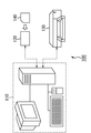
本発明は、例えば、図1に示すような印刷システム100に適用される。
本実施の形態の印刷システム100は、上記図1に示すように、制御装置110、読取装置120、及びプリンタ130を含んでいる。
【0053】
制御装置110は、利用者からの入力を受け付けると共に、利用者に対する出力、及び自装置に接続されている機器或いはシステムの制御等を行う。
読取装置120は、画像等の情報が記録された記録媒体104から当該情報を読み出す。
プリンタ130は、画像等を用紙に印刷する。
読取装置120及びプリンタ130はそれぞれ、例えば、USBインターフェイスを介して制御装置110に接続されている。
【0054】
図2は、制御装置110の内部構成を示したものである。
制御装置110は、上記図2に示すように、コンピュータ装置111、USBインターフェイス112、ハードディスク113、マウス114、モニタ115、及びキーボード116を含んでいる。
【0055】
コンピュータ装置111は、複数のUSB機器が接続可能なUSBインターフェイス112、及びハードディスク113を内蔵している。
また、コンピュータ装置111には、モニタ115が接続されていると共に、USBインターフェイス経由でマウス114及びキーボード116が接続されている。
印刷システム100の利用者は、マウス114やキーボード116を使用して制御装置101の動作指示(動作変更指示等)を行うことができる。
【0056】
ハードディスク113には、例えば、上記図1に示した記録媒体140から読み取られた画像がJPEG形式のファイルとして保存されると共に、当該保存画像のそれぞれの配置情報がテーブル形式で保存される。
具体的には例えば、上記図1において、読取装置120に対して記録媒体140がセットされると、読取装置120は、記録媒体140に記録されている画像及びその付帯情報等を読み取る。制御装置110(主にコンピュータ装置111)は、読取装置120による読取情報をハードディスク113に保存すると共に、当該読取情報に基づきハードディスク113内のテーブル情報(配置情報)を全て更新する。
【0057】
図6は、ハードディスク113に保存される、画像の配置情報のテーブル200の一例を示したものである。
テーブル200には、画像番号(201)、画像ファイル名(202)、画像のあるページ番号(203)、画像のトリミング領域左端座標(204)、画像のトリミング領域上端座標(205)、画像のトリミング領域右端座標(206)、画像のトリミング領域下端座標(207)、画像の中心の横方向位置(208)、画像の中心の縦方向位置(209)、画像の表示倍率(210)、画像の回転角(211)、及び付帯情報の文字列(212)を配置情報として記録される。
【0058】
上述のような制御装置110は、画像を適当な大きさに自動的に配置して印刷する固定レイアウトモードと、利用者の好みに応じて各画像の印刷位置やサイズを指定して印刷する自由レイアウトモードとの2つの画像配置モードを有し、利用者からの画像配置モードの切り替えに基づき一部異なる動作を行う。
【0059】
図4は、本実施の形態における印刷システム100の制御装置110の動作として、画像配置モードによらない共通な基本的な動作を示したものである。
【0060】
ステップS301:
制御装置110において、先ず、コンピュータ装置111は、読取装置120に対して記録媒体140がセットされているか否かを確認し、記録媒体140がセットされている場合に、読取装置120により、記録媒体140に記録されている全ての画像データを読み取ってハードードディスク113にコピーする。その後、コンピュータ装置111は、ハードードディスク113内のテーブル200(上記図3参照)において、画像番号(201)及び画像ファイル名(202)の記録を行うと共に、読取画像に対して撮影日時等の付帯情報が記録されているものについては、これを文字列として付帯情報の文字列(212)に記録する。
【0061】
ステップS302:
コンピュータ装置111は、画像の配置情報を初期化し、この結果をハードディスク113のテーブル200に記録する。画像の配置情報の初期値としては、詳細は後述するが、画像配置モードに応じた2通りの初期値が用いられる。
ステップS303:
コンピュータ装置111は、ハードディスク113のテーブルに記録された画像の配置情報を変更するための配置情報更新画面をモニタ115に表示する。
ステップS304:
コンピュータ装置111は、配置情報更新画面のモニタ115への表示が終了すると、マウス114又はキーボード116による利用者からの操作入力を待ち、当該入力があった場合に、次のステップS305に進む。
【0062】
ステップS305:
コンピュータ装置111は、ステップS304における入力が、画像の配置情報の変更であるか否かを判別し、この判別の結果、画像の配置情報の変更である場合にはステップS306に進み、そうでない場合にはステップS307に進む。
【0063】
ステップS306:
ステップS305の判別の結果、画像の配置情報の変更入力があった場合、コンピュータ装置111は、当該変更入力に基づいた情報をハードディスク113のテーブル200に記録し、再びステップS303に戻り、以降の処理ステップを繰り返し実行する。
【0064】
ステップS307:
ステップS305の判別の結果、画像の配置情報の変更入力でない場合、コンピュータ装置111は、利用者の入力が、画像配置モードの切替指示入力であるか否かを判別し、この判別の結果、画像配置モードの切替指示入力である場合には再びステップS302(配置情報の初期化)に戻り以降の処理ステップを繰り返し実行し、そうでない場合にはステップS308に進む。
【0065】
ステップS308:
ステップS307の判別の結果、画像配置モードの切替指示入力でない場合、コンピュータ装置111は、利用者の入力が、印刷指示入力であるか否かを判別し、この判別の結果、印刷指示入力でない場合には再びステップS304に戻り以降の処理ステップを繰り返し実行し、印刷指示入力である場合にはステップS309に進む。
【0066】
ステップS309:
ステップS308の判別の結果、印刷指示入力である場合、コンピュータ装置111は、プリンタ130に対して、ハードディスク113に記録された画像及びその配置情報を用いた印刷を指示する。
その後、本処理終了となる。
【0067】
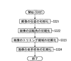
ここで、上記図4に示したステップS302では、画像の配置情報の初期値として、その時点での画像配置モードに応じた異なる値が設定される。
図5は、当該ステップS302における画像の配置情報初期化の詳細な手順を示したものである。
【0068】
ステップS321:
画像の位置の初期化を行う。
例えば、用紙の左上、右上、左下、及び右下のそれぞれに4つの画像が配置されるように、画像のあるページ番号(203)、画像の中心の横方向位置(208)、及び画像の中心の縦方向位置(209)の3つの初期値を設定する。
【0069】
ステップS322:
画像の回転角の初期化を行う。
例えば、自由レイアウトモードでは、初期値としては回転を行わないため、画像の回転角(211)に対して“0”を設定する。一方、固定レイアウトモードでは、画像の長辺方向と用紙の印刷範囲の長辺方向が一致するように、0度又は90度の回転を行うため、縦長の印刷領域に印刷する場合、縦長の画像の回転角(211)に“0”を設定し、横長の画像の回転角(211)に“90”を設定する。
【0070】
ステップS323:
画像のトリミング領域の初期化を行う。
例えば、自由レイアウトモードでは、初期値としてトリミングを行わないため、画像のトリミング領域左端座標(204)、及び画像のトリミング領域上端座標(205)に対してそれぞれ“0”を設定し、画像のトリミング領域右端座標(206)、及び画像のトリミング領域下端座標(207)に対して画像ファイルの幅と高さを設定する。一方、固定レイアウトモードでは、必ず印刷領域と同じ縦横比となるようにトリミングを行うので、初期値として、上下端或いは左右端の何れかのみを等分にトリミングし、切り捨てられる領域が最小となるような値を、画像のトリミング領域左端座標(204)、画像のトリミング領域上端座標(205)、画像のトリミング領域右端座標(206)、及び画像のトリミング領域下端座標(207)に設定する。
【0071】
ステップS324:
画像の表示倍率の初期化を行う。
例えば、自由レイアウトモードでは、画像が用紙全体の印刷可能領域の4分の1(幅2分の1、高さ2分の1)の領域よりさらに10%小さくなるような値を、画像の表示倍率(210)に設定する。一方、固定レイアウトモードでは、画像が用紙全体の印刷可能領域の4分の1(幅2分の1、高さ2分の1)の領域全体に印刷されるような値を、画像の表示倍率(210)に設定する。
【0072】
図6は、上記図4に示したステップS303においてモニタ115で表示される配置情報更新画面220の一例を示したものである。
【0073】
上記図6において、“221”は、ハードディスク113に記録されている画像の配置情報のテーブル200(上記図3)に対応したテーブル一覧情報が表示されるテーブル領域である。利用者は、例えば、マウス114により、テーブル領域221において更新したい項目を選択し、キーボード116により、当該項目内の値を更新可能である。
【0074】
“222”は、スクロールバーであり、テーブル領域221でテーブル200の全ての情報を一度に表示しきれない場合に有効となる。この場合、利用者は、スクロールバー222を操作することで、テーブル領域221をスクロールさせて、所望する情報を参照及び変更することができる。
【0075】
“223”は、切替ボタンであり、印刷システム100の画像配置モードを固定レイアウトモード又は自由レイアウトモードに変更できるようになされている。
“224”は、印刷ボタンであり、印刷ボタン224の操作のタイミングで、テーブル200の配置情報に基づき該当するデータが印刷装置130に対して送信される。
【0076】
利用者によるテーブル領域221における情報変更について、利用者からの入力値が有効な値でない場合、例えば、画像の中心の縦方向位置(209)に対して用紙の印刷範囲外の値が入力された、或いは画像の回転角(211)に対して“90”の倍数以外の値が入力された場合、その入力は無視される。また、1つの項目の値が変更されると、同じ画像の他の項目を同時に変更する必要がある場合、例えば、固定レイアウトモードで画像の表示倍率(210)が大きく変更された場合、画像を印刷領域外に印刷することのないように、自動的に、画像のトリミング領域左端座標(204)、画像のトリミング領域上端座標(205)、画像のトリミング領域右端座標(206)、及び画像のトリミング領域下端座標(207)がそれぞれ調整変更される。
【0077】
尚、本実施の形態では、配置情報更新画面220のテーブル領域221において、変更値を直接入力するように構成しているが、これに限られることはなく、例えば、用紙に実際に印刷される画像の配置をグラフィカルに表示し、マウス114のドラッグ操作等により、当該画像の配置情報を変更可能なインターフェイスを用いることも可能である。
【0078】
図7は、上記図4に示したステップS309における印刷処理の詳細な手順を示したものである。
【0079】
ステップS341:
ハードディスク113に対して、プリンタ130に送信する印刷データを一時的に保存するためのデータ領域を準備する。
【0080】
ステップS342〜ステップS350の処理は、ハードディスク113内のテーブル200に記録されている全ての配置情報について順に実行される。
【0081】
ステップS342:
ハードディスク113内のテーブル200から、対象となる画像の配置情報から順に読み出す。
ステップS343:
ステップS342で読み出した配置情報の画像ファイル名(202)で指定された画像データをハードディスク113から読み出す。
【0082】
ステップS344:
ステップS342で読み出した画像データに対して、ステップS342で読み出した配置情報の、画像のトリミング領域左端座標(204)、画像のトリミング領域上端座標(205)、画像のトリミング領域右端座標(206)、及び画像のトリミング領域下端座標(207)に基づいてトリミングを行い、さらに、当該トリミング後の画像データに対して、上記配置情報の画像の表示倍率(210)に従って拡大処理を施し、さらにまた、当該処理後の画像データに対して、上記配置情報の回転角(211)で指定された角度回転を施す。そして、このような加工後の画像データを印刷データとして、上記配置情報の画像のあるページ番号(203)で指定されたページの、上記配置情報の画像の中心の横方向位置(208)及び画像の中心の縦方向位置(209)で指定された位置に配置するように、ステップS341で準備したハードディスク113のデータ領域に記録する。
【0083】
ステップS345:
上記配置情報の付帯情報の文字列(212)に情報が記録されているか否かを判別し、この判別の結果、情報記録されている場合にはステップS346に進み、そうでない場合にはステップS349に進む。
【0084】
ステップS346:
ステップS345の判別の結果、付帯情報の文字列(212)に情報が記録されている場合、現在の画像配置モードを調べ、自由レイアウトモードの場合にはステップS348に進み、固定レイアウトモードの場合はステップS347に進む。
【0085】
ステップS347:
ステップS346のチェックの結果、現在の画像配置モードが固定レイアウトモードである場合、ステップS344でハードディスク113のデータ領域に記録した印刷データに対して、画像の付帯情報を画像に重ねて印刷するように変更をかける。このとき、付帯情報の文字列の印刷位置及び方向を、上記配置情報の画像の回転角(211)に応じて変更する。
これにより、例えば、回転角が0度の場合、画像の左下から右下に向かって文字列は回転されずに印刷される。回転角が90度の場合、画像の左上から左下に向かって、文字列が90度回転して印刷される。回転角が180度の場合、画像の右上から左上に向かって、文字列が180度回転して印刷される。回転角が270度の場合、画像の右下から右上に向かって、文字列が270度回転して印刷される。
【0086】
ステップS348:
ステップS346のチェックの結果、現在の画像配置モードが自由レイアウトモードである場合、ステップS344でハードディスク113のデータ領域に記録した印刷データに対して、画像の付帯情報を画像の外に印刷するように変更をかける。このとき、付帯情報の文字列の印刷位置を画像のすぐ下とし、文字列を回転しないようにする。
【0087】
ステップS349:
ステップS347又はステップS348の処理後、ハードディスク113のテーブル200において、現在処理対象としている画像の配置情報、及びこれに対応する画像データファイルを削除する。
ステップS350:
ハードディスク113のテーブル200において、処理すべき画像の配置情報が未だ残っているか否かを判別する。すなわち、テーブル200の配置情報が全て削除されて空になったか否かを判別する。この判別の結果、未だ配置情報が存在する場合には、再びステップS342戻り、当該配置情報についての処理を繰り返し実行する。一方、全ての配置情報を処理終了した場合には、ハードディスク113に記録された印刷データをプリンタ130に送信し、その後、本処理終了とする。
【0088】
以下に、上述したような印刷システム100による効果の一例を挙げる。
【0089】
例えば、上記図17に示したように、画像910,920,930,940をできるだけ余白を設けないで大きく印刷し、且つ撮影日付等の付帯情報911,921,931,941をも同時に印刷したい場合で、固定レイアウトモードにより当該印刷を行った場合、画像910,920,930,940のそれぞれは、テーブル200に画像の配置情報に従って、用紙上に印刷される。
ここでの印刷対象の用紙としては、横1200画素×縦1600画素が印刷可能な用紙を用いている。
【0090】
画像910は、横800画素×縦600画素の画像である。画像910を、上記図5に示したような手順で用紙上の左上に配置した場合、画像910の中心位置(300,400)、回転角90度、トリミング領域(0,0)−(800,600)、表示倍率100%となる。また、画像910の付帯情報911は、画像910の左上から左下に、90度回転されて印刷される。
【0091】
画像920は、横1200画素×縦600画素の画像である。画像920を、上記図5に示したような手順で用紙上の右上に配置した場合、画像920の中心位置(900,400)、回転角90度、トリミング領域(200,0)−(1000,600)、表示倍率100%となる。また、画像920の付帯情報921は、画像920の左上から左下に90度回転されて印刷される。
【0092】
画像930は、横400画素×縦400画素の画像である。画像930を、上記図5に示したような手順で用紙上の左下に配置した場合、画像930の中心位置(300,1200)、回転角0度、トリミング領域(50,0)−(350,400)、表示倍率200%となる。また、画像930の付帯情報931は、画像930の左下から右下に回転されずに印刷される。
【0093】
画像940は、横2400画素×縦3200画素の画像である。画像940を、上記図5に示したような手順で用紙上の右下に配置した場合、画像940の中心位置(900,1200)、回転角0度、トリミング領域(0,0)−(2400,3200)、表示倍率25%となる。また、画像940の付帯情報941は、画像940の左下から右下に回転されずに印刷される。
【0094】
上記図17に示されるような印刷結果を、はさみ等で4つの部分に切り離すことで、撮影日時等の付帯情報が画像と共に印刷された、4つの画像を配布するための画像が得られる。
【0095】
また、例えば、上記図18に示したように、画像950,960,970,980のそれぞれは小さくてもよいが、縦方向で撮影された画像については90度回転させる等して多くの画像を一覧できるようにしたい場合で、自由レイアウトモードにより当該印刷を行った場合、画像950,960,970,980のそれぞれは、テーブル200に画像の配置情報に従って、用紙上に印刷される。
ここでの印刷対象の用紙としては、横1200画素×縦1600画素が印刷可能な用紙を用いている。
【0096】
画像950は、横800画素×縦600画素の画像である。画像950を、上記図5に示したような手順で用紙上の左上に配置した場合、画像950の中心位置(300,400)、回転角0度、トリミング領域(0,0)−(800,600)、表示倍率67.5%となる。また、画像950の付帯情報951は、画像950の下に回転されずに印刷される。
【0097】
画像960は、横1200画素×縦600画素の画像である。画像960を、上記図5に示したような手順で用紙上の右上に配置した場合、画像960の中心位置(900,400)、回転角0度、トリミング領域(0,0)−(1200,600)、表示倍率45%となる。また、画像960の付帯情報961は、画像960の下に回転されずに印刷される。
【0098】
画像970は、横400画素×縦400画素の画像である。画像970を、上記図5に示したような手順で用紙上の左下に配置した場合、画像970の中心位置(300,1200)、回転角0度、トリミング領域(0,0)−(400,400)、表示倍率135%となる。また、画像970の付帯情報971は、画像970の下に回転されずに印刷される。
【0099】
画像980は、横2400画素×縦3200画素の画像である。画像980を、上記図5に示したような手順で用紙上の右下に配置した場合、画像980の中心位置(900,1200)、回転角0度、トリミング領域(0,0)−(2400,3200)、表示倍率22.5%となる。また、画像980の付帯情報981は、画像980の下に回転されずに印刷される。
【0100】
上述のように、本実施の形態によれば、利用者の好みに応じて、それぞれの画像の印刷位置やサイズを指定して印刷する場合に、画像の付帯情報が自動的に画像に重ならないように印刷できる。
【0101】
尚、本発明は、本実施の形態のような、固定レイアウトモード及び自由レイアウトモードを選択可能な印刷システム100に限られるものではない。
また、例えば、固定レイアウトモードであっても、縮小率を選択できるように構成し、自動的に又は利用者の選択指示に応じて、縮小により確保できた余白部分に付帯情報を印刷するか、或いは外の余白部分に付帯情報を印刷するか等を決定するようにしてもよい。
また、縦横で異なる変倍を行う場合、変倍率の違いに応じて、付帯情報を長辺側又は短辺側の何れかに配置するか、更に、画像の内側に配置するか外側に配置するか等を選択できるように構成してもよい。
また、回転角度としては、90度に限るものでもなく、例えば、長方形の画像を略3030度、時計回りに回転させることで、左下部に余白部分を確保し、その余白に収まるように付帯情報を配置するようにしてもよい。或いは、その余白部を主に利用しながら、付帯情報を画像に多少重複するように配置してもよい。
また、付帯情報自体の印刷サイズについても、余白の大きさや、画像の大きさに合わせて変倍するようにしてもよい。この場合、画像の大きさと比較して、付帯情報が不釣合いに大きくなることを防止することもできる。
【0102】
[第2の実施の形態]
本発明は、例えば、図8に示すような記録装置400を備える印刷システム(プリントシステム)に適用される。
記録装置400は、当該印刷システムに対して、プリンタ手段として設けられ、昇華型の熱転写記録方式を採用した装置であり、電子的な画像の情報を任意なプリント枚数分プリントアウトすることが可能なように構成されている。
【0103】
まず、記録装置400の全体構成及び動作について説明すると、先ず、装置本体401に対して、記録紙Pを積載した用紙カセット402から給紙ローラ403により1枚ずつ記録紙Pを分離給送する。このとき、記録紙Pは、バネ419によって付勢された押上げ板420により給紙ローラ403に当接した状態にある。
給紙ローラ403により搬送された記録紙Pは、ピンチローラ442及びグリップローラ441で構成された搬送ローラ対により挟持搬送されることで、記録部を往復可能となる。
【0104】
記録部では、記録紙搬送経路を挟んでプラテンローラ405と、記録情報に応じて発熱するサーマルヘッド406とが対向しており、インクカセット407に収納される、熱溶融性又は熱昇華性インクを塗布したインク層及び印画面を保護するために印画面上にオーバーコートされるオーバーコート層を有するインクシート408を、サーマルヘッド406により記録紙Pに押圧すると共に選択的に加熱することで、記録紙Pに対して所定画像を転写記録し、保護層をオーバーコートする。
【0105】
インクシート408は、記録紙Pの印画領域を覆ってそのサイズと略等しいサイズでイエロー(Y)、マゼンタ(M)、及びシアン(C)の各インク層とオーバーコート(OP)層が並べて設けられたものである。インクシート408を記録紙P上に各層ずつ熱転写する度に、記録紙Pを記録開始位置P1に戻す。これにより、記録紙P上に各層の色が順次重ねて転写される。
記録紙Pは、搬送ローラ対404により、各色インク及びオーバーコート層の数だけ往復される。
【0106】
各インク層が転写された後(印画後)の記録紙Pは、装置本体401前方で反転され、用紙カセット前方部及び下部のガイド部を介して、装置本体401の後方へ導紙される。
このように、記録紙Pは装置本体401前方で反転されるため、印画途中に記録紙Pが装置本体401外部に出ることによるスペースの無駄や、意図せずに記録紙Pを触ってしまったという様なことが無く、記録装置400の設置場所の省スペース化等を可能にしている。さらに、用紙カセット402の下部を紙ガイドとして直接利用していることで、装置本体401の厚さを薄くすることが可能であり、記録紙Pをインクカセット407と用紙カセット402にはさまれた空間を通すことで、装置本体401の全高を最小限にとどめることが可能である。これにより、記録装置400の小型化を図れる。
【0107】
用紙カセット402の用紙搬送ガイド部425は、装置本体401前方から反転されてきた記録紙Pを装置本体401後方に反転させる。このような用紙カセット402に具備することは、装置本体401全体の小型化に大きく寄与している。
また、排紙トレイ部426は、用紙カセット402の上面に印画されて排紙された記録紙Pのトレイ部分を兼用しており、このような構成も、装置本体401の小型化に寄与している。
【0108】
各インク層の印画終了後に記録紙Pは、排紙ローラ(1)491及び排出ローラ(2)492へ案内され、装置本体401後方から前方に向かって排出される。これにより、記録紙Pへの記録動作が終了する。
【0109】
排出ローラ(1)491は、記録紙Pの排出動作時のみ圧接し、印画中にはストレスがかからないように構成されている。
尚、装置本体401には、記録紙Pのガイド部415が設けられており、このガイド部415により、記録紙Pを導紙している。
【0110】
搬送路切り替えシート416は、記録紙Pが給紙された後に、記録紙Pを排出側の経路に導紙する。
印画用のサーマルヘッド406は、ヘッドアーム422に対して一体的に具備されており、インクカセット407を交換する場合に、インクカセット407の抜き差しに支障ない位置まで退避される。この退避動作は、インクカセット407の交換時に用紙カセット402を引き抜くことで可能となる。また、インクカセット407は、用紙カセット402の着脱動作に連動してヘッドアーム422がカム部により押さえられている状態から、用紙カセット402のカム部が退避していくことで、上下するように構成されている。
【0111】
ここで、通常の熱転写の記録装置では、Y,M,Cの3色を3回面順次で記録するため、それぞれの色の記録先端を正確に合致させる制御が必要となる。
このため、記録装置400では、上述した搬送ローラ対により記録紙Pを離さずに、しっかり挟持して搬送を行う必要がある。また、記録紙Pの送り方向の端部には、記録不可能な余白部が必要となる。
【0112】
そこで、記録紙Pにおいて、最終的に、容易に、縁のない印画物を得るために、例えば、図9に示すように、記録紙Pには、記録開始時に上記搬送ローラ対でしっかり挟持され記録できない余白部分を後で容易に手で切取り可能なようにミシン目501a,501bが設けられる。
本実施の形態は、ミシン目501a,501bを有する記録紙P、及び記録装置400を用いた形態である。
【0113】
上記図9の記録紙Pは、印画面保護のためにオーバーコートされるが、ミシン目501a,501bの領域についても、オーバーコートされるものとする。また、オーバーコート部分は、略印画される領域であり、且つ印画される領域よりもやや大きく印画される領域を含むように制御される。
印画領域503(斜線部分)は、印画の領域である。印画領域503には、ミシン目501a,501bを含んで、印画されるように制御される。
【0114】
上述のような記録紙Pに対する印画動作について、さらに具体的に説明すると、上記図8に示した記録装置400において、まず、搬送ローラ対は、ピンチローラ442及びグリップローラ441から構成される。グリップローラ441は、図示しないステッピングモータの出力軸と減速機構を介して直結され、当該ステッピングモータの回転制御により、正逆自在に駆動される。記録紙Pは、搬送ローラ対によって、しっかりと挟持されて、往復搬送されるもであるため、記録紙Pもまた、当該ステッピングモータの回転制御により、正確に位置制御され、搬送駆動される。
【0115】
ここでは一例として、サーマルヘッド406による1ライン分の記録ピッチを85μmとし、記録紙Pを1ライン分搬送するためのステッピングモータのステップ数を4ステップとする。この場合、記録紙Pは、ステッピングモータの4ステップの回転制御により、1ライン、すなわち85μm搬送される。
上記図9に示した記録紙Pの印画領域503を、搬送方向に144mmであるとした場合、印画領域503には1694ライン印画可能となり、記録紙Pを、この分搬送するためには、ステッピングモータを6776ステップ分回転させればよい。
【0116】
また、上記図8に示した記録装置400において、給紙ローラ403から給紙ローラ対を見ると、給紙ローラ対の近傍の位置に、記録紙Pの先端検出センサー410が設けられる。この先端検出センサー410により、記録紙Pの先端を検出し、当該検出後に、搬送ローラ対で挟持できる範囲で所定ラインを送り停止させる。このときの位置が、上述した記録開始時の位置となる。
【0117】
記録紙Pにおいて、上記の記録開始時の位置から、先ず最初のYイエローから順にサーマルヘッドを記録情報に応じて発熱駆動することで、各色インクの所定画像を記録する、又はオーバーコート層を転写する。
1色のインクの記録終了の度に、記録紙Pを排紙ローラ409のある方向に戻して搬送し、再び所定のライン数を戻し送る。このような動作を、Y,M,Cの各色の記録、及びオーバーコート層の転写の度に繰返す。すなわち、4回繰り返す。
【0118】
記録紙Pの先端検出センサー410と、プラテンローラ405とサーマルヘッド406により記録紙Pを押圧する位置との距離は、装置本体401内部品配置を考慮して、記録紙P上の距離で20mmに設定している。しかしながら、これに限られるものではない。
【0119】
図10は、記録装置400において、上記図9に示したような記録紙Pに対して、各色インクを転写記録し、また、オーバーコート層を転写する際の動作をフローチャートにより示したものである。
【0120】
ステップS601:
ユーザは、例えば、端末装置のプリント指示ボタン、若しくはディジタルカメラやディジタルビデオカメラからの印画指示等により、プリント動作を指示する。
ステップS602:
記録装置400の装置本体401において、処理回路418は、ユーザがプリント動作指示を実行した機器或いはシステムとの通信を開始し、当該機器或いはシステムから、プリントに必要な諸条件の確認や情報受信を行い、また、必要に応じて、当該情報受信により得られた画像情報(印画情報)に対する画像処理を実行する。また、処理回路418は、プリンタ全体の制御を行って、各種ローラの駆動やヘッドの移動などに関する制御を司る。
【0121】
ステップS603:
印画準備が整うと、処理回路418は、給紙ローラ403に連結されたモータを駆動して、記録紙Pの給紙動作を開始する。
ステップS604:
記録紙Pの先端検出センサー410は、記録紙Pの先端を検出する。これに応じて、上述したステッピングモータを所定ステップ分回転させ、記録紙Pへの印画を開始する。このとき、記録紙Pの印画開始位置を、記録紙Pの先端を基準として、例えば、12.475mmとしている。
【0122】
ステップS605:
引き続き、上記ステッピングモータを4ステップ分回転しながら、サーマルヘッドを発熱駆動し、記録紙Pに対して1ライン分の印画を行う。
そして、記録紙Pに対して、6776ステップ分(1694ライン分)の全ての回転動作を行う。これにより、記録紙Pに対する印画が終了する。このときの印画終了位置は、記録紙Pの先端を基準として、例えば、156.455mmとなる。
【0123】
ステップS606:
停止にいたるまでの減速のため、上記ステッピングモータを10ライン分(40ステップ分)程回転させ、その後、停止させる。
ステップS607:
このときの状態から、上記ステッピングモータを逆転駆動することで、記録紙Pを印画時と逆方向に搬送し、所定のステップ数(6776ステップ減速分)だけ戻す。更に減速のため、上記ステッピングモータを所定のライン数の10ライン分(40ステップ分)程回転させ、その後、停止させる。
【0124】
ステップS608:
ステップS604〜ステップS607による動作を、Y,M,Cの3色分、3回程繰返すことで、目的とする印画像を記録紙Pに転写記録する。
ステップS609:
更に、記録紙Pに対して、一回印画面保護のためオーバーコート層を転写する。
ステップS610:
上記ステッピングモータを逆転駆動することで、記録紙Pをそのまま排出ローラー(2)492へ導き、排出ローラー(2)492の駆動により排出する。これにより、記録紙Pに対する一連の記録動作が終了する。
【0125】
尚、上述した記録動作において、処理回路418は、記録紙Pの給紙時に、最初に記録紙Pの先端検出センサ410により検知した記録紙Pの先端検出信号により、上記ステッピングモータのステップ数及び記録紙Pの搬送時における位置関係に基づいて、上記ステッピングモータの回転駆動のステップ数を管理することで、記録紙Pの記録位置の管理を行うように構成しているが、これに限られることはなく、例えば、Y,M,Cの各色及びオーバーコート層の転写記録時に、記録紙Pの先端部に設けた検出センサーにより記録紙Pの先端の検出を行い、その検出信号を基準として、上記ステッピングモータの回転駆動のステップ数を管理することで、記録紙Pの記録位置の管理を行うように構成してもよい。
また、オーバーコート層の転写については、サーマルヘッドの発熱駆動のON/OFFのみで行うようにしてもよいが、オーバーコート層の転写開始時では、徐々にサーマルヘッドの発熱量を増加させ、オーバーコート層の転写終了時では、徐々にサーマルヘッドの発熱量を減少させるような制御を加えることも可能である。
【0126】
図11は、上述したような記録装置400を備える当該印刷システム700の構成例を示したものである。
印刷システム700は、記録装置400と、ディジタルカメラ(DC)720とが接続された構成としている。
したがって、上記図10に示した記録装置400の動作において、ステップ602で、記録装置400は、ディジタルカメラ(DC)720と通信することになる。
【0127】
尚、上記図11では、記録装置400に対してプリント動作指示を行う機器或いはシステムとして、ディジタルカメラ(DC)720を用いているが、これに限られることはない。
【0128】
上記図11の印刷システム700において、ディジタルカメラ720は、撮影後に、その内部メモリに撮影画像情報を保持する。当該メモリは、任意のメモリを適用可能であるが、例えば、コンパクトフラッシュ(登録商標)カードやスマートメデイア等の着脱自由なものが好適である。
また、ディジタルカメラ720は、ユーザから設定された動作モードに基づいて、任意の撮影画像を再生可能である。具体的には例えば、ディジタルカメラ720は、上記のメモリから該当する撮影画像情報を読み出し、これを液晶表示で表示する。これにより、ユーザは、撮影画像を随時確認することができ、また、所望する撮影画像を任意に呼び出すこともできる。
【0129】
ディジタルカメラ720と記録装置400は、ケーブル710を介して接続されているが、ケーブル710に限られず、無線接続としてもよい。
したがって、ディジタルカメラ720において、ユーザが、ディジタルカメラ720に設けられたプリント実行ボタンにより、プリント動作指示を行うと、ディジタルカメラ720から記録装置400に対して、ケーブル710を介して、必要な情報が送信される。この結果、記録装置400において、ユーザが所望するプリント出力が得られる。
【0130】
ディジタルカメラ720から記録装置400に対して送信される情報としては、例えば、ディジタルカメラ720とのネゴシエーションの情報や、ディジタルカメラ720で得られた撮影画像情報、或いは当該撮影画像情報の記録時又は記録後から付加された情報(付帯情報)等が挙げられる。
【0131】
図12は、ディジタルカメラ720の内部構成を示したものである。
ディジタルカメラ720は、上記図12に示すように、日付印刷用のフォントデータの記憶用のメモリ721と、制御用のCPU722と、ワークメモリ723と、JPEG方式に対応した伸張用ハードウエア724と、USBのインターフェース725と、コンパクトフラッシュ(登録商標)等の画像記録用メディア726とを備えており、インターフェース725を介して記録装置400と接続される。
【0132】
ディジタルカメラ720で得られた撮影画像を記録装置400で印刷出力する場合の、ディジタルカメラ720の動作について説明する。
ここでは、印刷対象となる画像情報は、予め画像記録用メディア726に対して、JPEG方式に対応した画像情報(以下、「JPEG画像」とも言う)として保持されているものとする。
【0133】
先ず、CPU722は、画像記録用メディア726から、目的とするJPEG画像を読み出し、これをワークメモリ723上に展開する。このときのワークメモリ723のメモリマップを、図13に示す。当該図13において、“伸張前JPEGデータ”が、ここでの読出画像情報に対応する。
次に、CPU722は、ワークメモリ723に展開したJPEG画像(伸張前JPEGデータ)について、そのアドレスS#ADR0及びサイズ、当該画像の伸張後のデータの置き場所であるアドレスS#ADR1等の情報を、伸張用ハードウエア724に対して供給すると共に、伸張開始を指示する。
【0134】
伸張用ハードウエア724は、CPU722からの情報及び指示に基づいて、ワークメモリ723のJPEG画像を伸張し、その伸張完了をCPU722に対して通知する。
この通知を受けたCPU722は、伸張後の画像データの縦及び横のサイズに関する情報を伸張用ハードウエア724から取得し、これをワークメモリ723上に保存する。
【0135】
次に、CPU722は、ワークメモリ723に保存したサイズ情報により、対象画像の縦サイズ及び横サイズを比較し、対象画像の向きを判定し、この判定結果に基づいて、付帯情報の印刷位置を決定する。
【0136】
具体的には例えば、まず、図14及び図15は、対象画像を実際に記録紙(記録紙P)に印刷出力した場合のイメージを示したものである。
上記図14は、画像の周りに余白がない“ふちなし”で印刷出力した場合の記録紙Pを示したものであり、これとは逆に上記図15は、画像の周りに余白をつける“ふちあり”で印刷出力した場合の記録紙Pを示したものである。
これらの“ふちなし”及び“ふちあり”の何れかのモード指定は、例えば、ディジタルカメラ720のUI機能等により実施される。
尚、上記図14及び図15では、記録紙Pの左上すみを原点とし、右方向にX軸、下方向にY軸としている。
【0137】
上記図14に示す“ふちなし”モード指定の場合、
画像縦サイズ > 画像横サイズ
なる関係ならば、対象画像は縦長画像と見なせる。したがって、上記図14の(a)に示すように、対象画像を、縦方向を記録紙Pの長辺に対応して印刷出力することになるため、付帯情報としての、例えば、日付文字列を、(X1,Y1)を起点としてX軸方向に出力するように決定する。このときの日付文字列、すなわち縦向きの文字は、日付用フォントデータ用のメモリ721から取得する。
一方、
画像縦サイズ ≦ 画像横サイズ
なる関係ならば、対象画像は横長画像と見なせる。したがって、上記図14の(b)に示すように、対象画像を、横方向を記録紙Pの長辺に対応して印刷出力することになるため、付帯情報としての日付文字列を、(X2,Y2)を起点としてY軸方向に出力するように決定する。このときの日付文字列、すなわち横向きの文字は、日付用フォントデータ用のメモリ721から取得する。
【0138】
上記図15に示す“ふちあり”モード指定の場合、付帯情報としての日付文字を余白部分に出力することができる。この場合、
画像縦サイズ > 画像横サイズ
なる関係ならば、対象画像は縦長画像と見なせる。したがって、上記図15の(a)に示すように、対象画像を、縦方向を記録紙Pの長辺に対応して印刷出力することになるため、付帯情報としての日付文字列を、(X3,Y3)を起点としてX軸方向に出力するように決定する。このときの日付文字列、すなわち縦向きの文字は、日付用フォントデータ用のメモリ721から取得する。
一方、
画像縦サイズ ≦ 画像横サイズ
なる関係ならば、対象画像は横長画像と見なせる。したがって、上記図15の(b)に示すように、対象画像を、横方向を記録紙Pの長辺に対応して印刷出力することになるため、付帯情報としての日付文字列を、(X4,Y4)を起点としてY軸方向に出力するように決定する。このときの日付文字列、すなわち横向きの文字は、日付用フォントデータ用のメモリ721から取得する。
【0139】
尚、本実施例の文字列印刷位置の設定は、画像の縦サイズと横サイズとの関係から定まるリストとして、メモリに格納させておく。このようなリストは、第一実施例のプリンタシステムに適用させても良く、このリストをプリンタやpcに保持させておくのが良い。
【0140】
また、本発明は、複数の機器(例えば、ホストコンピュータや、インタフェース機器、リーダ、或いはプリンタ等)から構成されるシステムに適用しても、又は1つの機器(例えば、複写機やファクシミリ装置)からなる装置に適用してもよい。
【0141】
また、本発明の目的は、第1及び第2の実施の形態のホスト及び端末の機能を実現するソフトウェアのプログラムコードを記憶した記憶媒体を、システム或いは装置に供給し、そのシステム或いは装置のコンピュータ(又はCPUやMPU)が記憶媒体に格納されたプログラムコードを読みだして実行することによっても、達成されることは言うまでもない。
この場合、記憶媒体から読み出されたプログラムコード自体が第1及び第2の実施の形態の機能を実現することとなり、そのプログラムコードを記憶した記憶媒体及び当該プログラムコードは本発明を構成することとなる。
プログラムコードを供給するための記憶媒体としては、ROM、フレキシブルディスク、ハードディスク、光ディスク、光磁気ディスク、CD−ROM、CD−R、磁気テープ、不揮発性のメモリカード等を用いることができる。
また、コンピュータが読みだしたプログラムコードを実行することにより、第1及び第2の実施の形態の機能が実現されるだけでなく、そのプログラムコードの指示に基づき、コンピュータ上で稼動しているOS等が実際の処理の一部又は全部を行い、その処理によって第1及び第2の実施の形態の機能が実現される場合も含まれることは言うまでもない。
さらに、記憶媒体から読み出されたプログラムコードが、コンピュータに挿入された拡張機能ボードやコンピュータに接続された機能拡張ユニットに備わるメモリに書き込まれた後、そのプログラムコードの指示に基づき、その機能拡張ボードや機能拡張ユニットに備わるCPUなどが実際の処理の一部又は全部を行い、その処理によって第1及び第2の実施の形態の機能が実現される場合も含まれることは言うまでもない。
【0142】
図16は、上記コンピュータの機能800を示したものである。
コンピュータ機能800は、上記図16に示すように、CPU801と、ROM802と、RAM803と、キーボード(KB)809のキーボードコントローラ(KBC)805と、表示部としてのCRTディスプレイ(CRT)810のCRTコントローラ(CRTC)806と、ハードディスク(HD)811及びフレキシブルディスク(FD)812のディスクコントローラ(DKC)807と、ネットワーク820との接続のためのネットワークインターフェースコントローラ(NIC)808とが、システムバス804を介して互いに通信可能に接続された構成としている。
【0143】
CPU801は、ROM802或いはHD811に記憶されたソフトウェア、或いはFD812より供給されるソフトウェアを実行することで、システムバス804に接続された各構成部を総括的に制御する。
すなわち、CPU801は、所定の処理シーケンスに従った処理プログラムを、ROM802、或いはHD811、或いはFD812から読み出して実行することで、第1及び第2の実施の形態での動作を実現するための制御を行う。
【0144】
RAM803は、CPU801の主メモリ或いはワークエリア等として機能する。
KBC805は、KB809や図示していないポインティングデバイス等からの指示入力を制御する。
CRTC806は、CRT810の表示を制御する。
DKC807は、ブートプログラム、種々のアプリケーション、編集ファイル、ユーザファイル、ネットワーク管理プログラム、及び第1及び第2の実施の形態における所定の処理プログラム等を記憶するHD811及びFD812とのアクセスを制御する。
NIC808は、ネットワーク820上の装置或いはシステムと双方向にデータをやりとりする。
【0145】
【発明の効果】
以上説明したように本発明によれば、画像及びその付帯情報を印刷する際に、当該付帯情報を適切な位置及び方向で印刷する構成により、利用者が効率良く印刷作業を行え、所望する印刷物を容易に且つ確実に取得できる。特に、複数の画像の配置を決めるときに、日付などの付帯情報を画像の中に配置するか否かを制御するので、複数画像の配置によって、付帯情報の配置を適切に行うことが出来る。
【0146】
具体的には例えば、図17に示すように、できるだけ余白を設けずに、できるだけ画像を大きく印刷したい場合には、付帯情報を画像に重ねても、画像の確認に邪魔になることはないため、付帯情報を画像内に配置させることが可能になる。また、図18に示すように、縦方向の画像をも正立させて一覧できる画像配置で印刷したい場合には、余白が発生して画像のサイズが小さくなりやすいが、この余白スペースを使って、付帯情報を配置させてやることが可能になり、付帯情報で画像の邪魔をしてしまうことも無くなる。
さらに、縦撮影や横撮影にあわせて、付帯情報の配置位置も回転させてやることで、見やすい一覧画像を提供することができる。
【図面の簡単な説明】
【図1】第1の実施の形態において、本発明を適用した印刷システムの構成を示すブロック図である。
【図2】上記印刷システムの制御装置の内部構成を示すブロック図である。
【図3】上記制御装置のハードディスクに記録される画像の配置情報のテーブルを説明するための図である。
【図4】上記制御装置の動作を説明するためのフローチャートである。
【図5】上記制御装置の動作において、初期化処理を説明するためのフローチャートである。
【図6】上記制御装置で表示される配置情報更新画面を説明するための図である。
【図7】上記制御装置の動作において、印刷処理を説明するためのフローチャートである。
【図8】第2の実施の形態において、本発明を適用した印刷システムの記録装置の構成を説明するための図である。
【図9】上記記録装置で使用する記録紙を説明するための図である。
【図10】上記記録装置の動作を説明するためのフローチャートである。
【図11】上記印刷システムの構成を示すブロック図である。
【図12】上記印刷システムのディジタルカメラの内部構成を示すブロック図である。
【図13】上記ディジタルカメラのメモリのメモリマップを説明するための図である。
【図14】上記記録装置で印刷出力される記録紙の一例(余白なし)を示した図である。
【図15】上記記録装置で印刷出力される記録紙の一例(余白あり)を示した図である。
【図16】第1及び第2の実施の形態の機能をコンピュータに実現させるためのプログラムをコンピュータ読出可能な記憶媒体から読み出して実行する当該コンピュータの構成を示すブロック図である。
【図17】固定レイアウトモードでの印刷結果の一例を説明するための図である。
【図18】自由レイアウトモードでの印刷結果の一例を説明するための図である。
【符号の説明】
100 印刷システム
110 制御装置
120 読取装置
130 プリンタ
140 記録媒体[0001]
BACKGROUND OF THE INVENTION
The present invention is, for example, for printing out electronic information (images and associated information thereof) obtained by imaging with a still camera, a video camera, or the like that records a still image, using a printer such as a thermal transfer printer or an inkjet printer. Image processing apparatus used in apparatus or system as well as Image processing method In It is related.
[0002]
[Prior art]
Conventionally, for example, in a printing system that arranges and prints a plurality of images input from an image input device on a sheet of paper, image placement methods (1) and (2) as described below are generally used. ing.
[0003]
Image placement method (1):
In this method, when the user designates the number of images to be printed on one sheet, the printing system automatically arranges the images in an appropriate size. This method is often used when printing on paper to list a large number of images, or when printing the paper with the same size after printing.
In a printing system using the method, for example, a 16-division sticker sheet is generally used as a sheet. In this 16-divided sticker sheet, the sheet is divided into a total of 16 blocks of 4 vertical blocks and 4 horizontal blocks, and each can be used as a seal. In addition, there is a type in which perforations are prepared in advance so that a desired block can be cut out after printing. By printing a plurality of images on such a sheet at the same time, it is possible to eliminate waste of sheets and printing time.
The printing system using the method is configured so that all the images are printed in the same size in the entire printable area by automatically rotating or trimming the image. It is common.
[0004]
Image placement method (2):
This method is a method in which the user designates the printing position, size and direction for all images and arranges them according to this designation. In this method, it is necessary to specify the arrangement for all the images, but the arrangement can be freely changed according to the preference of the user.
With the printing system using this method, for example, a printing result similar to that obtained by pasting a printed snapshot on an album sheet can be obtained. Therefore, it is possible to significantly reduce the labor when printing two or more albums having the same layout.
[0005]
In addition, there is a printing system that prints accompanying information recorded together with an image when the image is printed. For example, when the incidental information is taken as shooting date / time information, an image taken by the camera can be printed together with the taken date / time of the image, so that the date / time when the image was taken can be easily grasped only by looking at the print result.
As such a printing system, there are a printing system that prints supplementary information on a fixed part of the margin around the image, a printing system that prints supplementary information at a position overlapping the image on the image, and the like. In some cases, the printing position of the supplementary information can be adjusted before actually printing the image and the supplementary information on the paper.
[0006]
Examples of printers used in the printing system include thermal transfer printers and ink jet printers.
For example, as an ink jet printer, a technology such as droplet dot reduction has progressed, and a higher quality image has appeared. Further, as a thermal transfer type printer, conventionally, a thermal type paper is used as a printing paper, and a plurality of heating elements arranged in the main scanning direction are selectively driven to convey the paper in the sub scanning direction. Thus, there is a line thermal transfer type printer that prints on the paper in the form of dot lines.
[0007]
2. Description of the Related Art In recent years, thermal transfer printers have attracted attention as printing means with the advance of input devices that handle images such as digital cameras, digital video cameras, and scanners on the image input side. The main reasons for this are as follows.
First, since an inkjet printer has only two choices of whether or not to drop a droplet, a small droplet is landed on a sheet, and the apparent resolution and gradation are reduced by a technique such as error diffusion. Configured to get. On the other hand, since a thermal transfer printer can easily change the controllable heat value for one pixel, it is possible to obtain a large gradation in one pixel. Compared with, a smooth and high-quality image can be obtained. In addition, by improving the performance of the thermal head and paper materials, thermal transfer printers can obtain image prints that are as good as silver halide photographs in finished quality, such as digital cameras in recent years. In order to keep pace with these advances, it is attracting attention as a printer for natural images.
[0008]
Therefore, in a printing system (printing system), the above-described printer and an image input device such as a digital camera or a digital video camera are directly connected to or integrated with each other and input from the image input device. The image information can be printed by a printer without using a device such as a computer for processing the image information. As a result, image information obtained by a digital camera, digital video, or the like can be easily printed out photographically, which is very convenient.
[0009]
As a specific example of the printing system, for example, there is an image input / output system described in JP-A-10-243327.
The image input / output system is a system formed by connecting an image output device and an image input device. The image output apparatus includes a power supply unit that receives and outputs an image signal from the image input apparatus and supplies power to the image input apparatus. The image input apparatus is connected to the image output apparatus by a connection cable for transmitting image data to the image output apparatus and receiving supply of power from the image output apparatus. In addition, the image input device includes a determination unit that determines whether or not power can be received from the image output device, and a power supply unit. When the determination unit determines that power can be received from the image output device, The power from the image output device is used, and when it is determined that the power supply cannot be received, the power from the power supply unit is used.
According to the image input / output system, since power can be supplied from the image output device, print output can be performed without worrying about the remaining power of the image input device such as a digital camera, which is very effective. is there.
[0010]
Also, for example, there is a composite camera described in JP-A-9-65182. The decoding camera is particularly characterized by power saving during printing.
The decoding camera has an electronic viewfinder, and is a camera in which a photographing unit that records video information on a recording medium and a printer unit that prints video information on a recording sheet are integrated. Control means for controlling to stop supplying power to the electronic viewfinder while video information is printed out on paper.
According to the decoding camera, power is not supplied to the electronic viewfinder during printing, which helps to save power and is very effective.
[0011]
[Problems to be solved by the invention]
However, in the conventional printing system as described above, in particular, in the conventional printing system configured to print the incidental information recorded together with the image at the time of printing the image, the printing position of the incidental information and the arrangement of the image Depending on the combination of methods, a printing result unsuitable for the application may be obtained.
[0012]
Specifically, for example, in a printing system that uses a method of automatically arranging and printing an image in an appropriate size and printing the accompanying information of the image in the margin, the paper is separated after printing. When used for the purpose of distributing each print image, the print position of the accompanying information of all the images is changed by hand so that the accompanying information is printed together with the image on the distribution sheet to be distributed. Alternatively, it is necessary to make the size for printing an image smaller than the printable area.
Further, for example, in a printing system that uses a method of printing by designating the print position and size of each image according to the user's preference and prints the auxiliary information of the image at a position overlapping the image, In order to obtain a printing result in which a part of the image is not hidden by the information, it is necessary to manually change the printing positions of the auxiliary information of all the images.
[0013]
Further, in the conventional printing system as described above, for example, as shown in FIG. 17,
On the other hand, for example, as shown in FIG. 18, each of the
[0014]
Even when a printing system is configured by a conventional image input / output system described in JP-A-10-243327 or the like, or a conventional composite camera described in JP-A-9-65182 or the like. The user (user) could not be satisfied enough.
Specifically, when ancillary information such as a shooting date is to be printed together with an image, the ancillary information is generally printed over a part of the image and printed out as in the case of a silver halide photograph. In this case, the output position and orientation of the auxiliary information (such as a character string indicating the shooting date) is constant regardless of the image, and even if there is a sufficient margin, the auxiliary information overlaps the image and is printed out. As a result, there is a problem that the image becomes very difficult to see, or that the direction of the image and the direction of the incidental information are different, resulting in unnaturalness.
Thus, conventionally, a user-friendly printing system could not be provided.
[0015]
Therefore, the present invention is made to eliminate the above-described drawbacks, and when printing an image and its accompanying information, the user can efficiently perform the printing by printing the accompanying information at an appropriate position and direction. Can perform printing work well and easily and reliably obtain the desired printed matter like The purpose is to do.
[0016]
[Means for Solving the Problems]
An image processing apparatus of the present invention is an image processing apparatus for arranging and printing a plurality of images and supplementary information of the plurality of images in a plurality of print areas on a recording medium, For each placed image, rotate the image so that the long side direction of the print area matches the long side direction of the image, and then crop the image so that it has the same aspect ratio as the print area. The cropped image is scaled so that the cropped image is printed over the entire print area. Selection for selecting the arrangement method of the plurality of images from the first arrangement method to arrange and the second arrangement method of arranging the plurality of images in the plurality of print areas without rotating and trimming the images. When the first arrangement method is selected by the selecting means and the selecting means, the incidental information of the plurality of images is arranged in the image, and when the second arrangement method is selected by the selecting means And arrangement control means for arranging incidental information of the plurality of images in a margin part outside the image that exists as a result of arranging the plurality of images.
An image processing method of the present invention is an image processing method for arranging and printing a plurality of images and auxiliary information of the plurality of images in a plurality of print areas on a recording medium, For each placed image, rotate the image so that the long side direction of the print area matches the long side direction of the image, and then crop the image so that it has the same aspect ratio as the print area. The cropped image is scaled so that the cropped image is printed over the entire print area. From the first arrangement method to arrange and the second arrangement method to arrange the plurality of images in the plurality of print areas without rotating and trimming the image, the plurality of images are arranged by the selection unit. A selection step for causing the user to select, and an arrangement control step executed by the control means, and when the first arrangement method is selected in the selection step, the incidental information of the plurality of images in the image If the second placement method is selected in the selection step, the placement control is performed so that the supplementary information of the plurality of images is placed in a blank portion outside the image that exists as a result of the placement of the plurality of images. And a process.
[0051]
DETAILED DESCRIPTION OF THE INVENTION
Hereinafter, embodiments of the present invention will be described with reference to the drawings.
[0052]
[First embodiment]
The present invention is applied to, for example, a
The
[0053]
The
The
The
Each of the
[0054]
FIG. 2 shows the internal configuration of the
The
[0055]
The
In addition, a
A user of the
[0056]
In the
Specifically, for example, in FIG. 1, when the
[0057]
FIG. 6 shows an example of a table 200 of image arrangement information stored in the
The table 200 includes an image number (201), an image file name (202), an image page number (203), an image trimming area left end coordinate (204), an image trimming area upper end coordinate (205), and an image trimming. Area right edge coordinates (206), image trimming area bottom coordinates (207), horizontal position (208) of image center, vertical position (209) of image center, image display magnification (210), image rotation A corner (211) and a character string (212) of incidental information are recorded as arrangement information.
[0058]
The
[0059]
FIG. 4 shows a common basic operation that does not depend on the image arrangement mode, as the operation of the
[0060]
Step S301:
In the
[0061]
Step S302:
The
Step S303:
The
Step S304:
When the display of the arrangement information update screen on the
[0062]
Step S305:
The
[0063]
Step S306:
As a result of the determination in step S305, when there is a change input of the image arrangement information, the
[0064]
Step S307:
As a result of the determination in step S305, if the input information of the image arrangement information is not changed, the
[0065]
Step S308:
As a result of the determination in step S307, if it is not an image layout mode switching instruction input, the
[0066]
Step S309:
If the result of determination in step S308 is a print instruction input, the
Thereafter, this process ends.
[0067]
Here, in step S302 shown in FIG. 4, different values corresponding to the image arrangement mode at that time are set as initial values of the image arrangement information.
FIG. 5 shows a detailed procedure for initializing image arrangement information in step S302.
[0068]
Step S321:
Initialize the position of the image.
For example, the page number (203) of the image, the horizontal position (208) of the center of the image, and the center of the image so that four images are arranged in the upper left, upper right, lower left, and lower right of the paper, respectively. Three initial values of the vertical position (209) are set.
[0069]
Step S322:
Initialize the rotation angle of the image.
For example, in the free layout mode, since rotation is not performed as an initial value, “0” is set for the rotation angle (211) of the image. On the other hand, in the fixed layout mode, the image is rotated by 0 degree or 90 degrees so that the long side direction of the image and the long side direction of the print range of the paper coincide with each other. “0” is set to the rotation angle (211) of “1”, and “90” is set to the rotation angle (211) of the horizontally long image.
[0070]
Step S323:
Initialize the trimming area of the image.
For example, in the free layout mode, since trimming is not performed as an initial value, “0” is set for the left coordinate (204) of the trimming area of the image and the upper coordinate (205) of the trimming area of the image, and the trimming of the image The width and height of the image file are set with respect to the area right end coordinates (206) and the image trimming area bottom coordinates (207). On the other hand, in the fixed layout mode, trimming is always performed so that the aspect ratio is the same as that of the print area. Therefore, as an initial value, only the upper and lower ends or the left and right edges are trimmed equally, and the area to be cut off is minimized. Such values are set to the image trimming region left end coordinate (204), the image trimming region upper end coordinate (205), the image trimming region right end coordinate (206), and the image trimming region lower end coordinate (207).
[0071]
Step S324:
Initialize the image display magnification.
For example, in the free layout mode, a value is set such that the image is 10% smaller than the area of a quarter of the printable area of the entire paper (half the width and half the height). Set to magnification (210). On the other hand, in the fixed layout mode, the image display magnification is set to such a value that the image is printed over the entire area of the printable area of the entire paper (1/4 width and 1/2 height). Set to (210).
[0072]
FIG. 6 shows an example of the arrangement
[0073]
In FIG. 6, “221” is a table area in which table list information corresponding to the image arrangement information table 200 (FIG. 3) recorded on the
[0074]
“222” is a scroll bar, and is effective when not all information of the table 200 can be displayed at once in the
[0075]
“223” is a switching button that can change the image layout mode of the
“224” is a print button, and corresponding data is transmitted to the
[0076]
Regarding the information change in the
[0077]
In the present embodiment, the change value is directly input in the
[0078]
FIG. 7 shows the detailed procedure of the printing process in step S309 shown in FIG.
[0079]
Step S341:
A data area for temporarily storing print data to be transmitted to the
[0080]
The processes in steps S342 to S350 are executed in order for all the arrangement information recorded in the table 200 in the
[0081]
Step S342:
Read from the table 200 in the
Step S343:
The image data specified by the image file name (202) of the arrangement information read in step S342 is read from the
[0082]
Step S344:
For the image data read in step S342, the image trimming region left end coordinate (204), the image trimming region upper end coordinate (205), the image trimming region right end coordinate (206), of the arrangement information read in step S342, And trimming based on the bottom coordinate (207) of the trimming area of the image, and further performing an enlargement process on the image data after the trimming according to the image display magnification (210) of the arrangement information. The processed image data is rotated by the angle specified by the rotation angle (211) of the arrangement information. Then, using such processed image data as print data, the horizontal position (208) of the center of the image of the arrangement information and the image of the page specified by the page number (203) with the image of the arrangement information Is recorded in the data area of the
[0083]
Step S345:
It is determined whether or not information is recorded in the character string (212) of the incidental information of the arrangement information. If the information is recorded as a result of the determination, the process proceeds to step S346. Otherwise, the process proceeds to step S349. Proceed to
[0084]
Step S346:
As a result of the determination in step S345, if information is recorded in the character string (212) of the incidental information, the current image arrangement mode is checked. If the layout mode is the free layout mode, the process proceeds to step S348. The process proceeds to step S347.
[0085]
Step S347:
If the result of the check in step S346 is that the current image layout mode is the fixed layout mode, the supplementary information of the image is printed over the image for the print data recorded in the data area of the
Thereby, for example, when the rotation angle is 0 degree, the character string is printed without being rotated from the lower left to the lower right of the image. When the rotation angle is 90 degrees, the character string is printed by being rotated 90 degrees from the upper left to the lower left of the image. When the rotation angle is 180 degrees, the character string is rotated by 180 degrees and printed from the upper right to the upper left of the image. When the rotation angle is 270 degrees, the character string is printed by being rotated 270 degrees from the lower right to the upper right of the image.
[0086]
Step S348:
If the result of the check in step S346 is that the current image layout mode is the free layout mode, the supplementary information of the image is printed outside the image for the print data recorded in the data area of the
[0087]
Step S349:
After the process of step S347 or step S348, the arrangement information of the image currently being processed and the corresponding image data file are deleted from the table 200 of the
Step S350:
In the table 200 of the
[0088]
Below, an example of the effect by the
[0089]
For example, as shown in FIG. 17, when
As the paper to be printed here, paper that can print 1200 pixels wide × 1600 pixels high is used.
[0090]
The
[0091]
The
[0092]
The
[0093]
The
[0094]
The print result as shown in FIG. 17 is separated into four parts with scissors or the like, thereby obtaining images for distributing four images in which incidental information such as shooting date and time is printed together with the images.
[0095]
Further, for example, as shown in FIG. 18, each of the
As the paper to be printed here, paper that can print 1200 pixels wide × 1600 pixels high is used.
[0096]
The
[0097]
The
[0098]
The
[0099]
The
[0100]
As described above, according to the present embodiment, when the printing position and size of each image are designated and printed according to the user's preference, the supplementary information of the image does not automatically overlap the image. Can be printed.
[0101]
The present invention is not limited to the
Further, for example, even in the fixed layout mode, it is configured so that the reduction ratio can be selected, and according to the selection instruction of the user, the auxiliary information is printed on the margin portion secured by the reduction, or Alternatively, it may be determined whether or not the auxiliary information is printed on the outer margin.
Also, when different magnifications are used in the vertical and horizontal directions, the incidental information is arranged on either the long side or the short side according to the difference in magnification, and further, it is arranged inside or outside the image. You may comprise so that it can select.
Further, the rotation angle is not limited to 90 degrees. For example, by rotating a rectangular image clockwise by approximately 3030 degrees, a margin portion is secured in the lower left portion, and the incidental information is set so as to fit in the margin. May be arranged. Alternatively, the supplementary information may be arranged so as to slightly overlap the image while mainly using the margin.
The print size of the supplementary information itself may be scaled according to the size of the margin or the size of the image. In this case, it is possible to prevent the incidental information from becoming unbalanced as compared with the size of the image.
[0102]
[Second Embodiment]
The present invention is applied to, for example, a printing system (printing system) including a
The
[0103]
First, the overall configuration and operation of the
The recording paper P transported by the paper feed roller 403 is nipped and transported by a transport roller pair composed of a pinch roller 442 and a grip roller 441 so that the recording unit can reciprocate.
[0104]
In the recording unit, the platen roller 405 and the
[0105]
The ink sheet 408 covers the print area of the recording paper P and is provided with a yellow (Y), magenta (M), and cyan (C) ink layer and an overcoat (OP) layer arranged in a size substantially equal to the size. It is what was done. Each time the ink sheet 408 is thermally transferred onto the recording paper P, the recording paper P is returned to the recording start position P1. As a result, the colors of the respective layers are sequentially transferred onto the recording paper P.
The recording paper P is reciprocated by the number of inks of each color and the number of overcoat layers by a pair of conveying rollers 404.
[0106]
The recording paper P after each ink layer is transferred (after printing) is reversed in front of the apparatus main body 401 and guided to the rear of the apparatus main body 401 via the front and lower guide portions of the paper cassette.
As described above, since the recording paper P is reversed in front of the apparatus main body 401, the recording paper P is touched unintentionally when the recording paper P comes out of the apparatus main body 401 during printing. Thus, it is possible to save space for the installation location of the
[0107]
The paper transport guide portion 425 of the paper cassette 402 reverses the recording paper P that has been reversed from the front of the apparatus main body 401 to the rear of the apparatus main body 401. The provision of such a paper cassette 402 greatly contributes to downsizing of the entire apparatus main body 401.
The paper discharge tray unit 426 also serves as a tray portion of the recording paper P printed on and discharged from the upper surface of the paper cassette 402. Such a configuration also contributes to the downsizing of the apparatus main body 401. Yes.
[0108]
After the printing of each ink layer is completed, the recording paper P is guided to the discharge roller (1) 491 and the discharge roller (2) 492, and discharged from the rear of the apparatus main body 401 to the front. Thereby, the recording operation on the recording paper P is completed.
[0109]
The discharge roller (1) 491 is configured to be in pressure contact only during the discharge operation of the recording paper P and not to be stressed during printing.
The apparatus main body 401 is provided with a
[0110]
The conveyance
The
[0111]
Here, in a normal thermal transfer recording apparatus, the three colors Y, M, and C are recorded three times in a frame sequential manner, and therefore, it is necessary to control to accurately match the recording leading ends of the respective colors.
Therefore, in the
[0112]
Therefore, in order to finally easily obtain a print with no border on the recording paper P, for example, as shown in FIG. 9, the recording paper P is firmly held by the pair of conveying rollers at the start of recording. Perforations 501a and 501b are provided so that blank portions that cannot be recorded can be easily cut later by hand.
In the present embodiment, the recording paper P having the perforations 501a and 501b and the
[0113]
The recording paper P in FIG. 9 is overcoated to protect the seal screen, but the areas of the perforations 501a and 501b are also overcoated. The overcoat portion is a region that is substantially printed and is controlled to include a region that is printed slightly larger than the region that is printed.
The print area 503 (shaded area) is a print area. The print area 503 includes perforations 501a and 501b and is controlled to be printed.
[0114]
More specifically, the printing operation on the recording paper P as described above will be described. In the
[0115]
Here, as an example, the recording pitch for one line by the
If the printing area 503 of the recording paper P shown in FIG. 9 is 144 mm in the transport direction, 1694 lines can be printed in the printing area 503. To transport the recording paper P by this amount, stepping is required. The motor may be rotated by 6776 steps.
[0116]
Further, in the
[0117]
On the recording paper P, a predetermined image of each color ink is recorded or the overcoat layer is transferred by driving the thermal head in accordance with the recording information in order from the first Y yellow starting from the recording start position. To do.
Each time recording of one color ink is completed, the recording paper P is returned and conveyed in a direction in which the paper discharge roller 409 is located, and the predetermined number of lines is returned again. Such an operation is repeated each time Y, M, and C colors are recorded and the overcoat layer is transferred. That is, repeat 4 times.
[0118]
The distance between the leading edge detection sensor 410 of the recording paper P and the position where the recording paper P is pressed by the platen roller 405 and the
[0119]
FIG. 10 is a flowchart showing an operation of transferring and recording each color ink on the recording paper P as shown in FIG. 9 and transferring the overcoat layer in the
[0120]
Step S601:
The user instructs a printing operation, for example, by a print instruction button on the terminal device or a print instruction from a digital camera or digital video camera.
Step S602:
In the apparatus main body 401 of the
[0121]
Step S603:
When the print preparation is completed, the
Step S604:
The leading edge detection sensor 410 of the recording paper P detects the leading edge of the recording paper P. In response to this, the stepping motor described above is rotated by a predetermined number of steps, and printing on the recording paper P is started. At this time, the print start position of the recording paper P is set to 12.475 mm, for example, with the leading edge of the recording paper P as a reference.
[0122]
Step S605:
Subsequently, while the stepping motor is rotated by four steps, the thermal head is driven to generate heat, and printing for one line is performed on the recording paper P.
Then, all rotation operations for 6776 steps (1694 lines) are performed on the recording paper P. Thereby, the printing on the recording paper P is completed. The print end position at this time is, for example, 156.455 mm with reference to the leading edge of the recording paper P.
[0123]
Step S606:
In order to decelerate until stopping, the stepping motor is rotated by about 10 lines (40 steps) and then stopped.
Step S607:
From this state, the stepping motor is driven in reverse to transport the recording paper P in the reverse direction to the time of printing and return by a predetermined number of steps (6776 step deceleration). For further deceleration, the stepping motor is rotated by 10 lines (40 steps) of a predetermined number of lines, and then stopped.
[0124]
Step S608:
By repeating the operations in steps S604 to S607 for three colors Y, M, and C three times, the target printed image is transferred and recorded on the recording paper P.
Step S609:
Further, the overcoat layer is transferred to the recording paper P once to protect the printing screen.
Step S610:
By driving the stepping motor in the reverse direction, the recording paper P is directly guided to the discharge roller (2) 492 and discharged by driving the discharge roller (2) 492. Thereby, a series of recording operations on the recording paper P is completed.
[0125]
In the recording operation described above, the
The overcoat layer may be transferred only by turning on / off the heat drive of the thermal head. However, when the transfer of the overcoat layer is started, the amount of heat generated by the thermal head is gradually increased and the overcoat layer is transferred. At the end of the transfer of the coat layer, it is possible to add control to gradually reduce the heat generation amount of the thermal head.
[0126]
FIG. 11 shows a configuration example of the
The
Therefore, in the operation of the
[0127]
In FIG. 11, the digital camera (DC) 720 is used as a device or system for instructing the
[0128]
In the
Further, the
[0129]
The
Accordingly, in the
[0130]
Information transmitted from the
[0131]
FIG. 12 shows the internal configuration of the
As shown in FIG. 12, the
[0132]
The operation of the
Here, it is assumed that image information to be printed is stored in advance as image information corresponding to the JPEG method (hereinafter also referred to as “JPEG image”) in the
[0133]
First, the
Next, the
[0134]
The
Upon receiving this notification, the
[0135]
Next, the
[0136]
Specifically, for example, FIG. 14 and FIG. 15 show images when the target image is actually printed out on recording paper (recording paper P).
FIG. 14 shows the recording paper P when the image is printed out with no margins around the image, and conversely, FIG. 15 shows a case where a margin is added around the image. This shows the recording paper P when it is printed out with “edge”.
The mode designation of any of these “no edges” and “with edges” is performed by the UI function of the
In FIGS. 14 and 15, the upper left corner of the recording paper P is the origin, the right direction is the X axis, and the lower direction is the Y axis.
[0137]
In the case of “Borderless” mode designation shown in FIG.
Image vertical size> Image horizontal size
If the relationship holds, the target image can be regarded as a vertically long image. Therefore, as shown in FIG. 14A, the target image is printed out with the vertical direction corresponding to the long side of the recording paper P. Therefore, for example, a date character string as supplementary information is displayed. , (X1, Y1) is determined to be output in the X-axis direction. The date character string at this time, that is, the vertically oriented character is acquired from the
on the other hand,
Image vertical size ≤ Image horizontal size
If the relationship holds, the target image can be regarded as a horizontally long image. Accordingly, as shown in FIG. 14B, the target image is printed out in the horizontal direction corresponding to the long side of the recording paper P. Therefore, the date character string as supplementary information is expressed as (X2 , Y2) is determined to output in the Y axis direction. The date character string at this time, that is, the horizontally oriented character is acquired from the
[0138]
In the case of the “edge” mode designation shown in FIG. 15, date characters as supplementary information can be output in the margin. in this case,
Image vertical size> Image horizontal size
If the relationship holds, the target image can be regarded as a vertically long image. Therefore, as shown in FIG. 15A, the target image is printed out with the vertical direction corresponding to the long side of the recording paper P. Therefore, the date character string as supplementary information is expressed as (X3 , Y3) is determined to output in the X axis direction. The date character string at this time, that is, the vertically oriented character is acquired from the
on the other hand,
Image vertical size ≤ Image horizontal size
If the relationship holds, the target image can be regarded as a horizontally long image. Therefore, as shown in FIG. 15B, the target image is printed out in the horizontal direction corresponding to the long side of the recording paper P. Therefore, the date character string as supplementary information is expressed as (X4 , Y4) as a starting point, the output is determined in the Y-axis direction. The date character string at this time, that is, the horizontally oriented character is acquired from the
[0139]
The setting of the character string printing position in this embodiment is stored in the memory as a list determined from the relationship between the vertical size and horizontal size of the image. Such a list may be applied to the printer system of the first embodiment, and this list may be held in a printer or pc.
[0140]
The present invention can be applied to a system constituted by a plurality of devices (for example, a host computer, an interface device, a reader, or a printer) or from a single device (for example, a copier or a facsimile machine). You may apply to the apparatus which becomes.
[0141]
Another object of the present invention is to supply a storage medium storing software program codes for realizing the functions of the host and terminal according to the first and second embodiments to the system or apparatus, and the computer of the system or apparatus. Needless to say, this can also be achieved by (or CPU or MPU) reading and executing the program code stored in the storage medium.
In this case, the program code itself read from the storage medium realizes the functions of the first and second embodiments, and the storage medium storing the program code and the program code constitute the present invention. It becomes.
As a storage medium for supplying the program code, ROM, flexible disk, hard disk, optical disk, magneto-optical disk, CD-ROM, CD-R, magnetic tape, nonvolatile memory card, and the like can be used.
Further, by executing the program code read by the computer, not only the functions of the first and second embodiments are realized, but also an OS running on the computer based on the instruction of the program code. Needless to say, the present invention includes a case where the functions of the first and second embodiments are realized by performing part or all of the actual processing.
Further, after the program code read from the storage medium is written to the memory provided in the extension function board inserted in the computer or the function extension unit connected to the computer, the function extension is performed based on the instruction of the program code. It goes without saying that the CPU or the like provided in the board or the function expansion unit performs part or all of the actual processing and the functions of the first and second embodiments are realized by the processing.
[0142]
FIG. 16 shows the
As shown in FIG. 16, the
[0143]
The
In other words, the
[0144]
The
The
The
The
The
[0145]
【The invention's effect】
As described above, according to the present invention, When printing an image and its accompanying information, the configuration in which the accompanying information is printed at an appropriate position and direction allows the user to efficiently perform a printing operation and easily and reliably obtain a desired printed matter. In particular, Arrange multiple images Decide Sometimes, it is controlled whether or not incidental information such as date is arranged in the image, and accordingly, the arrangement of the auxiliary information can be appropriately performed by arrangement of a plurality of images.
[0146]
Specifically, as shown in FIG. 17, for example, when it is desired to print an image as large as possible without providing a margin as much as possible, even if the auxiliary information is superimposed on the image, it does not interfere with the confirmation of the image. The incidental information can be arranged in the image. In addition, as shown in FIG. 18, when it is desired to print in an image layout in which vertical images can be listed upright, margins are generated and the size of the image tends to be reduced, but this margin space is used. Therefore, it is possible to arrange the incidental information, and the incidental information does not obstruct the image.
Further, by rotating the arrangement position of the incidental information in accordance with the vertical shooting and the horizontal shooting, it is possible to provide an easy-to-view list image.
[Brief description of the drawings]
FIG. 1 is a block diagram showing a configuration of a printing system to which the present invention is applied in a first embodiment.
FIG. 2 is a block diagram illustrating an internal configuration of a control device of the printing system.
FIG. 3 is a diagram for explaining a table of image arrangement information recorded on the hard disk of the control device.
FIG. 4 is a flowchart for explaining the operation of the control device.
FIG. 5 is a flowchart for explaining initialization processing in the operation of the control apparatus;
FIG. 6 is a diagram for explaining an arrangement information update screen displayed on the control device.
FIG. 7 is a flowchart for explaining a printing process in the operation of the control apparatus.
FIG. 8 is a diagram for explaining a configuration of a recording apparatus of a printing system to which the present invention is applied in a second embodiment.
FIG. 9 is a diagram for explaining recording paper used in the recording apparatus.
FIG. 10 is a flowchart for explaining the operation of the recording apparatus.
FIG. 11 is a block diagram illustrating a configuration of the printing system.
FIG. 12 is a block diagram showing an internal configuration of a digital camera of the printing system.
FIG. 13 is a diagram for explaining a memory map of a memory of the digital camera.
FIG. 14 is a diagram showing an example (no margin) of recording paper printed out by the recording apparatus.
FIG. 15 is a diagram showing an example (with a margin) of recording paper printed out by the recording apparatus.
FIG. 16 is a block diagram showing a configuration of a computer that reads and executes a program for causing the computer to realize the functions of the first and second embodiments from a computer-readable storage medium;
FIG. 17 is a diagram for explaining an example of a print result in a fixed layout mode.
FIG. 18 is a diagram for explaining an example of a printing result in a free layout mode.
[Explanation of symbols]
100 printing system
110 Control device
120 Reader
130 Printer
140 Recording media
Claims (5)
前記複数の印刷領域に配置される画像それぞれについて、印刷領域の長辺方向と画像の長辺方向が一致するように画像を回転させ、さらに、印刷領域の縦横比と同じ縦横比となるように画像をトリミングし、トリミングした画像が前記印刷領域全体に印刷されるように前記トリミングした画像を変倍して配置する第1の配置方法と、画像の回転及びトリミングをせずに前記複数の画像を前記複数の印刷領域に配置する第2の配置方法とから、前記複数の画像の配置方法を選択する選択手段と、
前記選択手段により第1の配置方法が選択された場合には、画像内に前記複数の画像の付帯情報を配置し、前記選択手段により第2の配置方法が選択された場合には、前記複数の画像の付帯情報を、前記複数の画像を配置した結果存在する画像外の余白部分に配置する配置制御手段とを有することを特徴とする画像処理装置。An image processing apparatus for arranging and printing a plurality of images and auxiliary information of the plurality of images in a plurality of print areas on a recording medium,
For each of the images arranged in the plurality of print areas, the image is rotated so that the long side direction of the print area matches the long side direction of the image, and further, the aspect ratio is the same as the aspect ratio of the print area. A first arrangement method for arranging an image by trimming the image and scaling the trimmed image so that the trimmed image is printed on the entire print area, and the plurality of images without rotating and trimming the image. Selecting means for selecting an arrangement method of the plurality of images from a second arrangement method of arranging the plurality of images in the plurality of print areas;
When the first arrangement method is selected by the selection unit, the supplementary information of the plurality of images is arranged in an image, and when the second arrangement method is selected by the selection unit, the plurality of pieces of information are arranged. An image processing apparatus comprising: arrangement control means for arranging incidental information of the image in a margin part outside the image that exists as a result of arranging the plurality of images.
前記複数の印刷領域に配置される画像それぞれについて、印刷領域の長辺方向と画像の長辺方向が一致するように画像を回転させ、さらに、印刷領域の縦横比と同じ縦横比となるように画像をトリミングし、トリミングした画像が前記印刷領域全体に印刷されるように前記トリミングした画像を変倍して配置する第1の配置方法と、画像の回転及びトリミングをせずに前記複数の画像を前記複数の印刷領域に配置する第2の配置方法とから、前記複数の画像の配置方法を選択手段によりユーザに選択させるための選択工程と、
制御手段により実行される配置制御工程であって、前記選択工程で第1の配置方法が選択された場合には、画像内に前記複数の画像の付帯情報を配置し、前記選択工程で第2の配置方法が選択された場合には、前記複数の画像の付帯情報を、前記複数の画像を配置した結果存在する画像外の余白部分に配置する配置制御工程とを有することを特徴とする画像処理方法。An image processing method for arranging and printing a plurality of images and auxiliary information of the plurality of images in a plurality of print areas on a recording medium,
For each of the images arranged in the plurality of print areas, the image is rotated so that the long side direction of the print area matches the long side direction of the image, and further, the aspect ratio is the same as the aspect ratio of the print area. A first arrangement method for arranging an image by trimming the image and scaling the trimmed image so that the trimmed image is printed on the entire print area, and the plurality of images without rotating and trimming the image. A selection step for causing the user to select an arrangement method of the plurality of images from a second arrangement method of arranging the plurality of images in the plurality of print areas; and
In the arrangement control step executed by the control means, when the first arrangement method is selected in the selection step, the incidental information of the plurality of images is arranged in the image, and the second step is performed in the selection step. And an arrangement control step of arranging the incidental information of the plurality of images in a margin part outside the image that exists as a result of arranging the plurality of images when the arrangement method is selected. Processing method.
Priority Applications (1)
| Application Number | Priority Date | Filing Date | Title |
|---|---|---|---|
| JP2001244072A JP4756788B2 (en) | 2000-09-14 | 2001-08-10 | Image processing apparatus and image processing method |
Applications Claiming Priority (4)
| Application Number | Priority Date | Filing Date | Title |
|---|---|---|---|
| JP2000-279854 | 2000-09-14 | ||
| JP2000279854 | 2000-09-14 | ||
| JP2000279854 | 2000-09-14 | ||
| JP2001244072A JP4756788B2 (en) | 2000-09-14 | 2001-08-10 | Image processing apparatus and image processing method |
Publications (3)
| Publication Number | Publication Date |
|---|---|
| JP2002165085A JP2002165085A (en) | 2002-06-07 |
| JP2002165085A5 JP2002165085A5 (en) | 2010-04-30 |
| JP4756788B2 true JP4756788B2 (en) | 2011-08-24 |
Family
ID=26599990
Family Applications (1)
| Application Number | Title | Priority Date | Filing Date |
|---|---|---|---|
| JP2001244072A Expired - Fee Related JP4756788B2 (en) | 2000-09-14 | 2001-08-10 | Image processing apparatus and image processing method |
Country Status (1)
| Country | Link |
|---|---|
| JP (1) | JP4756788B2 (en) |
Families Citing this family (4)
| Publication number | Priority date | Publication date | Assignee | Title |
|---|---|---|---|---|
| JP4623945B2 (en) * | 2003-08-22 | 2011-02-02 | 三洋電機株式会社 | Printer |
| JP2005070859A (en) | 2003-08-27 | 2005-03-17 | Canon Inc | Data processor, printing device, print control method, computer readable storage medium with program stored thereon and its program |
| JP2005199616A (en) | 2004-01-16 | 2005-07-28 | Canon Inc | Image outputting apparatus and method of controlling the same |
| JP4715246B2 (en) * | 2005-03-10 | 2011-07-06 | 富士ゼロックス株式会社 | Information recording apparatus and information processing system |
Family Cites Families (4)
| Publication number | Priority date | Publication date | Assignee | Title |
|---|---|---|---|---|
| JPH0879497A (en) * | 1994-09-02 | 1996-03-22 | Fuji Photo Film Co Ltd | Video printer |
| JPH099158A (en) * | 1995-06-19 | 1997-01-10 | Nikon Corp | Appreciation device |
| JP3697908B2 (en) * | 1998-03-16 | 2005-09-21 | セイコーエプソン株式会社 | Image printing system |
| JPH11308433A (en) * | 1998-04-20 | 1999-11-05 | Canon Inc | Image input device and digital still camera |
-
2001
- 2001-08-10 JP JP2001244072A patent/JP4756788B2/en not_active Expired - Fee Related
Also Published As
| Publication number | Publication date |
|---|---|
| JP2002165085A (en) | 2002-06-07 |
Similar Documents
| Publication | Publication Date | Title |
|---|---|---|
| JP3890222B2 (en) | Imaging apparatus, printing system, image processing method, computer-readable storage medium, and computer program | |
| EP1235420A1 (en) | Apparatus and method for printing image and information associated therewith | |
| EP1319215A1 (en) | Printer apparatus with integrated graphical user interface and method for using the same | |
| JP2005130143A (en) | Print system, imaging device, print method, computer program, and computer readable storage medium | |
| JP4756788B2 (en) | Image processing apparatus and image processing method | |
| JP2003244584A (en) | Image processing equipment, printing system, image data form selecting method, program and recording medium | |
| JP5131107B2 (en) | Image layout setting method, image layout setting device, and image layout setting program | |
| JP4276712B2 (en) | Image printing device | |
| JP2003266882A (en) | Printer | |
| JP4921393B2 (en) | Image processing apparatus, control method therefor, program, and recording medium | |
| JP4415359B2 (en) | Image processing apparatus and printer | |
| JP2003237170A (en) | Imaging apparatus, imaging method, control program, storage medium, and imaging system | |
| JP4964403B2 (en) | Image processing system and photo processing apparatus | |
| JP2005182503A (en) | Image processing system and photographic processor | |
| JP4310690B2 (en) | Image processing system and terminal processing apparatus | |
| JP2001047684A (en) | Image printing method and device | |
| JP2001047702A (en) | Image printing method and printer | |
| JP2004120416A (en) | Image processing system and its controlling method | |
| JP2007311932A (en) | Image printing system, printer, control method of printer, image storage device, and control method of image storage device | |
| JP2006060487A (en) | Print system and image pickup device | |
| JP2007021757A (en) | Print system | |
| JP2005196652A (en) | Image processing system and photographic processor | |
| JP2000296654A (en) | Image data printer | |
| JP2002262149A (en) | Print method, print system, storage medium and program | |
| JP2006054716A (en) | Photographic printer |
Legal Events
| Date | Code | Title | Description |
|---|---|---|---|
| A521 | Written amendment |
Free format text: JAPANESE INTERMEDIATE CODE: A523 Effective date: 20080806 |
|
| A621 | Written request for application examination |
Free format text: JAPANESE INTERMEDIATE CODE: A621 Effective date: 20080806 |
|
| A977 | Report on retrieval |
Free format text: JAPANESE INTERMEDIATE CODE: A971007 Effective date: 20100212 |
|
| A521 | Written amendment |
Free format text: JAPANESE INTERMEDIATE CODE: A523 Effective date: 20100316 |
|
| A131 | Notification of reasons for refusal |
Free format text: JAPANESE INTERMEDIATE CODE: A131 Effective date: 20100323 |
|
| A521 | Written amendment |
Free format text: JAPANESE INTERMEDIATE CODE: A523 Effective date: 20100518 |
|
| A131 | Notification of reasons for refusal |
Free format text: JAPANESE INTERMEDIATE CODE: A131 Effective date: 20101012 |
|
| A521 | Written amendment |
Free format text: JAPANESE INTERMEDIATE CODE: A523 Effective date: 20101213 |
|
| A02 | Decision of refusal |
Free format text: JAPANESE INTERMEDIATE CODE: A02 Effective date: 20110111 |
|
| A521 | Written amendment |
Free format text: JAPANESE INTERMEDIATE CODE: A523 Effective date: 20110411 |
|
| A911 | Transfer of reconsideration by examiner before appeal (zenchi) |
Free format text: JAPANESE INTERMEDIATE CODE: A911 Effective date: 20110419 |
|
| TRDD | Decision of grant or rejection written | ||
| A01 | Written decision to grant a patent or to grant a registration (utility model) |
Free format text: JAPANESE INTERMEDIATE CODE: A01 Effective date: 20110524 |
|
| A01 | Written decision to grant a patent or to grant a registration (utility model) |
Free format text: JAPANESE INTERMEDIATE CODE: A01 |
|
| A61 | First payment of annual fees (during grant procedure) |
Free format text: JAPANESE INTERMEDIATE CODE: A61 Effective date: 20110531 |
|
| R150 | Certificate of patent or registration of utility model |
Free format text: JAPANESE INTERMEDIATE CODE: R150 |
|
| FPAY | Renewal fee payment (event date is renewal date of database) |
Free format text: PAYMENT UNTIL: 20140610 Year of fee payment: 3 |
|
| LAPS | Cancellation because of no payment of annual fees |