JP4756225B2 - RECORDING HEAD AND INKJET RECORDING DEVICE HAVING THE SAME - Google Patents
RECORDING HEAD AND INKJET RECORDING DEVICE HAVING THE SAME Download PDFInfo
- Publication number
- JP4756225B2 JP4756225B2 JP2005364527A JP2005364527A JP4756225B2 JP 4756225 B2 JP4756225 B2 JP 4756225B2 JP 2005364527 A JP2005364527 A JP 2005364527A JP 2005364527 A JP2005364527 A JP 2005364527A JP 4756225 B2 JP4756225 B2 JP 4756225B2
- Authority
- JP
- Japan
- Prior art keywords
- nozzle
- ink
- piezoelectric element
- elements
- piezoelectric
- Prior art date
- Legal status (The legal status is an assumption and is not a legal conclusion. Google has not performed a legal analysis and makes no representation as to the accuracy of the status listed.)
- Expired - Fee Related
Links
Images


Description
本発明は記録ヘッド及びこれを備えたインクジェット記録装置に関し、特に高品位な画像を高速且つ高信頼で記録可能な記録ヘッド及びこれを備えたインクジェット記録装置に関する。 The present invention relates to a recording head and an inkjet recording apparatus including the recording head, and more particularly to a recording head capable of recording a high-quality image at high speed and with high reliability and an inkjet recording apparatus including the recording head.
多数のノズルを集積したマルチノズル・オンデマンド型インクジェット記録ヘッドを用いて、高品位な画像を、高速且つ高信頼で記録を行うためには、ノズルからのインク滴の吐出速度を速くすることと、高い周波数まで安定にインク滴を吐出可能にすることが特に重要である。 In order to record high-quality images at high speed and with high reliability using a multi-nozzle on-demand ink jet recording head that integrates a large number of nozzles, the ejection speed of ink droplets from the nozzles must be increased. It is particularly important that ink droplets can be ejected stably up to a high frequency.
インク滴の吐出速度を高速にし、しかも高周波数まで安定に吐出可能とするためのノズル構造としては、特許文献1に開示されているように、ノズル孔を開口とするインク加圧室の一面をダイアフラムで構成し、このダイアフラムを棒状圧電素子の縦振動で押し、インク加圧室の体積を減少させてインク滴を吐出させる、所謂プッシュ型圧電素子方式が知られている。
As a nozzle structure for increasing the discharge speed of ink droplets and enabling stable discharge to a high frequency, as disclosed in
このプッシュ型圧電素子方式において用いられる棒状圧電素子は、少なくともノズル数と同数が1列に並べられ、棒状圧電素子のダイアフラムと反対側が圧電素子支持基板に固着される。そしてこの圧電素子支持基板はヘッドハウジングに接着固定される。 The rod-shaped piezoelectric elements used in this push-type piezoelectric element system are arranged in at least the same number as the number of nozzles, and the opposite side of the rod-shaped piezoelectric element to the diaphragm is fixed to the piezoelectric element support substrate. The piezoelectric element support substrate is bonded and fixed to the head housing.
このような構造の記録ヘッドでは、記録信号入力データに応じて圧電素子を駆動すると、ダイアフラムが振動するだけでなく、圧電素子の縦振動が圧電素子支持基板やヘッドハウジング等に伝わり、インク滴の吐出特性が不安定になり易いという問題がある。 In the recording head having such a structure, when the piezoelectric element is driven according to the recording signal input data, not only the diaphragm vibrates, but also the longitudinal vibration of the piezoelectric element is transmitted to the piezoelectric element supporting substrate, the head housing, etc. There is a problem that the discharge characteristics tend to be unstable.
また駆動された圧電素子が振動すると、その圧電素子に対応するノズルと隣接するノズルにも影響を与え、インク滴吐出特性を変動させるという、所謂クロストークの問題もある。 Further, when the driven piezoelectric element vibrates, the nozzle corresponding to the piezoelectric element is also affected, and there is a so-called crosstalk problem that the ink droplet ejection characteristics are changed.
このような問題を回避するため、特許文献2には、圧電素子支持基板を比較的高い剛性の部材で構成し、圧電素子の振動を受け止めるようにした構造が開示されている。
In order to avoid such a problem,
また、特許文献3にはインク滴を吐出するための駆動パルスが印加された圧電素子の振動の影響を、少なくとも他の一つの圧電素子を励起することにより補償し、各ノズルユニット間の相互干渉を緩和する方法が提案されている。
In
しかしながら、特許文献2に開示されたように圧電素子支持基板の剛性を適正化する方法や、特許文献3に開示されたように圧電振動子の振動の影響を他の振動子を励起して補償する方法を用いても、インク滴を吐出する際、特定周波数領域においてヘッド各部位や全体が異常振動してインクミストが発生したり、インク吐出方向が所定の方向からずれたり、或いはノズル孔からインクがはみ出してノズル孔周辺を濡らし、この結果不吐出を起こすという問題を生じることがあった。
However, the method of optimizing the rigidity of the piezoelectric element support substrate as disclosed in
また、正常吐出しても、所謂クロストークでインク滴吐出特性変動を引き起こすという問題を生じることがあった。このような問題はプッシュ型オンデマンド記録ヘッドにおいて、多数のノズルを集積してヘッドを長尺化する場合により顕著となり、また高粘度のインクを吐出可能にするために、圧電素子支持基板等の各部の共振周波数が低下したり、加振力が増大した場合に、特に深刻な問題となっていた。 In addition, even when ejected normally, there is a problem that ink droplet ejection characteristics fluctuate due to so-called crosstalk. Such a problem becomes more prominent in a push-type on-demand recording head when a large number of nozzles are integrated and the head is lengthened. In order to enable high-viscosity ink to be ejected, a piezoelectric element support substrate or the like is used. This is a particularly serious problem when the resonance frequency of each part decreases or the excitation force increases.
また従来の記録ヘッド駆動装置では、各ノズルに対応する圧電素子に駆動パルスを選択的に印加するために圧電素子毎にスイッチング素子等の制御素子を設けると共に、各制御素子と圧電素子間を接続するフレキシブルケーブルを設ける必要があった。このため多数のノズルを高密度で集積した記録ヘッドでは、前記制御素子の数が増加しコストアップになったり、フレキシブルケーブルの配線数が増加してコストアップや実装上の問題になることがあった。 In addition, in the conventional recording head driving apparatus, a control element such as a switching element is provided for each piezoelectric element in order to selectively apply a driving pulse to the piezoelectric element corresponding to each nozzle, and each control element is connected to the piezoelectric element. It was necessary to provide a flexible cable. For this reason, in a recording head in which a large number of nozzles are integrated at a high density, the number of the control elements increases, resulting in an increase in cost, and the number of flexible cables increases, resulting in an increase in cost and mounting problems. It was.
本発明の課題は上述の従来の問題を解決した記録ヘッド及びこれを備えたインクジェット記録装置を提供することにある。 An object of the present invention is to provide a recording head that solves the above-described conventional problems and an ink jet recording apparatus including the recording head.
具体的には本発明の目的は、記録ヘッドの各部位及び各部材の異常振動がなく常に安定したインク滴吐出が可能な記録ヘッド及びこれを備えたインクジェット記録装置を提供することにあり、他の目的は、圧電素子を選択的に駆動するためのスイッチング素子数を減少させることにより低価格で且つ実装が容易な記録ヘッド及びインクジェット記録装置を提供することにある。 Specifically, an object of the present invention is to provide a recording head capable of always discharging ink droplets stably without abnormal vibration of each part and each member of the recording head, and an ink jet recording apparatus including the recording head. An object of the present invention is to provide a recording head and an ink jet recording apparatus which are inexpensive and easy to mount by reducing the number of switching elements for selectively driving piezoelectric elements.
上記の目的を達成するために本発明は、インク加圧室の一部を形成するダイアフラムに圧電素子を取り付け、該圧電素子の伸縮に応じてダイアフラムを変形させることにより、ノズル孔からインク液を吐出させるようにしたノズル素子を、複数個配列してなるインクジェット記録ヘッドにおいて、隣接する第1及び第2のノズル素子は、前記第1のノズル素子のダイアフラムの振動と、前記第2のノズル素子のダイアフラムの振動が逆方向となるように、当該第1及び第2のノズル素子の圧電素子に駆動信号が印加されるものであって、前記駆動信号を発生する駆動信号源は、負のパルスの次に正のパルスを発生するA位相駆動パルスと、正のパルスの次に負のパルスを発生するB位相駆動パルスを発生させる信号源よりなり、前記第1及び第2のノズル素子の圧電素子に、前記A位相駆動パルスを印加したときには第1のノズル素子よりインク液を吐出し、B位相駆動パルスを印加したときには第2のノズル素子よりインク液を吐出させるようにしたことに一つの特徴を有する。 In order to achieve the above object, the present invention attaches a piezoelectric element to a diaphragm that forms a part of an ink pressurizing chamber, and deforms the diaphragm according to the expansion and contraction of the piezoelectric element, whereby ink liquid is discharged from the nozzle hole. the nozzle element so as to eject an ink jet recording head formed by arranging a plurality, first and second nozzle elements adjacent the vibration before Symbol diaphragm of the first nozzle element, said second nozzle A drive signal is applied to the piezoelectric elements of the first and second nozzle elements so that the vibration of the element diaphragm is reversed , and the drive signal source for generating the drive signal is negative A signal source for generating an A phase driving pulse for generating a positive pulse next to the pulse and a B phase driving pulse for generating a negative pulse next to the positive pulse, When the A phase driving pulse is applied to the piezoelectric element of the second nozzle element, the ink liquid is ejected from the first nozzle element, and when the B phase driving pulse is applied, the ink liquid is ejected from the second nozzle element. having a particular one of the characteristics was.
本発明の他の特徴は、隣接する第1及び第2のノズル素子は、互いに分極極性が逆極性である圧電素子を有していることにある。 Another feature of the present invention is that the adjacent first and second nozzle elements have piezoelectric elements whose polarization polarities are opposite to each other .
本発明の他の特徴は、隣接する第1及び第2のノズル素子のそれぞれの圧電素子は、共通電極と個別電極を有し、該共通電極は前記圧電素子を駆動するための駆動信号源に接続され、各個別電極は共通のスイッチング素子に接続され、該スイッチング素子の開閉に応じて前記駆動信号源の駆動信号が前記第1及び第2のノズル素子の圧電素子に印加されるようにしたことにある。 Another feature of the present invention is that each of the adjacent piezoelectric elements of the first and second nozzle elements has a common electrode and an individual electrode, and the common electrode serves as a drive signal source for driving the piezoelectric element. The individual electrodes are connected to a common switching element, and the driving signal of the driving signal source is applied to the piezoelectric elements of the first and second nozzle elements in accordance with opening and closing of the switching element. There is.
本発明の他の特徴は、前記第1及び第2のノズル素子の各圧電素子の個別電極は、圧電素子支持基板上の配線で電気的に接続された後、前記スイッチング素子に接続されることにある。 Another feature of the present invention is that the individual electrodes of the piezoelectric elements of the first and second nozzle elements are electrically connected by wiring on the piezoelectric element support substrate and then connected to the switching element. It is in.
本発明の他の特徴は、前記ノズル素子のインク加圧室は、共通インク室から前記インク加圧室にインクを流入させるためのインク流入口部を有し、該インク流入口部は、前記共通インク室側の断面面積よりインク加圧室側の断面面積を小さくしたことにある。 Another feature of the present invention is that the ink pressurizing chamber of the nozzle element has an ink inlet port for allowing ink to flow into the ink pressurizing chamber from a common ink chamber, and the ink inlet port is The sectional area on the ink pressurizing chamber side is made smaller than the sectional area on the common ink chamber side.
本発明の他の特徴は、前記ノズル孔はオリフィス板に形成されており、前記ノズル孔の開口部周辺を前記オリフィス板表面より低くして段差をつけ、インク溜め部を形成したことにある。 Another feature of the present invention is that the nozzle hole is formed in an orifice plate, and the vicinity of the opening of the nozzle hole is made lower than the surface of the orifice plate to form a step, thereby forming an ink reservoir.
本発明によれば、隣接する第1及び第2のノズル素子の圧電振動子が駆動されたとき、それぞれのノズル素子のダイアフラムの振動が逆方向であるため、他の部位、即ち他のノズル素子や圧電素子支持基板、ハウジング等の共通部材への加振力が抑制され、異常振動が抑制されると共に、メニスカスの異常振動が無くなり、クロストークも減少して安定なインク滴吐が可能になるという効果がある。 According to the present invention, when the piezoelectric vibrators of the adjacent first and second nozzle elements are driven, the vibrations of the diaphragms of the respective nozzle elements are in opposite directions, so that other parts, that is, other nozzle elements The excitation force to common members such as the piezoelectric element support substrate and the housing is suppressed, abnormal vibration is suppressed, abnormal meniscus vibration is eliminated, crosstalk is reduced, and stable ink ejection is possible. There is an effect.
このため、インク吐出速度や重量が揃ったインク滴を各ノズルから信頼度良く吐出できるようになるので、高品位な画像を高速且つ、高信頼で記録可能なインクジェット記録装置が提供できる。 For this reason, since ink droplets having the same ink ejection speed and weight can be ejected from each nozzle with high reliability, an ink jet recording apparatus capable of recording high-quality images at high speed and with high reliability can be provided.
また、隣接する第1及び第2のノズル素子が、スイッチング素子を共有するため、スイッチング素子の数を半減させ、更に記録ヘッドと記録ヘッド駆動装置間を接続するケーブルの配線本数も半減させることができるので記録装置の実装小型化、低価格化にも有利である。 In addition, since the adjacent first and second nozzle elements share the switching element, the number of switching elements can be halved, and the number of wirings of cables connecting the recording head and the recording head driving device can also be halved. As a result, it is advantageous for downsizing and cost reduction of the recording apparatus.
以下本発明を実施するための最良の形態を図を参照して説明する。図1は本発明にかかるインクジェット記録装置の装置構成を示すもので、記録ヘッド10と記録ヘッド駆動装置20とから構成される。最初に記録ヘッド10の一実施例について説明し、次に記録ヘッド駆動装置20について説明する。引き続いて本発明記録装置のインク滴吐出動作、記録ヘッドの他の実施例について順に説明する。
Hereinafter, the best mode for carrying out the present invention will be described with reference to the drawings. FIG. 1 shows an apparatus configuration of an ink jet recording apparatus according to the present invention, which includes a
(1)記録ヘッド10
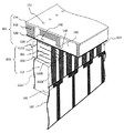
本発明にかかる記録ヘッド10は図1に示すように、インク流路ユニット101と、該ユニット101を保持するヘッドハウジング102と、圧電素子ユニット103とから構成される。このうち、インク流路ユニット101は、図2に示すようにノズル孔131が列状に設けられたオリフィス板130と、インク流路形成板142と、ダイアフラム120が形成されたダイアフラム形成板122を順に接着剤で貼り付けられるか、或いは陽極接合法等により接合することにより形成される。
(1)
As shown in FIG. 1, the
上記インク流路ユニット101により、ノズル孔131を開口端とするインク加圧室140、このインク加圧室140にインクを導くインク流入口145、このインク流入口145にインクを供給する共通インク室150が構成される。また、ダイアフラム形成板122の貼り付けにより、インク加圧室140の少なくとも一つの壁面はダイアフラム120で形成される。そして、ダイアフラム120のインク加圧室140と反対側の面には、圧電素子ユニット103の棒状圧電素子110の先端部が突き当てられ、接着剤によりダイアフラム120に接着されている。
By the ink
圧電素子ユニット103は複数の棒状圧電素子110を櫛歯状に圧電素子支持基板113に固着することにより構成される。棒状圧電素子110は、複数の層状圧電素子111が層状電極112を介して積層された構造を有する。層状電極112は1つおきに棒状圧電素子110の側面に形成された共通電極1121と個別電極1122に接続される。そして、共通電極1121と個別電極1121は圧電素子支持基板113の上面に形成された共通電極1121’と個別電極1122’にそれぞれ接続される。更に個別電極1121’は2個を1組にしてフレキシブルケーブル160のフレキシブルケーブル端子161に接続される。
The
上記圧電素子110の配列方向の両端に位置する圧電素子支持基板113には、図1に示すように柱状の圧電素子支持基板固定部114が設けられて、該固定部114の底面がインク流路ユニット101に接着剤等により固定されている。一方、インク流路ユニット101は、前記接着固定部の近傍でヘッドハウジング102に接着固定されているため、圧電素子支持基板固定部114の底面がヘッドハウジング102に対して固定されていることになる。
As shown in FIG. 1, columnar piezoelectric element support
上記のように構成された記録ヘッド10において、オリフィス板130には図3−1に示すように、所定ピッチで列状にn個のノズル孔131が形成され、このノズル孔131を開口端とするインク加圧室140及び櫛歯状の棒状圧電素子110によりn個のノズル素子(#1、#2、…n)が形成される。各ノズル素子からは30で示されるインク液滴が吐出され、記録媒体40に記録される。
In the
本発明においては隣接する2つの棒状圧電素子110が互いに逆極性に分極され、且つ分極の大きさが略同一になるように予め設定されている。
In the present invention, two adjacent rod-shaped
従って、図3−1の第1番目のノズル素子#1と第2番目のノズル素子#2についてみた場合、ノズル素子#1の共通電極1121と個別電極1122との間の圧電素子には図示の方向に分極が残留しており、一方、ノズル素子#2の共通電極1121と個別電極1122との間には図のように逆方向でノズル素子#1と略同じ大きさの分極が残留しているため、両素子#1、#2に同じ電圧が印加された際、ノズル素子#1とノズル素子#2も圧電素子は、互いに反対方向に略同一量変位する。
Accordingly, when the first
(2)記録ヘッド駆動装置20
記録ヘッド駆動装置20は、図1に示すように記録データ信号作成回路302、圧電素子駆動データ信号作成回路303、圧電素子駆動スイッチング回路304、タイミング信号発生回路301、A&B相圧電素子駆動パルス波形発生回路305を備える。
(2) Recording head driving device 20
As shown in FIG. 1, the recording head driving device 20 includes a recording data signal generating
記録データ信号作成回路302は、図示しない上位装置(例えば、パーソナルコンピュータ)から送られてくる記録信号入力データに基づいて、記録データ信号を作成する。圧電素子駆動データ信号作成回路303は記録データ信号とタイミング信号発生回路301からのタイミング信号をもとに、圧電素子駆動データ信号を作成する。
The recording data signal
圧電素子駆動データ信号作成回路303は、記録ヘッドの奇数番目のノズルを駆動するための奇数番ノズル用圧電素子駆動データ信号回路と、偶数番目のノズルを駆動するための偶数番ノズル用圧電素子駆動データ信号回路を備える。また、隣接する奇数番目のノズル素子と、偶数番目のノズル素子は2個毎に順次グルーピングされ、各グループの2つの圧電素子110は、圧電素子駆動スイッチング回路304の一個のスイッチング素子に共通に接続される。
The piezoelectric element drive data
即ち図3−1に示すように、第1番目のノズル素子#1と第2番目のノズル素子#2を1組として、それぞれの圧電素子110の個別電極1122が圧電素子駆動スイッチング回路304のスイッチSW1に接続される。そして第3番目のノズル素子#3と第4番目のノズル素子#4を1組として、それぞれの圧電素子110の個別電極1122かスイッチSW2に接続される。以下同様にして隣接する2個のノズル素子が1組としてその組に属する圧電素子110の個別電極1122が別々のスイッチに接続される。また全てのノズル素子#1、#2、#3…#nの圧電素子110の共通電極1121は共通に接続される。
That is, as shown in FIG. 3A, the first
一方、A&B相圧電素子駆動パルス波形発生回路305は、図4の(a)に示すようなA位相駆動パルス及びB位相駆動パルスを発生し、このパルスが共通電極1121を介して圧電素子110に印加される。スイッチング素子SW1,SW2は、圧電素子駆動データ信号で制御されるスイッチング素子駆動回路3042により作動し、例えばスイッチSW1がオンすると隣接する2つのノズル素子#1と#2の圧電素子110にはA相及びB相の圧電素子駆動パルスが同時に印加される。
On the other hand, the A & B phase piezoelectric element drive pulse
(3)インク滴吐出動作
次に本発明にかかるインクジェット記録装置のインク滴吐出動作を図3−1,3−2,3−3及び図4を用いて説明する。
(3) Ink Drop Discharge Operation Next, the ink drop discharge operation of the ink jet recording apparatus according to the present invention will be described with reference to FIGS. 3-1, 3-2, 3-3 and FIG.
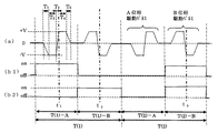
図4(a)はA&B相圧電素子駆動パルス波形発生回路305の出力、(b1)はスイッチング素子SW1の駆動パルス、(b2)はスイッチング素子SW2の駆動パルスの各波形を示す。
4A shows the output of the A & B phase piezoelectric element drive pulse
圧電素子110を駆動するためのパルスはA位相駆動パルスとB位相駆動パルスとからなる。A位相は電圧が期間T1において0レベルから−Vに変化し、−Vを所定時間T2維持した後、期間T3において−Vから+Vに上昇し、+Vを所定時間T4維持した後、期間T5において+Vから0レベルに戻る波形である。B位相はA位相とは逆に最初T1の時間に0レベルから+Vに上昇し、+Vを所定時間T2維持した後、期間T3において+Vから−Vに変化し、−Vを所定時間T4維持した後期間T5において−Vから0レベルに戻る波形である。
A pulse for driving the
また(b1)及び(b2)の駆動パルスのレベルが高のとき、それぞれスイッチSW1及びSW2がオンし、駆動パルスのレベルが低のとき、それぞれスイッチSW1及びSW2はオフするように駆動される。 When the drive pulse level of (b1) and (b2) is high, the switches SW1 and SW2 are turned on, and when the drive pulse level is low, the switches SW1 and SW2 are driven to turn off.
図4において、T(1)−Aの時間には(b1)の信号によりスイッチング素子SW1がオン、(b2)の信号によりスイッチング素子SW2がオフに制御されるため、図3−1のようにSW1の接点は閉じSW2の接点は開く。従って、スイッチング素子SW1を介してノズル素子#1とノズル素子#2の圧電素子110の個別電極1122が接地される。
In FIG. 4, since the switching element SW1 is controlled to be turned on by the signal (b1) and the switching element SW2 is turned off by the signal (b2) at time T (1) -A, as shown in FIG. The contact of SW1 is closed and the contact of SW2 is opened. Therefore, the
一方、圧電素子110の共通電極1121には図4(a)に示す駆動パルス電圧が印加されているので、ノズル素子#1とノズル素子#2はA位相駆動パルス電圧で駆動されることになる。
On the other hand, since the drive pulse voltage shown in FIG. 4A is applied to the
このためノズル素子#1の圧電素子110は期間T1において次第に縮み、期間T2において縮んだ状態を保ち、期間T3で急激に伸び、期間T4では伸びた状態を保ち、期間T5では次第に元の状態に戻る。このような圧電素子の伸縮運動により、インク加圧室140の体積が変化する。
For this reason, the
図3−1におけるノズル素子#1は時刻t1の状態、つまり圧縮素子110が急激に伸びた状態を示す。この圧電素子110の伸長及びインク加圧室の体積収縮により、インク滴30がノズル素子#1のノズル孔131から吐出される。これに対してノズル素子#2の圧電素子110は、その分極の方向がノズル素子#1の圧電素子110とはとは逆で、分極の大きさが略同程度に設定してあるので、ノズル素子#2の圧電素子110及びインク加圧室140の伸縮運動はノズル素子#1とは全く逆になる。よって期間T3では加圧室140の体積は増加し、インクが共通インク室150からインク流入口145を通ってインク加圧室140に供給されることになる。
このため図4(a)のA位相駆動パルスが印加されてもノズル素子#2のノズル孔131からインク滴が吐出されることはない。逆にメニスカスがノズル孔131からインク加圧室140側に引き込まれるが、インク流入口145を大きめに設定すること等で、ノズル孔131からインク加圧室140への気泡吸い込みは防止できる。またノズル素子#3、#4は、SW2がオフであるので、図4(a)の駆動パルス電圧が印加されることはなく圧電素子110は伸縮せず停止したままである。
For this reason, even if the A phase driving pulse of FIG. 4A is applied, no ink droplet is ejected from the
次に、T(1)−Bの期間には図4(b1)の信号によりスイッチング素子SW1がオフになり、図4(b2)の信号によりSW2がオンに制御される。従って図3−2に示すようにスイッチング素子SW1の接点は開き、SW2の接点が閉じる。このためスイッチング素子SW2を介してノズル素子#3とノズル素子#4の圧電素子110の個別電極1122が接地される。
Next, in the period T (1) -B, the switching element SW1 is turned off by the signal in FIG. 4B1, and SW2 is controlled to be turned on by the signal in FIG. 4B2. Therefore, as shown in FIG. 3-2, the contact of the switching element SW1 is opened, and the contact of SW2 is closed. For this reason, the
圧電素子110の共通電極1121には、図4(a)の駆動パルス電圧が印加されているので、ノズル素子#3とノズル素子#4はB位相駆動パルスで駆動されることになる。このためノズル素子#4の圧電素子110は時刻t2において伸長し、インク加圧室140の体積は収縮状態になるため、インク滴30が吐出される。一方ノズル素子#3の圧電素子110は逆方向に分極するため時刻t2においてインク加圧室140の体積が増加し、共通インク室150からのインクがインク加圧室140に吸い込んだ状態になるのでインク滴は吐出しない。また、スイッチング素子SW1はオフであるため、ノズル素子#1、#2の圧電素子110に駆動パルス電圧が印加されることはなく、停止のままになる。
Since the drive pulse voltage shown in FIG. 4A is applied to the
次に図4のT(2)−Aの期間においてはスイッチング素子SW1、SW2が共にオフであるため、ノズル素子#1、#2は引き続き停止のままであり、ノズル素子#3、#4も停止となる。
Next, in the period T (2) -A in FIG. 4, since the switching elements SW1 and SW2 are both off, the
T(2)−Bの期間においては、スイッチング素子SW1、SW2が共にオンである。したがってノズル素子#1〜4に、B位相駆動パルス電圧が印加され、時刻t3において圧電素子110及びインク加圧室140は図3−3のような伸縮状態となる。従って、ノズル素子#2、#4からインク滴が吐出するように制御される。
In the period of T (2) -B, both the switching elements SW1 and SW2 are on. Therefore, the B-phase driving pulse voltage is applied to the
以上4個のノズル素子#1〜#4の動作について説明したが、ノズル素子の数が増加しても同様の制御が可能である。即ち、多数ノズル素子の中の所望のノズル素子からインク滴を吐出するには、そのノズル素子に接続されたスイッチング素子を、当該ノズル素子が奇数番目の時には、A位相駆動パルスで駆動すればよい。また、当該ノズル素子が偶数番目のノズルの場合には、B位相駆動パルスで駆動すればよい。隣接する奇数ノズル素子と偶数ノズル素子から同時にインク滴を吐出することはできないが、奇数ノズル素子が記録する記録データと、偶数ノズル素子が記録する記録データを、A位相駆動パルスとB位相駆動パルスの時間差をもとにずらすことで対応可能である。
Although the operation of the four
以上述べたように、本発明にかかるインクジェット記録装置は、記録ヘッドを構成する多数のノズル素子が、隣接する2個のノズル素子毎にグルーピングされると共に、隣接する2個のノズル素子は、分極極性が逆で、且つ、分極の大きさが略同じ圧電素子を有し、各圧電素子が同一波形の駆動パルス電圧で駆動されるように構成されているため、これら2個のノズル素子におけるダイアフラムの振動、圧電素子支持基板への加振状態、各部の変位等は完全に逆になる。このため、これら隣接する2個のノズル素子の圧電振動子が駆動されたとき、他の部位への加振力、即ち他のノズル素子や圧電素子支持基板、ハウジング等の共通部材への加振力が抑制されるため、圧電振動子の駆動による異常振動が抑制される。従って、本発明によればメニスカスの異常振動が無くなり、クロストークも減少し安定なインク滴の吐出が可能になる。 As described above, in the ink jet recording apparatus according to the present invention, a large number of nozzle elements constituting a recording head are grouped for every two adjacent nozzle elements, and the two adjacent nozzle elements are polarized. Since the piezoelectric elements having the opposite polarities and the polarization magnitudes are substantially the same, and each piezoelectric element is driven by the drive pulse voltage having the same waveform, the diaphragm in these two nozzle elements The vibration of the piezoelectric element, the state of vibration applied to the piezoelectric element support substrate, the displacement of each part, etc. are completely reversed. For this reason, when the piezoelectric vibrators of these two adjacent nozzle elements are driven, the excitation force to other parts, that is, the excitation to a common member such as another nozzle element, piezoelectric element support substrate, housing, etc. Since the force is suppressed, abnormal vibration due to driving of the piezoelectric vibrator is suppressed. Therefore, according to the present invention, abnormal vibration of the meniscus is eliminated, crosstalk is reduced, and stable ink droplet ejection is possible.
また、本発明によれば、隣接する2個のノズル素子が1個のスイッチング素子に接続されるため、スイッチング素子の数が従来に比べて半減し、また記録ヘッドと記録ヘッド駆動装置間を接続するケーブルの配線本数も半減する。よって記録装置の低価格化、小型化にも有利である。 In addition, according to the present invention, since two adjacent nozzle elements are connected to one switching element, the number of switching elements is halved compared to the prior art, and the recording head and the recording head driving device are connected. The number of cables to be used is also halved. Therefore, it is advantageous for reducing the cost and size of the recording apparatus.
なお以上の実施例は圧電素子110の分極1123の方向が隣接するノズルで逆方向となるように構成された例であるが、図3−4に示すように圧電素子110の分極1123の方向を、各ノズルに付いて全て同じとし、共通電極1121も個別電極1122と同構造に、ノズルごとに独立した構成としてもよい。この場合は、第一の圧電素子の共通電極1121と第二の圧電素子の個別電極1122が結線Aで接続され、また、第一の圧電素子の個別電極1122と第二の圧電素子の共通電極1121が結線Bで接続される。結線Aは、各ペアーノズル間で束ねられ、A&B相圧電素子駆動パルス波形発生回路305に接続され、結線Bは、各ペアーノズルごとにスイッチング素子3041に接続されている。
The above embodiment is an example in which the direction of the
この構成により、第一の圧電素子と、第二の圧電素子には、分極極性に対して、互いに逆の駆動電圧が印加されるので、ダイヤフラムヘの振動を逆方向になるように動作させることが可能である。 With this configuration, since the drive voltages opposite to each other are applied to the first piezoelectric element and the second piezoelectric element with respect to the polarization polarity, the vibration to the diaphragm is operated in the opposite direction. Is possible.
この実施例によれば、共通電極をノズルごとに独立させる必要があるが、図3−1〜図3−3の実施例のように第一の圧電素子と第二の圧電素子の分極方向を逆にする必要はなく、本発明を実施することが可能である。 According to this embodiment, it is necessary to make the common electrode independent for each nozzle, but the polarization directions of the first piezoelectric element and the second piezoelectric element are changed as in the embodiments of FIGS. There is no need to reverse, and the present invention can be implemented.
(4)記録ヘッドの他の実施例
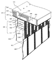
図5は本発明にかかる記録ヘッドの第2の実施例を示す概略構成図である。この実施例では、隣接する2個のノズル素子が、スイッチング素子を共有できるようにするために、2個のノズル素子の個別電極1122が、圧電素子支持基板113の面上の配線で接続されている。図2に示す第1の実施例に比べ、圧電素子支持基板113の面上に形成される個別電極1122’の面積が広くなるので、フレキシブルケーブル160のケーブル端子161と個別電極1122’との接続が容易になる。
(4) Another Embodiment of Recording Head FIG. 5 is a schematic configuration diagram showing a second embodiment of the recording head according to the present invention. In this embodiment, in order to allow two adjacent nozzle elements to share a switching element, the
尚、隣接する2個のノズル素子がスイッチング素子を共有するために、2つの配線を圧電素子駆動スイッチング回路基板上で結線してもよい。この場合は、フレキシブルケーブル160の配線本数は従来と同じであるが、スイッチング素子の数は半減することができる。
Note that, since two adjacent nozzle elements share a switching element, two wires may be connected on the piezoelectric element drive switching circuit board. In this case, the number of wirings of the
図6は本発明にかかる記録ヘッドの第3の実施例を示す概略構成図である。この実施例では、インク流入口145の大きさを、共通インク室150からインク加圧室140に向かう方向に徐々に小さくなるような形状に構成されている。即ち図2に示す実施例に比べて共通インク室150からインク加圧室140に向かう方向に流路を絞った形状にし、流体ダイオード特性を持たせている。
FIG. 6 is a schematic configuration diagram showing a third embodiment of the recording head according to the present invention. In this embodiment, the size of the
このように構成すると隣接する2個のノズル素子が同一の駆動パルスで駆動された場合、インク滴を吐出しない側のノズル素子のインク加圧室の体積が増大し、共通インク室からインクが流れ込んだとき、メニスカスのインク加圧室側への移動を抑制することができる。このため、ノズル孔からの空気吸い込みを防止したりインク吐出の周波数応答特性の低下を防止することができる。 With this configuration, when two adjacent nozzle elements are driven with the same drive pulse, the volume of the ink pressurization chamber of the nozzle element on the side that does not eject ink droplets increases, and ink flows from the common ink chamber. At this time, the movement of the meniscus toward the ink pressurizing chamber can be suppressed. For this reason, it is possible to prevent air from being sucked from the nozzle holes and to prevent a decrease in frequency response characteristics of ink discharge.
また本実施例では、オリフィス板130の表面のノズル孔131の周囲に凹部状のインク溜め132が形成されている。これにより、ノズル孔周辺インク溜め132中に溜まったインクがインク加圧室側140に移動可能になるため、メニスカスのインク加圧室140側への移動に伴う悪影響を更に効果的に防止することができる。
In this embodiment, a
以上説明した本発明にかかる記録ヘッドは、シリアル走査型インクジェット記録装置やライン走査型インクジェット記録装置に好適である。シリアル走査型インクジェット記録装置に、本発明記録ヘッドを用いる場合は、オリフィス板130の面を記録用紙に対向させて設置し、該記録ヘッドを長手記録用紙の連続方向と交叉する横方向に、インク滴を記録信号に応じて吐出しながら移動(主走査)させて一行分を記録し、その後、長手記録用紙の連続方向に、記録用紙を所定量紙送り(副走査)し、続いて次の行の画像を主走査して記録する。この主走査と副走査を繰り返して画像を記録する。
The recording head according to the present invention described above is suitable for a serial scanning ink jet recording apparatus and a line scanning ink jet recording apparatus. When the recording head of the present invention is used in a serial scanning type ink jet recording apparatus, the
また本発明記録ヘッドを、ライン走査型インクジェット記録装置に用いる場合は、多数の記録ヘッドを、連続記録用紙の幅方向に、幅いっぱいに記録用紙面に対向して配置し、インク滴を記録信号に応じて噴射する。同時に記録用紙を、連続記録用紙の長手方向に高速移動させて主走査する。この主走査とインク滴の吐出制御で走査線への記録ドット形成の制御を行い、記録画像を記録用紙上に得る。このような本発明によるインクジェット記録装置によれば、高品位画像を高速で印刷することが可能になる。 When the recording head of the present invention is used in a line scanning ink jet recording apparatus, a large number of recording heads are arranged in the width direction of the continuous recording paper so as to face the recording paper surface to the full width, and ink droplets are recorded on the recording signal. Depending on the spray. At the same time, the recording sheet is moved in the longitudinal direction of the continuous recording sheet at a high speed to perform main scanning. With this main scanning and ink droplet ejection control, recording dot formation on the scanning line is controlled to obtain a recorded image on the recording paper. According to such an ink jet recording apparatus according to the present invention, a high-quality image can be printed at high speed.
本発明は、記録用紙にインクで記録するインクジェット記録装置の用途の他に、生産物へのマーキング装置や塗膜装置等の工業用液体分配装置にも適用可能である。 The present invention can be applied to an industrial liquid dispensing apparatus such as a marking apparatus for a product and a coating film apparatus in addition to the use of an ink jet recording apparatus that records ink on recording paper.
10:記録ヘッド
20:記録ヘッド駆動装置
30:インク滴
40:記録媒体
101:インク流路ユニット
102:ヘッドハウジング
103:圧電素子ユニット
110:圧電素子
111:層状圧電素子
112:層状電極
1121:共通電極
1122:個別電極
1123:分極
113:圧電素子支持基板
114:圧電素子支持基板固定部
120:ダイアフラム
122:ダイアフラム形成板
130:オリフィス板
131:ノズル孔
140:インク加圧室
142:インク流路形成板
145:インク流入口
150:共通インク室
160:フレキシブルケーブル
161:フレキシブルケーブル端子
301:タイミング信号発生回路
302:記録データ信号作成回路
303:圧電素子駆動データ信号作成回路
304:圧電素子駆動スイッチング回路
3041,SW1,SW2:スイッチング素子
3042:スイッチング素子駆動回路
305:A&B相圧電素子駆動パルス波形発生回路
10: recording head 20: recording head driving device 30: ink droplet 40: recording medium 101: ink flow path unit 102: head housing 103: piezoelectric element unit 110: piezoelectric element 111: layered piezoelectric element 112: layered electrode 1121: common electrode 1122: Individual electrode 1123: Polarization 113: Piezoelectric element support substrate 114: Piezoelectric element support substrate fixing part 120: Diaphragm 122: Diaphragm forming plate 130: Orifice plate 131: Nozzle hole 140: Ink pressurizing chamber 142: Ink flow channel forming plate 145: ink inlet 150: common ink chamber 160: flexible cable 161: flexible cable terminal 301: timing signal generating circuit 302: recording data signal generating circuit 303: piezoelectric element driving data signal generating circuit 304: piezoelectric element driving
Claims (10)
隣接する第1及び第2のノズル素子は、前記第1のノズル素子のダイアフラムの振動と、前記第2のノズル素子のダイアフラムの振動が逆方向となるように、当該第1及び第2のノズル素子の圧電素子に駆動信号が印加されるものであって、
前記駆動信号を発生する駆動信号源は、負のパルスの次に正のパルスを発生するA位相駆動パルスと、正のパルスの次に負のパルスを発生するB位相駆動パルスを発生させる信号源よりなり、前記第1及び第2のノズル素子の圧電素子に、前記A位相駆動パルスを印加したときには第1のノズル素子よりインク液を吐出し、B位相駆動パルスを印加したときには第2のノズル素子よりインク液を吐出させるようにした
ことを特徴とするインクジェット記録ヘッド。 A plurality of nozzle elements arranged to eject ink liquid from the nozzle holes by attaching a piezoelectric element to a diaphragm forming a part of the ink pressurizing chamber and deforming the diaphragm according to the expansion and contraction of the piezoelectric element. In the inkjet recording head formed,
The first and second nozzle elements adjacent the diaphragm and the vibration of the front Symbol first nozzle element, vibration of the diaphragm of the second nozzle element is such that the opposite direction, the first and second A drive signal is applied to the piezoelectric element of the nozzle element,
The drive signal source for generating the drive signal is a signal source for generating an A phase drive pulse for generating a positive pulse next to a negative pulse and a B phase drive pulse for generating a negative pulse next to the positive pulse. When the A phase driving pulse is applied to the piezoelectric elements of the first and second nozzle elements, the ink liquid is ejected from the first nozzle element, and when the B phase driving pulse is applied, the second nozzle An ink jet recording head, wherein an ink liquid is ejected from an element .
Priority Applications (1)
| Application Number | Priority Date | Filing Date | Title |
|---|---|---|---|
| JP2005364527A JP4756225B2 (en) | 2004-12-20 | 2005-12-19 | RECORDING HEAD AND INKJET RECORDING DEVICE HAVING THE SAME |
Applications Claiming Priority (3)
| Application Number | Priority Date | Filing Date | Title |
|---|---|---|---|
| JP2004367238 | 2004-12-20 | ||
| JP2004367238 | 2004-12-20 | ||
| JP2005364527A JP4756225B2 (en) | 2004-12-20 | 2005-12-19 | RECORDING HEAD AND INKJET RECORDING DEVICE HAVING THE SAME |
Publications (3)
| Publication Number | Publication Date |
|---|---|
| JP2006199030A JP2006199030A (en) | 2006-08-03 |
| JP2006199030A5 JP2006199030A5 (en) | 2009-01-08 |
| JP4756225B2 true JP4756225B2 (en) | 2011-08-24 |
Family
ID=36957431
Family Applications (1)
| Application Number | Title | Priority Date | Filing Date |
|---|---|---|---|
| JP2005364527A Expired - Fee Related JP4756225B2 (en) | 2004-12-20 | 2005-12-19 | RECORDING HEAD AND INKJET RECORDING DEVICE HAVING THE SAME |
Country Status (1)
| Country | Link |
|---|---|
| JP (1) | JP4756225B2 (en) |
Families Citing this family (2)
| Publication number | Priority date | Publication date | Assignee | Title |
|---|---|---|---|---|
| JP5147770B2 (en) * | 2009-03-26 | 2013-02-20 | 富士フイルム株式会社 | Droplet discharge head and image forming apparatus |
| KR102338163B1 (en) * | 2019-08-14 | 2021-12-13 | 에이피시스템 주식회사 | Nozzle module for dispenser, dispenser, and dispensing method using the same |
Family Cites Families (5)
| Publication number | Priority date | Publication date | Assignee | Title |
|---|---|---|---|---|
| JPH07164640A (en) * | 1993-12-15 | 1995-06-27 | Ricoh Co Ltd | Ink jet recorder |
| JPH0825630A (en) * | 1994-07-20 | 1996-01-30 | Ricoh Co Ltd | Ink jet head |
| DE69616665T2 (en) * | 1995-07-03 | 2002-08-01 | Oce Tech Bv | Inkjet printhead |
| JPH11334069A (en) * | 1998-05-27 | 1999-12-07 | Oki Data Corp | Ink jet head |
| JP2000043266A (en) * | 1998-07-24 | 2000-02-15 | Samsung Electro Mech Co Ltd | Ink jet printer head |
-
2005
- 2005-12-19 JP JP2005364527A patent/JP4756225B2/en not_active Expired - Fee Related
Also Published As
| Publication number | Publication date |
|---|---|
| JP2006199030A (en) | 2006-08-03 |
Similar Documents
| Publication | Publication Date | Title |
|---|---|---|
| JP3772805B2 (en) | Liquid ejecting head and liquid ejecting apparatus including the same | |
| JP4251912B2 (en) | Image forming apparatus | |
| US7651203B2 (en) | Inkjet recording device, ejecting device provided therein, and method of calibrating ejection characteristic for droplet | |
| JP3419401B2 (en) | Method of manufacturing ink jet recording head and ink jet recording head | |
| JP2007015127A (en) | Liquid jet device | |
| JP4687442B2 (en) | Liquid ejector | |
| US7478898B2 (en) | Recording head for inkjet recording device | |
| US10160214B2 (en) | Liquid ejecting apparatus | |
| JP4237382B2 (en) | Inkjet head drive device | |
| JP4756225B2 (en) | RECORDING HEAD AND INKJET RECORDING DEVICE HAVING THE SAME | |
| JP6063108B2 (en) | Liquid ejecting apparatus and control method thereof | |
| JP2010105300A (en) | Liquid discharge apparatus | |
| JP4296796B2 (en) | Liquid ejecting apparatus and droplet ejection control method thereof | |
| JP2000218787A (en) | Ink-jet recording head and image recording apparatus | |
| JP2004042414A (en) | Driving method for ink jet head, and ink jet printer using the driving method | |
| JP6471797B2 (en) | Liquid ejector | |
| JP4412950B2 (en) | Image forming apparatus | |
| JP2003118107A (en) | Liquid jet apparatus, driving method for the apparatus, and computer readable recording medium | |
| JP2020055213A (en) | Liquid discharge head | |
| JP7122051B1 (en) | How to drive the print head | |
| JP2007283706A (en) | Driving device of droplet discharge head and driving method of droplet discharge head | |
| US8702188B2 (en) | Device and method for driving liquid-drop ejection head and image forming apparatus | |
| JP2011031441A (en) | Inkjet recorder | |
| JP4541856B2 (en) | Driving method of piezoelectric ink jet head | |
| JP2023034638A (en) | Liquid ejection device |
Legal Events
| Date | Code | Title | Description |
|---|---|---|---|
| A521 | Written amendment |
Free format text: JAPANESE INTERMEDIATE CODE: A523 Effective date: 20081113 |
|
| A621 | Written request for application examination |
Free format text: JAPANESE INTERMEDIATE CODE: A621 Effective date: 20081113 |
|
| A977 | Report on retrieval |
Free format text: JAPANESE INTERMEDIATE CODE: A971007 Effective date: 20110209 |
|
| A131 | Notification of reasons for refusal |
Free format text: JAPANESE INTERMEDIATE CODE: A131 Effective date: 20110214 |
|
| A521 | Written amendment |
Free format text: JAPANESE INTERMEDIATE CODE: A523 Effective date: 20110408 |
|
| TRDD | Decision of grant or rejection written | ||
| A01 | Written decision to grant a patent or to grant a registration (utility model) |
Free format text: JAPANESE INTERMEDIATE CODE: A01 Effective date: 20110502 |
|
| A61 | First payment of annual fees (during grant procedure) |
Free format text: JAPANESE INTERMEDIATE CODE: A61 Effective date: 20110515 |
|
| R150 | Certificate of patent or registration of utility model |
Ref document number: 4756225 Country of ref document: JP Free format text: JAPANESE INTERMEDIATE CODE: R150 Free format text: JAPANESE INTERMEDIATE CODE: R150 |
|
| FPAY | Renewal fee payment (event date is renewal date of database) |
Free format text: PAYMENT UNTIL: 20140610 Year of fee payment: 3 |
|
| S111 | Request for change of ownership or part of ownership |
Free format text: JAPANESE INTERMEDIATE CODE: R313113 |
|
| FPAY | Renewal fee payment (event date is renewal date of database) |
Free format text: PAYMENT UNTIL: 20140610 Year of fee payment: 3 |
|
| R350 | Written notification of registration of transfer |
Free format text: JAPANESE INTERMEDIATE CODE: R350 |
|
| LAPS | Cancellation because of no payment of annual fees |