JP4755381B2 - Check valve for piston pump - Google Patents
Check valve for piston pump Download PDFInfo
- Publication number
- JP4755381B2 JP4755381B2 JP2001582721A JP2001582721A JP4755381B2 JP 4755381 B2 JP4755381 B2 JP 4755381B2 JP 2001582721 A JP2001582721 A JP 2001582721A JP 2001582721 A JP2001582721 A JP 2001582721A JP 4755381 B2 JP4755381 B2 JP 4755381B2
- Authority
- JP
- Japan
- Prior art keywords
- valve
- check valve
- piston
- pump
- valve seat
- Prior art date
- Legal status (The legal status is an assumption and is not a legal conclusion. Google has not performed a legal analysis and makes no representation as to the accuracy of the status listed.)
- Expired - Fee Related
Links
Images

Classifications
-
- B—PERFORMING OPERATIONS; TRANSPORTING
- B60—VEHICLES IN GENERAL
- B60T—VEHICLE BRAKE CONTROL SYSTEMS OR PARTS THEREOF; BRAKE CONTROL SYSTEMS OR PARTS THEREOF, IN GENERAL; ARRANGEMENT OF BRAKING ELEMENTS ON VEHICLES IN GENERAL; PORTABLE DEVICES FOR PREVENTING UNWANTED MOVEMENT OF VEHICLES; VEHICLE MODIFICATIONS TO FACILITATE COOLING OF BRAKES
- B60T8/00—Arrangements for adjusting wheel-braking force to meet varying vehicular or ground-surface conditions, e.g. limiting or varying distribution of braking force
- B60T8/32—Arrangements for adjusting wheel-braking force to meet varying vehicular or ground-surface conditions, e.g. limiting or varying distribution of braking force responsive to a speed condition, e.g. acceleration or deceleration
- B60T8/34—Arrangements for adjusting wheel-braking force to meet varying vehicular or ground-surface conditions, e.g. limiting or varying distribution of braking force responsive to a speed condition, e.g. acceleration or deceleration having a fluid pressure regulator responsive to a speed condition
- B60T8/40—Arrangements for adjusting wheel-braking force to meet varying vehicular or ground-surface conditions, e.g. limiting or varying distribution of braking force responsive to a speed condition, e.g. acceleration or deceleration having a fluid pressure regulator responsive to a speed condition comprising an additional fluid circuit including fluid pressurising means for modifying the pressure of the braking fluid, e.g. including wheel driven pumps for detecting a speed condition, or pumps which are controlled by means independent of the braking system
- B60T8/4031—Pump units characterised by their construction or mounting
-
- F—MECHANICAL ENGINEERING; LIGHTING; HEATING; WEAPONS; BLASTING
- F04—POSITIVE - DISPLACEMENT MACHINES FOR LIQUIDS; PUMPS FOR LIQUIDS OR ELASTIC FLUIDS
- F04B—POSITIVE-DISPLACEMENT MACHINES FOR LIQUIDS; PUMPS
- F04B53/00—Component parts, details or accessories not provided for in, or of interest apart from, groups F04B1/00 - F04B23/00 or F04B39/00 - F04B47/00
- F04B53/10—Valves; Arrangement of valves
- F04B53/102—Disc valves
- F04B53/1022—Disc valves having means for guiding the closure member axially
-
- F—MECHANICAL ENGINEERING; LIGHTING; HEATING; WEAPONS; BLASTING
- F04—POSITIVE - DISPLACEMENT MACHINES FOR LIQUIDS; PUMPS FOR LIQUIDS OR ELASTIC FLUIDS
- F04B—POSITIVE-DISPLACEMENT MACHINES FOR LIQUIDS; PUMPS
- F04B53/00—Component parts, details or accessories not provided for in, or of interest apart from, groups F04B1/00 - F04B23/00 or F04B39/00 - F04B47/00
- F04B53/10—Valves; Arrangement of valves
- F04B53/102—Disc valves
- F04B53/1032—Spring-actuated disc valves
-
- F—MECHANICAL ENGINEERING; LIGHTING; HEATING; WEAPONS; BLASTING
- F04—POSITIVE - DISPLACEMENT MACHINES FOR LIQUIDS; PUMPS FOR LIQUIDS OR ELASTIC FLUIDS
- F04B—POSITIVE-DISPLACEMENT MACHINES FOR LIQUIDS; PUMPS
- F04B53/00—Component parts, details or accessories not provided for in, or of interest apart from, groups F04B1/00 - F04B23/00 or F04B39/00 - F04B47/00
- F04B53/10—Valves; Arrangement of valves
- F04B53/12—Valves; Arrangement of valves arranged in or on pistons
- F04B53/125—Reciprocating valves
- F04B53/127—Disc valves
-
- F—MECHANICAL ENGINEERING; LIGHTING; HEATING; WEAPONS; BLASTING
- F16—ENGINEERING ELEMENTS AND UNITS; GENERAL MEASURES FOR PRODUCING AND MAINTAINING EFFECTIVE FUNCTIONING OF MACHINES OR INSTALLATIONS; THERMAL INSULATION IN GENERAL
- F16K—VALVES; TAPS; COCKS; ACTUATING-FLOATS; DEVICES FOR VENTING OR AERATING
- F16K15/00—Check valves
- F16K15/02—Check valves with guided rigid valve members
- F16K15/025—Check valves with guided rigid valve members the valve being loaded by a spring
- F16K15/026—Check valves with guided rigid valve members the valve being loaded by a spring the valve member being a movable body around which the medium flows when the valve is open
- F16K15/028—Check valves with guided rigid valve members the valve being loaded by a spring the valve member being a movable body around which the medium flows when the valve is open the valve member consisting only of a predominantly disc-shaped flat element
-
- F—MECHANICAL ENGINEERING; LIGHTING; HEATING; WEAPONS; BLASTING
- F16—ENGINEERING ELEMENTS AND UNITS; GENERAL MEASURES FOR PRODUCING AND MAINTAINING EFFECTIVE FUNCTIONING OF MACHINES OR INSTALLATIONS; THERMAL INSULATION IN GENERAL
- F16K—VALVES; TAPS; COCKS; ACTUATING-FLOATS; DEVICES FOR VENTING OR AERATING
- F16K15/00—Check valves
- F16K15/02—Check valves with guided rigid valve members
- F16K15/04—Check valves with guided rigid valve members shaped as balls
- F16K15/044—Check valves with guided rigid valve members shaped as balls spring-loaded
-
- Y—GENERAL TAGGING OF NEW TECHNOLOGICAL DEVELOPMENTS; GENERAL TAGGING OF CROSS-SECTIONAL TECHNOLOGIES SPANNING OVER SEVERAL SECTIONS OF THE IPC; TECHNICAL SUBJECTS COVERED BY FORMER USPC CROSS-REFERENCE ART COLLECTIONS [XRACs] AND DIGESTS
- Y10—TECHNICAL SUBJECTS COVERED BY FORMER USPC
- Y10T—TECHNICAL SUBJECTS COVERED BY FORMER US CLASSIFICATION
- Y10T137/00—Fluid handling
- Y10T137/7504—Removable valve head and seat unit
- Y10T137/7559—Pump type
-
- Y—GENERAL TAGGING OF NEW TECHNOLOGICAL DEVELOPMENTS; GENERAL TAGGING OF CROSS-SECTIONAL TECHNOLOGIES SPANNING OVER SEVERAL SECTIONS OF THE IPC; TECHNICAL SUBJECTS COVERED BY FORMER USPC CROSS-REFERENCE ART COLLECTIONS [XRACs] AND DIGESTS
- Y10—TECHNICAL SUBJECTS COVERED BY FORMER USPC
- Y10T—TECHNICAL SUBJECTS COVERED BY FORMER US CLASSIFICATION
- Y10T137/00—Fluid handling
- Y10T137/7722—Line condition change responsive valves
- Y10T137/7837—Direct response valves [i.e., check valve type]
- Y10T137/7904—Reciprocating valves
- Y10T137/7922—Spring biased
- Y10T137/7929—Spring coaxial with valve
- Y10T137/7936—Spring guides valve head
Description
【0001】
従来の技術
本発明は、請求項1の上位概念部に記載されたピストンポンプ用の逆止弁に関する。この逆止弁は特に、スリップコントロール装置を有する液圧式の車両ブレーキ装置のピストンポンプにおいて使用するためのものである。
【0002】
このような逆止弁は例えばドイツ連邦共和国特許公開第4107979号明細書に基づいて公知である。この公知の逆止弁は、ピストンポンプのピストンの端面に配置されており、この場合ピストンポンプはブレーキ液を圧送するために、スリップコントロール装置を有する液圧式の車両ブレーキ装置内に設けられている。ピストンは軸方向孔を有しており、この軸方向孔の開口は、逆止弁の弁座を形成している。弁座に配置された球は、公知の逆止弁の弁閉鎖体を形成している。自体公知のように逆止弁の閉鎖時に、弁閉鎖体を形成する球はシール作用をもって弁座に接触し、逆止弁の開放時には弁座から持ち上げられる。
【0003】
この公知の逆止弁には、ピストンポンプの組立て時にその組立てが面倒であるという欠点があり、公知の逆止弁は、構成群として予め組み立てることができない。公知の逆止弁における別の欠点としては、弁閉鎖体用の案内を設けなくてはならないということが挙げられる。
【0004】
発明の利点
請求項1の特徴部に記載の本発明による逆止弁では、弁閉鎖ばねがU字形ばね部材として形成されており、該U字形ばね部材が弁閉鎖体に被さって係合していて、弁座体に固定されていて、しかも弁閉鎖体を弁座体と可動に結合している。本発明による逆止弁には次のような利点がある。すなわち本発明による逆止弁では、その弁閉鎖ばねが弁閉鎖体のための案内と弁行程制限体とを同時に形成している。弁閉鎖体の弁行程制限体を形成しているということは、U字形ばね部材が、弁閉鎖体が弁座から持ち上がることのできる距離を制限しているということを、意味する。このような弁行程制限体によって、逆止弁の閉鎖時間を短くすることができる。本発明による逆止弁は単に3つの部材から簡単かつ安価に製造可能であり、これは逆止弁を小型化するのに適しており、ひいてはスリップコントロールされた車両ブレーキ装置のピストンポンプの流入弁又は流出弁として使用するのに適している。しかしながらこれは、本発明による逆止弁の1つの使用可能性を示しているだけであり、本発明による逆止弁は、原則的に逆流を防止するために任意の箇所において使用することができる。本発明による逆止弁は、所属の部材もしくは部品が組み立てられていて、ユニットとしてストック可能であり、かつ組立て可能な構成群を形成している。
【0005】
請求項1に記載された本発明による逆止弁の別の有利な構成は、請求項2以下に記載されている。
【0006】
請求項3記載のように、弁閉鎖体を円板形の部材として形成すると、逆止弁が開放時に迅速に大きな貫流横断面を開放し、これによって逆止弁は良好な動力学的な特性を有する、という利点が得られる。
【0007】
本発明による逆止弁は、ピストンポンプの流入弁又は流出弁として、特にピストンポンプのピストンの端面に取り付けるように、設けられている。ピストンポンプは本発明によれば特に、車両のブレーキ装置内におけるポンプとして設けられており、ホイールブレーキシリンダにおける圧力を制御する場合に使用される。ブレーキ装置の形式に応じてこのようなブレーキ装置のためには、略語であるABS;ASR;FDR;EHBが使用される。ブレーキ装置においてポンプユニットは例えば1つ又は複数のホイールブレーキシリンダからマスタブレーキシリンダにブレーキ液を戻す(ABS)ため及び/又は蓄え容器から単数又は複数のホイールブレーキシリンダにブレーキ液を搬送する(ASR;FDR;EHB)ために働く。ポンプは例えば、ホイールスリップコントロール機能を備えたブレーキ装置(ABS;ASR)及び/又はステアリング補助として働くブレーキ装置(FDR)及び/又は電気液圧式のブレーキ装置(EHB)において必要である。ホイールスリップコントロール機能(ABS;ASR)によって、例えば、ブレーキペダルを強く踏み込んだ場合にブレーキ動作中に車両のホイールがロックすることを回避する(ABS)こと、及び/又はアクセルペダルを強く踏み込んだ場合に車両の駆動輪が暴走することを回避する(ASR)ことができる。ステアリング補助(FDR)として働くブレーキ装置では、ブレーキペダルもしくはアクセルペダルの操作とは無関係に、単数又は複数のホイールブレーキシリンダにおいてブレーキ圧が形成され、これによって例えばドライバが望むトレースから車両が外れることを阻止することができる。ポンプユニットはまた電気液圧式のブレーキ装置(EHB)においても使用することができる。このような電気液圧式のブレーキ装置では、電気式のブレーキペダルセンサがブレーキペダルの操作を検出した場合に、ポンプユニットはブレーキ液を単数又は複数のホイールブレーキシリンダに搬送するか、又はポンプユニットはブレーキ装置のアキュムレータを充填するために働く。
【0008】
図面
次に図面を参照しながら本発明の有利な実施例を説明する。
【0009】
図1は、本発明による逆止弁を備えたピストンポンプを示す断面図である。
【0010】
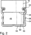
図2は、図1に示された逆止弁を拡大して示す側面図である。
【0011】
実施例の記載
図1に示されたピストンポンプ10は液圧ブロック12に挿入されており、この液圧ブロック12はポンプケーシングを形成しているので、以下においてはポンプケーシングと呼ぶ。図面には単にピストンポンプ10を取り囲む一部分だけが示されている液圧ブロック12は、一部だけが示されているスリップコントロールされる車両ブレーキ装置の液圧式の制御回路を内蔵している。液圧ブロック12内にはピストンポンプ10の他に、電磁弁のような別の構成エレメント(図示せず)が挿入されており、これらの構成エレメントは互いに液圧的に接続されている。
【0012】
ポンプケーシング12を形成する液圧ブロックは、段付けされたポンプ孔14を有しており、このポンプ孔14にはポット形のブシュ16が挿入されていて、このブシュ16は該ブシュと一体的なブシュ底部18を備えている。ブシュ16は深絞りによって金属薄板から製造されている。ピストンポンプ10のピストン20は、その全長の一部においてブシュ16内において軸方向シフト可能に案内されており、その全長の、ブシュ16から突出している他の部分においては、ポンプ孔14内において軸方向シフト可能に案内されている。ポンプ孔14及びブシュ16はピストンガイド14,16を形成している。
【0013】
ピストン20は主として2つの部分から成っており、カップ形の外側部分22を有していて、この外側部分22内にはポット形の内側部分24がその全長の約半分にわたってプレス嵌めされている。外側部分22及び内側部分24は深絞りによる変形部品として金属薄板から製造されている。内側部分24はリング段部26を有していて、このリング段部26で外側部分22のリング段部27に接触している。内側部分24は端面に、該内側部分24と一体的な端壁28を有している。同様に外側部分22は該外側部分22と一体的な端壁30を有している。内側部分24の開放側は外側部分22とは反対の側に位置している。内側部分24の端壁28は、ブレーキ液を貫流させるための中央孔32を備えている。耐摩耗性を高めるために外側部分22は少なくともその端壁30の領域において焼き入れ硬化されており、その他の加工は行われておらず、内側部分24及び外側部分22の表面仕上げ(Oberflaechenguete)で十分である。
【0014】
図1に示されたピストンポンプ10は段付きピストンポンプとして形成されている。すなわちピストン20はブシュ16内において、ブシュ16外部のポンプケーシング12におけるポンプ孔14におけるよりも、大きな直径で案内され、かつシールされている。段付きポンプとして形成されていることによって、ピストンポンプ10は、ピストン20を取り囲むリング室34をポンプ孔14もしくはブシュ16内に有している。このリング室34の容積は、ピストン20の往復行程運動中に変化し、ピストンポンプ10のピストン20の吐出行程中にもブレーキ液を吸い込む。
【0015】
ブシュ16の自由な縁部36は内方に向かって縁曲げされており、ピストン20をその外側部分22のリング段部27のところでブシュ16内に保持している。圧縮コイルばねとして形成されたピストン戻しばね38が、ブシュ16内に挿入されている。ピストン戻しばね38はブシュ底部18に支持されていて、ピストン20の内側部分24のリング段部27をピストン20の内部において押圧している。そしてピストン戻しばね38はピストン20を、電動モータによって回転駆動可能な偏心体39の周面に押し付けており、この偏心体39は、ブシュ16から突出したピストン20の端面上に配置されている。偏心体39の回転駆動によって、ピストン20は駆動されて軸方向で往復行程運動する。
【0016】
ブシュ16内に位置するピストン20の端部には、本発明による逆止弁40が設けられており、この逆止弁40は図2に拡大して示されている。逆止弁40は中空円筒形の弁座部分42を有しており、この弁座部分42で、ピストン20のカップ形の内側部分24内にプレス嵌めされている。これによって逆止弁40とピストン20との間にはクランプ嵌合部(Klemmpassung)44が形成されており、このクランプ嵌合部44は逆止弁40をピストン20の内側部分24内に保持している。本発明による逆止弁40の弁座部分42は、ブレーキ液を貫流させるための中央孔32を備えた、ピストン20の内側部分24の端壁28に接触している。弁座部分42の、端壁28とは反対側の端縁は、逆止弁40の弁座46を形成している。弁座部分42の弁座46の側には、逆止弁40の円筒形又は円板形の弁閉鎖体48が配置されている。弁座部分42及び弁閉鎖体48はプラスチック射出成形品として製造されている。
【0017】
弁閉鎖体48は、逆止弁40の弁閉鎖ばねを形成するU字形ばね部材50によって被さるように係合されている。U字形ばね部材50は金属薄板条片から曲げ加工されている。弁座部分42における固定のためにU字形ばね部材50の両端部は、直角に内方に向かって曲げられていて、係止エレメント52を形成しており、両係止エレメント52は弁座部分42の外周部における切欠きに係合している。弁閉鎖体48の外周部に沿って軸平行に延びる、U字形ばね部材50の脚54は、波形隆起部56を備えており、これによって脚54はその長手方向においてばね弾性的に延びることができる。付加的なばね弾性をU字形ばね部材50はそのヨーク58の弾性的な可撓性によって得ており、このヨーク58は弁閉鎖体48の、弁座部分42とは反対側の端面60を越えて延在している。
【0018】
U字形ばね部材50は弁閉鎖体48を弁座部分42に保持しかつ案内しており、逆止弁40の弁行程を、つまり弁閉鎖体48が弁座46から持ち上がることのできる距離を制限しており、そして弁閉鎖体48を小さな予負荷力で弁座46に押し付けているので、逆止弁40は基本状態においては閉鎖され、かつ僅かな圧力差において貫流方向に開放する。本発明による逆止弁40は、大きな流過横断面を迅速に開放し、このことはピストンポンプ10の吸込み特性にとって重要なことである(動力学)。
【0019】
ピストン20の内側部分24と弁座部分42との間におけるクランプ嵌合部44は次のことのために働く。すなわちこのクランプ嵌合部44によって、ブレーキ液が逆止弁40を迂回してポンプ室62からピストン20の外側部分22内に流れることが阻止される。さらに加えてクランプ嵌合部44は逆止弁40を、ピストンポンプ10の運転中のみならず、ピストンポンプ10の組立て中にもピストン20にしっかりと保持する。これによってピストンポンプ10の製造に関する手間もしくはコストは全体として減じられる。
【0020】
本発明による逆止弁40はピストンポンプ10の流入弁を形成している。ブレーキ液の流入のために、流入開口64がピストンポンプ10のピストン20の外側部分22の周壁に設けられている。この流入開口64を通して、ピストン20の外側部分22の内室66は、外側部分を取り囲むポンプ孔14におけるリング室34と連通している。リング室34に開口する流入孔68は、ポンプケーシング12内にポンプ孔14に対して半径方向に設けられている。ピストン20の外側部分22の内室66からブレーキ液は、内側部分24の端壁28における中央孔32を通って、ピストンポンプ10の流入弁を形成する本発明による逆止弁40に達する。
【0021】
ピストンポンプ10のポンプ室62からの流出は、ブシュ底部18における中央孔70を通して行われ、この場合ブシュ底部18の外側に位置する、中央孔70の孔縁部は、ピストンポンプ10の流出弁74の弁座72を形成している。流出弁74はばね負荷された逆止弁として形成されている。弁閉鎖ばね76として働く圧縮コイルばねは、弁閉鎖体を形成する弁球78を弁座72に押し付ける。弁球78及び弁閉鎖ばね76は、ブシュ底部18に装着された円筒形の閉鎖栓体82に設けられた軸方向の盲孔80内に挿入されている。閉鎖栓体82はポンプケーシング12の環状のかしめ部84で、ポンプ孔14内に固定されかつ耐圧性にシールされている。流出弁74を通って流出したブレーキ液はさらに、閉鎖栓体82とブシュ底部18との間において星形に配置された半径方向通路86を通って、ブシュ16を取り囲むポンプケーシング12におけるリング通路88内に流出し、そこから、ポンプケーシング12内にポンプ孔14に対して半径方向に設けられた流出孔90を通って流出する。
【図面の簡単な説明】
【図1】 本発明による逆止弁を備えたピストンポンプを示す断面図である。
【図2】 図1に示された逆止弁を拡大して示す側面図である。[0001]
BACKGROUND OF THE INVENTION 1. Field of the Invention The present invention relates to a check valve for a piston pump described in the upper conceptual part of claim 1. This check valve is particularly for use in a piston pump of a hydraulic vehicle brake device having a slip control device.
[0002]
Such a check valve is known, for example, from German Offenlegungsschrift 4,107,799. This known check valve is arranged on the end face of the piston of a piston pump, in which case the piston pump is provided in a hydraulic vehicle brake device having a slip control device for pumping brake fluid. . The piston has an axial hole, and the opening of the axial hole forms a valve seat for the check valve. A ball arranged in the valve seat forms a valve closing body of a known check valve. As is known per se, when the check valve is closed, the ball forming the valve closing body contacts the valve seat with a sealing action and is lifted from the valve seat when the check valve is opened.
[0003]
This known check valve has the disadvantage that it is troublesome to assemble the piston pump, and the known check valve cannot be assembled in advance as a component group. Another disadvantage of the known check valve is that a guide for the valve closure must be provided.
[0004]
Advantages of the Invention In the check valve according to the present invention as set forth in the characterizing portion of claim 1, the valve closing spring is formed as a U-shaped spring member, and the U-shaped spring member covers and engages the valve closing body. The valve seat is fixed to the valve seat body, and the valve closing body is movably coupled to the valve seat body. The check valve according to the present invention has the following advantages. That is, in the check valve according to the present invention, the valve closing spring simultaneously forms the guide for the valve closing body and the valve stroke limiting body. Forming a valve stroke limiting body for the valve closing body means that the U-shaped spring member limits the distance that the valve closing body can be lifted from the valve seat. With such a valve stroke limiting body, the check valve closing time can be shortened. The check valve according to the invention can be manufactured simply and inexpensively from only three parts, which is suitable for miniaturizing the check valve and thus the inflow valve of the piston pump of the vehicle brake device with slip control. Or it is suitable for use as an outflow valve. However, this only shows one possible use of the check valve according to the invention, which can in principle be used at any point to prevent backflow. . In the check valve according to the present invention, the members or parts to which the check valve belongs are assembled, so that they can be stocked as a unit and can be assembled.
[0005]
Another advantageous configuration of the check valve according to the invention as claimed in claim 1 is stated in claim 2 and below.
[0006]
When the valve closing body is formed as a disc-shaped member as claimed in claim 3, the check valve quickly opens a large through-flow cross section when opened, whereby the check valve has good dynamic characteristics. The advantage of having
[0007]
The check valve according to the invention is provided as an inflow or outflow valve of a piston pump, in particular to be attached to the end face of the piston of the piston pump. According to the present invention, the piston pump is provided as a pump in the brake device of the vehicle, and is used for controlling the pressure in the wheel brake cylinder. Depending on the type of brake device, the abbreviations ABS; ASR; FDR; EHB are used for such brake devices. In the brake system, the pump unit, for example, returns brake fluid from one or more wheel brake cylinders to the master brake cylinder (ABS) and / or transports brake fluid from the reservoir to one or more wheel brake cylinders (ASR; FDR; EHB). Pumps are required, for example, in brake devices (ABS; ASR) with wheel slip control and / or brake devices (FDR) and / or electrohydraulic brake devices (EHB) that act as steering aids. The wheel slip control function (ABS; ASR) prevents, for example, the vehicle wheel from locking during braking (ABS) and / or the accelerator pedal is pressed hard when the brake pedal is pressed hard. It is possible to avoid the runaway of the drive wheels of the vehicle (ASR). In a brake system that acts as a steering assist (FDR), brake pressure is created in one or more wheel brake cylinders, regardless of the operation of the brake pedal or accelerator pedal. Can be blocked. The pump unit can also be used in electrohydraulic braking devices (EHB). In such an electrohydraulic brake device, when the electric brake pedal sensor detects the operation of the brake pedal, the pump unit conveys the brake fluid to one or a plurality of wheel brake cylinders, or the pump unit Acts to fill the accumulator of the brake device.
[0008]
The preferred embodiments of the present invention will now be described with reference to the drawings.
[0009]
FIG. 1 is a sectional view showing a piston pump equipped with a check valve according to the present invention.
[0010]
FIG. 2 is an enlarged side view showing the check valve shown in FIG.
[0011]
DESCRIPTION OF THE PREFERRED EMBODIMENTS The
[0012]
The hydraulic block forming the
[0013]
The
[0014]
The
[0015]
The
[0016]
A
[0017]
The
[0018]
The
[0019]
The clamp fitting 44 between the
[0020]
The
[0021]
Outflow from the
[Brief description of the drawings]
FIG. 1 is a cross-sectional view showing a piston pump provided with a check valve according to the present invention.
2 is an enlarged side view showing the check valve shown in FIG. 1. FIG.
Claims (4)
Applications Claiming Priority (3)
| Application Number | Priority Date | Filing Date | Title |
|---|---|---|---|
| DE10022808A DE10022808A1 (en) | 2000-05-10 | 2000-05-10 | Check valve for reciprocating pump for vehicle brake unit; has valve seat part with valve closure body pressed against valve seat by spring clip fitting over valve closure body |
| DE10022808.9 | 2000-05-10 | ||
| PCT/DE2001/001721 WO2001086148A1 (en) | 2000-05-10 | 2001-05-08 | Check valve for a piston pump |
Publications (2)
| Publication Number | Publication Date |
|---|---|
| JP2003532837A JP2003532837A (en) | 2003-11-05 |
| JP4755381B2 true JP4755381B2 (en) | 2011-08-24 |
Family
ID=7641470
Family Applications (1)
| Application Number | Title | Priority Date | Filing Date |
|---|---|---|---|
| JP2001582721A Expired - Fee Related JP4755381B2 (en) | 2000-05-10 | 2001-05-08 | Check valve for piston pump |
Country Status (6)
| Country | Link |
|---|---|
| US (1) | US6786232B2 (en) |
| EP (1) | EP1282776B1 (en) |
| JP (1) | JP4755381B2 (en) |
| AU (1) | AU6376301A (en) |
| DE (2) | DE10022808A1 (en) |
| WO (1) | WO2001086148A1 (en) |
Families Citing this family (16)
| Publication number | Priority date | Publication date | Assignee | Title |
|---|---|---|---|---|
| US7785086B2 (en) * | 2002-09-24 | 2010-08-31 | Continental Teves Ag & Co. Ohg | Supply device |
| KR100536282B1 (en) * | 2003-11-25 | 2005-12-14 | 주식회사 만도 | Pump of electronic control brake system |
| EP1657130A1 (en) * | 2004-11-16 | 2006-05-17 | Mando Corporation | Pump of an electronically controlled braking system |
| KR100595379B1 (en) * | 2004-12-01 | 2006-06-30 | 현대모비스 주식회사 | check valve for pump of electronic control type brake system |
| KR101021532B1 (en) * | 2005-11-23 | 2011-03-16 | 주식회사 만도 | Pump for brake system |
| DE102006029368A1 (en) * | 2006-06-27 | 2008-01-03 | Robert Bosch Gmbh | Piston pump for a vehicle brake system with a sealing element |
| DE102006048903A1 (en) * | 2006-10-17 | 2008-04-30 | Robert Bosch Gmbh | Pump for a vehicle brake system with a valve |
| JP5034705B2 (en) * | 2007-06-18 | 2012-09-26 | 株式会社アドヴィックス | Piston pump |
| KR100861867B1 (en) * | 2007-06-19 | 2008-10-06 | 현대모비스 주식회사 | Pulsation pressure decreased type pump for vehicle slip control system |
| KR100839787B1 (en) | 2007-06-19 | 2008-06-19 | 현대모비스 주식회사 | Non leak check valve typed traction control valve |
| US8196597B2 (en) * | 2007-06-22 | 2012-06-12 | Bendix Commercial Vehicle Systems Llc | Check valve |
| US7779627B1 (en) * | 2009-02-05 | 2010-08-24 | Ries James D | Variable-displacement piston-cylinder device |
| US20110308248A1 (en) * | 2009-02-23 | 2011-12-22 | Novopower Ltd. | Pressurized-gas powered compressor and system comprising same |
| US8651397B2 (en) | 2009-03-09 | 2014-02-18 | Techtronic Power Tools Technology Limited | Paint sprayer |
| US20130340861A1 (en) * | 2012-06-20 | 2013-12-26 | Caterpillar Inc | Check valve of fuel system |
| DE102017222546A1 (en) * | 2017-12-13 | 2019-06-13 | Robert Bosch Gmbh | Piston pump for conveying pressure medium in a pressure medium circuit |
Citations (2)
| Publication number | Priority date | Publication date | Assignee | Title |
|---|---|---|---|---|
| JPS4929505A (en) * | 1972-07-14 | 1974-03-16 | ||
| JPH0587043A (en) * | 1991-03-13 | 1993-04-06 | Robert Bosch Gmbh | Hydraulic high pressure pump for automotive brake device |
Family Cites Families (16)
| Publication number | Priority date | Publication date | Assignee | Title |
|---|---|---|---|---|
| GB566073A (en) * | 1943-05-06 | 1944-12-12 | Automotive Prod Co Ltd | Improved locating means for retaining washers and the like |
| DE1653459C3 (en) * | 1967-01-10 | 1982-11-25 | Heilmeier & Weinlein Fabrik für Oel-Hydraulik GmbH & Co KG, 8000 München | Cylinder block for a multi-cylinder high pressure liquid radial piston pump |
| DE2148043C3 (en) * | 1971-09-25 | 1978-06-22 | Luk Lamellen Und Kupplungsbau Gmbh, 7580 Bruehl | Ring-shaped, springy, cone-shaped component |
| JPS4929505U (en) * | 1972-06-17 | 1974-03-14 | ||
| JPS52165403U (en) * | 1976-06-09 | 1977-12-15 | ||
| DE2855541C2 (en) * | 1978-12-22 | 1982-05-19 | Zahnradfabrik Friedrichshafen Ag, 7990 Friedrichshafen | Pressure valve for a piston pump |
| DE3329652A1 (en) * | 1983-08-17 | 1985-02-28 | Steuerungstechnik Staiger GmbH & Co Produktions-Vertriebs-KG, 7121 Erligheim | Non-return valve |
| DE4211307A1 (en) * | 1992-04-04 | 1993-10-07 | Teves Gmbh Alfred | Solenoid valve, in particular for hydraulic brake systems with slip control |
| JPH10507982A (en) * | 1993-07-23 | 1998-08-04 | アイティーティー・オートモーティブ・ヨーロップ・ゲーエムベーハー | Hydraulic brake system with brake slip control and traction slip control |
| DE4442737B4 (en) * | 1994-12-01 | 2007-06-14 | Robert Bosch Gmbh | piston pump |
| DE19503945A1 (en) * | 1995-02-07 | 1996-08-08 | Bosch Gmbh Robert | Spring-loaded non-return valve with plug pressed by spring onto seat |
| DE19510745A1 (en) * | 1995-03-24 | 1996-09-26 | Bosch Gmbh Robert | Piston pump |
| DE19732792A1 (en) * | 1997-07-30 | 1999-02-04 | Bosch Gmbh Robert | Piston pump |
| DE19732810B4 (en) * | 1997-07-30 | 2013-05-23 | Robert Bosch Gmbh | Check valve, in particular for a piston pump |
| US6622751B1 (en) * | 1998-02-09 | 2003-09-23 | Continental Teves Ag & Co., Ohg | Pressure valve for a reciprocating pump |
| DE19902018A1 (en) * | 1999-01-20 | 2000-07-27 | Bosch Gmbh Robert | Piston pump |
-
2000
- 2000-05-10 DE DE10022808A patent/DE10022808A1/en not_active Withdrawn
-
2001
- 2001-05-08 AU AU63763/01A patent/AU6376301A/en not_active Abandoned
- 2001-05-08 DE DE50106524T patent/DE50106524D1/en not_active Expired - Lifetime
- 2001-05-08 JP JP2001582721A patent/JP4755381B2/en not_active Expired - Fee Related
- 2001-05-08 EP EP01937991A patent/EP1282776B1/en not_active Expired - Lifetime
- 2001-05-08 WO PCT/DE2001/001721 patent/WO2001086148A1/en active IP Right Grant
- 2001-05-08 US US10/030,479 patent/US6786232B2/en not_active Expired - Lifetime
Patent Citations (2)
| Publication number | Priority date | Publication date | Assignee | Title |
|---|---|---|---|---|
| JPS4929505A (en) * | 1972-07-14 | 1974-03-16 | ||
| JPH0587043A (en) * | 1991-03-13 | 1993-04-06 | Robert Bosch Gmbh | Hydraulic high pressure pump for automotive brake device |
Also Published As
| Publication number | Publication date |
|---|---|
| US6786232B2 (en) | 2004-09-07 |
| EP1282776A1 (en) | 2003-02-12 |
| AU6376301A (en) | 2001-11-20 |
| US20020112762A1 (en) | 2002-08-22 |
| EP1282776B1 (en) | 2005-06-15 |
| JP2003532837A (en) | 2003-11-05 |
| DE10022808A1 (en) | 2001-11-15 |
| WO2001086148A1 (en) | 2001-11-15 |
| DE50106524D1 (en) | 2005-07-21 |
Similar Documents
| Publication | Publication Date | Title |
|---|---|---|
| JP4755381B2 (en) | Check valve for piston pump | |
| JP4562817B2 (en) | Check valve | |
| JP4574765B2 (en) | Piston pump | |
| RU2256095C2 (en) | Piston pump | |
| JP4040111B2 (en) | Piston pump | |
| JP2002514712A (en) | Piston pump | |
| US8382459B2 (en) | Piston pump with improved piston | |
| KR100694525B1 (en) | Piston pump | |
| JP2001501275A (en) | Piston pump | |
| US6224352B1 (en) | Piston pump in a brake system of a vehicle | |
| KR100570912B1 (en) | Piston Pump | |
| US20020100507A1 (en) | Check valve for a piston pump | |
| JPH11257245A (en) | Piston pump | |
| JPH11218070A (en) | Piston pump | |
| US20010002978A1 (en) | Idle volume reducing means in a piston pump for a brake system of a vehicle | |
| JP4067576B2 (en) | Piston pump | |
| US6113365A (en) | Piston pump | |
| JPH04303182A (en) | Hydraulic type reciprocating piston pump for automobile brake gear with antiskid device | |
| US6146115A (en) | Piston pump | |
| KR20130141596A (en) | Piston pump having a holder | |
| JP4131573B2 (en) | Piston pump | |
| JP2002543331A (en) | Piston pump | |
| US8801408B2 (en) | Piston pump for a vehicle brake system | |
| JP2000213468A (en) | Piston pump | |
| JP2002542430A (en) | Piston pump |
Legal Events
| Date | Code | Title | Description |
|---|---|---|---|
| A621 | Written request for application examination |
Free format text: JAPANESE INTERMEDIATE CODE: A621 Effective date: 20080508 |
|
| A977 | Report on retrieval |
Free format text: JAPANESE INTERMEDIATE CODE: A971007 Effective date: 20100929 |
|
| A131 | Notification of reasons for refusal |
Free format text: JAPANESE INTERMEDIATE CODE: A131 Effective date: 20101001 |
|
| RD04 | Notification of resignation of power of attorney |
Free format text: JAPANESE INTERMEDIATE CODE: A7424 Effective date: 20101228 |
|
| A601 | Written request for extension of time |
Free format text: JAPANESE INTERMEDIATE CODE: A601 Effective date: 20110104 |
|
| A602 | Written permission of extension of time |
Free format text: JAPANESE INTERMEDIATE CODE: A602 Effective date: 20110112 |
|
| A601 | Written request for extension of time |
Free format text: JAPANESE INTERMEDIATE CODE: A601 Effective date: 20110201 |
|
| A602 | Written permission of extension of time |
Free format text: JAPANESE INTERMEDIATE CODE: A602 Effective date: 20110208 |
|
| A601 | Written request for extension of time |
Free format text: JAPANESE INTERMEDIATE CODE: A601 Effective date: 20110301 |
|
| A602 | Written permission of extension of time |
Free format text: JAPANESE INTERMEDIATE CODE: A602 Effective date: 20110308 |
|
| A521 | Request for written amendment filed |
Free format text: JAPANESE INTERMEDIATE CODE: A523 Effective date: 20110401 |
|
| A01 | Written decision to grant a patent or to grant a registration (utility model) |
Free format text: JAPANESE INTERMEDIATE CODE: A01 Effective date: 20110428 |
|
| A01 | Written decision to grant a patent or to grant a registration (utility model) |
Free format text: JAPANESE INTERMEDIATE CODE: A01 |
|
| A61 | First payment of annual fees (during grant procedure) |
Free format text: JAPANESE INTERMEDIATE CODE: A61 Effective date: 20110527 |
|
| FPAY | Renewal fee payment (event date is renewal date of database) |
Free format text: PAYMENT UNTIL: 20140603 Year of fee payment: 3 |
|
| R150 | Certificate of patent or registration of utility model |
Free format text: JAPANESE INTERMEDIATE CODE: R150 |
|
| R250 | Receipt of annual fees |
Free format text: JAPANESE INTERMEDIATE CODE: R250 |
|
| R250 | Receipt of annual fees |
Free format text: JAPANESE INTERMEDIATE CODE: R250 |
|
| R250 | Receipt of annual fees |
Free format text: JAPANESE INTERMEDIATE CODE: R250 |
|
| R250 | Receipt of annual fees |
Free format text: JAPANESE INTERMEDIATE CODE: R250 |
|
| LAPS | Cancellation because of no payment of annual fees |