JP4755018B2 - Fusible link unit - Google Patents
Fusible link unit Download PDFInfo
- Publication number
- JP4755018B2 JP4755018B2 JP2006139997A JP2006139997A JP4755018B2 JP 4755018 B2 JP4755018 B2 JP 4755018B2 JP 2006139997 A JP2006139997 A JP 2006139997A JP 2006139997 A JP2006139997 A JP 2006139997A JP 4755018 B2 JP4755018 B2 JP 4755018B2
- Authority
- JP
- Japan
- Prior art keywords
- fusible
- housing
- link unit
- opening
- fuse circuit
- Prior art date
- Legal status (The legal status is an assumption and is not a legal conclusion. Google has not performed a legal analysis and makes no representation as to the accuracy of the status listed.)
- Expired - Fee Related
Links
Images


Classifications
-
- H—ELECTRICITY
- H01—ELECTRIC ELEMENTS
- H01H—ELECTRIC SWITCHES; RELAYS; SELECTORS; EMERGENCY PROTECTIVE DEVICES
- H01H85/00—Protective devices in which the current flows through a part of fusible material and this current is interrupted by displacement of the fusible material when this current becomes excessive
- H01H85/02—Details
- H01H85/30—Means for indicating condition of fuse structurally associated with the fuse
-
- H—ELECTRICITY
- H01—ELECTRIC ELEMENTS
- H01H—ELECTRIC SWITCHES; RELAYS; SELECTORS; EMERGENCY PROTECTIVE DEVICES
- H01H85/00—Protective devices in which the current flows through a part of fusible material and this current is interrupted by displacement of the fusible material when this current becomes excessive
- H01H85/02—Details
- H01H85/04—Fuses, i.e. expendable parts of the protective device, e.g. cartridges
- H01H85/041—Fuses, i.e. expendable parts of the protective device, e.g. cartridges characterised by the type
- H01H85/044—General constructions or structure of low voltage fuses, i.e. below 1000 V, or of fuses where the applicable voltage is not specified
-
- H—ELECTRICITY
- H01—ELECTRIC ELEMENTS
- H01H—ELECTRIC SWITCHES; RELAYS; SELECTORS; EMERGENCY PROTECTIVE DEVICES
- H01H85/00—Protective devices in which the current flows through a part of fusible material and this current is interrupted by displacement of the fusible material when this current becomes excessive
- H01H85/02—Details
- H01H85/04—Fuses, i.e. expendable parts of the protective device, e.g. cartridges
- H01H85/05—Component parts thereof
- H01H85/055—Fusible members
- H01H2085/0555—Input terminal connected to a plurality of output terminals, e.g. multielectrode
-
- H—ELECTRICITY
- H01—ELECTRIC ELEMENTS
- H01H—ELECTRIC SWITCHES; RELAYS; SELECTORS; EMERGENCY PROTECTIVE DEVICES
- H01H85/00—Protective devices in which the current flows through a part of fusible material and this current is interrupted by displacement of the fusible material when this current becomes excessive
- H01H85/02—Details
- H01H85/47—Means for cooling
Description
本発明は、例えば、導電性の板金により一体に形成されたヒューズ回路体と該ヒューズ回路体を収容したハウジングとを備えたヒュージブルリンクユニットに関する。 The present invention relates to a fusible link unit including, for example, a fuse circuit body integrally formed of a conductive sheet metal and a housing that accommodates the fuse circuit body.
従来から移動体としての自動車には、該自動車に搭載される各種の電子機器に過度な電流が供給されることを防止するために、各種のヒュージブルリンクユニット(例えば、特許文献1参照)が用いられている。 Conventionally, various fusible link units (see, for example, Patent Document 1) are provided in a vehicle as a moving body in order to prevent an excessive current from being supplied to various electronic devices mounted on the vehicle. It is used.
ヒュージブルリンクユニットは、連結プレート部と、前記連結プレート部に可溶体部を介して連結された複数の端子部と、を備えたヒューズ回路体と、前記ヒューズ回路体を収容するハウジングとを備えている。 The fusible link unit includes a fuse circuit body including a connection plate portion, and a plurality of terminal portions connected to the connection plate portion via a fusible body portion, and a housing that houses the fuse circuit body. ing.
前記連結プレート部は、平板部と該平板部の一方の縁に該平板部の幅方向の一側から直角に曲げられて突設した端子片を一体に備え、側方から見てく字状に形成されている。前記端子片には、バッテリやジェネレータなどの電源と接続する接続部が設けられている。 The connecting plate portion is integrally provided with a flat plate portion and a terminal piece that is bent at a right angle from one side in the width direction of the flat plate portion at one edge of the flat plate portion, and has a letter shape when viewed from the side. Is formed. The terminal piece is provided with a connecting portion for connecting to a power source such as a battery or a generator.
可溶体部は、平板部の他方の縁に連なっており、該平板部と同一平面上に配置されている。さらに、複数の可溶体部は、互いに間隔をあけて平行に配置されている。複数の端子部は、それぞれ、可溶体部の他方即ち連結プレート部から離れた側の縁に連なっている。端子部は、平板部と可溶体部との双方と同一平面上に配置されている。複数の端子部は、互いに間隔をあけて、平行に配置されている。それぞれの端子部には、前述した各種の電子機器が接続する。ハウジングは、絶縁性の合成樹脂で構成されており、縦長の箱状に形成されている。 The fusible body portion is connected to the other edge of the flat plate portion, and is disposed on the same plane as the flat plate portion. Further, the plurality of fusible parts are arranged in parallel with a space therebetween. Each of the plurality of terminal portions is connected to the other edge of the fusible body portion, that is, the edge on the side away from the connecting plate portion. The terminal portion is disposed on the same plane as both the flat plate portion and the fusible body portion. The plurality of terminal portions are arranged in parallel at intervals. The various electronic devices described above are connected to each terminal portion. The housing is made of an insulating synthetic resin and is formed in a vertically long box shape.
前述したヒュージブルリンクユニットは、ハウジング内にヒューズ回路体を収容して組み立てられる。そして、ヒュージブルリンクユニットは、周知の電気接続箱に取り付けられて、該ヒューズ回路体の連結プレート部に電源が接続され、端子部に電子機器が接続される。こうして、ヒュージブルリンクユニットは、前述した自動車に搭載される。
前述した特許文献1に記載されたヒュージブルリンクユニットは、ハウジングの外壁の一部に透明又は半透明の合成樹脂により形成された検査部を設け、ハウジング内の検査部寄りに可溶体部を配置し、可溶体部の溶断確認を外部から目視可能にしている。 The fusible link unit described in Patent Document 1 described above is provided with an inspection portion formed of a transparent or translucent synthetic resin on a part of the outer wall of the housing, and a fusible body portion is disposed near the inspection portion in the housing. In addition, the fusing confirmation of the soluble part is made visible from the outside.
しかしながら、前述した特許文献1に記載されたヒュージブルリンクユニットは、車体のエンジンルームやインストルメントパネルの奥まった暗所に配置されると、配置された場所が真上から確認できるとは限らず、さらに検査部が暗くて見ずらくなる(ボンネットのヒンジ付近では作業者が覗き込んで確認ができない。)。 However, when the fusible link unit described in Patent Document 1 described above is arranged in a dark place in the engine room of the vehicle body or in the instrument panel, the place where the arrangement is made cannot always be confirmed from directly above. In addition, the inspection part is dark and difficult to see (the operator cannot look into the vicinity of the hood hinge for confirmation).
また、複数のヒューズ回路体が検査部に直交する方向に積層配置されていると、検査部から離れて配置されたヒューズ回路体の連結プレート部が、検査部寄りに配置されたヒューズ回路体の可溶体部の影に配置されることとなり、検査部から離れて配置されたヒューズ回路体の可溶体部が見ずらくなる。このように、前述した従来のヒュージブルリンクユニットは、可溶体部が溶断したか否かを確認することが困難であった。 Further, when a plurality of fuse circuit bodies are stacked in a direction perpendicular to the inspection part, the connecting plate part of the fuse circuit body arranged away from the inspection part is connected to the inspection part of the fuse circuit body. It will be arrange | positioned in the shadow of a soluble body part, and the soluble body part of the fuse circuit body arrange | positioned away from the test | inspection part will become difficult to see. Thus, in the conventional fusible link unit described above, it has been difficult to confirm whether or not the fusible part has melted.
したがって、本発明の目的は、可溶体部を容易に目視可能とするヒュージブルリンクユニットを提供することにある。 Accordingly, an object of the present invention is to provide a fusible link unit that allows a fusible part to be easily observed.
前記課題を解決し目的を達成するために、請求項1に記載の本発明のヒュージブルリンクユニットは、連結プレート部に可溶体部を介して連結された複数の端子部を備えたヒューズ回路体と、外壁の一部に開口部を設けるとともに前記ヒューズ回路体を収容するハウジングと、を備えたヒュージブルリンクユニットにおいて、前記ハウジング内に、前記開口部を通して前記ハウジング内に侵入する光を前記可溶体部に向かって反射する反射面が設けられ、前記反射面は、前記連結プレート部の一部であり、かつ前記連結プレート部に対して前記端子部から離れる方向に凹の曲面状に形成されていることを特徴としている。 In order to solve the above problems and achieve the object, the fusible link unit of the present invention according to claim 1 is a fuse circuit body including a plurality of terminal portions connected to a connecting plate portion via a fusible portion. And a housing for housing the fuse circuit body, and a light entering the housing through the opening into the housing. A reflective surface that reflects toward the solution portion is provided, and the reflective surface is a part of the connection plate portion, and is formed in a concave curved shape in a direction away from the terminal portion with respect to the connection plate portion. It is characterized by having.
請求項2に記載の本発明のヒュージブルリンクユニットは、連結プレート部に可溶体部を介して連結された複数の端子部を備えたヒューズ回路体と、外壁の一部に開口部を設けるとともに前記ヒューズ回路体を収容するハウジングと、を備えたヒュージブルリンクユニットにおいて、前記ハウジング内に、前記開口部を通して前記ハウジング内に侵入する光を前記可溶体部に向かって反射する反射面が設けられ、前記反射面は、前記連結プレート部の一部であり、かつ前記連結プレート部に対して前記端子部に近づく方向に凸の曲面状に形成されていることを特徴としている。 A fusible link unit according to a second aspect of the present invention includes a fuse circuit body including a plurality of terminal portions connected to a connection plate portion via a soluble body portion, and an opening portion in a part of the outer wall. A fusible link unit comprising a housing that houses the fuse circuit body, wherein the housing includes a reflective surface that reflects light that enters the housing through the opening toward the fusible body portion. The reflection surface is a part of the connection plate portion, and is formed in a curved surface convex in a direction approaching the terminal portion with respect to the connection plate portion.
請求項3に記載の本発明のヒュージブルリンクユニットは、請求項1又は2記載のヒュージブルリンクユニットにおいて、前記反射面は、前記可溶体部と交差する方向に当該可溶体部に連接されていることを特徴としている。 A fusible link unit according to a third aspect of the present invention is the fusible link unit according to the first or second aspect, wherein the reflective surface is connected to the fusible part in a direction intersecting the fusible part. It is characterized by being.
請求項4に記載の本発明のヒュージブルリンクユニットは、請求項1乃至3記載のヒュージブルリンクユニットにおいて、透明な材料で形成されるとともに、前記ハウジングの前記開口部を塞ぐ蓋体を備えたことを特徴としている。 A fusible link unit according to a fourth aspect of the present invention is the fusible link unit according to the first to third aspects, wherein the fusible link unit includes a lid that is formed of a transparent material and blocks the opening of the housing. It is characterized by that.
請求項1に記載された本発明によれば、反射面が、連結プレート部の一部であるとともに該連結プレート部に対して端子部から離れる方向に凹の曲面状に形成されているので、開口部を通して侵入する光を可溶体部に反射させ、該可溶体部に集光させることができる。また、可溶体部の反射像を開口部へ反射させることができる。さらに、反射面が連結プレート部の一部であるので該反射面を別部材で設ける必要が無く、部品点数の増加を抑制することができる。 According to the present invention described in claim 1, the reflecting surface, so as well as a part of the connecting plate portion is formed in a direction away from the terminal section with respect to the connecting plate portion in a concave curved shape, Light entering through the opening can be reflected by the fusible body part and condensed on the fusible body part. Further, the reflected image of the fusible part can be reflected to the opening. Furthermore, since the reflecting surface is a part of the connecting plate portion, it is not necessary to provide the reflecting surface as a separate member, and an increase in the number of parts can be suppressed.
請求項2に記載された本発明によれば、反射面が、連結プレート部の一部であるとともに該連結プレート部に対して端子部に近づく方向に凸の曲面状に形成されているので、開口部を通して侵入する光を可溶体部に向かって反射させ、ハウジング内に当該光を拡散させることができる。また、可溶体部の反射像を反射面の凸部中央で拡大して開口部へ反射させることができる。さらに、反射面が連結プレート部の一部であるので該反射面を別部材で設ける必要が無く、部品点数の増加を抑制することができる。
According to the present invention described in
請求項3に記載された本発明によれば、反射面が、可溶体部と交差する方向に当該可溶体部に連設されているので、反射面が可溶体部の近傍に配置されることにより、開口部を通してハウジング内に侵入する光を可溶体部に向かって確実に反射させることができる。また、可溶体部の反射像を開口部へ確実に反射させることができる。 According to the third aspect of the present invention, since the reflecting surface is connected to the fusible part in a direction intersecting with the fusible part, the reflecting surface is arranged in the vicinity of the fusible part. Thus, the light that enters the housing through the opening can be reliably reflected toward the soluble part. Further, the reflected image of the fusible part can be reliably reflected to the opening.
請求項4に記載された本発明によれば、ハウジングの開口部を透明な材料で形成された蓋体で塞いでいるので、開口部を通してハウジング内に異物が侵入することを防止できる。また、蓋体が透明な材料で形成されているので、開口部を通して可溶体部を容易に目視できる。 According to the fourth aspect of the present invention, since the opening portion of the housing is closed with the lid formed of a transparent material, it is possible to prevent foreign matter from entering the housing through the opening portion. Moreover, since the lid is formed of a transparent material, the soluble body can be easily visually observed through the opening.
以上説明したように請求項1に記載の本発明は、開口部を通して侵入する光を可溶体部に反射させ、該可溶体部に集光させることができることにより、ハウジング内の可溶体部を明るくすることで開口部を通して可溶体部を容易に目視することができる。また、可溶体部の反射像を開口部へ反射させることにより開口部を通して可溶体部を容易に目視することができる。よって、可溶体部を容易に目視できる。さらに反射面が連結プレート部の一部であるので該反射面を別部材で設ける必要が無く、部品点数の増加を抑制することができる。 As described above, according to the first aspect of the present invention, the light entering through the opening can be reflected on the fusible body part and condensed on the fusible body part, thereby brightening the fusible body part in the housing. By doing so, a soluble body part can be easily visually observed through an opening part. Further, by reflecting the reflected image of the soluble body part to the opening part, the soluble body part can be easily visually observed through the opening part. Therefore, the soluble part can be easily visually observed. Furthermore, since the reflecting surface is a part of the connecting plate portion, it is not necessary to provide the reflecting surface as a separate member, and an increase in the number of parts can be suppressed.
請求項2に記載の本発明は、開口部を通して侵入する光を可溶体部に向かって反射させ、ハウジング内に当該光を拡散させることができることにより、ハウジング内の広い範囲を明るくすることで開口部を通して可溶体部を容易に目視することができる。また、可溶体部の反射像を反射面の凸部中央で拡大して開口部へ反射させることができることにより、開口部を通して可溶体部を容易に目視することができる。よって、開口部を通して可溶体部を容易に目視できる。さらに、反射面が連結プレート部の一部であるので該反射面を別部材で設ける必要が無く、部品点数の増加を抑制することができる。さらに可溶体部の放射熱を外部に反射させることにより、ヒューズ回路体全体の温度上昇を抑制することができる。 According to the second aspect of the present invention, the light entering through the opening is reflected toward the fusible body part and can be diffused in the housing, so that the wide area in the housing is brightened, thereby opening the light. The soluble body part can be easily visually observed through the part. In addition, since the reflected image of the fusible part can be enlarged at the center of the convex part of the reflecting surface and reflected to the opening, the fusible part can be easily visually observed through the opening. Therefore, a soluble body part can be easily visually observed through an opening part. Furthermore, since the reflecting surface is a part of the connecting plate portion, it is not necessary to provide the reflecting surface as a separate member, and an increase in the number of parts can be suppressed. Furthermore, the temperature rise of the whole fuse circuit body can be suppressed by reflecting the radiant heat of the fusible part to the outside.
請求項3に記載の本発明は、開口部を通してハウジング内に侵入する光を可溶体部に向かって確実に反射させることができ、また、可溶体部の反射像を開口部へ確実に反射させることができる。よって、開口部を通して可溶体部を確実に目視できる。さらに、反射面が可溶体部の近傍に配置されるので、可溶体部の放射熱を確実に外部に反射させることにより、ヒューズ回路体全体の温度上昇をより一層抑制することができる。 According to the third aspect of the present invention, light that enters the housing through the opening can be reliably reflected toward the fusible part, and a reflected image of the fusible part can be reliably reflected to the opening. be able to. Therefore, a soluble body part can be reliably visually confirmed through an opening part. Furthermore, since the reflecting surface is disposed in the vicinity of the fusible part, the temperature rise of the entire fuse circuit body can be further suppressed by reliably reflecting the radiant heat of the fusible part to the outside.
請求項4に記載の本発明は、ハウジングの開口部を蓋体で塞ぐことにより、開口部を通してハウジング内に異物が侵入することを防止できる。また、蓋体が透明な材料で形成されているので、開口部を通して可溶体部を容易に目視することができる。よって、開口部を通して可溶体部を容易に目視できる。 According to the fourth aspect of the present invention, foreign matter can be prevented from entering the housing through the opening by closing the opening of the housing with the lid. Moreover, since the lid is formed of a transparent material, the soluble body can be easily visually observed through the opening. Therefore, a soluble body part can be easily visually observed through an opening part.
本発明の第1の実施形態にかかるヒュージブルリンクユニット1Aを、図1乃至3を参照して説明する。 A fusible link unit 1A according to a first embodiment of the present invention will be described with reference to FIGS.
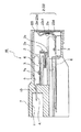
本発明のヒュージブルリンクユニット1Aは、図2に示すように、連結プレート部2と、該連結プレート部2の一側に連なった可溶体部3と、該可溶体部3に連結された端子部4とを有し、該端子部4が可溶体部3を介して連結プレート部2に連結され構成されたヒューズ回路体6と、外壁の一部に開口部7aを設けるとともにヒューズ回路体6が収容されるハウジング7と、を備えている。
As shown in FIG. 2, the fusible link unit 1 </ b> A of the present invention includes a
ハウジング7は、図1及び図2に示すように、絶縁性の合成樹脂により略直方体状に形成されており、ハウジング7の上面と該上面と連なり、かつ直交した一方の側面とに亘って、ハウジング7の短手方向に向けてヒューズ回路体6が挿入される開口部7aが形成されている。
As shown in FIGS. 1 and 2, the
ハウジング7内には、開口部7aに連続した回路体収容室9が形成されており、該回路体収容室9の側方には、回路体収容室9に連続して端子支持部10及びコネクタハウジング部11が形成されている。そして、端子支持部10及びコネクタハウジング部11が、図1に示すように、ハウジング7の開口部7aが形成された側面と相対する他方の側面に該ハウジング7の長手方向に並んで配置される。
A circuit
そして、図2に示すように、ハウジング7内に開口部7aよりハウジング7の短手方向に向けて二つのヒューズ回路体6が、端子部4を挿入先端として挿入されるようになっている。これにより、挿入された二つのヒューズ回路体6は、回路体収容室9内に並んで収容されて、ハウジング7の厚さ(端子部4に直交する)方向に積層配置される。
As shown in FIG. 2, two
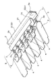
ヒューズ回路体6は、図示しない導電性の平板状のプレート材をプレス加工することにより一体に形成されており、連結プレート部2、可溶体部3及び端子部4が1枚のプレート材から一体に形成されている。
The
連結プレート部2は、図3に示すように、ヒューズ回路体6の複数の可溶体部3と端子部4に連結した共通端子部として構成されるとともにアース側のバスバープレートとして構成されている。連結プレート部2は、可溶体部3と端子部4とに連結されていない他側2aが連結プレート部の短手方向にU字状に延設されたU字状部2bを備えている。
As shown in FIG. 3, the connecting
可溶体部3は、連結プレート部2の一側に連結されるとともに細幅でクランク状に形成されており、クランク形状の中途部には、低融点金属3aが加締められて固定されている。そして、可溶体部3に、所定値以上の電流が流れると、その時の発熱で低融点金属3aを加締めた可溶体部3が溶断するようになっている。
The
端子部4は、可溶体部3に連結され、可溶体部3と端子部4を1組として、1つのヒューズエレメント部5を構成している。ヒューズエレメント部5は、前述のように端子部4が可溶体部3を介して連結プレート部2に連結されてヒューズ回路体6を構成するようになっており、本実施形態の場合、図3に示すように、複数のヒューズエレメント部5が連結プレート部2の一側に長手方向に連鎖状に連結されて1つのヒューズ回路体6を構成している。
The
蓋体8Aは、図2に示すように、ハウジング7に設けられた開口部7aに装着されるようになっている。蓋体8Aは、透明な材料で構成され、ハウジング7の開口部7aを塞ぐように断面く字状に形成されている。この蓋体8Aにより開口部7aが塞がれるとともに、ハウジング7の内部の状態をハウジング7の外部から目視できるようになっている。
As shown in FIG. 2, the lid 8 </ b> A is attached to an
また、蓋体8Aには、ハウジング7の厚さ(端子部4に直交する)方向に平行な側面に、ハウジング7内に突出する突部81が設けられている。突部81は、蓋体8Aと一体に形成されている。突部81には、図2に示すように、ハウジング7の厚さ(端子部4に直交する)方向に平行な蓋体8Aの側面に対して、一端が当該側面から離れる方向に、他端が当該側面に近づく方向に傾斜した傾斜面82が設けられている。
Further, the
傾斜面82は、突部81のハウジング7内側の側面に設けられている。傾斜面82は、表面が蒸着メッキ処理などが施されて鏡面化されている。そして、傾斜面82は、開口部7aを通してハウジング7内に侵入する光を可溶体部3に向かって反射させる。傾斜面82は、特許請求の範囲に記載の反射面を成している。
The
前述した構成のヒュージブルリンクユニット1Aは、ハウジング7の開口部7aよりハウジング7の短手方向に向けて、ヒューズ回路体6が端子部4を挿入先端として挿入されるようになっており、この挿入されたヒューズ回路体6が回路体収容室9内に収容されるとともに、ヒューズ回路体6の挿入先端である端子部4が回路体収容室9を通ってハウジング7の端子支持部10及びコネクタハウジング部11内に位置するように収容される。
In the fusible link unit 1A having the above-described configuration, the
ハウジング7の端子支持部10に配設されたヒューズ回路体6の端子部4には、図示しないケーブルが接続された端子金具を介してビス止め用の孔に通されている。
The
前述のケーブルには、図示しない各種電装品が接続されており、ケーブルのヒューズ回路体6への接続により、ヒュージブルリンクユニット1Aには、複数の電装品が接続されるようになっている。これにより、1つのヒュージブルリンクユニット1Aが、複数の電装品を集中管理することとなる。
Various electrical components (not shown) are connected to the cable described above, and a plurality of electrical components are connected to the fusible link unit 1A by connecting the cable to the
このようなヒュージブルリンクユニット1Aにおいては、バッテリ電源から電装品に供給される電気回路中に過電流が流れると、ヒュージブルリンクユニット1Aの可溶体部3が発熱によって溶断して、過電流から電気回路を保護する。
In such a fusible link unit 1A, when an overcurrent flows in an electric circuit supplied to an electrical component from a battery power source, the
また、ハウジング7の短手方向が水平方向を向くように車体に搭載されているので、ハウジング7の上部から蓋体8Aを介してハウジング7内に配されたヒューズ回路体6の可溶体部3の状態を目視できるようになっており、これにより、ヒュージブルリンクユニット1Aの保守点検を行うことができる。
Further, since the
前述した本実施形態のヒュージブルリンクユニット1Aは、図2に示すように、ハウジング7の短手方向が水平方向を向くように車体に載置されるいわゆる横置き型ヒュージブルリンクユニットとして構成されている。このため、前記ハウジング7内に収容された二つのヒューズ回路体6は、ハウジング7の短手方向に沿って水平方向を向くように積層配置されている。
As shown in FIG. 2, the fusible link unit 1A of the present embodiment described above is configured as a so-called horizontal type fusible link unit that is placed on the vehicle body so that the short side direction of the
さらに、ハウジング7内に積層配置された二つのヒューズ回路体6は、図2に示すように、回路体の間隔が小さく構成されており、二つのヒューズ回路体6が接近して配置されている。
Further, as shown in FIG. 2, the two
そして、蓋体8Aのハウジング7の厚さ(端子部4に直交する)方向に平行な側面に、ハウジング7内に突出し、かつ蓋体8Aと一体に形成された突部81に設けられた傾斜面82によって、開口部7aを通してハウジング7内に侵入する光を可溶体部3に向かって反射させることができ、このため、ハウジング7に収容され該ハウジング7内に積層配置された二つのヒューズ回路体6のうち図2中下側に配置された一方のヒューズ回路体6の可溶体部3を明るくすることによって、ヒューズ回路体6の可溶体部3が視認できるようになる。
And the inclination provided in the
また、ハウジング7に収容されたヒューズ回路体6を、ハウジング7の上部から蓋体8Aを介して視認すると、突部81に設けられた傾斜面82により可溶体部3の反射像が開口部7aへ反射されることとなり、前述した一方のヒューズ回路体6の可溶体部3が視認できるようになる。
Further, when the
さらに、突部81に設けられた傾斜面82が、可溶体部3の通電時の発熱による放射熱を外部へ反射することによって、ヒューズ回路体6の温度の上昇を抑制することができる。
Furthermore, the
また、傾斜面82の表面が、蒸着メッキ処理などが施されて鏡面化されているため、開口部7aに反射される可溶体部3の反射像が確実に視認できるようになる。
Further, since the surface of the
前述した本実施形態では、突部が蓋体8Aと一体に設けられていたが、突部は蓋体8Aと別部材として設けても良く、蓋体8Aの、開口部7aからハウジング7内に侵入する光を可溶体部3に向かって反射させるとともに可溶体部3の反射像を開口部7aへ反射させることができる位置に取り付け可能であれば良い。
In the above-described embodiment, the protrusion is provided integrally with the
次に、本発明の第2の実施形態にかかるヒュージブルリンクユニット1Bを、図4乃至6を参照して説明する。また、第1実施形態と同一の構成部分には同一の符号を付して説明を省略する。 Next, a fusible link unit 1B according to a second embodiment of the present invention will be described with reference to FIGS. Moreover, the same code | symbol is attached | subjected to the component same as 1st Embodiment, and description is abbreviate | omitted.
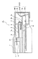
本発明のヒュージブルリンクユニット1Bは、図4に示すように、外壁の一部に開口部7aを設けるとともに該開口部7aを塞ぐ断面く字状に形成された蓋体8Bと、連結プレート部2と、該連結プレート部2の一側に連なった可溶体部3と、該可溶体部3に連結された端子部4と、を有し、該端子部4が可溶体部3を介して連結プレート部2に連結されてヒューズ回路体6を構成するとともに、二つのヒューズ回路体6がハウジング7の厚さ(端子部4と直交する)方向に積層配置されて収容されるハウジング7と、を備えている。
As shown in FIG. 4, the fusible link unit 1B of the present invention is provided with an
さらに、ハウジング7内に積層配置された二つのヒューズ回路体6のうち図5中下側に配置された一方の連結プレート部2(以下、符号22で示す。)は、可溶体部3と端子部4との両表面に平行でかつ可溶体部3と連なった平行部22dと、該平行部22dから立設しかつ可溶体部3と端子部4との両表面と交差した交差部22c1とを一体に形成されている。
Further, of the two
交差部22c1は、図5に示すように、可溶体部3に直交する方向に当該可溶体部3に連接されている。交差部22c1は、断面が可溶体部3から離れる方向に凹の曲面状に形成されている。さらに、交差部22c1の表面は、圧延加工や表面メッキ処理などが施されて鏡面化されている。そして、前述の交差部22c1は、開口部7aを通してハウジング7内に侵入する光を反射させ可溶体部3に集光する。交差部22c1は、特許請求の範囲に記載の反射面を成している。
As shown in FIG. 5, the intersecting portion 22 c 1 is connected to the
前述した本実施形態のヒュージブルリンクユニット1Bは、ハウジング7に積層配置された図4中下側に配置された一方のヒューズ回路体6を構成する連結プレート部22の交差部22c1は、可溶体部3から離れる方向に凹の曲面状に形成されているため、開口部7aを通してハウジング7内に侵入する光を可溶体部3に集光させることができ、このため、ハウジング7に収容された前述した一方のヒューズ回路体6の可溶体部3を明るくすることによって、ヒューズ回路体6の可溶体部3が視認できるようになる。
In the fusible link unit 1B of this embodiment described above, the intersecting portion 22c1 of the connecting
また、ハウジング7に収容されたヒューズ回路体6を、ハウジング7の上部から蓋体8Bを介して視認すると、連結プレート部22の交差部22c1により可溶体部3の反射像が前記開口部7aへ反射されることとなり、ヒューズ回路体6の可溶体部3が視認できるようになる。
Further, when the
さらに、連結プレート部22の交差部22c1が可溶体部3の通電時の発熱による放射熱を外部へ拡散して反射することによって、ヒューズ回路体6の温度の上昇を抑制することができる。
Further, the crossing portion 22c1 of the connecting
また、交差部22c1の表面が、圧延加工や表面メッキ処理などが施されて鏡面化されているため、開口部7aに反射される可溶体部3の反射像が確実に視認できるようになる。
Further, since the surface of the intersecting portion 22c1 is mirror-finished by rolling or surface plating, the reflected image of the
続いて、本発明の第3の実施形態にかかるヒュージブルリンクユニット1Cを、図7又は8を参照して説明する。また、第1及び第2実施形態と同一の構成部分には同一の符号を付して説明を省略する。 Subsequently, a fusible link unit 1 </ b> C according to a third embodiment of the present invention will be described with reference to FIG. 7 or 8. Further, the same components as those in the first and second embodiments are denoted by the same reference numerals, and the description thereof is omitted.
本発明のヒュージブルリンクユニット1Cは、図7に示すように、外壁の一部に開口部7aを設けるとともに該開口部7aを塞ぐ断面く字状に形成された蓋体8Bと、連結プレート部2と、該連結プレート部2の一側に連なった可溶体部3と、該可溶体部3に連結された端子部4と、を有し、該端子部4が可溶体部3を介して連結プレート部2に連結されてヒューズ回路体6を構成するとともに、二つのヒューズ回路体6がハウジング7の厚さ(端子部4と直交する)方向に積層配置されて収容されるハウジング7と、を備えている。
As shown in FIG. 7, the fusible link unit 1C of the present invention is provided with an
本実施形態の図7又は図8中下側に配置された一方のヒューズ回路体6の交差部22c2は、図7に示すように、連結プレート部22の可溶体部3に直交する方向に当該可溶体部3に連接されている。交差部22c2は、断面が可溶体部3に近づく方向に凸の曲面状に形成されている。さらに、交差部22c2は、表面が圧延加工や表面メッキ処理などが施されて鏡面化されている。そして、前述の交差部22c2は、開口部7aを通してハウジング7内に侵入する光を反射させ可溶体部3に向かって当該光を拡散させる。交差部22c2は、特許請求の範囲に記載の反射面を成している。
The crossing portion 22c2 of one
前述した第3の実施形態のヒュージブルリンクユニット1Cは、ハウジング7に収容されたヒューズ回路体6を構成する連結プレート部22の交差部22c2の断面が可溶体部3に近づく方向に凸の曲面状に形成されているため、開口部7aを通してハウジング7内に侵入する光を可溶体部3に向かって反射させてハウジング7内に当該光を拡散することができ、このため、ハウジング7に収容されたヒューズ回路体6の可溶体部3を明るくするとともに、ハウジング7内の広い範囲を明るくすることで、ヒューズ回路体6の可溶体部3が視認できるようになる。
The fusible link unit 1C of the third embodiment described above is a curved surface in which the cross section of the intersecting portion 22c2 of the connecting
また、ハウジング7に収容されたヒューズ回路体6を、ハウジング7の上部から蓋体8Bを介して視認すると、連結プレート部22の交差部22c2により、可溶体部3の反射像が交差部22c2の凸部中央で拡大して開口部7aへ反射されることとなり、ヒューズ回路体6の可溶体部3が視認できるようになる。
Further, when the
さらに、交差部22c2の表面が、圧延加工や表面メッキ処理などが施されて鏡面化されているため、開口部7aに反射される可溶体部3の反射像が確実に視認できるようになる。
Furthermore, since the surface of the intersection 22c2 is mirror-finished by rolling or surface plating, the reflected image of the
なお、前述した実施形態は本発明の代表的な形態を示したに過ぎず、本発明は、実施形態に限定されるものではない。本発明の骨子を逸脱しない範囲で種々変形して実施することができる。 In addition, embodiment mentioned above only showed the typical form of this invention, and this invention is not limited to embodiment. Various modifications can be made without departing from the scope of the present invention.
1A 1B 1C ヒュージブルリンクユニット
2 連結プレート部
3 可溶体部
4 端子部
6 ヒューズ回路体
7 ハウジング
7a 開口部
8A 8B 蓋体
22c1 22c2 交差部(反射面)
82 傾斜面(反射面)
1A 1B 1C
82 Inclined surface (reflective surface)
Claims (4)
外壁の一部に開口部を設けるとともに前記ヒューズ回路体を収容するハウジングと、を備えたヒュージブルリンクユニットにおいて、
前記ハウジング内に、前記開口部を通して前記ハウジング内に侵入する光を前記可溶体部に向かって反射する反射面が設けられ、前記反射面は、前記連結プレート部の一部であり、かつ前記連結プレート部に対して前記端子部から離れる方向に凹の曲面状に形成されていることを特徴とするヒュージブルリンクユニット。 A fuse circuit body having a plurality of terminal portions connected to the connecting plate portion via a fusible body portion;
In a fusible link unit comprising an opening in a part of the outer wall and housing the fuse circuit body,
A reflection surface is provided in the housing for reflecting light that enters the housing through the opening toward the fusible body portion, and the reflection surface is a part of the connection plate portion, and the connection A fusible link unit, wherein the fusible link unit is formed into a concave curved surface in a direction away from the terminal portion with respect to the plate portion .
外壁の一部に開口部を設けるとともに前記ヒューズ回路体を収容するハウジングと、を備えたヒュージブルリンクユニットにおいて、
前記ハウジング内に、前記開口部を通して前記ハウジング内に侵入する光を前記可溶体部に向かって反射する反射面が設けられ、前記反射面は、前記連結プレート部の一部であり、かつ前記連結プレート部に対して前記端子部に近づく方向に凸の曲面状に形成されていることを特徴とするヒュージブルリンクユニット。 A fuse circuit body having a plurality of terminal portions connected to the connecting plate portion via a fusible body portion;
In a fusible link unit comprising an opening in a part of the outer wall and housing the fuse circuit body,
A reflection surface is provided in the housing for reflecting light that enters the housing through the opening toward the fusible body portion, and the reflection surface is a part of the connection plate portion, and the connection features and to Ruhi-menu-di table link unit that it is formed in a convex curved shape in a direction approaching to the terminal portion to the plate portion.
Priority Applications (2)
| Application Number | Priority Date | Filing Date | Title |
|---|---|---|---|
| JP2006139997A JP4755018B2 (en) | 2006-05-19 | 2006-05-19 | Fusible link unit |
| US11/783,147 US7679484B2 (en) | 2006-05-19 | 2007-04-06 | Fusible link unit |
Applications Claiming Priority (1)
| Application Number | Priority Date | Filing Date | Title |
|---|---|---|---|
| JP2006139997A JP4755018B2 (en) | 2006-05-19 | 2006-05-19 | Fusible link unit |
Publications (2)
| Publication Number | Publication Date |
|---|---|
| JP2007311225A JP2007311225A (en) | 2007-11-29 |
| JP4755018B2 true JP4755018B2 (en) | 2011-08-24 |
Family
ID=38711454
Family Applications (1)
| Application Number | Title | Priority Date | Filing Date |
|---|---|---|---|
| JP2006139997A Expired - Fee Related JP4755018B2 (en) | 2006-05-19 | 2006-05-19 | Fusible link unit |
Country Status (2)
| Country | Link |
|---|---|
| US (1) | US7679484B2 (en) |
| JP (1) | JP4755018B2 (en) |
Families Citing this family (1)
| Publication number | Priority date | Publication date | Assignee | Title |
|---|---|---|---|---|
| US8610243B2 (en) | 2011-12-09 | 2013-12-17 | Globalfoundries Inc. | Metal e-fuse with intermetallic compound programming mechanism and methods of making same |
Citations (1)
| Publication number | Priority date | Publication date | Assignee | Title |
|---|---|---|---|---|
| JP2002358870A (en) * | 2001-05-31 | 2002-12-13 | Sumitomo Wiring Syst Ltd | Fuse box |
Family Cites Families (11)
| Publication number | Priority date | Publication date | Assignee | Title |
|---|---|---|---|---|
| US1902613A (en) * | 1929-07-22 | 1933-03-21 | Siemens Ag | Fuse |
| JPS5119245A (en) * | 1974-08-07 | 1976-02-16 | Toyota Motor Co Ltd | Kurei oyobi suireishikireikyakushisutemuosonaeta nainenkikan |
| US4035754A (en) * | 1975-06-06 | 1977-07-12 | General Motors Corporation | Fuse box, particularly for motor vehicles |
| JPS5733061A (en) * | 1980-08-05 | 1982-02-23 | Daifuku Machinery Works | Self-propelled truck |
| GB2178913A (en) * | 1985-07-23 | 1987-02-18 | Sydney Stanley Bosley | Electrical fuse |
| IT1282131B1 (en) * | 1996-04-24 | 1998-03-12 | Codognese Meccanotec | AUTOMOTIVE TYPE HIGH CURRENT FUSE. |
| US5889458A (en) * | 1997-10-29 | 1999-03-30 | Yazaki Corporation | Fuse assembly having radiation reflecting means |
| JP3814451B2 (en) * | 1999-12-03 | 2006-08-30 | 住友電装株式会社 | Manufacturing method of fuse |
| JP3966114B2 (en) * | 2002-07-01 | 2007-08-29 | 忠司 梅田 | Current fuse |
| DE102004052476B4 (en) * | 2003-10-31 | 2007-08-09 | Yazaki Corp. | fuse assembly |
| JP2005190735A (en) * | 2003-12-24 | 2005-07-14 | Yazaki Corp | Fusible link unit |
-
2006
- 2006-05-19 JP JP2006139997A patent/JP4755018B2/en not_active Expired - Fee Related
-
2007
- 2007-04-06 US US11/783,147 patent/US7679484B2/en not_active Expired - Fee Related
Patent Citations (1)
| Publication number | Priority date | Publication date | Assignee | Title |
|---|---|---|---|---|
| JP2002358870A (en) * | 2001-05-31 | 2002-12-13 | Sumitomo Wiring Syst Ltd | Fuse box |
Also Published As
| Publication number | Publication date |
|---|---|
| US7679484B2 (en) | 2010-03-16 |
| US20070268107A1 (en) | 2007-11-22 |
| JP2007311225A (en) | 2007-11-29 |
Similar Documents
| Publication | Publication Date | Title |
|---|---|---|
| JP4769621B2 (en) | Bus bar housed in in-vehicle electrical junction box | |
| JP4533827B2 (en) | Fusible link | |
| TW541560B (en) | Fuse | |
| JP4754333B2 (en) | Electronic component connection structure | |
| JP2008125317A (en) | Electrical connection box | |
| JP2007115580A (en) | Electric junction box | |
| US7713070B2 (en) | Electric connection box | |
| JP2005050577A (en) | Incomplete-fitting detection structure of bus bar in automobile-use electric connection box | |
| JP4755018B2 (en) | Fusible link unit | |
| WO2011065461A1 (en) | Circuit structure and electrical junction box | |
| JP2006115638A (en) | Electric junction box | |
| JP6309303B2 (en) | Electrical junction box | |
| JP2011097762A (en) | Plug-in fitting | |
| JP4412147B2 (en) | Electrical component equipment | |
| JP6374912B2 (en) | Fusible link unit | |
| JP2014236621A (en) | Electric connection box | |
| JP7346844B2 (en) | electronic module | |
| JP2007080709A (en) | Fusible link | |
| JP2016054196A (en) | Fitting structure for bus bar | |
| JP5532308B2 (en) | Circuit structure | |
| JP4309791B2 (en) | Fuse holder and fuse unit | |
| JP2006107965A (en) | Fuse block | |
| JP7123482B2 (en) | fusible link unit | |
| JP2019021582A (en) | Lighting device | |
| JP4001835B2 (en) | Fuse cavity structure and electrical junction box |
Legal Events
| Date | Code | Title | Description |
|---|---|---|---|
| A621 | Written request for application examination |
Free format text: JAPANESE INTERMEDIATE CODE: A621 Effective date: 20090417 |
|
| A977 | Report on retrieval |
Free format text: JAPANESE INTERMEDIATE CODE: A971007 Effective date: 20110210 |
|
| A131 | Notification of reasons for refusal |
Free format text: JAPANESE INTERMEDIATE CODE: A131 Effective date: 20110222 |
|
| A521 | Request for written amendment filed |
Free format text: JAPANESE INTERMEDIATE CODE: A523 Effective date: 20110421 |
|
| TRDD | Decision of grant or rejection written | ||
| A01 | Written decision to grant a patent or to grant a registration (utility model) |
Free format text: JAPANESE INTERMEDIATE CODE: A01 Effective date: 20110524 |
|
| A01 | Written decision to grant a patent or to grant a registration (utility model) |
Free format text: JAPANESE INTERMEDIATE CODE: A01 |
|
| A61 | First payment of annual fees (during grant procedure) |
Free format text: JAPANESE INTERMEDIATE CODE: A61 Effective date: 20110526 |
|
| FPAY | Renewal fee payment (event date is renewal date of database) |
Free format text: PAYMENT UNTIL: 20140603 Year of fee payment: 3 |
|
| R150 | Certificate of patent or registration of utility model |
Ref document number: 4755018 Country of ref document: JP Free format text: JAPANESE INTERMEDIATE CODE: R150 Free format text: JAPANESE INTERMEDIATE CODE: R150 |
|
| R250 | Receipt of annual fees |
Free format text: JAPANESE INTERMEDIATE CODE: R250 |
|
| R250 | Receipt of annual fees |
Free format text: JAPANESE INTERMEDIATE CODE: R250 |
|
| R250 | Receipt of annual fees |
Free format text: JAPANESE INTERMEDIATE CODE: R250 |
|
| R250 | Receipt of annual fees |
Free format text: JAPANESE INTERMEDIATE CODE: R250 |
|
| R250 | Receipt of annual fees |
Free format text: JAPANESE INTERMEDIATE CODE: R250 |
|
| R250 | Receipt of annual fees |
Free format text: JAPANESE INTERMEDIATE CODE: R250 |
|
| LAPS | Cancellation because of no payment of annual fees |