JP4753077B2 - GEAR DEVICE AND ELECTRIC POWER STEERING DEVICE EQUIPPED WITH THE SAME - Google Patents
GEAR DEVICE AND ELECTRIC POWER STEERING DEVICE EQUIPPED WITH THE SAME Download PDFInfo
- Publication number
- JP4753077B2 JP4753077B2 JP2006092088A JP2006092088A JP4753077B2 JP 4753077 B2 JP4753077 B2 JP 4753077B2 JP 2006092088 A JP2006092088 A JP 2006092088A JP 2006092088 A JP2006092088 A JP 2006092088A JP 4753077 B2 JP4753077 B2 JP 4753077B2
- Authority
- JP
- Japan
- Prior art keywords
- gear
- housing
- ridges
- driven gear
- lubricant
- Prior art date
- Legal status (The legal status is an assumption and is not a legal conclusion. Google has not performed a legal analysis and makes no representation as to the accuracy of the status listed.)
- Expired - Fee Related
Links
Images


Classifications
-
- F—MECHANICAL ENGINEERING; LIGHTING; HEATING; WEAPONS; BLASTING
- F16—ENGINEERING ELEMENTS AND UNITS; GENERAL MEASURES FOR PRODUCING AND MAINTAINING EFFECTIVE FUNCTIONING OF MACHINES OR INSTALLATIONS; THERMAL INSULATION IN GENERAL
- F16H—GEARING
- F16H57/00—General details of gearing
- F16H57/04—Features relating to lubrication or cooling or heating
- F16H57/042—Guidance of lubricant
- F16H57/0427—Guidance of lubricant on rotary parts, e.g. using baffles for collecting lubricant by centrifugal force
-
- B—PERFORMING OPERATIONS; TRANSPORTING
- B62—LAND VEHICLES FOR TRAVELLING OTHERWISE THAN ON RAILS
- B62D—MOTOR VEHICLES; TRAILERS
- B62D5/00—Power-assisted or power-driven steering
- B62D5/04—Power-assisted or power-driven steering electrical, e.g. using an electric servo-motor connected to, or forming part of, the steering gear
- B62D5/0409—Electric motor acting on the steering column
- B62D5/0412—Electric motor acting on the steering column the axes of motor and steering column being parallel
-
- F—MECHANICAL ENGINEERING; LIGHTING; HEATING; WEAPONS; BLASTING
- F16—ENGINEERING ELEMENTS AND UNITS; GENERAL MEASURES FOR PRODUCING AND MAINTAINING EFFECTIVE FUNCTIONING OF MACHINES OR INSTALLATIONS; THERMAL INSULATION IN GENERAL
- F16H—GEARING
- F16H57/00—General details of gearing
- F16H57/04—Features relating to lubrication or cooling or heating
- F16H57/042—Guidance of lubricant
- F16H57/0421—Guidance of lubricant on or within the casing, e.g. shields or baffles for collecting lubricant, tubes, pipes, grooves, channels or the like
-
- Y—GENERAL TAGGING OF NEW TECHNOLOGICAL DEVELOPMENTS; GENERAL TAGGING OF CROSS-SECTIONAL TECHNOLOGIES SPANNING OVER SEVERAL SECTIONS OF THE IPC; TECHNICAL SUBJECTS COVERED BY FORMER USPC CROSS-REFERENCE ART COLLECTIONS [XRACs] AND DIGESTS
- Y10—TECHNICAL SUBJECTS COVERED BY FORMER USPC
- Y10T—TECHNICAL SUBJECTS COVERED BY FORMER US CLASSIFICATION
- Y10T74/00—Machine element or mechanism
- Y10T74/19—Gearing
- Y10T74/19991—Lubrication
-
- Y—GENERAL TAGGING OF NEW TECHNOLOGICAL DEVELOPMENTS; GENERAL TAGGING OF CROSS-SECTIONAL TECHNOLOGIES SPANNING OVER SEVERAL SECTIONS OF THE IPC; TECHNICAL SUBJECTS COVERED BY FORMER USPC CROSS-REFERENCE ART COLLECTIONS [XRACs] AND DIGESTS
- Y10—TECHNICAL SUBJECTS COVERED BY FORMER USPC
- Y10T—TECHNICAL SUBJECTS COVERED BY FORMER US CLASSIFICATION
- Y10T74/00—Machine element or mechanism
- Y10T74/21—Elements
- Y10T74/2186—Gear casings
Abstract
Description
本発明は、歯車装置およびこれを備える電動パワーステアリング装置に関する。 The present invention relates to a gear device and an electric power steering device including the gear device.
電動モータ等の駆動源の出力を伝達するためのギヤ機構が知られている(例えば、特許文献1参照)。
特許文献1では、電動モータの出力回転を、遊星ギヤ機構を介して負荷に伝達すようにしている。具体的には、電動モータの出力軸にサンギヤが連結されており、サンギヤとリングギヤとの間に遊星ギヤが配置されている。遊星ギヤの側面には、潤滑油が溜められる凹溝が形成されており、遊星ギヤの回転(自転、公転)に伴う遠心力により、凹溝内の潤滑油が飛ばされる。これにより、潤滑油が各ギヤの歯部に跳ね掛けられる。 In Patent Document 1, output rotation of an electric motor is transmitted to a load via a planetary gear mechanism. Specifically, a sun gear is connected to the output shaft of the electric motor, and a planetary gear is disposed between the sun gear and the ring gear. A concave groove in which lubricating oil is stored is formed on the side surface of the planetary gear, and the lubricating oil in the concave groove is blown by a centrifugal force accompanying rotation (rotation, revolution) of the planetary gear. Thereby, lubricating oil splashes on the tooth part of each gear.
しかしながら、潤滑油を遠心力で周囲に十分に跳ね掛けるためには、凹溝が形成されたギヤの回転数を高くしなければならない。このため、十分な潤滑を行うことのできる運転条件が狭いものとなってしまう。例えば、電動モータの出力回転を舵取り機構に伝達する歯車機構では、舵取り機構に連なる従動歯車の回転数が比較的遅い(例えば、数rpm程度)ことにより、従動歯車の回転に伴う遠心力が小さい。したがって、潤滑油を十分に周囲に跳ね掛けることが困難で、十分な潤滑を行い難い。特に、グリースを潤滑に用いる場合、グリースを遠心力で飛ばすことはより困難となる。 However, in order to sufficiently splash the lubricating oil around the periphery by centrifugal force, the rotational speed of the gear in which the concave groove is formed must be increased. For this reason, the operating conditions under which sufficient lubrication can be performed become narrow. For example, in the gear mechanism that transmits the output rotation of the electric motor to the steering mechanism, the rotational speed of the driven gear connected to the steering mechanism is relatively slow (for example, about several rpm), so that the centrifugal force accompanying the rotation of the driven gear is small. . Therefore, it is difficult to sufficiently splash the lubricating oil around, and it is difficult to perform sufficient lubrication. In particular, when grease is used for lubrication, it becomes more difficult to fly the grease by centrifugal force.
同様の課題は、電動パワーステアリング装置に備えられる歯車装置に限らず、他の一般の歯車装置にも存在する。
本発明は、かかる背景のもとでなされたもので、より広範な運転条件下において十分な潤滑ができる歯車装置およびこれを備える電動パワーステアリング装置を提供することを目的とする。
The same problem exists not only in the gear device provided in the electric power steering device but also in other general gear devices.
The present invention has been made under such a background, and an object of the present invention is to provide a gear device capable of sufficient lubrication under a wider range of operating conditions and an electric power steering device including the gear device.
上記目的を達成するため、本発明は、互いに噛み合う複数の歯車(23,24)と、これら複数の歯車(23,24)を収容するハウジング(25)と、このハウジング(25)内に収容された潤滑剤(L)とを備え、上記複数の歯車(23,24)のなかから少なくとも1つ選択された歯車(24)の少なくとも一方の側面(32,52)、およびこれに対向するハウジング(25)の側面(57,60)に、上記選択された歯車(24)の周方向(C)に対して交差する方向(R,D2,D3)に延びる凸条(58,59,61,62)が設けられ、上記選択された歯車(24)の軸方向(S)に沿ってみたときに、上記選択された歯車(24)の回転に伴って、上記選択された歯車(24)の凸条(58,61)およびハウジング(25)の対応する凸条(59,62)が、上記選択された歯車(24)の軸方向(S)に部分的に対向して近接することにより、互いの間に表面張力を用いて潤滑剤(L)を保持可能な交差部(67a,67b,74a,74b)を形成するようにしてあることを特徴とする歯車装置(21)を提供するものである(請求項1)。 To achieve the above object, the present invention provides a plurality of gears (23, 24) that mesh with each other, a housing (25) that houses the plurality of gears (23, 24), and a housing (25). And at least one side surface (32, 52) of the gear (24) selected from at least one of the plurality of gears (23, 24), and a housing ( 25) on the side surfaces (57, 60) of the selected gear (24), the ridges (58, 59, 61, 62) extending in the direction (R, D2, D3) intersecting the circumferential direction (C). ) And the convexity of the selected gear (24) as the selected gear (24) rotates as viewed along the axial direction (S) of the selected gear (24). Article (58, 61) and housing (2 ) Corresponding ridges (59, 62) is, by close partially axially opposite (S) of the selected gear (24), a lubricant with a surface tension therebetween A gear device (21) is provided, characterized in that intersections (67a, 67b, 74a, 74b) capable of holding (L) are formed (claim 1).
なお、括弧内の英数字は、後述の実施形態における対応構成要素等を表す。以下、この項において同じ。
本発明によれば、選択された歯車の回転に伴って、交差部および交差部間に保持された潤滑剤を、凸条の延びる方向に移動させることができる。これにより、選択された歯車の歯部に向けて潤滑剤を移動させることができ、歯車同士の噛み合い部分に十分な量の潤滑剤を供給することができる。また、潤滑剤を交差部間に保持させて移動させることにより、潤滑剤の移動に遠心力を用いる必要がない。したがって、選択された歯車の回転数が数rpm程度の低い回転数であっても、潤滑剤を確実に移動して歯部に供給できる。広範な運転条件下で十分な潤滑ができる。また、潤滑剤として潤滑油を使用することができ、また潤滑剤としてグリースを使用することができ、より広範な運転条件下で十分な潤滑ができる。
In addition, the alphanumeric characters in parentheses represent corresponding components in the embodiments described later. The same applies hereinafter.
According to the present invention, the lubricant held between the intersecting portions and the intersecting portions can be moved in the extending direction of the ridge along with the rotation of the selected gear. Accordingly, the lubricant can be moved toward the tooth portion of the selected gear, and a sufficient amount of lubricant can be supplied to the meshing portion between the gears. Further, since the lubricant is moved while being held between the intersections, it is not necessary to use centrifugal force for the movement of the lubricant. Therefore, even if the rotation speed of the selected gear is as low as several rpm, the lubricant can be reliably moved and supplied to the tooth portion. Sufficient lubrication is possible under a wide range of operating conditions. In addition, lubricating oil can be used as the lubricant, and grease can be used as the lubricant, so that sufficient lubrication can be achieved under a wider range of operating conditions.
また、本発明において、上記選択された歯車(24)の凸条(58,61)およびハウジング(25)の対応する凸条(59,62)は、上記選択された歯車(24)の軸方向(S)に沿ってみたときに、歯車(24)の周方向(C)に対して相異なる交差角度(E1,E2,E3,E4)で交差している場合がある(請求項2)。この場合、選択された歯車の凸条の長手方向の向きと、ハウジングの対応する凸条の長手方向の向きとを歯車の周方向に対して相異ならせるという簡易な構成で、選択された歯車の軸方向に沿ってみたときに、これらの凸条を部分的に対向することができる。 In the present invention, the protrusion (58, 61) of the selected gear (24) and the corresponding protrusion (59, 62) of the housing (25) are arranged in the axial direction of the selected gear (24). When viewed along (S), there may be cases where they intersect at different angles (E1, E2, E3, E4) with respect to the circumferential direction (C) of the gear (24). In this case, the selected gear is configured with a simple configuration in which the longitudinal direction of the ridge of the selected gear is different from the longitudinal direction of the corresponding ridge of the housing with respect to the circumferential direction of the gear. These ridges can be partially opposed when viewed along the axial direction.
また、本発明において、上記選択された歯車(24)の軸方向(S)に沿ってみたときに、上記選択された歯車(24)の凸条(58,61)およびハウジング(25)の対応する凸条(59,62)は、歯車(24)の周方向(C)に対して互いに逆向きに傾斜している場合がある(請求項3)。この場合、選択された歯車の凸条の長手方向の向きと、ハウジングの対応する凸条の長手方向の向きとを歯車の周方向に対して逆向きに傾斜させるという簡易な構成で、選択された歯車の軸方向に沿ってみたときに、これらの凸条を部分的に対向することができる。 Further, in the present invention, when viewed along the axial direction (S) of the selected gear (24), the correspondence between the ridges (58, 61) of the selected gear (24) and the housing (25). The protruding ridges (59, 62) may be inclined in opposite directions with respect to the circumferential direction (C) of the gear (24). In this case, it is selected with a simple configuration in which the longitudinal direction of the selected ridge of the gear and the longitudinal direction of the corresponding ridge of the housing are inclined in the opposite direction with respect to the circumferential direction of the gear. When viewed along the axial direction of the gear, these ridges can be partially opposed.
また、本発明において、上記交差部(67a,67b、74a,74b)と上記選択された歯車(24)の中心(24a)との距離(G1,G2)が、上記選択された歯車(24)が所定の回転方向(C1)に回転するときに増大または減少する場合がある(請求項4)。この場合、選択された歯車が所定の回転方向に回転することにより、交差部間に保持された潤滑剤を、歯車の外径側または内径側に移動させることができる。 In the present invention, the distance (G1, G2) between the intersection (67a, 67b, 74a, 74b) and the center (24a) of the selected gear (24) is the selected gear (24). May increase or decrease when rotating in a predetermined rotational direction (C1). In this case, by rotating the selected gear in a predetermined rotation direction, the lubricant held between the intersecting portions can be moved to the outer diameter side or the inner diameter side of the gear.
また、本発明において、上記選択された歯車(24)の凸条(58,61)は当該歯車(24)の一対の側面(32,52)に設けられ、上記ハウジング(25)の凸条(59,62)は、上記選択された歯車(24)の各側面(32,52)の凸条(58,61)にそれぞれ対応する凸条(59,62)を含み、上記選択された歯車(24)の回転に伴って、上記選択された歯車(24)の一方の側面(32)の凸条(58)に関する交差部(67a,67b)と上記選択された歯車(24)の中心(24a)との距離(G1)が増大するときに、他方の側面(52)の凸条(61)に関する交差部(74a,74b)と上記選択された歯車(24)の中心(24a)との距離(G2)が減少するようにしてある場合がある(請求項5)。この場合、選択された歯車が何れの回転方向に回転したときでも、選択された歯車の中心から離れる潤滑剤と、選択された歯車の中心に近づく潤滑剤の双方が存在することとなる。これにより、選択された歯車の回転方向の何れにおいても、潤滑剤を歯車の内径側および外径側に供給でき、その結果、潤滑剤を確実に歯車の歯部に向けて移動することができる。 In the present invention, the protrusions (58, 61) of the selected gear (24) are provided on the pair of side surfaces (32, 52) of the gear (24), and the protrusions ( 59, 62) includes ridges (59, 62) respectively corresponding to the ridges (58, 61) of the side surfaces (32, 52) of the selected gear (24), and the selected gear ( With the rotation of 24), the intersecting portion (67a, 67b) related to the ridge (58) on one side surface (32) of the selected gear (24) and the center (24a) of the selected gear (24). The distance between the intersection (74a, 74b) related to the ridge (61) on the other side surface (52) and the center (24a) of the selected gear (24) when the distance (G1) to the other side (52) increases. (G2) may decrease (claim 5). In this case, even when the selected gear rotates in any rotation direction, both the lubricant leaving the center of the selected gear and the lubricant approaching the center of the selected gear are present. Thereby, in any of the rotation directions of the selected gear, the lubricant can be supplied to the inner diameter side and the outer diameter side of the gear, and as a result, the lubricant can be reliably moved toward the tooth portion of the gear. .
また、本発明において、上記選択された歯車(24)の軸方向(S)が鉛直方向(V)に対して交差している場合がある(請求項6)。この場合、振動や自重等によって下方に落下した潤滑剤を、上方に上げて循環させることができる。
また、本発明において、上記の歯車装置(21)を用いて、操舵補助用の電動モータ(20)の出力回転を舵取り機構(22)に伝達する場合がある(請求項7)。この場合、潤滑剤として、潤滑油よりも粘性の高いグリースを用いて油漏れを良好に防止でき、且つ数rpm程度の低い回転数でも十分な潤滑を行うことのできる電動パワーステアリング装置を実現できる。
In the present invention, the axial direction (S) of the selected gear (24) may intersect the vertical direction (V). In this case, the lubricant that has fallen downward due to vibration, dead weight, etc. can be raised upward and circulated.
In the present invention, the output rotation of the steering assist electric motor (20) may be transmitted to the steering mechanism (22) using the gear device (21). In this case, it is possible to realize an electric power steering device that can prevent oil leakage satisfactorily by using grease having a viscosity higher than that of the lubricating oil as a lubricant, and can perform sufficient lubrication even at a low rotational speed of about several rpm. .
本発明の好ましい実施の形態を添付図面を参照しつつ説明する。
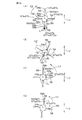
図1は、本発明の一実施の形態の電動パワーステアリング装置1の概略構成を示す模式図である。図1を参照して、電動パワーステアリング装置1は、ステアリングホイール等の操舵部材2に連結されているステアリングシャフト3と、ステアリングシャフト3に自在継手4を介して連結されている中間軸5と、この中間軸5に自在継手6を介して連結されているピニオン軸7と、ピニオン軸7の先端部に設けられたピニオン8に噛み合うラック9を形成して車両の左右方向に延びるラック軸10とを有している。
Preferred embodiments of the present invention will be described with reference to the accompanying drawings.
FIG. 1 is a schematic diagram showing a schematic configuration of an electric power steering apparatus 1 according to an embodiment of the present invention. Referring to FIG. 1, an electric power steering device 1 includes a steering shaft 3 connected to a steering member 2 such as a steering wheel, an
ラック軸10の両端部にはそれぞれタイロッド11が連結されており、各タイロッド11は、対応するナックルアーム(図示せず)を介して対応する車輪12に連結されている。操舵部材2が操作されてステアリングシャフト3が回転されると、この回転は中間軸5等を介してピニオン8に伝達され、ピニオン8およびラック9によって、車両の左右方向に沿うラック軸10の直線運動に変換される。これにより車輪12の転舵が達成される。
ステアリングシャフト3は、操舵部材2に連なる入力軸としての第1の操舵軸13と、自在継手4に連なる出力軸としての第2の操舵軸14とを有している。これら第1および第2の操舵軸13,14は、トーションバー15を介して同軸上に互いに連結されている。
トーションバー15の近傍には、トーションバー15のねじれに起因する第1の操舵軸13と第2の操舵軸14との相対回転変位量を検出するトルクセンサ16が設けられている。このトルクセンサ16の検出信号は、制御部17に与えられる。制御部17は、トルクセンサ16からの検出信号に基づいて操舵部材2に加えられた操舵トルクを算出する。そして、算出した操舵トルクや車速センサ18からの車速検出信号等に基づいて、ドライバ19を介して操舵補助用の電動モータ20の駆動を制御する。これにより、電動モータ20が駆動し、その出力回転(動力)が、歯車装置としての減速機21で減速されて第2の操舵軸14へ伝達される。第2の操舵軸14に伝えられた動力は、さらに中間軸5等を介して、上記ラック軸10、タイロッド11およびナックルアーム等を含む舵取り機構22に伝えられ、運転者の操舵が補助される。
The steering shaft 3 has a
In the vicinity of the
減速機21は、複数の歯車としての駆動ギヤ23および従動ギヤ24と、これら駆動ギヤ23および従動ギヤ24を収容するハウジング25とを含んでいる。
駆動ギヤ23は、電動モータ20の出力軸20aに連なる小歯車であり、従動ギヤ24は、駆動ギヤ23に噛み合い第2の操舵軸14に連なる大歯車である。
図2は、図1の減速機21周辺の要部の断面図である。図2を参照して、ハウジング25は、アルミニウム合金を用いて形成された、全体として筒状をなすものであり、第1のハウジング25aと第2のハウジング25bとを備えている。これら第1および第2のハウジング25a,25bは、ステアリングシャフト3の軸方向S(従動ギヤ24の軸方向でもある)に互いに対向している。
The
The
FIG. 2 is a cross-sectional view of a main part around the
第1のハウジング25aの一端(上端)の外周部41と第2のハウジング25bの一端(下端)の外周部42とは、互いに当接されており、ボルト(図示せず)を用いて互いに固定されている。第1および第2のハウジング25a,25bは、車体(図示せず)にボルト等を用いて支持されている。第1のハウジング25aには、鉛直方向Vに関する上端に環状のフランジ部43が設けられており、電動モータ20のハウジング44が嵌合固定されている。
The outer
駆動ギヤ23および従動ギヤ24は、それぞれ、例えばはすば歯車からなり、これら駆動ギヤ23および従動ギヤ24によって平行軸歯車機構が形成されている。なお、駆動ギヤ23および従動ギヤ24は、それぞれ、平歯車等であってもよい。また、駆動ギヤとしてウォーム軸を用い、被動ギヤとしてウォームホイールを用い、ウォーム減速機構を構成してもよい。
The
駆動ギヤ23の軸線23aおよび従動ギヤ24の中心としての軸線24aは、それぞれ、ステアリングシャフト3の軸方向Sに平行であり、鉛直方向Vに対して交差している。駆動ギヤ23と従動ギヤ24との噛み合い領域Aには、適度なバックラッシが設けられている。この噛み合い領域Aは、鉛直方向Vに関する従動ギヤ24の上端に位置している。
ハウジング25内には、潤滑剤Lが収容されており、これら駆動ギヤ23と従動ギヤ25との噛み合い領域Aに潤滑剤Lが存在している。潤滑剤Lは、例えばグリースである。
The axis 23a of the
Lubricant L is accommodated in the
駆動ギヤ23は、従動ギヤ24に噛み合う歯部26と、歯部26の一対の端部からそれぞれ延設される一対の支軸27,28とを含んでいる。一方の支軸27は、電動モータ20の出力軸20aにスプライン嵌合等により一体回転可能に連結されている。一方の支軸27および他方の支軸28のそれぞれには、駆動ギヤ23を回転自在に支持する第1および第2の軸受29,30が設けられている。
The
第1および第2の軸受29,30は、アンギュラ玉軸受等の転がり軸受からなる。これら第1および第2の軸受29,30の内輪29a,30aが、対応する支軸27,28のそれぞれに一体回転可能に外嵌されている。
第1の軸受29の外輪29bが、第1のハウジング25aの軸受保持孔46に相対回転を規制されて嵌合されている。第2の軸受30の外輪30bが、第2のハウジング25bの軸受保持孔47に相対回転を規制されて嵌合されている。
The first and
The
従動ギヤ24は、ステアリングシャフト3の第2の操舵軸14に一体回転可能且つ軸方向に相対移動不能に外嵌されており、外径部64に歯部31が形成されている。この歯部31は、駆動ギヤ23の歯部26と噛み合っている。従動ギヤ24の一側面32が、第2の操舵軸14の環状の段部33に受けられて軸方向Sの一方の相対移動が規制されている。
The driven
従動ギヤ24の支軸としての上記第2の操舵軸14には、従動ギヤ24を回転自在に支持するための第3および第4の軸受34,35が設けられている。各第3および第4の軸受34,35は、アンギュラ玉軸受等の転がり軸受からなり、従動ギヤ24を軸方向に挟んでいる。各第3および第4の軸受34,35の内輪34a,35aは、第2の操舵軸14に一体回転可能に外嵌されている。
The
第3の軸受34の外輪34bが、第1のハウジング25aの軸受保持孔48に相対回転を規制されて嵌合されている。第4の軸受35の外輪35bが、第2のハウジング25bの軸受保持孔49に相対回転を規制されて嵌合されている。
第1および第2の軸受29,30は、以下のようにして軸方向に位置決めされるとともに、予圧を付与されている。すなわち、第2の軸受30の外輪30bは、第2のハウジング25bの段部36に当接し位置決めされている。第2の軸受30の内輪30aは、駆動ギヤ23の他端部の位置決め段部37に当接することにより、駆動ギヤ23の一端部側(電動モータ側)への移動が規制されている。
The
The first and
第1の軸受29の内輪29aは、一方の支軸27の位置決め段部38に当接することにより、駆動ギヤ23の他端部側への移動が規制されている。第1の軸受29の外輪29bは、予圧調整用のねじ部材39により、第2の軸受30側へ付勢されている。
ねじ部材39は、第1のハウジング25aに形成されるねじ孔40にねじ込まれることにより、第1および第2の軸受29,30に予圧を付与すると共に、駆動ギヤ23を軸方向に位置決めしている。ロックナット50が、予圧調整後のねじ部材39を止定するためにねじ部材39に係合されている。
The
The
第3および第4の軸受34,35は、以下のようにして軸方向に位置決めされるとともに、予圧を付与されている。すなわち、第4の軸受35の外輪35bは、第2のハウジング25bの段部51に当接し位置決めされている。第4の軸受35の内輪35aは、従動ギヤ24の他側面52に当接することにより、従動ギヤ24の一端部側(第3の軸受34側)への移動が規制されている。この第4の軸受35の内輪35aは、第2の操舵軸14にねじ込まれたねじ部材53と上記一側面52とによって軸方向Sに挟まれている。
The third and
第3の軸受34の内輪33aは、前述したように、従動ギヤ24の一側面32に当接することにより、第4の軸受35側への移動が規制されている。第3の軸受34の外輪34bは、予圧調整用のねじ部材54により、第4の軸受35側へ付勢されている。
ねじ部材54は、第1のハウジング25aに形成されるねじ孔55にねじ込まれることにより、第3および第4の軸受34,35に予圧を付与すると共に、従動ギヤ24を軸方向Sに位置決めしている。ロックナット56が、予圧調整後のねじ部材54を止定するためにねじ部材54に係合されている。
As described above, the inner ring 33a of the
The
図3は、図2の一部拡大図である。図3を参照して、本実施の形態の特徴とするところは、選択された歯車としての上記従動ギヤ24と第1のハウジング25aとの間にある潤滑剤L(L1)、および上記従動ギヤ24と第2のハウジング25bとの間にある潤滑剤L(L2)の双方を、従動ギヤ24の回転動作に伴い、従動ギヤ24の周方向と交差する方向に移動できるようにしている点にある。
FIG. 3 is a partially enlarged view of FIG. Referring to FIG. 3, the present embodiment is characterized in that lubricant L (L1) between the driven
具体的には、従動ギヤ24の一側面32と、この一側面32に相対向する第1のハウジング25aの一側面57のそれぞれに、1ないし複数の凸条58,59(リブ)が設けられている。
同様に、従動ギヤ24の他側面52と、この他側面52に相対向する第2のハウジング25bの一側面60のそれぞれに、1ないし複数の凸条61,62(リブ)が設けられている。
Specifically, one or a plurality of
Similarly, one or a plurality of
図4は、図2のIV−IV線に沿う従動ギヤ24の断面図である。図5は、図2のV−V線に沿う要部の断面図であり、第1のハウジング25aおよび凸条58の一部のみを図示している。図6は、図2のVI−VI線に沿う要部の断面図である。図7は、図2のVII−VII線に沿う従動ギヤ24の断面図である。図8は、図2のVIII−VIII線に沿う要部の断面図であり、第2のハウジング25bと凸条61の一部のみを図示している。図9は、図2のIX−IX線に沿う要部の断面図である。
4 is a cross-sectional view of the driven
図3および図4を参照して、従動ギヤ24の一側面32は、軸方向Sに直交して延びる平面である。一側面32には、従動ギヤ24の内径部63と外径部64との間に複数の凹部65が形成されている。これらの凹部65は、軸方向Sに沿ってみて、それぞれ扇形形状をなしている。従動ギヤ24の周方向Cに隣り合う凹部65間に、凸条58が設けられている。各凸条58は、周方向Cに等間隔に配置されている。
With reference to FIGS. 3 and 4, one
なお、一側面32における凸条58は、1つ,2つまたは3つでもよいし、5つ以上あってもよい。
各凸条58は、内径部63と外径部64との間に跨って形成されており、周方向Cに対して交差する方向としての第1の方向である径方向Rに沿って延びている。すなわち、各凸条58は、周方向Cに対して略90°をなして交差しており、放射状に延びている。なお、各凸条58は、周方向Cに対して90°未満の角度なして交差していてもよい。各凸条58は、周方向Cに所定の幅Bを有している。
In addition, the number of the
Each
内径部63は、環状に形成されて各凸条58の一端部58a同士を互いに接続している。また、外径部64は、環状に形成されて各凸条58の他端部58b同士を互いに接続している。
図3および図5を参照して、第1のハウジング25aの一側面57は、軸方向Sと直交して延びている。第1のハウジング25aの凸条59は、この一側面57に突設されている。
The
Referring to FIGS. 3 and 5, one
なお、本実施の形態では、前記凸条58の数に対応して凸条59が周方向Cに等間隔に4つ設けられているが、一側面57における凸条59は、1つ,2つまたは3つでもよいし、5つ以上あってもよい。
一側面57には、軸受保持孔48(第3の軸受34を支持する軸受保持孔48)を取り囲む環状の内径部66が突設されており、上記各凸条59は、当該内径部66から、周方向Cに対して交差する方向としての第2の方向D2に沿って延びている。第2の方向D2は、例えば、周方向Cに対して数十°(例えば50°)程度の角度をなしている。図5に示す断面において(従動ギヤ24から第1のハウジング25aをみて)、各凸条59の一端部59aは、他端部59bに対して周方向他方C2にねじれている。
In the present embodiment, four
An annular
軸方向Sに沿ってみたとき、凸条58は、周方向Cに対して交差角度E1で交差しており、凸条59は、周方向Cに対して交差角度E2で交差している。軸方向Sに沿ってみたとき、上記対をなす凸条58,59は、周方向Cに対して互いに逆向きに傾斜しており、当該周方向Cに対して相異なる交差角度E1,E2で交差している。
各凸条59の一端部59aは、内径部66によって互いに接続されている。各凸条59の他端部59bは、従動ギヤ24の歯部31と軸方向Sに対向している。1つの凸条59(591)の他端部59bは、各ギヤ23,24の噛み合い領域Aに近接している。図2を参照して、別の1つの凸条59(592)の他端部59bは、鉛直方向Vに関する第1のハウジング25aの一側面57の下端に位置している。
When viewed along the axial direction S, the
One
再び図3および図5を参照して、軸方向Sに沿ってみたとき、従動ギヤ24の回転に伴って、従動ギヤ24の凸条58(図5において、一部を2点鎖線で図示)および第1のハウジング25aの凸条59が、軸方向Sに部分的に対向することにより、互いの間に潤滑剤Lを保持可能な交差部67a,67bを形成する。
各凸条59の頂面68および内径部66の頂面69は、面一に形成されて従動ギヤ24の一側面32と平行であり、互いに近接している。相対向する凸条58,59間の間隔F1は、潤滑剤Lが交差部67a,67b間で表面張力によって保持される程度に近接されている。
3 and 5 again, when viewed along the axial direction S, as the driven
The
従動ギヤ24が所定の回転方向としての周方向一方C1に回転すると、交差部67a,67bと従動ギヤ24の軸線24aとの距離G1が増大し、従動ギヤ24が周方向他方C2に回転すると、交差部67a,67bと従動ギヤ24の軸線24aとの距離G1が減少する。これにより、交差部67a,67b間に保持された潤滑剤Lが移動し、軸線24aとの距離(距離G1)が変動する。
When the driven
図6を参照して、上記対をなす凸条58,59は、周方向一方C1に関して相対向する側部70,71を含んでいる。これらの側部70,71は、滑らかな曲面に形成されている。これにより、従動ギヤ24が周方向一方C1に回転したときに、これらの側部70,71に保持されている潤滑剤Lを交差部67a,67b間に導入し易くできる。したがって、従動ギヤ24の歯部に移動される潤滑剤Lの量をより多くすることができる。
Referring to FIG. 6, the pair of protruding
図2および図7を参照して、従動ギヤ24の一側面32と他側面52とは、軸方向Sに直交する仮想の平面を中心として対称な形状に形成されており、一側面32と他側面52とはそれぞれ同様の構成を有している。
具体的には、従動ギヤ24の他側面52は、軸方向Sに直交して延びる平面である。他側面52には、従動ギヤ24の内径部63と外径部64との間に複数の凹部72が形成されている。これらの凹部72は、軸方向Sにみてそれぞれ扇形形状をなしている。従動ギヤ24の周方向Cに隣り合う凹部72間に、凸条61が設けられている。各凸条61は、周方向Cに等間隔に配置されている。
Referring to FIGS. 2 and 7, one
Specifically, the other side surface 52 of the driven
なお、一側面52における凸条61は、1つ,2つまたは3つでもよいし、5つ以上あってもよい。
各凸条61は、内径部63と外径部64との間に跨って形成されており、周方向Cに対して交差する方向としての第1の方向である径方向Rに沿って延びている。すなわち、各凸条61は、周方向Cに対して略90°をなして交差しており、放射状に延びている。なお、各凸条61は、周方向Cに対して90°未満の角度なして交差していてもよい。各凸条61は、周方向Cに所定の幅Bを有している。
The
Each
内径部63は、各凸条61の一端部61a同士を互いに接続している。また、外径部64は、各凸条61の他端部61b同士を互いに接続している。
図3および図8を参照して、第2のハウジング25bの一側面60は、軸方向Sと直交して延びている。第2のハウジング25bの凸条62は、この一側面60に突設されている。
The
Referring to FIGS. 3 and 8, one
なお、本実施の形態では、従動ギヤ24の他側面52の凸条61の数に対応して凸条62が周方向Cに等間隔に4つ設けられているが、一側面60における凸条62は、1つ,2つまたは3つでもよいし、5つ以上あってもよい。
一側面60には、前記軸受保持孔49(第4の軸受35を保持する軸受保持孔49)を取り囲む環状の内径部73が突設されており、上記各凸条62は、当該内径部73から、周方向Cに対して交差する方向としての第3の方向D3に沿って延びている。第3の方向D3は、例えば、周方向Cに対して数十°(例えば50°)程度の角度をなしている。図8に示す断面において(軸方向Sのうち従動ギヤ24を向く方向にみて)、各凸条62の一端部62aは、他端部62bに対して周方向一方C1にねじれている。
In the present embodiment, four
An annular
すなわち、軸方向Sに沿ってみたときにおいて、第1のハウジング25aの凸条59(図5参照)と第2のハウジング25bの凸条62(図8参照)とは、周方向Cに対して互いに逆向きに傾斜している。
図3および図8を参照して、軸方向Sに沿ってみたとき、凸条61は、周方向Cに対して交差角度E3で交差しており、凸条62(図8において、凸条62の一部を図示)は、周方向Cに対して交差角度E4で交差している。軸方向Sに沿ってみたとき、対をなす凸条61,62は、周方向Cに対して互いに逆向きに傾斜しており、当該周方向Cに対して相異なる交差角度E3,E4で交差している。
That is, when viewed along the axial direction S, the ridge 59 (see FIG. 5) of the
3 and 8, when viewed along the axial direction S, the
各凸条62の一端部62aは、内径部73によって互いに接続されている。各凸条62の他端部62bは、従動ギヤ24の歯部31と軸方向Sに対向している。1つの凸条62(621)の他端部62bは、各ギヤ23,24の噛み合い領域Aに近接している。図2を参照して、別の凸条62(622)の他端部62bは、鉛直方向Vに関する第2のハウジング25bの一側面60の下端に位置している。
One
図3および図8を参照して、軸方向Sに沿ってみたとき、従動ギヤ24の回転に伴って、従動ギヤ24の凸条61および第2のハウジング25bの凸条62が、軸方向Sに部分的に対向することにより、互いの間に潤滑剤Lを保持可能な交差部74a,74bを形成する。
各凸条62の頂面75および内径部73の頂面76は、面一に形成されて従動ギヤ24の他側面52と平行であり、互いに近接している。相対向する凸条61,62間の間隔F2は、潤滑剤Lが交差部74a,74b間で表面張力によって保持される程度に近接されている。
With reference to FIGS. 3 and 8, when viewed along the axial direction S, as the driven
The
従動ギヤ24が周方向他方C2に回転すると、交差部74a,74bと従動ギヤ24の軸線24aとの距離G2が増大し、従動ギヤ24が周方向一方C1に回転すると、交差部74a,74bと従動ギヤ24の軸線24aとの距離G2が減少する。これにより、交差部74a,74b間に保持された潤滑剤Lが移動し、軸線24aとの距離(距離G2)が変動する。
When the driven
図3および図5を参照して、上記の構成により、従動ギヤ24の回転に伴って、従動ギヤ24の一側面32に関する交差部67a,67bと従動ギヤ24の軸線24aとの距離G1が増大するときに、図3および図8に示すように、従動ギヤ24の他側面52に関する交差部74a,74bと従動ギヤ24の軸線24aとの距離G2が減少する。
同様に、従動ギヤ24の回転に伴って、従動ギヤ24の他側面52に関する交差部74a,74bと従動ギヤ24の軸線24aとの距離G2が増大するときに、図3および図5に示すように、従動ギヤ24の一側面32に関する交差部67a,67bと従動ギヤ24の軸線24aとの距離G1が減少する。
With reference to FIGS. 3 and 5, the above configuration increases the distance G <b> 1 between the intersecting
Similarly, when the distance G2 between the intersecting
図9を参照して、対をなす凸条61,62は、周方向他方C2に相対向する側部77,78を含んでいる。これらの側部77,78は、滑らかな曲面に形成されている。これにより、従動ギヤ24が周方向他方C2に回転したときに、これらの側部77,78に保持されている潤滑剤Lを交差部74a,74b間に導入し易くできる。したがって、従動ギヤ24の歯部に移動される潤滑剤Lの量をより多くすることができる。
Referring to FIG. 9, the pair of protruding
図10(A)〜(D)は、それぞれ、凸条58,59による潤滑剤Lの移動について説明するための要部の模式的な図である。図11(A)〜(D)は、それぞれ、凸条61,62による潤滑剤Lの移動について説明するための要部の模式的な図である。
以上の概略構成を有する電動パワーステアリング装置では、以下の動作が行われる。すなわち、図2を参照して、潤滑剤Lの一部は、自重や各ギヤ23,24からの振動や、各歯車23,24同士の噛み合い等によって、噛み合い領域Aから出て、従動ギヤ24の一側面32と第1のハウジング25aの一側面57との間を落下する。
FIGS. 10A to 10D are schematic views of the main part for explaining the movement of the lubricant L by the
In the electric power steering apparatus having the above schematic configuration, the following operation is performed. That is, referring to FIG. 2, a part of the lubricant L comes out of the meshing area A due to its own weight, vibrations from the
図2および図10(A)に示すように、上記潤滑剤Lの一部が落下して鉛直方向Vの下端にある状態から従動ギヤ24が周方向他方C2に回転すると、鉛直方向Vの下端にある潤滑剤Lは、鉛直方向Vの下端にある凸条592の他端部59bとこれに対向する凸条58の他端部58bの交差部67a,67b(671a,672b)間に保持される。
従動ギヤ24が周方向他方C2にさらに回転すると、図10(B)に示すように、交差部671a,672bと軸線24aとの距離G1が短くなり、潤滑剤Lが第1のハウジング25aの内径部66側に移動される。
As shown in FIGS. 2 and 10A, when the driven
When the driven
図10(C)を参照して、内径部66側に潤滑剤Lがある状態から、従動ギヤ24が周方向一方C1に回転すると、内径部66付近に保持された潤滑剤Lは、鉛直方向Vの上方にある凸条591の一端部59aと、これに対応する従動ギヤ24の凸条58の一端部58aとの間に形成される交差部67a,67b間に保持される。図10(D)に示すように、このときの交差部67a,67bの移動に伴い、潤滑剤Lは凸条591の他端部59bにまで移動され、当該他端部59bから噛み合い領域A(図2参照)に供給される。
Referring to FIG. 10C, when the driven
また、図2に示すように、潤滑剤Lの一部は、自重や各ギヤ23,24からの振動や、各歯車23,24同士の噛み合い等によって、噛み合い領域Aから出て、従動ギヤ24の他側面52と第2のハウジング25bの一側面60との間を落下する。
図2および図11(A)に示すように、潤滑剤Lが落下して鉛直方向Vの下端にある状態から従動ギヤ24が周方向一方C1に回転すると、鉛直方向Vの下端にある潤滑剤Lは、鉛直方向Vの下端にある凸条621の他端部62bとこれに対向する凸条61の他端部61bの交差部74a,74b(741a,741b)間に保持される。
Further, as shown in FIG. 2, a part of the lubricant L comes out of the meshing area A due to its own weight, vibration from the
As shown in FIG. 2 and FIG. 11A, when the lubricant L falls and the driven
従動ギヤ24が周方向一方C1にさらに回転すると、図11(B)に示すように、交差部74a,74bと軸線24aとの距離G2が短くなり、潤滑剤Lが第2のハウジング25bの内径部73側に移動される。
図11(C)を参照して、内径部73側に潤滑剤Lがある状態から、従動ギヤ24が周方向他方C2に回転すると、内径部73に保持された潤滑剤Lは、鉛直方向Vの上方にある凸条621の一端部62aと、これに対応する従動ギヤ24の凸条61の一端部61aとの間に形成される交差部741a,741b間に保持される。図11(D)に示すように、この交差部741a,741bの移動に伴い、潤滑剤Lは凸条621の他端部62bにまで移動され、当該他端部62bから噛み合い領域A(図2参照)に供給される。
When the driven
Referring to FIG. 11C, when the driven
以上説明したように、本実施の形態によれば、以下の作用効果を奏することができる。すなわち、従動ギヤ24の回転に伴って、相交差する交差部67a,67b、交差部74a,74b間のそれぞれに保持された潤滑剤Lを、対応する凸条59,62の延びる方向に移動させることができる。これにより、従動ギヤ24の歯部31に向けて潤滑剤Lを移動させることができ、ギヤ23,24同士の噛み合い領域Aに十分な量の潤滑剤Lを供給することができる。
As described above, according to the present embodiment, the following operational effects can be achieved. That is, as the driven
従来の構成、すなわち、相対向する凸条が設けられていない構成では、噛み合い領域でのギヤ同士の噛み合い等により押し出された潤滑剤を、噛み合い領域に戻すための構成が無く、噛み合い領域での潤滑剤の不足(潤滑不良)による歯面の摩耗等が問題となっていた。しかしながら、本実施の形態によれば、潤滑剤を外部から追加することなく、このような潤滑不良を防止できる。 In the conventional configuration, i.e., the configuration in which the protruding ridges facing each other are not provided, there is no configuration for returning the lubricant pushed out by the meshing of the gears in the meshing region to the meshing region, and in the meshing region. Tooth surface wear due to lack of lubricant (poor lubrication) has been a problem. However, according to the present embodiment, such poor lubrication can be prevented without adding a lubricant from the outside.
また、潤滑剤Lを対応する交差部67a,67b,74a,74b間に保持させて移動させることにより、潤滑剤Lの移動に遠心力を用いる必要がない。したがって、従動ギヤ24の回転数が数rpm程度の低い回転数であっても、潤滑剤Lを確実に上方に移動して歯部31(噛み合い領域A)に供給できる。広範な運転条件下で十分な潤滑ができる。また、潤滑剤Lとして潤滑油を使用することができ、また潤滑剤Lとしてグリースを使用することができ、より広範な運転条件下で十分な潤滑ができる。
Further, since the lubricant L is held and moved between the
さらに、従動ギヤ24の一側面32側にある相対向する凸条58,59は、軸方向Sに沿ってみたときに、周方向Cに対して相異なる交差角度E1,E2で交差している。このように、従動ギヤ24の凸条58の長手方向の向きと、第1のハウジング25aの凸条59の長手方向の向きとを周方向Cに対して相異ならせるという簡易な構成で、軸方向Sに沿ってみたときに、これらの凸条58,59を部分的に対向することができる。
Further, the opposing
同様に、従動ギヤ24の他側面52側にある相対向する凸条61,62は、軸方向Sに沿ってみたときに、周方向Cに対して相異なる交差角度E3、E4で交差している。このように、従動ギヤ24の凸条61の長手方向の向きと、第2のハウジング25bの凸条62の長手方向の向きとを周方向Cに対して相異ならせるという簡易な構成で、軸方向Sに沿ってみたときに、これらの凸条61,62を部分的に対向することができる。
Similarly, the opposing
また、従動ギヤ24の一側面32側にある相対向する凸条58,59は、軸方向Sに沿ってみたときに、周方向Cに対して互いに逆向きに傾斜している。このように、従動ギヤ24の凸条58の長手方向の向きと、第1のハウジング25aの凸条59の長手方向の向きとを周方向Cに対して逆向きに傾斜させるという簡易な構成で、軸方向Sに沿ってみたときに、これらの凸条58,59を部分的に対向することができる。
Further, the opposing
同様に、従動ギヤ24の他側面52側にある相対向する凸条61,62は、軸方向Sに沿ってみたときに、周方向Cに対して互いに逆向きに傾斜している。このように、従動ギヤ24の凸条61の長手方向の向きと、第2のハウジング25bの凸条62の長手方向の向きとを周方向Cに対して逆向きに傾斜させるという簡易な構成で、軸方向Sに沿ってみたときに、これらの凸条61,62を部分的に対向することができる。
Similarly, the opposing
また、従動ギヤ24の一側面32側の上記交差部67a,67bと従動ギヤ24の軸線24aとの距離G1が、周方向一方C1に回転するときに増大するようになっている。この場合、従動ギヤ24が周方向一方C1に回転することにより、交差部67a,67b間に保持された潤滑剤Lを、従動ギヤ24の外径側に移動させることができる。
同様に、従動ギヤ24の他側面52側の上記交差部74a,74bと従動ギヤ24の軸線24aとの距離G2が、周方向一方C1に回転するときに減少するようになっている。この場合、従動ギヤ24が周方向一方C1に回転することにより、交差部74a,74b間に保持された潤滑剤Lを、従動ギヤ24の内径側に移動させることができる。
Further, the distance G1 between the intersecting
Similarly, the distance G2 between the intersecting
従動ギヤ24の一側面32側に凸条58,59を設け、且つ従動ギヤ24の他側面52側に凸条61,62を設け、交差部67a,67bおよび交差部74a,74bの何れか一方と従動ギヤ24の軸線24aとの距離(G1またはG2)が増大するときに、他方の交差部と従動ギヤ24の軸線24aとの距離(G2またはG1)が減少するようにしてある。
これにより、従動ギヤ24が何れの回転方向に回転したときでも、軸線24aから離れる潤滑剤Lと、軸線24aに近づく潤滑剤Lの双方が存在することとなる。これにより、従動ギヤ24の回転方向の何れにおいても、潤滑剤Lを従動ギヤ24の内径側および外径側に供給でき、その結果、潤滑剤Lを確実に従動ギヤ24の歯部31に向けて移動することができる。
As a result, even when the driven
また、従動ギヤ24の軸方向Sが鉛直方向Vに対して傾斜している。これにより、振動や自重等によって下方に落下した潤滑剤Lを、上方に上げて循環させることができる。
以上より、潤滑剤Lとして、潤滑油よりも粘性の高いグリースを用いて油漏れを良好に防止でき、且つ数rpm程度の低い回転数でも十分な潤滑を行うことのできる電動パワーステアリング装置1を実現できる。
Further, the axial direction S of the driven
As described above, the electric power steering apparatus 1 that can prevent oil leakage satisfactorily using the grease having a higher viscosity than the lubricating oil as the lubricant L and can perform sufficient lubrication even at a low rotational speed of about several rpm. realizable.
本発明は、以上の実施の形態の内容に限定されるものではなく、請求項記載の範囲内において種々の変更が可能である。例えば、従動ギヤ24の一側面32側の凸条58,59の交差部67a,67bが軸線24aから遠ざかるときに、従動ギヤ24の他側面52側の凸条61,62の交差部74a,74bも軸線24aから遠ざかるようにしてもよい。この場合、従動ギヤ24の一側面32側の凸条58,59の交差部67a,67bが軸線24aに近づくときに、従動ギヤ24の他側面52側の凸条61,62の交差部74a,74bも軸線24aに近づく。
The present invention is not limited to the contents of the above-described embodiment, and various modifications can be made within the scope of the claims. For example, when the intersecting
また、従動ギヤ24の一側面32側の凸条58,59または従動ギヤ24の他側面52側の凸条61,62を廃止してもよい。
さらに、駆動ギヤ23の一対の側面のうちの少なくとも一方の側面と、この側面に対向するハウジングの側面のそれぞれに凸条を設けて、駆動ギヤ23の回転に伴い潤滑剤Lが駆動ギヤ23の軸線23aから遠ざかったり近づいたりするようにしてもよい。
Further, the
Further, a protrusion is provided on at least one of the pair of side surfaces of the
その他、本発明は、電動パワーステアリング装置以外の他の一般の装置に適用することができる。 In addition, the present invention can be applied to other general devices other than the electric power steering device.
1…電動パワーステアリング装置、20…電動モータ、21…減速機(歯車装置)、22…舵取り機構、23…駆動ギヤ(複数の歯車の1つ)、24…従動ギヤ(複数の歯車の1つ。選択された歯車。)、24a…中心軸線(歯車の中心)、25…ハウジング、32,52…駆動ギヤの一対の側面、57,60…(ハウジングの)一側面(側面)、58,59,61,62…凸条、67a,67b,74a,74b…交差部、C…周方向、C1…周方向一方(所定の回転方向)、D2…第2の方向(周方向に対して交差する方向)D3…第3の方向(周方向に対して交差する方向)、E1,E2,E3,E4…交差角度、G1,G2…距離(歯車の中心との距離)、L…潤滑剤、R…径方向(周方向に対して交差する方向)、S…軸方向、V…鉛直方向。 DESCRIPTION OF SYMBOLS 1 ... Electric power steering apparatus, 20 ... Electric motor, 21 ... Reduction gear (gear apparatus), 22 ... Steering mechanism, 23 ... Drive gear (one of several gears), 24 ... Driven gear (One of several gears) Selected gear), 24a ... center axis (center of gear), 25 ... housing, 32, 52 ... pair of sides of drive gear, 57, 60 ... one side (side) of housing (58, 59) , 61, 62 ... ridges, 67 a, 67 b, 74 a, 74 b ... intersections, C ... circumferential direction, C 1 ... one circumferential direction (predetermined rotational direction), D 2 ... second direction (crosses the circumferential direction) Direction) D3 ... third direction (direction intersecting the circumferential direction), E1, E2, E3, E4 ... crossing angle, G1, G2 ... distance (distance from the center of the gear), L ... lubricant, R ... radial direction (direction intersecting circumferential direction), S ... axial direction, V The vertical direction.
Claims (7)
これら複数の歯車を収容するハウジングと、
このハウジング内に収容された潤滑剤とを備え、
上記複数の歯車のなかから少なくとも1つ選択された歯車の少なくとも一方の側面、およびこれに対向するハウジングの側面に、上記選択された歯車の周方向に対して交差する方向に延びる凸条が設けられ、
上記選択された歯車の軸方向に沿ってみたときに、上記選択された歯車の回転に伴って、上記選択された歯車の凸条およびハウジングの対応する凸条が、上記選択された歯車の軸方向に部分的に対向して近接することにより、互いの間に表面張力を用いて潤滑剤を保持可能な交差部を形成するようにしてあることを特徴とする歯車装置。 A plurality of gears meshing with each other;
A housing that houses the plurality of gears;
A lubricant contained in the housing,
Protrusions extending in a direction intersecting the circumferential direction of the selected gear are provided on at least one side surface of the gear selected from among the plurality of gears and on the side surface of the housing facing the gear. And
When viewed along the axial direction of the selected gear, with the rotation of the selected gear, the ridges of the selected gear and the corresponding ridges of the housing become the axis of the selected gear. A gear device characterized in that a crossing portion capable of holding a lubricant is formed by using surface tension between each other by being partially opposed and close to each other in the direction.
上記ハウジングの凸条は、上記選択された歯車の各側面の凸条にそれぞれ対応する凸条を含み、
上記選択された歯車の回転に伴って、上記選択された歯車の一方の側面の凸条に関する交差部と上記選択された歯車の中心との距離が増大するときに、他方の側面の凸条に関する交差部と上記選択された歯車の中心との距離が減少するようにしてあることを特徴とする歯車装置。 In any one of Claims 1-4, the protruding item | line of the said selected gear is provided in a pair of side surface of the said gear,
The ridges of the housing include ridges corresponding respectively to the ridges on each side of the selected gear,
With the rotation of the selected gear, when the distance between the intersection on the convex line on one side of the selected gear and the center of the selected gear increases, the convex line on the other side A gear device characterized in that the distance between the intersection and the center of the selected gear is reduced.
Priority Applications (4)
| Application Number | Priority Date | Filing Date | Title |
|---|---|---|---|
| JP2006092088A JP4753077B2 (en) | 2006-03-29 | 2006-03-29 | GEAR DEVICE AND ELECTRIC POWER STEERING DEVICE EQUIPPED WITH THE SAME |
| DE602007010200T DE602007010200D1 (en) | 2006-03-29 | 2007-03-21 | |
| EP07005815A EP1840414B1 (en) | 2006-03-29 | 2007-03-21 | Gear device and electric power steering apparatus |
| US11/727,253 US7694601B2 (en) | 2006-03-29 | 2007-03-26 | Gear device and electric power steering apparatus |
Applications Claiming Priority (1)
| Application Number | Priority Date | Filing Date | Title |
|---|---|---|---|
| JP2006092088A JP4753077B2 (en) | 2006-03-29 | 2006-03-29 | GEAR DEVICE AND ELECTRIC POWER STEERING DEVICE EQUIPPED WITH THE SAME |
Publications (2)
| Publication Number | Publication Date |
|---|---|
| JP2007263317A JP2007263317A (en) | 2007-10-11 |
| JP4753077B2 true JP4753077B2 (en) | 2011-08-17 |
Family
ID=38169255
Family Applications (1)
| Application Number | Title | Priority Date | Filing Date |
|---|---|---|---|
| JP2006092088A Expired - Fee Related JP4753077B2 (en) | 2006-03-29 | 2006-03-29 | GEAR DEVICE AND ELECTRIC POWER STEERING DEVICE EQUIPPED WITH THE SAME |
Country Status (4)
| Country | Link |
|---|---|
| US (1) | US7694601B2 (en) |
| EP (1) | EP1840414B1 (en) |
| JP (1) | JP4753077B2 (en) |
| DE (1) | DE602007010200D1 (en) |
Families Citing this family (2)
| Publication number | Priority date | Publication date | Assignee | Title |
|---|---|---|---|---|
| KR101900958B1 (en) * | 2011-08-22 | 2018-09-20 | 니혼 덴산 산쿄 가부시키가이샤 | Geared motor and method for manufacturing thereof |
| US10793183B2 (en) * | 2017-12-22 | 2020-10-06 | Trw Automotive U.S. Llc | Torque overlay steering apparatus |
Family Cites Families (15)
| Publication number | Priority date | Publication date | Assignee | Title |
|---|---|---|---|---|
| US2534536A (en) * | 1949-10-14 | 1950-12-19 | Olive B Staude | Manually controlled electric power assistor |
| US3508630A (en) * | 1968-10-24 | 1970-04-28 | Gen Motors Corp | Lubricating means for a transmission |
| US3785458A (en) * | 1972-04-14 | 1974-01-15 | Caterpillar Tractor Co | Lubrication system for a gear drive mechanism |
| US4057126A (en) * | 1976-03-25 | 1977-11-08 | The Falk Corporation | Lubricant wiper |
| US4470324A (en) * | 1981-10-19 | 1984-09-11 | Carol A. MacKay | Gear case |
| JPS63112665A (en) * | 1986-10-29 | 1988-05-17 | Mitsubishi Metal Corp | Production of heat-resistant inorganic pigment by using inert liquid organofluorine compound |
| JPS63112665U (en) * | 1987-01-16 | 1988-07-20 | ||
| GB2237092A (en) * | 1989-10-18 | 1991-04-24 | Rolls Royce Plc | Improvements in or relating to gear lubrication |
| JPH0820372B2 (en) | 1991-07-30 | 1996-03-04 | ラトックシステムエンジニアリング株式会社 | Optical inspection device |
| IT1251843B (en) * | 1991-09-20 | 1995-05-26 | Nuovopignone Ind Meccaniche Ef | DRIVE PUMP FOR VISCOUS FLUIDS, PARTICULARLY SUITABLE FOR THE LUBRICATION OF DABBITS AND TEXTILE FRAMES |
| JPH0545293U (en) | 1991-11-22 | 1993-06-18 | 株式会社小松製作所 | Reducer lubrication mechanism |
| JP2606041Y2 (en) * | 1993-06-11 | 2000-09-11 | 株式会社ハーモニック・ドライブ・システムズ | Lubrication mechanism of planetary bearing of planetary reduction gear |
| US5480003A (en) * | 1994-09-09 | 1996-01-02 | Emerson Electric Co. | Passive lubrication delivery system and integral bearing housing |
| JP3543653B2 (en) * | 1998-12-24 | 2004-07-14 | 日産自動車株式会社 | Chain lubrication structure |
| US6439208B1 (en) * | 2000-09-22 | 2002-08-27 | Accessible Technologies, Inc. | Centrifugal supercharger having lubricating slinger |
-
2006
- 2006-03-29 JP JP2006092088A patent/JP4753077B2/en not_active Expired - Fee Related
-
2007
- 2007-03-21 EP EP07005815A patent/EP1840414B1/en not_active Expired - Fee Related
- 2007-03-21 DE DE602007010200T patent/DE602007010200D1/de active Active
- 2007-03-26 US US11/727,253 patent/US7694601B2/en active Active
Also Published As
| Publication number | Publication date |
|---|---|
| EP1840414B1 (en) | 2010-11-03 |
| US20070240536A1 (en) | 2007-10-18 |
| US7694601B2 (en) | 2010-04-13 |
| EP1840414A3 (en) | 2009-07-08 |
| JP2007263317A (en) | 2007-10-11 |
| DE602007010200D1 (en) | 2010-12-16 |
| EP1840414A2 (en) | 2007-10-03 |
Similar Documents
| Publication | Publication Date | Title |
|---|---|---|
| JP5227853B2 (en) | Oscillating gear device, transmission ratio variable mechanism, and vehicle steering device | |
| EP1524173B1 (en) | Electric power steering apparatus | |
| JP5615094B2 (en) | Steer-by-wire steering device | |
| EP1674760A2 (en) | Planetary gear apparatus | |
| US20090260468A1 (en) | Steering device and movement converting device used therefor | |
| JP2007118920A (en) | Electric power steering apparatus for automobile | |
| JP2008208867A (en) | Strain wave reduction gear, and variable transmission ratio steering system | |
| JP6975379B2 (en) | Warm reducer | |
| JP2007186021A (en) | Electric power steering device | |
| JP4678524B2 (en) | Vehicle steering system | |
| JP4753077B2 (en) | GEAR DEVICE AND ELECTRIC POWER STEERING DEVICE EQUIPPED WITH THE SAME | |
| JP2008120291A (en) | Steering device for vehicle | |
| JP4872563B2 (en) | Vehicle steering system | |
| EP1900969B1 (en) | Reduction Gear Mechanism and Electric Power Steering Apparatus | |
| US20060117879A1 (en) | Motion transmission gear structure | |
| KR102246698B1 (en) | Reducer having planet gear for Electric Power Steering Apparatus | |
| JP2013174517A (en) | Steering angle detection device | |
| JP5401949B2 (en) | Electric power steering device | |
| JP2008168679A (en) | Steering device | |
| JP2012106560A (en) | Electric power steering device | |
| JP2010058599A (en) | Rack shaft support device and vehicular steering device | |
| JPS60121350A (en) | Planetary speed reduction gear | |
| JP3994780B2 (en) | Vehicle steering control device | |
| JP5163885B2 (en) | Variable transmission ratio steering device | |
| JP2006117033A (en) | Variable gear ratio mechanism and vehicular steering control device |
Legal Events
| Date | Code | Title | Description |
|---|---|---|---|
| A621 | Written request for application examination |
Free format text: JAPANESE INTERMEDIATE CODE: A621 Effective date: 20090223 |
|
| A977 | Report on retrieval |
Free format text: JAPANESE INTERMEDIATE CODE: A971007 Effective date: 20100928 |
|
| A131 | Notification of reasons for refusal |
Free format text: JAPANESE INTERMEDIATE CODE: A131 Effective date: 20100930 |
|
| A521 | Written amendment |
Free format text: JAPANESE INTERMEDIATE CODE: A523 Effective date: 20101122 |
|
| TRDD | Decision of grant or rejection written | ||
| A01 | Written decision to grant a patent or to grant a registration (utility model) |
Free format text: JAPANESE INTERMEDIATE CODE: A01 Effective date: 20110428 |
|
| A01 | Written decision to grant a patent or to grant a registration (utility model) |
Free format text: JAPANESE INTERMEDIATE CODE: A01 |
|
| A61 | First payment of annual fees (during grant procedure) |
Free format text: JAPANESE INTERMEDIATE CODE: A61 Effective date: 20110511 |
|
| FPAY | Renewal fee payment (event date is renewal date of database) |
Free format text: PAYMENT UNTIL: 20140603 Year of fee payment: 3 |
|
| R150 | Certificate of patent or registration of utility model |
Ref document number: 4753077 Country of ref document: JP Free format text: JAPANESE INTERMEDIATE CODE: R150 Free format text: JAPANESE INTERMEDIATE CODE: R150 |
|
| LAPS | Cancellation because of no payment of annual fees |