JP4751069B2 - Plug-in connector - Google Patents
Plug-in connector Download PDFInfo
- Publication number
- JP4751069B2 JP4751069B2 JP2005004543A JP2005004543A JP4751069B2 JP 4751069 B2 JP4751069 B2 JP 4751069B2 JP 2005004543 A JP2005004543 A JP 2005004543A JP 2005004543 A JP2005004543 A JP 2005004543A JP 4751069 B2 JP4751069 B2 JP 4751069B2
- Authority
- JP
- Japan
- Prior art keywords
- connector
- slot
- latch
- locking latch
- delay
- Prior art date
- Legal status (The legal status is an assumption and is not a legal conclusion. Google has not performed a legal analysis and makes no representation as to the accuracy of the status listed.)
- Expired - Fee Related
Links
- 230000001934 delay Effects 0.000 abstract description 2
- 230000008878 coupling Effects 0.000 description 11
- 238000010168 coupling process Methods 0.000 description 11
- 238000005859 coupling reaction Methods 0.000 description 11
- 210000000078 claw Anatomy 0.000 description 10
- 238000005452 bending Methods 0.000 description 6
- 238000003780 insertion Methods 0.000 description 6
- 230000037431 insertion Effects 0.000 description 6
- 230000001154 acute effect Effects 0.000 description 3
- 238000010586 diagram Methods 0.000 description 2
- 239000002184 metal Substances 0.000 description 2
- 230000000694 effects Effects 0.000 description 1
- 238000000034 method Methods 0.000 description 1
- 238000004080 punching Methods 0.000 description 1
- 230000000452 restraining effect Effects 0.000 description 1
Images


Classifications
-
- E—FIXED CONSTRUCTIONS
- E04—BUILDING
- E04B—GENERAL BUILDING CONSTRUCTIONS; WALLS, e.g. PARTITIONS; ROOFS; FLOORS; CEILINGS; INSULATION OR OTHER PROTECTION OF BUILDINGS
- E04B9/00—Ceilings; Construction of ceilings, e.g. false ceilings; Ceiling construction with regard to insulation
- E04B9/06—Ceilings; Construction of ceilings, e.g. false ceilings; Ceiling construction with regard to insulation characterised by constructional features of the supporting construction, e.g. cross section or material of framework members
- E04B9/12—Connections between non-parallel members of the supporting construction
- E04B9/122—Connections between non-parallel members of the supporting construction one member passing through the other member, both members laying at least partly in the same plane
- E04B9/125—Connections between non-parallel members of the supporting construction one member passing through the other member, both members laying at least partly in the same plane both members being continuous members
-
- E—FIXED CONSTRUCTIONS
- E04—BUILDING
- E04B—GENERAL BUILDING CONSTRUCTIONS; WALLS, e.g. PARTITIONS; ROOFS; FLOORS; CEILINGS; INSULATION OR OTHER PROTECTION OF BUILDINGS
- E04B9/00—Ceilings; Construction of ceilings, e.g. false ceilings; Ceiling construction with regard to insulation
- E04B9/06—Ceilings; Construction of ceilings, e.g. false ceilings; Ceiling construction with regard to insulation characterised by constructional features of the supporting construction, e.g. cross section or material of framework members
- E04B9/065—Ceilings; Construction of ceilings, e.g. false ceilings; Ceiling construction with regard to insulation characterised by constructional features of the supporting construction, e.g. cross section or material of framework members comprising supporting beams having a folded cross-section
- E04B9/067—Ceilings; Construction of ceilings, e.g. false ceilings; Ceiling construction with regard to insulation characterised by constructional features of the supporting construction, e.g. cross section or material of framework members comprising supporting beams having a folded cross-section with inverted T-shaped cross-section
- E04B9/068—Ceilings; Construction of ceilings, e.g. false ceilings; Ceiling construction with regard to insulation characterised by constructional features of the supporting construction, e.g. cross section or material of framework members comprising supporting beams having a folded cross-section with inverted T-shaped cross-section with double web
Landscapes
- Engineering & Computer Science (AREA)
- Architecture (AREA)
- Physics & Mathematics (AREA)
- Electromagnetism (AREA)
- Civil Engineering (AREA)
- Structural Engineering (AREA)
- Details Of Connecting Devices For Male And Female Coupling (AREA)
- Connector Housings Or Holding Contact Members (AREA)
- Mutual Connection Of Rods And Tubes (AREA)
- Insertion Pins And Rivets (AREA)
- Fats And Perfumes (AREA)
- Passenger Equipment (AREA)
- Ultra Sonic Daignosis Equipment (AREA)
Abstract
Description
吊天井は商業用及び工業用建物において広範囲に使用されている。このような天井において、相互に結合された主ビームとクロスビームとの金属格子フレームが、ワイヤによって天井構造物から懸吊されている。格子は、格子に形成された矩形の開口に音響パネルを支持している。 Suspended ceilings are widely used in commercial and industrial buildings. In such a ceiling, the metal grating frame of the main beam and the cross beam coupled to each other is suspended from the ceiling structure by wires. The lattice supports the acoustic panel in a rectangular opening formed in the lattice.
本発明は、1対の向き合ったクロスビームと主ビームとを格子交差部において接合するために格子において使用されるコネクタに関する。 The present invention relates to a connector used in a grating to join a pair of opposed cross beams and a main beam at the grating intersection.
パネルを支持する格子になるように相互結合された金属ビームを有する吊天井がよく知られている。例えば、引用により本願に記載されたものとする米国特許第5839246号明細書及び米国特許第6178712号明細書には、このような天井が記載されている。 Suspended ceilings with metal beams interconnected to form a grid that supports the panels are well known. For example, US Pat. No. 5,839,246 and US Pat. No. 6,178,712, which are hereby incorporated by reference, describe such ceilings.
このような天井の格子は、それぞれの格子交差部において、結合部を形成する、1対の向かい合ったクロスビームと主ビームとを有している。 Such a ceiling grid has a pair of opposed cross beams and a main beam that form a coupling at each grid intersection.
本発明はこのような結合部に関する。 The present invention relates to such a connecting portion.
このような結合部のそれぞれのクロスビームは、端部にコネクタを有しており、このコネクタは、主ビームに設けられたスロットに、主ビームの向き合った側から押し込まれている又は差し込まれている。コネクタは全て同じものである。 Each cross beam of such a coupling has a connector at the end, which is pushed or plugged into the slot provided in the main beam from the opposite side of the main beam. Yes. All connectors are the same.
最初にスロットに挿入されるコネクタは、屈曲されたフレキシブルな板ばねの形式の、コネクタにおける片持ちされたラッチによって、スロットから引き出されるのを防止されている。コネクタベースと一体的でしかもコネクタベースから打抜き加工によって形成されたこのようなラッチは、開放位置に向かって偏らされている。コネクタのベースから所定の角度で片持ちされたラッチは、コネクタが結合部を形成するようにスロットに差し込まれるときにスロットの側部の拘束により閉鎖位置に向かって撓むが、次いで、スロットからのコネクタの引出しを防止するために、偏らされた静止位置へ復元する。 The connector initially inserted into the slot is prevented from being pulled out of the slot by a cantilevered latch in the connector in the form of a bent flexible leaf spring. Such a latch that is integral with the connector base and formed by stamping from the connector base is biased towards the open position. A latch cantilevered at a predetermined angle from the base of the connector will deflect toward the closed position due to the restraining of the side of the slot when the connector is inserted into the slot to form a coupling, but then from the slot In order to prevent the connector from being pulled out, it is restored to the biased stationary position.
スロットに押し込まれた第1のコネクタと同じ、向き合ったクロスビームにおける別のコネクタが、次いで、第1のスロットに隣接した、スロットの減じられたスペースに差し込まれる。コネクタに設けられたラッチは、ラッチ屈曲点の近傍においてスロットの側部に接触し、閉鎖位置に向かって撓められる。 Another connector in the opposite cross beam, the same as the first connector pushed into the slot, is then inserted into the reduced space of the slot, adjacent to the first slot. The latch provided on the connector contacts the side of the slot in the vicinity of the latch bending point and is deflected toward the closed position.
特に第2のコネクタを線形の差込み動作によりスロットに挿入する場合、結合部を形成するために大きな作業及び力が必要である。 In particular, when the second connector is inserted into the slot by a linear insertion operation, a large amount of work and force are required to form the coupling portion.
この抵抗は、実質的に第2のコネクタがスロットに進入すると即座に生じ、コネクタが、以下に説明するように、第1のコネクタとのロック位置に着座されるまでコネクタの行程の間継続する。 This resistance occurs substantially as soon as the second connector enters the slot and continues for the stroke of the connector until the connector is seated in a locked position with the first connector, as described below. .
第2のコネクタがスロットに完全に挿入されると、両コネクタが相互結合する。バルブの形式の、コネクタベースから形成された爪は、カム側とロッキング側とを有している。この爪と、コネクタの端部とは、時にはコネクタ対コネクタロック若しくは“握手”ロックとも呼ばれる形式で係合するために、撓みかつ復元する。コネクタの間のこのような“握手”結合は、コネクタがスロットから線形に引き離されることを防止する。コネクタは、主ビームに設けられたスロットによって横方向及び垂直方向で把持される。 When the second connector is fully inserted into the slot, both connectors are interconnected. A claw formed from a connector base in the form of a valve has a cam side and a locking side. The pawl and the end of the connector flex and recover to engage in a form sometimes referred to as a connector-to-connector lock or “shake” lock. Such a “handshake” connection between the connectors prevents the connector from being pulled linearly away from the slot. The connector is gripped in the lateral and vertical directions by slots provided in the main beam.
着座したロック位置において、第2のコネクタは、スロットの範囲内で第1のコネクタと水平方向で整列しており、これにより、コネクタに設けられたロッキング爪は、コネクタ対コネクタロックを形成するように同じ高さにおいて係合及び保持されている。一般的に、このような水平方向整列を達成するために、第2のコネクタは、スロットに挿入されるときに持ち上げられるか又は押し下げられなければならない。したがって、コネクタの前縁部のプロフィルは、主ビームスロットに挿入されるときにコネクタを案内するようにテーパされている。 In the seated locking position, the second connector is horizontally aligned with the first connector within the slot so that the locking pawl provided on the connector forms a connector-to-connector lock. Are engaged and held at the same height. In general, to achieve such horizontal alignment, the second connector must be lifted or pushed down when inserted into the slot. Accordingly, the profile of the front edge of the connector is tapered to guide the connector when inserted into the main beam slot.
このようなコネクタは従来技術においてよく知られており、例えば上記特許文献に開示されている。 Such connectors are well known in the prior art and are disclosed, for example, in the above-mentioned patent documents.
天井格子を形成するために、多数のこのような結合部が形成されなければならない。
上述の従来の差込み式コネクタは、結合部を形成するためにより小さな力とより少ない作業とを必要とするように改良された。 The conventional plug-in connectors described above have been improved to require less force and less work to form the joint.
より少ない作業及びより小さな力が必要とされる。なぜならば、第2のコネクタを主ビームのスロットの減じられた領域に挿入する場合に、(1)ロッキングラッチとスロットの側部との接触に遅れがあり、これにより、遅れの間に、(2)摩擦力による最も少ない抵抗をこのような位置決めに提供しながら、後続に結合部におけるエレメントが位置決めされ、(3)エレメントの間の接触が生じた時に、結合部を形成することに対して最も少ない抵抗を提供するようにエレメントが位置決めされる。 Less work and less force is required. This is because, when the second connector is inserted into the reduced area of the main beam slot, there is a delay in contact between the locking latch and the side of the slot. 2) For providing such positioning with minimal resistance due to frictional forces, while subsequently positioning the elements in the joint, and (3) forming a joint when contact between the elements occurs. The element is positioned to provide the least resistance.
上記のことを達成する場合、撓められていない位置において、第2のコネクタが挿入される前に第1のコネクタがスロットから引き出されることを防止するために、コネクタのベースから横方向に十分に延びていなければならないロッキングラッチは、従来技術のような鋭い曲げではなく、コネクタベースからアーチ状に屈曲されている。 In achieving the above, in the undeflected position, sufficient laterally from the base of the connector to prevent the first connector from being pulled out of the slot before the second connector is inserted. The locking latch that must extend to the arch is bent in an arch from the connector base rather than a sharp bend as in the prior art.
これは、上記(1)に示したように、第2のコネクタがスロットに挿入されるときに、ラッチとスロットの側部との接触を遅らせ、上記(2)に示したように、このような接触は、ラッチに沿って、屈曲点からより離れて、ラッチの端部のより近くで提供され、これにより、ラッチを閉鎖するために、より小さな力が必要とされる。 This delays contact between the latch and the side of the slot when the second connector is inserted into the slot, as shown in (1) above, and as shown in (2) above. Contact is provided along the latch, further away from the inflection point and closer to the end of the latch, so that less force is required to close the latch.
撓められていない位置におけるロッキングラッチの外方端部は、鋭角に屈曲された、従来の直線的なラッチと同じ位置にまで延びている。この位置は、ラッチがスロットを通過した後にコネクタが引き出されることができないように、必要である。 The outer end of the locking latch in the undeflected position extends to the same position as a conventional linear latch, bent at an acute angle. This position is necessary so that the connector cannot be pulled out after the latch has passed through the slot.
また、上記(1)における遅れの間に、ロッキングラッチが実質的に即座に第1及び第2のコネクタを横方向で押し付けるような従来の結合において生ぜしめられる摩擦抵抗なしに、第2のコネクタは、スロットの上側又は下側に係合する、コネクタの前端に設けられたテーパによって、第1のコネクタと同じ水平方向高さに垂直方向で位置決めされる。 Also, during the delay in (1) above, the second connector without the frictional resistance produced in the conventional coupling in which the locking latch substantially immediately presses the first and second connectors laterally. Is vertically positioned at the same horizontal height as the first connector by a taper provided at the front end of the connector that engages the upper or lower side of the slot.
第2のコネクタがスロットに挿入されるときにこの第2のコネクタをより迅速に垂直方向で調整することにより、第2のコネクタは、ロッキング爪とコネクタ端部とが、撓むことによりそこにおいて係合する時に、撓みに対して最も小さな抵抗を提供するように、上記(3)に示したような位置に位置する。 By adjusting the second connector more quickly in the vertical direction when the second connector is inserted into the slot, the second connector can be moved there by bending the locking pawl and the connector end. When engaged, it is positioned as shown in (3) above to provide the least resistance to deflection.
引用により本願明細書に記載されたものとする米国特許第5839246号明細書には、本発明によって改良された従来の結合部が記載されている。米国特許第5839246号明細書には、結合部自体と、このような結合部を形成する方法とが詳細に記載されている。 U.S. Pat. No. 5,839,246, which is hereby incorporated by reference, describes a conventional joint improved by the present invention. U.S. Pat. No. 5,839,246 describes in detail the joint itself and the method of forming such a joint.
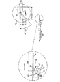
本願の図面のうち、本発明の結合部が図1及び図1aに示されており、本発明の改良点は図2及び図2aに、より明らかに示されている。本発明の結合部において、断面図で示された主ビームは天井格子において長手方向に延びている。同じコネクタ21及び22が、主ビーム20のウェブ25に設けられたスロット23に差し込まれており、相互結合している。コネクタ21及び22はそれぞれ28においてリベットによってクロスビーム26及び27に結合されている。
Of the drawings of the present application, the coupling portion of the present invention is shown in FIGS. 1 and 1a, and the improvements of the present invention are more clearly shown in FIGS. 2 and 2a. In the coupling part according to the invention, the main beam shown in cross-section extends in the longitudinal direction in the ceiling grid. The
結合部において、以下のことが生じる:
(1)コネクタ対コネクタ結合を形成するためにコネクタ21の端部30が爪31に係合し、コネクタ22の端部32が爪33に係合する;
(2)コネクタ21,22に設けられたロッキングラッチ40が非撓み位置を占めている;
(3)コネクタ21,22に設けられたバックストッパ35,36が、コネクタ対コネクタロックにおいて端部30,32を固定している
(4)この分野においてよく知られているように、コネクタ21,22はコネクタの断面形状によりスロット23内に水平方向及び垂直方向で拘束されている。ここまで記載された一般的な構成は、従来技術に対応している。
At the joint, the following occurs:
(1) The
(2) The
(3)
図1及び図1aに示された結合を形成する場合、引用した特許において、第1のコネクタ、すなわち同一であるそれぞれのコネクタ21又は22は、従来の形式でスロット23に押し込まれる又は差し込まれる。この説明では、まずコネクタ21がスロットに押し込まれると仮定する。
In forming the coupling shown in FIGS. 1 and 1a, in the cited patent, the first connector, ie each
ロッキングラッチ40が、一方向の移動において、スロット23の側部に接触し、十分に撓められ、これにより、ラッチ40はスロット23を通過し、静止位置へ戻るように復元される。この位置において、第1のコネクタ21がスロット23内に拘束される。
The locking
次いで、第2のコネクタ22が第1のコネクタ21に並んでスロット23に押し込まれる。再び、ロッキングラッチ40がスロット23の側部に接触するが、今度は、コネクタが既に挿入されているので、スロットの空間がより小さい。第2のコネクタ22は、スロット23に押し込まれると、ラッチがスロットを通過するまでラッチ40を閉鎖位置に向かって撓め、ラッチがスロットを通過した後、ラッチは静止位置へ撓んで開放する。コネクタ21,22は、図1に示したように、この時点でコネクタ対コネクタロックを形成し、この場合、爪31,33及びビーム端部30,32が撓められ、次いで休止位置においてロック位置へ復元される。
Next, the
これらの差込み式結合部において、第1のコネクタ21が挿入された後、第2のコネクタ、例えばコネクタ22が、着座した位置までスロット23を通過する時、以下のことが生じる:
(1)第2のコネクタ22はスロット23内で垂直方向で調整される
(2)第2のコネクタ22はスロット23の側部によって横方向に第1のコネクタに対して押し付けられる
(3)第2のコネクタ22に設けられたロッキングラッチ40がスロット23を通過するまで、このラッチ40はスロット23の側部によって閉鎖位置に向かって撓められ、次いでこのラッチは例えば図1に示したような静止位置に向かって跳ね返って開放する
(4)第1及び第2のコネクタ21及び22に設けられたロッキング爪31,33及びコネクタ端部30,32は、互いに接触すると撓められて離れる。
In these plug-in couplings, after the
(1) The
従来技術において、上の(1)〜(4)は重なり合う又は実質的に同時に発生し、これにより、結合部10を完成させるために必要とされる力及び作業は、すぐ上に言及された(1)、(2)、(3)及び(4)によって形成される個々の抵抗の合計を克服するために必要な力の合計のみならず、力(1)、(2)、(3)及び(4)が重なり合った又は同時に発生した場合に形成される摩擦を克服するための力及び作業でもある。これらの摩擦抵抗は、以下のことを含んでいた:
a.第2のコネクタ22がスロット23内において垂直に位置決めされる時の第2のコネクタ22のラッチ40とスロット23の側部との間の摩擦
b.コネクタ21,22のベースの間の横方向での摩擦
c.第2のコネクタ22がスロット23内において垂直に位置決めされるときの第2のコネクタ22の上部又は底部とスロット23の上側又は下側との間の摩擦
d.第2のコネクタ22がスロット23内において垂直に位置決めされるときの第1のコネクタ21と第2のコネクタ22との爪31及び33と端部30及び32との間の摩擦。
In the prior art, the above (1)-(4) overlap or occur substantially simultaneously, whereby the forces and operations required to complete the joint 10 were mentioned immediately above ( 1), (2), (3) and (4) as well as the sum of the forces required to overcome the sum of the individual resistances formed by (1), (2), (3) and (4) It is also the force and work to overcome the friction formed when (4) overlap or occur simultaneously. These frictional resistances included the following:
a. Friction between the
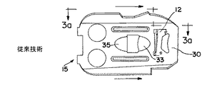
従来技術において、必要とされる合計の力及び作業を減じようとする試みにおいて、図3に示されたような従来のコネクタ15の前縁部におけるテーパ部37又はスロープは、緩やかな傾斜であり、これにより、第2のコネクタが垂直方向で調整されるときに、摩擦力が挿入長さの全体に分散されることができる。 In an attempt to reduce the total force and work required in the prior art, the taper 37 or slope at the leading edge of the conventional connector 15 as shown in FIG. This allows the frictional force to be distributed over the entire insertion length when the second connector is adjusted in the vertical direction.
本願発明の改良点は、上の摩擦(a)、(b)、(c)及び(d)による抵抗を克服するために必要な力と、本発明のロッキングラッチ40を閉鎖位置に向かって撓めるための上の(3)において必要な力と、コネクタ対コネクタインタロックを形成するために爪31及び33と端部30,32とを互いに対して撓めるための上の(4)において必要な力とを実質的に減じる。
The improvement of the present invention is that the force required to overcome the resistance due to the above friction (a), (b), (c) and (d) and the locking
従来技術のように、本願発明の改良点において、片持ちされた板ばねラッチ40は、例えば図2及び図2aに示されているように、コネクタベース39から打抜き加工によって形成されている。図3及び図3aに符号10で示された従来のラッチは、符号12において屈曲した、直線的なレバー11として形成されている。このラッチは、従来のコネクタ15のベース13に対して鋭角を形成している。
As in the prior art, in the improvement of the present invention, the cantilevered
本願発明の改良点において、図2及び図2aに示されたように本発明のラッチ40は、直線的なレバー状に延びる前は、例えば0.04インチ(1.01mm)の半径42を備えるように、ベース41から形成されている。本発明のラッチ40の直線的な部分43は、ベース41に対して約42゜の角度を形成している。ロッキングラッチ40におけるこのような湾曲は、第2のコネクタが符号47においてスロット23の側部に接触して、本発明のこのようなラッチ40によるスロット23の側部に対する抵抗を形成する前に、第2のコネクタ21又は22がスロット23に進入する距離46を増大する。本発明のこのような湾曲したロッキングラッチ40は、スロットを通過するときに閉鎖位置に向かって撓められるので、本発明のラッチ40がスロット23の側部と接触する距離48をも減じる。なぜならば、スロットは、従来の直線的なラッチよりもラッチの端部の近くにおいてラッチ40に接触するからである。
In an improvement of the present invention, as shown in FIGS. 2 and 2a, the
本発明のロッキングラッチ40のための代表的な寸法が図2aに示されている。
Representative dimensions for the locking
さらに、スロット23の側部との本発明のラッチ40の第1の接触は、本発明のラッチ40がベース41に結合されたラッチの箇所51から外れている。なぜならば、本発明のラッチ40の湾曲した部分の一部が、ベース41の平面において延びており、スロット23の側部による接触に曝されていないからである。箇所51は、図2aに示したように本発明のラッチ40の切断開始部及び湾曲開始部である。
Further, the first contact of the
したがって、本発明のラッチ40がスロットを通過するときにスロット23の側部によって加えられる力は、従来技術におけるよりも屈曲点51から離れて加えられ、ひいては、従来技術の直線的なレバーラッチ10よりも、本発明のラッチ40を撓めるために必要な力が小さい。なぜならば、力は、本発明のラッチが、結合部を形成するように押し込まれるときにスロット23の側部と衝突したときに、本発明のラッチ40におけるより大きな応力中心距離を有するからである。
Thus, the force applied by the side of the
従来技術においてラッチ10を撓めるために必要とされていたよりも、本発明のラッチ40を撓めるために、より短い距離に亘ってより小さな力が必要とされる。これにより、結合部を形成するために、著しくより少ない仕事が行われればよい。1つの結合部におけるこの有利な効果は、吊天井のための天井格子を形成する場合に必要とされる多くの結合部によって乗じられる。
Less force is required over a shorter distance to deflect the
本発明によって改良された結合部において、完全に挿入された時にコネクタがスロット23内において垂直方向で合致するように、コネクタを垂直方向で調整する必要がある。
In the improved joint according to the invention, it is necessary to adjust the connector in the vertical direction so that when fully inserted, the connector fits vertically in the
従来技術のラッチ10を撓めるために必要な力は大きく、コネクタの先端部の近くにおいて生じていたので、完全に挿入されたときにコネクタが垂直方向で所定の位置を占めるようにコネクタを完全に着座した位置に垂直方向で案内するテーパは、挿入のあらゆる1つの箇所において、付加された抵抗を制限するために、緩やかであった。
The force required to deflect the
したがって、コネクタ対コネクタインタロックが形成されており、爪が撓んでいる場合でさえも、テーパを急勾配ではなく緩やかであるように形成する必要性を考慮して、コネクタは依然として垂直方向で調整されており、さらに一層の抵抗を形成していた。 Therefore, even if the connector-to-connector interlock is formed and the pawl is flexed, the connector is still adjusted vertically to account for the need to form the taper to be gentle rather than steep It was forming even more resistance.
本発明において、コネクタ21,22の前縁におけるテーパ38は、比較的急勾配であるように、より急な角度で形成されており、これにより、相対的な迅速な調整が、コネクタがスロット23に挿入されるときにコネクタに対して垂直方向で行われる。より急勾配の迅速な調整は、通常、緩やかな挿入のものよりも大きな挿入力を必要とするにもかかわらず、より多くのではなく、より少ない力が必要とされる。この力の減少は、本発明のロッキングラッチ40がスロット23の側部と接触するのを遅らせることによって得られる。なぜならば、本発明のロッキングラッチから実質的に引きずり又は抵抗がないからである。
In the present invention, the
挿入時にスロット23内にコネクタを早期に垂直方向で位置決めすることによって得られる別の利点がある。本発明の第1及び第2のコネクタ20及び21の爪31及び33並びに端部30及び32が接触したとき、爪及び端部は、ロッキング位置への横方向でのこれらのエレメントの撓みに対する抵抗が最も小さい、垂直方向での相対的な位置を占めている。従来技術においては、接触が爪と端部との間に形成され、これらのエレメントの間に、これらのエレメントの最もフレキシブルな位置から中心がずれて力が加えられ、爪及び端部を撓めるために必要とされる力は、再び大きい。
There is another advantage gained by prematurely positioning the connector in the
図3及び図3aは従来のコネクタを示しているのに対し、図2及び図2aは、本発明の改良点を備えたコネクタを示している。 3 and 3a show a conventional connector, whereas FIGS. 2 and 2a show a connector with the improvements of the present invention.
図3及び図3aに示したように、直線的なレバー11の形式の従来のラッチ10は、従来のコネクタ15のベース13に対して鋭角に屈曲させられている。破線17は、従来のコネクタ15がスロット23に挿入された場合におけるスロット23の側部を拡大して示している。従来のコネクタ15は、従来のラッチ10の端部から距離18に位置する符号19の位置においてスロットの側部と衝突するまで、符号16で示された距離だけ前進する。
As shown in FIGS. 3 and 3 a, the
図2及び図2aには、本発明のラッチ40を備えた、本発明のコネクタ21と同じ、本発明のコネクタ22が示されている。再び、図3aに示したように、拡大した部分における破線17は、コネクタ22がスロット23に挿入された場合におけるスロット23の側部を示している。コネクタ22は、コネクタが符号47においてスロット23の側部に衝突する前に、距離46だけ前進する。これは、本発明のラッチ40の端部からの距離48である。
2 and 2a show the
従来技術に対する本発明の改良点の利点は、図4a、図4b及び図4cにグラフによって示されている。 The advantages of the improvements of the present invention over the prior art are illustrated graphically in FIGS. 4a, 4b and 4c.
図4a、図4b及び図4cを含む図4は、本発明の改良されたコネクタを用いた結合において生じる力と比較した、従来の結合において生じる抵抗を示している。 FIG. 4, which includes FIGS. 4a, 4b, and 4c, shows the resistance that occurs in a conventional connection compared to the force that occurs in a connection using the improved connector of the present invention.
従来技術において、80〜81までの線は、第2のコネクタをスロットに最初に挿入するときに生じる抵抗を示しているのに対し、ラッチは、スロット23の側部との初期接触から、抵抗が箇所81において約27ポンド(12.231kg)において最高点に到達するまで、撓められる。
In the prior art, the lines 80-81 indicate the resistance that occurs when the second connector is first inserted into the slot, while the latch is resistant from initial contact with the side of the
従来のラッチ10の直線的なレバー11の接触は、この行程の間比較的屈曲点12に近い。81において、符号82の時点までの行程中に、約10ポンド(4.53kg)までの抵抗の低下が生じる。従来の直線的なレバーラッチ10は、この低下の間、レバーがスロット23を通過するときに直線的なレバー11に沿ったより外側においてスロット23の側部に接触する。応力中心距離は、最初の接触時よりも長いので、必要な力はより小さい。
The contact of the linear lever 11 of the
符号82において、爪31及び33並びにコネクタ端部30及び32の撓みにより、再び抵抗が上昇し、この間に爪及びコネクタ端部はコネクタ対コネクタロックを形成している。抵抗は、符号83の箇所まで上昇し、この箇所においてコネクタ対コネクタロックが完了し、全てのエレメントは再び静止位置へ復元し、もはや抵抗又は運動は生じていない。
At 82, the resistance rises again due to flexing of the
本発明の改良点を備えた結合部を形成する場合に生じる抵抗を克服するために必要な力は、図4bにグラフによって示されている。本発明のラッチ40を有する第2のコネクタ22のスロット23内への同じ移動が、図4aに従来のコネクタに関して示されたように示されている。スロット23の側部との最初の接触は符号90において生じ、抵抗は、符号91における約14ポンド(6.342kg)まで上昇する。本発明のラッチ40がスロットを通過するときに、抵抗が極めて僅かに低下する。次いで、抵抗は符号93の時点における約16ポンド(7.248kg)まで上昇し、この間に爪31及び33並びにコネクタ端部30及び32が撓みながらコネクタ対コネクタロックが形成され、この後、符号94の時点で低下し、この時に全ての抵抗が終了し、コネクタ対コネクタロックが形成される。
The force required to overcome the resistance that occurs when forming a joint with the improvements of the present invention is illustrated graphically in FIG. 4b. The same movement of the
コネクタにおける本発明の改良点を備えることにより、結合部を形成する場合に、所要の力、及び力が加えられなければならない距離が明らかに著しく小さくなる。 By providing the improvements of the present invention in the connector, the required force and the distance that the force must be applied when forming the coupling is clearly significantly reduced.
図4cは図4a及び図4bのチャートを重ねて示しており、従来の結合部と本発明の結合部とのロックされる位置を、横軸に沿って重なり合った共通の点として符号94で示している。チャートにおけるΔXは、第2のコネクタがスロットに挿入される場合における、従来のラッチ15と本発明のラッチ40との、スロット23の側部17との接触時点の差を示している。やはり、図4cは、従来の結合部に比べて、本発明の結合部を形成するために必要な力及び仕事が著しく減じられていることをチャートの形式で示している。
FIG. 4c shows the charts of FIGS. 4a and 4b superimposed, and the position where the conventional joint and the joint of the present invention are locked is indicated by the
10 ラッチ、 11 レバー、 12 屈曲点、 13 ベース、 15 コネクタ、 20 主ビーム、 21,22 コネクタ、 23 スロット、 25 ウェブ、 26,27 クロスビーム、 28 リベット、 30 端部、 31 爪、 32 端部、 33 爪、 35,36 バックストッパ、 38 テーパ部、 40 ロッキングラッチ、 41 ベース、 42 半径、 51 屈曲点
10 Latch, 11 Lever, 12 Bending point, 13 Base, 15 Connector, 20 Main beam, 21, 22 Connector, 23 Slot, 25 Web, 26, 27 Cross beam, 28 Rivet, 30 End, 31 Claw, 32
Claims (8)
改良点が、ロッキングラッチがベースからアーチ状に屈曲していることを含むことを特徴とするコネクタ。 By being inserted into a slot provided in the main beam of the suspended ceiling grid, it locks with the same opposing connector already placed in the slot, and is integral with and from the base of the connector. In a connector having a bent, cantilevered locking latch,
The connector is characterized in that the improvement includes that the locking latch is bent in an arch shape from the base.
Applications Claiming Priority (2)
| Application Number | Priority Date | Filing Date | Title |
|---|---|---|---|
| US10/754,323 US7926238B2 (en) | 2004-01-09 | 2004-01-09 | Stab-in connector |
| US10/754323 | 2004-01-09 |
Publications (2)
| Publication Number | Publication Date |
|---|---|
| JP2005194873A JP2005194873A (en) | 2005-07-21 |
| JP4751069B2 true JP4751069B2 (en) | 2011-08-17 |
Family
ID=34592600
Family Applications (1)
| Application Number | Title | Priority Date | Filing Date |
|---|---|---|---|
| JP2005004543A Expired - Fee Related JP4751069B2 (en) | 2004-01-09 | 2005-01-11 | Plug-in connector |
Country Status (13)
| Country | Link |
|---|---|
| US (1) | US7926238B2 (en) |
| EP (1) | EP1553239B1 (en) |
| JP (1) | JP4751069B2 (en) |
| CN (1) | CN100523400C (en) |
| AT (1) | ATE408736T1 (en) |
| AU (1) | AU2004218724B2 (en) |
| CA (1) | CA2488594C (en) |
| DE (1) | DE602004016617D1 (en) |
| ES (1) | ES2312904T3 (en) |
| MX (1) | MXPA04012589A (en) |
| NZ (1) | NZ536057A (en) |
| PL (1) | PL1553239T3 (en) |
| RU (1) | RU2365715C2 (en) |
Families Citing this family (21)
| Publication number | Priority date | Publication date | Assignee | Title |
|---|---|---|---|---|
| NL1033867C2 (en) * | 2007-05-18 | 2008-11-20 | Bruinekool Yacht Support & Ind | Floor construction and method. |
| IT1399235B1 (en) * | 2010-04-06 | 2013-04-11 | Dallan Spa | PROFILE FOR HOUSINGS AND HOUSING |
| CN101845865A (en) * | 2010-04-29 | 2010-09-29 | 尉名杰 | Novel T-shaped plane butting keel |
| FR2966850B1 (en) * | 2010-10-29 | 2013-07-19 | Plafometal | CONNECTOR FOR SUSPENDED CEILING METAL FRAME AND CEILING USING SAME. |
| US8397462B2 (en) * | 2011-06-03 | 2013-03-19 | Usg Interiors, Llc | Open web grid runner |
| US8584418B2 (en) * | 2011-09-09 | 2013-11-19 | Usg Interiors, Llc | Cross runner connector and main runner receiving hole |
| US9151050B2 (en) | 2012-01-04 | 2015-10-06 | John Santeramo | Splice plate |
| DE202012003650U1 (en) | 2012-04-11 | 2012-07-17 | Plafometal | Connector for metal skeleton of a suspended ceiling and ceiling using this |
| DE202012003648U1 (en) | 2012-04-11 | 2012-06-21 | Plafometal | Metal skeleton for a suspended ceiling |
| US8839583B2 (en) | 2012-09-08 | 2014-09-23 | Worthington Armstrong Venture | Suspended ceiling grid adapter |
| US9482001B2 (en) | 2012-09-08 | 2016-11-01 | Worthington Armstrong Venture | Suspended ceiling grid adapter |
| US8869484B2 (en) * | 2012-11-13 | 2014-10-28 | Usg Interiors, Llc | Flexible drywall grid member for framing drywall structures |
| US20150085474A1 (en) * | 2013-09-20 | 2015-03-26 | Worthington Armstrong Venture | Beam support |
| CN104533004B (en) * | 2014-11-24 | 2016-12-07 | 浙江亚厦装饰股份有限公司 | A kind of grid for suspended ceiling |
| US9637918B1 (en) * | 2016-01-06 | 2017-05-02 | Usg Interiors, Llc | Cross runner to main runner anchor clip |
| CN121875421A (en) | 2016-09-08 | 2026-04-17 | 宝利格瑞德私人有限公司 | Components for suspending ceiling panels |
| RU2670812C9 (en) * | 2017-05-22 | 2018-11-28 | Дмитрий Владимирович Панга | Method for forming profile of given shape for stretch ceilings |
| RU175613U1 (en) * | 2017-08-17 | 2017-12-12 | Борис Алексеевич Адаменко | LOCK FOR JOINT CONNECTION OF T-SHAPES |
| CN108086569B (en) * | 2017-12-12 | 2019-11-15 | 广东爱富兰建设有限公司 | A kind of ceiling structure of stable connection |
| CA3076201A1 (en) * | 2019-04-03 | 2020-10-03 | Worthington Armstrong Venture | Splice plate with a cam lock |
| US11053682B1 (en) * | 2020-03-12 | 2021-07-06 | Usg Interiors, Llc | High strength main tee splice |
Family Cites Families (47)
| Publication number | Priority date | Publication date | Assignee | Title |
|---|---|---|---|---|
| US3193063A (en) * | 1962-05-18 | 1965-07-06 | Donn Prod Inc | Beam structure |
| US3312488A (en) * | 1964-04-14 | 1967-04-04 | Lickliter | Expansion joint and locking connection for supporting grid systems |
| US3321879A (en) * | 1964-08-05 | 1967-05-30 | W J Haertel & Co | Ceiling support structure with collapsible joint clip |
| US3354598A (en) * | 1965-07-30 | 1967-11-28 | Wood Conversion Co | Ventilating ceiling and suspension grid therefor |
| US3396997A (en) * | 1966-03-24 | 1968-08-13 | Rollform Inc | Fire-rated ceiling grid system |
| US3501185A (en) * | 1966-07-11 | 1970-03-17 | Donn Prod Inc | Cross beam connector |
| US3367695A (en) * | 1966-08-26 | 1968-02-06 | W J Haertel & Co | Ceiling suspension apparatus |
| US3584904A (en) * | 1969-03-13 | 1971-06-15 | Flangeklamp Corp | Locking connection for supporting grid systems |
| US3746379A (en) * | 1971-09-09 | 1973-07-17 | Flangeklamp Corp | Locking connection for supporting grid systems |
| US3979874A (en) * | 1972-11-24 | 1976-09-14 | Alabama Metal Industries Corporation | Suspended ceiling system and runner joints therefor |
| US3922829A (en) * | 1973-09-14 | 1975-12-02 | Roblin Hope S Ind Inc | Locking connection for supporting grid systems |
| USRE31201E (en) * | 1973-09-14 | 1983-04-12 | Donn Products Incorporated | Locking connection for supporting grid systems |
| US3921363A (en) * | 1974-05-17 | 1975-11-25 | Preston Metal & Roofing Prod | Cross member with end connector |
| US4108563A (en) * | 1975-10-24 | 1978-08-22 | Donn Products, Inc. | Locking connection for suspension ceiling systems |
| JPS52113513A (en) * | 1976-03-19 | 1977-09-22 | Roblin Industries | Connection lock device of structure |
| US4161856A (en) * | 1976-11-15 | 1979-07-24 | Donn Products, Inc. | Suspension ceiling system |
| US4106878A (en) * | 1977-02-04 | 1978-08-15 | National Rolling Mills Company | Fire-rated ceiling grid cross joint |
| US4314432A (en) * | 1980-03-17 | 1982-02-09 | Roper Corporation | Splice for beam in suspended ceiling system |
| US4317641A (en) * | 1980-05-05 | 1982-03-02 | Roblin Industries, Inc. | Locking connection for supporting grid systems |
| US4389828A (en) * | 1980-06-12 | 1983-06-28 | Howmet Aluminum Corp. | Suspended ceiling system with crossing clip |
| US4364686A (en) * | 1980-11-17 | 1982-12-21 | Lok Products Company | Locking device for grid system |
| US4499697A (en) * | 1981-02-09 | 1985-02-19 | Donn Incorporated | Suspended ceiling with removable tee sections |
| US4535580A (en) * | 1981-07-09 | 1985-08-20 | Donn Incorporated | Screw slot runner system |
| US4494350A (en) * | 1982-09-20 | 1985-01-22 | Ceiling Dynamics, Inc. | Aluminum suspension system |
| US4549383A (en) * | 1983-09-08 | 1985-10-29 | Chicago Metallic Corporation | Suspended ceiling grid system |
| US4525973A (en) * | 1984-01-09 | 1985-07-02 | Chicago Metallic Corporation | Suspended ceiling system |
| US4601153A (en) * | 1985-06-14 | 1986-07-22 | Chicago Metallic Corporation | Suspended ceiling system |
| US4621474A (en) * | 1985-07-25 | 1986-11-11 | Donn Incorporated | Grid connectors for suspension ceiling |
| US4611453A (en) * | 1985-07-25 | 1986-09-16 | Donn Incorporated | Suspension ceiling grid connectors |
| US4648230A (en) * | 1985-07-24 | 1987-03-10 | Donn Incorporated | Locking connection for suspension ceiling grid systems |
| US4712350A (en) * | 1986-05-16 | 1987-12-15 | Chicago Metallic Corporation | Centering arrangement for T members of a suspended ceiling |
| US4785603A (en) * | 1986-11-28 | 1988-11-22 | National Rolling Mills Inc. | Interlocking cross tee |
| US4827681A (en) * | 1986-11-28 | 1989-05-09 | National Rolling Mills, Inc. | Interlocking cross tee |
| US4779394B1 (en) * | 1987-04-14 | 1994-09-27 | Donn Inc | Connector for suspension ceiling grid |
| US4864791A (en) * | 1988-11-10 | 1989-09-12 | National Rolling Mills, Inc. | Fire strip |
| US4989387A (en) * | 1989-08-24 | 1991-02-05 | Chicago Metallic Corporation | Ceiling system with staked on connectors |
| US5044138A (en) * | 1989-10-13 | 1991-09-03 | Usg Interiors, Inc. | Ceiling suspension structure adapted for unopposed intersections |
| US6178712B1 (en) * | 1992-04-06 | 2001-01-30 | Worthington Armstrong Venture | Locking connection for ceiling grid system |
| US5271202A (en) * | 1992-05-12 | 1993-12-21 | Chicago Metallic Corporation | Suspended ceiling system with staked-on connectors |
| US5216865A (en) * | 1992-07-24 | 1993-06-08 | Usg Interiors, Inc. | Locking connector for suspension ceiling systems |
| US5517796A (en) * | 1994-05-25 | 1996-05-21 | Usg Interiors, Inc. | Stab-in removable end connector |
| US5839246A (en) * | 1996-09-12 | 1998-11-24 | Worthington Armstrong Venture | Grid framework for suspended ceiling |
| US5966887A (en) * | 1997-09-10 | 1999-10-19 | Bailey Metal Products Limited | Suspended ceiling cross tee end connector |
| US6305139B1 (en) * | 1998-08-01 | 2001-10-23 | Worthington Armstrong Venture | Beam clip |
| US6199343B1 (en) * | 1999-04-19 | 2001-03-13 | Worthington Armstrong Venture | Connector assembly for ceiling grid |
| US6523313B2 (en) * | 2001-03-06 | 2003-02-25 | Worthington Armstrong Venture | Main beam connection |
| US6729100B2 (en) * | 2002-04-30 | 2004-05-04 | Usg Interiors, Inc. | Main tee splice |
-
2004
- 2004-01-09 US US10/754,323 patent/US7926238B2/en not_active Expired - Lifetime
- 2004-10-12 AU AU2004218724A patent/AU2004218724B2/en not_active Ceased
- 2004-10-20 NZ NZ536057A patent/NZ536057A/en not_active IP Right Cessation
- 2004-11-11 EP EP04026847A patent/EP1553239B1/en not_active Expired - Lifetime
- 2004-11-11 ES ES04026847T patent/ES2312904T3/en not_active Expired - Lifetime
- 2004-11-11 AT AT04026847T patent/ATE408736T1/en not_active IP Right Cessation
- 2004-11-11 PL PL04026847T patent/PL1553239T3/en unknown
- 2004-11-11 DE DE602004016617T patent/DE602004016617D1/en not_active Expired - Lifetime
- 2004-11-30 CA CA2488594A patent/CA2488594C/en not_active Expired - Lifetime
- 2004-12-14 MX MXPA04012589A patent/MXPA04012589A/en active IP Right Grant
- 2004-12-31 CN CNB2004100818721A patent/CN100523400C/en not_active Expired - Fee Related
-
2005
- 2005-01-11 JP JP2005004543A patent/JP4751069B2/en not_active Expired - Fee Related
- 2005-01-11 RU RU2005100025/03A patent/RU2365715C2/en active
Also Published As
| Publication number | Publication date |
|---|---|
| CN1651678A (en) | 2005-08-10 |
| MXPA04012589A (en) | 2005-07-12 |
| US7926238B2 (en) | 2011-04-19 |
| ATE408736T1 (en) | 2008-10-15 |
| EP1553239A2 (en) | 2005-07-13 |
| US20050166509A1 (en) | 2005-08-04 |
| CA2488594A1 (en) | 2005-07-09 |
| NZ536057A (en) | 2006-06-30 |
| CN100523400C (en) | 2009-08-05 |
| AU2004218724A1 (en) | 2005-07-28 |
| DE602004016617D1 (en) | 2008-10-30 |
| JP2005194873A (en) | 2005-07-21 |
| EP1553239B1 (en) | 2008-09-17 |
| PL1553239T3 (en) | 2009-03-31 |
| RU2365715C2 (en) | 2009-08-27 |
| RU2005100025A (en) | 2006-06-20 |
| ES2312904T3 (en) | 2009-03-01 |
| EP1553239A3 (en) | 2006-06-28 |
| CA2488594C (en) | 2012-02-21 |
| AU2004218724B2 (en) | 2009-05-07 |
Similar Documents
| Publication | Publication Date | Title |
|---|---|---|
| JP4751069B2 (en) | Plug-in connector | |
| EP1239095B1 (en) | Main beam connection | |
| JP3872811B2 (en) | Suspended ceiling grid system | |
| DK1499780T3 (en) | SPLITING HEAD T-PIECES | |
| JP4482823B2 (en) | Terminal fitting | |
| US5839246A (en) | Grid framework for suspended ceiling | |
| EP2753768B1 (en) | Cross runner connector | |
| CN105008631B (en) | Supporting metal structure for the suspended ceiling | |
| EP4118278B1 (en) | Triple-lock main tee splice | |
| JPH10233251A (en) | Integrated contact spring | |
| RU2562308C2 (en) | Connecting clamp | |
| EP0287254B1 (en) | Connector for suspension ceiling grid | |
| JP6936141B2 (en) | Connection structure of sideways crossing members | |
| KR20180051034A (en) | Connecting Tool | |
| JP6604296B2 (en) | Connector mating method | |
| EP3497290B1 (en) | Hook connection clip for false ceiling system | |
| JP7820758B2 (en) | Wedge for connecting orthogonal pipes in greenhouses | |
| KR102325248B1 (en) | One touch rebar coupler with slide crimp | |
| JP4934495B2 (en) | Connecting mechanism for suspension plate for ceiling board | |
| WO2024030324A1 (en) | Light gauge main tee splice | |
| CN116921516A (en) | Steel pipe forming device |
Legal Events
| Date | Code | Title | Description |
|---|---|---|---|
| A621 | Written request for application examination |
Free format text: JAPANESE INTERMEDIATE CODE: A621 Effective date: 20080108 |
|
| A131 | Notification of reasons for refusal |
Free format text: JAPANESE INTERMEDIATE CODE: A131 Effective date: 20101015 |
|
| RD04 | Notification of resignation of power of attorney |
Free format text: JAPANESE INTERMEDIATE CODE: A7424 Effective date: 20101228 |
|
| A601 | Written request for extension of time |
Free format text: JAPANESE INTERMEDIATE CODE: A601 Effective date: 20110117 |
|
| A602 | Written permission of extension of time |
Free format text: JAPANESE INTERMEDIATE CODE: A602 Effective date: 20110120 |
|
| A601 | Written request for extension of time |
Free format text: JAPANESE INTERMEDIATE CODE: A601 Effective date: 20110215 |
|
| A602 | Written permission of extension of time |
Free format text: JAPANESE INTERMEDIATE CODE: A602 Effective date: 20110218 |
|
| A521 | Request for written amendment filed |
Free format text: JAPANESE INTERMEDIATE CODE: A523 Effective date: 20110315 |
|
| A01 | Written decision to grant a patent or to grant a registration (utility model) |
Free format text: JAPANESE INTERMEDIATE CODE: A01 Effective date: 20110511 |
|
| A01 | Written decision to grant a patent or to grant a registration (utility model) |
Free format text: JAPANESE INTERMEDIATE CODE: A01 |
|
| A61 | First payment of annual fees (during grant procedure) |
Free format text: JAPANESE INTERMEDIATE CODE: A61 Effective date: 20110520 |
|
| R150 | Certificate of patent or registration of utility model |
Free format text: JAPANESE INTERMEDIATE CODE: R150 |
|
| FPAY | Renewal fee payment (event date is renewal date of database) |
Free format text: PAYMENT UNTIL: 20140527 Year of fee payment: 3 |
|
| R250 | Receipt of annual fees |
Free format text: JAPANESE INTERMEDIATE CODE: R250 |
|
| R250 | Receipt of annual fees |
Free format text: JAPANESE INTERMEDIATE CODE: R250 |
|
| R250 | Receipt of annual fees |
Free format text: JAPANESE INTERMEDIATE CODE: R250 |
|
| LAPS | Cancellation because of no payment of annual fees |