EP1553239A2 - Stab-in connector - Google Patents
Stab-in connector Download PDFInfo
- Publication number
- EP1553239A2 EP1553239A2 EP04026847A EP04026847A EP1553239A2 EP 1553239 A2 EP1553239 A2 EP 1553239A2 EP 04026847 A EP04026847 A EP 04026847A EP 04026847 A EP04026847 A EP 04026847A EP 1553239 A2 EP1553239 A2 EP 1553239A2
- Authority
- EP
- European Patent Office
- Prior art keywords
- connector
- slot
- latch
- improvement
- delay
- Prior art date
- Legal status (The legal status is an assumption and is not a legal conclusion. Google has not performed a legal analysis and makes no representation as to the accuracy of the status listed.)
- Granted
Links
- 230000001934 delay Effects 0.000 abstract description 2
- 238000003780 insertion Methods 0.000 description 6
- 230000037431 insertion Effects 0.000 description 6
- 230000001154 acute effect Effects 0.000 description 4
- 230000011514 reflex Effects 0.000 description 3
- 239000002184 metal Substances 0.000 description 2
- 238000004080 punching Methods 0.000 description 2
- 230000000717 retained effect Effects 0.000 description 2
- 238000005452 bending Methods 0.000 description 1
- 230000009286 beneficial effect Effects 0.000 description 1
- 238000005520 cutting process Methods 0.000 description 1
- 230000003111 delayed effect Effects 0.000 description 1
- 230000000994 depressogenic effect Effects 0.000 description 1
- 238000004519 manufacturing process Methods 0.000 description 1
Images


Classifications
-
- E—FIXED CONSTRUCTIONS
- E04—BUILDING
- E04B—GENERAL BUILDING CONSTRUCTIONS; WALLS, e.g. PARTITIONS; ROOFS; FLOORS; CEILINGS; INSULATION OR OTHER PROTECTION OF BUILDINGS
- E04B9/00—Ceilings; Construction of ceilings, e.g. false ceilings; Ceiling construction with regard to insulation
- E04B9/06—Ceilings; Construction of ceilings, e.g. false ceilings; Ceiling construction with regard to insulation characterised by constructional features of the supporting construction, e.g. cross section or material of framework members
- E04B9/12—Connections between non-parallel members of the supporting construction
- E04B9/122—Connections between non-parallel members of the supporting construction one member passing through the other member, both members laying at least partly in the same plane
- E04B9/125—Connections between non-parallel members of the supporting construction one member passing through the other member, both members laying at least partly in the same plane both members being continuous members
-
- E—FIXED CONSTRUCTIONS
- E04—BUILDING
- E04B—GENERAL BUILDING CONSTRUCTIONS; WALLS, e.g. PARTITIONS; ROOFS; FLOORS; CEILINGS; INSULATION OR OTHER PROTECTION OF BUILDINGS
- E04B9/00—Ceilings; Construction of ceilings, e.g. false ceilings; Ceiling construction with regard to insulation
- E04B9/06—Ceilings; Construction of ceilings, e.g. false ceilings; Ceiling construction with regard to insulation characterised by constructional features of the supporting construction, e.g. cross section or material of framework members
- E04B9/065—Ceilings; Construction of ceilings, e.g. false ceilings; Ceiling construction with regard to insulation characterised by constructional features of the supporting construction, e.g. cross section or material of framework members comprising supporting beams having a folded cross-section
- E04B9/067—Ceilings; Construction of ceilings, e.g. false ceilings; Ceiling construction with regard to insulation characterised by constructional features of the supporting construction, e.g. cross section or material of framework members comprising supporting beams having a folded cross-section with inverted T-shaped cross-section
- E04B9/068—Ceilings; Construction of ceilings, e.g. false ceilings; Ceiling construction with regard to insulation characterised by constructional features of the supporting construction, e.g. cross section or material of framework members comprising supporting beams having a folded cross-section with inverted T-shaped cross-section with double web
Definitions
- Suspended ceilings are used extensively in commercial and industrial buildings.
- a metal grid framework of interconnected main beams and cross beams is hung from a structural ceiling by wires.
- the grid supports acoustical panels in rectangular openings formed in the grid.
- This invention relates to the connectors used in the grid to join a pair of opposing cross beams and a main beam at grid intersections.
- the grid in such ceilings has, at each grid intersection, a pair of opposing cross beams and a main beam that form a connection.
- the present invention relates to such a connection.
- Each cross beam in such a connection has a connector at its end that is thrust, or stabbed-in, from opposing sides of the main beam, through a slot in the main beam.
- the connectors are all identical.
- the connector that is first inserted into the slot is prevented from being withdrawn back out of the slot by the cantilevered latch in the connector, in the form of a pivoted flexible leaf spring.
- Such latch which is integral with the connector base and formed therefrom by punching, is biased toward an open position.
- the latch which is cantilevered at an angle from the base of the connector, flexes toward a closed position under the restraint of the side of the slot when the connector is stabbed through the slot to make the connection, but which then reflexes back to its biased rest position to prevent withdrawal of the connector back out of the slot.
- Another connector on an opposing cross beam identical to the first connector thrust through the slot, is then stabbed through the slot in the reduced space in the slot alongside the first.
- the latch on the connector contacts the side of the slot close to the latch pivot, and is flexed toward a closed position.
- Both connectors interconnect when the second connector into the slot is fully inserted.
- Detents formed from the connector base in the form of bulbs, that have a cam side and a locking side, and the ends of the connectors, flex and reflex to engage in what is sometimes referred to as a connector-to-connector lock, or "handshake" lock.
- a connector-to-connector lock or "handshake" lock.
- Such a "handshake" connection between the connectors prevents the connectors from being pulled apart lineally out of the slot.
- the connectors are kept laterally and vertically together by the slot in the main beam.
- the second connector In the seated locked position, the second connector is horizontally aligned with the first connector within the confines of the slot, so that the locking detents on the connectors are engaged and retained at the same level to form the connector-to-connector lock.
- the second connector must be either elevated or depressed as it passes into the slot to achieve such horizontal alignment.
- the profile of the leading edge of the connector is tapered to guide the connector during its travel through the main beam slot.
- the prior art stab-in connector described above is improved so that it takes much less force, and less work, to make the connection.
- the locking latch which in its unflexed position, must extend laterally far enough out from the base of the connector to prevent withdrawal of the first connector through the slot before the second connector is inserted, is pivoted from the connector base in an arc, rather than in an acute bend as in the prior art.
- the outward end of the locking latch in an unflexed position extends to the same position as the prior art straight latch pivoted at a sharp, acute angle. This position is necessary, so that the connector cannot be withdrawn after the latch passes through the slot.
- the second connector into the slot is being positioned vertically by the taper on the leading end of the connector, which engages either the top or bottom of the slot, to the same horizontal level as the first connector, without frictional resistance created in the connection of the prior art, where the locking latch, virtually immediately, forces the first and second connection laterally together.
- the second connector By adjusting the second connector into the slot more quickly vertically as it travels through the slot, the second connector, when the locking detents and connector ends engage in there by flexing, are in a position, as set forth in (3) above to offer the least resistance to flexing.
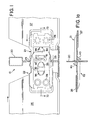
- FIG. 1a a connection of the invention is shown in Figures 1, 1a, with the improvement of the invention shown more clearly in Figure 2 and 2a.
- main beam 20 shown in cross section, extends longitudinally in a ceiling grid.
- Identical connectors 21 and 22 have been stabbed through a slot 23 in the web 25 of the main beam 20 and interconnect.
- the connectors 21 and 22 are connected respectively to cross beams 26 and 27 by rivets at 28. In the connection, the following occurs:
- a first connector either connector 21 or 22, both being identical, is thrust or stabbed through the slot 23 in the prior art manner. In this explanation, it will assume connector 21 is first thrust through the slot.
- Locking latch 40 contacts side of slot 23 and is flexed enough to allow the latch 40 to pass through slot 23 and reflex back to a rest position, in a one way movement. In this position, the first connector 21 through the slot is retained within the slot 23.
- the second connector 22 is then thrust through the slot 23 along side the first connector 21 through the slot 23. Again, locking latch 40 contacts side of slot 23, but now there is less room in the slot because a connector has already been inserted.
- the second connector 22 into the slot, as it is thrust through the slot 23, flexes the latch 40 toward a closed position, until the latch passes through the slot after which it flexes open to a rest position.
- the connectors 21 and 22 also form a connector-to-connector lock at this point, as seen in Figure 1, wherein the detents 31 and 33 and the beam ends 30 and 32 have flexed and then reflexed into a locked position, at rest.
- the present improvement reduces substantially the force necessary to overcome the resistance from the frictions (a), (b), (c) and (d) above and the forces necessary in (3) above to flex the locking latch 40 of the invention toward a closed position, and in (4) above to flex the detents 31 and 33 and ends 30 and 32 relative to one another to create the connector-to-connector interlock.
- the cantilevered leaf spring latch 40 continues to be formed, as by punching, from the connector base 39, as seen, for instance, in Figures 2 and 2a.
- the latch of the prior art, designated 10 as seen in Figures 3 and 3a, is in the form of a straight lever 11, pivoted at 12. It forms an acute sharp angle with the base 13 of prior art connector 15.
- the latch of the invention 40 is formed from the base 41 with a radius 42, for instance .04 inches, before extending in straight lever fashion.
- the straight portion 43 of the latch of the invention 40 forms an angle of about 429 with the base 41.
- Such a curve in locking latch 40 increases the distance 46 the second connector 21 or 22, enters into the slot 23 before it contacts the side of the slot 23 at 47 to create a resistance from such latch of the invention 40 against the side of the slot 23.
- Such a curved locking latch of the invention 40 also reduces the distance 48 the latch of the invention 40 is in contact with the side of the slot 23 as it is being flexed toward a closed position as it passes through the slot 23, since it contacts the latch 40 closer to the end of the latch than does prior art straight latch 10.
- the first contact of the latch of the invention 40 with the side of the slot 23 is further out from the point 51 of the latch of the invention 40 where it is joined to on the base 41, since part of the curved part of the latch of the invention 40 extends in the plane of the base 41 and is not exposed to contact by the side of the slot 23.
- Point 51 is the cutting start and the bending start of the latch of the invention 40 as seen in Figure 2a.
- connection improved by the present invention during the time the connector is being inserted, it is necessary to adjust the connector vertically, so that when fully inserted, the connector fits vertically into the slot 23 .
- the taper 38 at the leading edge of the connector 21, 22 is made relatively abrupt, at a steeper angle, so that a relative immediate adjustment is made vertically to the connector as it is being inserted into the slot 23. Even though a more steep, immediate adjustment would normally require a greater insertion force than that of a gradual insertion, there is less, rather than more force required. This reduction in force is obtained by the delayed contact of the locking latch of the invention 40 with the side of slot 23, since there is virtually no drag or resistance from the locking latch of the invention 40.
- Figures 3 and 3a show a prior art connector, while Figures 2 and 2a show a connector with the improvement of the invention.
- prior art latch 10 in the form of straight lever 11, is pivoted at an acute angle to base 13 of a prior art connector 15.
- Dotted line 17 represents, in the enlarged portion, the side of slot 23 as the connector 15 of the prior art is inserted into the slot 23.
- the prior art connector 15 travels the distance at 16 before it encounters the side of the slot at 19, which is at a distance 18 from the end of the prior art latch 10.
- FIGs 2 and 2a there is shown the connector of the invention 22, which is identical to the connector of the invention 21, with the latch of the invention 40.
- dotted line 17 in the enlarged portion represents the side of slot 23 as the connector 22 is inserted into the slot 23.
- the connector 22 travels the distance 46 before it encounters the side of the slot 23 at 47. This is a distance 48 from the end of the latch of the invention 40.
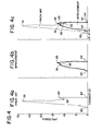
- Figure 4 shows the resistances encountered in a prior art connection compared to the forces encountered in a connection with the improved connector of the invention.
- the line from 80 to 81 represents the resistance encountered during the initial insertion of the second connector into the slot, while the latch 10 is being flexed from its initial contact with the side of the slot 23, until the resistance reaches its highest at about 27 pounds at point 81.
- Figure 4c overlaps the charts of Figures 4a and 4b with the locked position of the prior art connection, and the connection of the invention as an overlapped common point along the horizontal axis at 96.
- ⁇ X in the chart represent the distance of the delay in contact between the prior art latch 15, and the latch of the invention 40, with the side 17 of the slot 23, as the second connector into the slot is being inserted.
- Figure 4c, in chart form represents the substantial reduction in force, and work necessary to make the present connection, over that to make the prior art connection.
Landscapes
- Engineering & Computer Science (AREA)
- Architecture (AREA)
- Physics & Mathematics (AREA)
- Electromagnetism (AREA)
- Civil Engineering (AREA)
- Structural Engineering (AREA)
- Details Of Connecting Devices For Male And Female Coupling (AREA)
- Connector Housings Or Holding Contact Members (AREA)
- Mutual Connection Of Rods And Tubes (AREA)
- Insertion Pins And Rivets (AREA)
- Fats And Perfumes (AREA)
- Passenger Equipment (AREA)
- Ultra Sonic Daignosis Equipment (AREA)
Abstract
Description
and
Claims (9)
- In a connector that is stabbed through a slot in a main beam in a suspended ceiling grid to lock with an opposing identical connector already in the slot, and that has a cantilevered locking latch integral with and pivoted from a base in the connector;
the improvement comprising pivoting the locking latch from the base in an arc. - The improvement of claim 1, wherein the arc forms a radius of about .04 inches.
- The improvement of claim 1, wherein the locking latch constructed substantially in accordance with the dimensions shown in Figure 2a.
- The improvement of claim 1, wherein such improvement provides a delay in contact between the side of the slot and the locking latch, during which delay a taper on the connector being stabbed through the slot positions the connector vertically within the slot, more quickly than without the delay.
- The improvement of claim 1, wherein such improvement provides a delay in contact between the side of the slot and the locking latch, so that a greater lever arm is created to flex the locking latch as it is stabbed through the slot than would be created without the delay.
- The improvement of claim 1, wherein such improvement provides a delay in contact between the side of the slot and the locking latch, during which delay the lateral friction created between the connector already in the slot, and the connector that is being stabbed through the slot, is substantially reduced from said lateral friction created without the delay.
- The improvement of claim 1, wherein such improvement provides a delay in contact between the side of the slot and the locking latch, so that during the delay the connector being stabbed through the slot can be adjusted vertically to a position where it locks with the connector already in the slot.
- In combination, the improvements set forth in claims 1 through 7 above.
- A connector of claim 8 wherein substantially less force over a shorter distance is required with the improvements set forth in claim 8, to lock the connectors to each other and to the main beam, than is required without the improvements.
Priority Applications (1)
| Application Number | Priority Date | Filing Date | Title |
|---|---|---|---|
| PL04026847T PL1553239T3 (en) | 2004-01-09 | 2004-11-11 | Locking connector |
Applications Claiming Priority (2)
| Application Number | Priority Date | Filing Date | Title |
|---|---|---|---|
| US754323 | 2004-01-09 | ||
| US10/754,323 US7926238B2 (en) | 2004-01-09 | 2004-01-09 | Stab-in connector |
Publications (3)
| Publication Number | Publication Date |
|---|---|
| EP1553239A2 true EP1553239A2 (en) | 2005-07-13 |
| EP1553239A3 EP1553239A3 (en) | 2006-06-28 |
| EP1553239B1 EP1553239B1 (en) | 2008-09-17 |
Family
ID=34592600
Family Applications (1)
| Application Number | Title | Priority Date | Filing Date |
|---|---|---|---|
| EP04026847A Expired - Lifetime EP1553239B1 (en) | 2004-01-09 | 2004-11-11 | Locking connector |
Country Status (13)
| Country | Link |
|---|---|
| US (1) | US7926238B2 (en) |
| EP (1) | EP1553239B1 (en) |
| JP (1) | JP4751069B2 (en) |
| CN (1) | CN100523400C (en) |
| AT (1) | ATE408736T1 (en) |
| AU (1) | AU2004218724B2 (en) |
| CA (1) | CA2488594C (en) |
| DE (1) | DE602004016617D1 (en) |
| ES (1) | ES2312904T3 (en) |
| MX (1) | MXPA04012589A (en) |
| NZ (1) | NZ536057A (en) |
| PL (1) | PL1553239T3 (en) |
| RU (1) | RU2365715C2 (en) |
Cited By (5)
| Publication number | Priority date | Publication date | Assignee | Title |
|---|---|---|---|---|
| CN101845865A (en) * | 2010-04-29 | 2010-09-29 | 尉名杰 | Novel T-shaped plane butting keel |
| WO2012056127A1 (en) | 2010-10-29 | 2012-05-03 | Plafometal | Connector for suspended metal ceiling framework and ceiling employing same |
| DE202012003648U1 (en) | 2012-04-11 | 2012-06-21 | Plafometal | Metal skeleton for a suspended ceiling |
| DE202012003650U1 (en) | 2012-04-11 | 2012-07-17 | Plafometal | Connector for metal skeleton of a suspended ceiling and ceiling using this |
| US9151050B2 (en) | 2012-01-04 | 2015-10-06 | John Santeramo | Splice plate |
Families Citing this family (16)
| Publication number | Priority date | Publication date | Assignee | Title |
|---|---|---|---|---|
| NL1033867C2 (en) * | 2007-05-18 | 2008-11-20 | Bruinekool Yacht Support & Ind | Floor construction and method. |
| IT1399235B1 (en) * | 2010-04-06 | 2013-04-11 | Dallan Spa | PROFILE FOR HOUSINGS AND HOUSING |
| US8397462B2 (en) * | 2011-06-03 | 2013-03-19 | Usg Interiors, Llc | Open web grid runner |
| US8584418B2 (en) * | 2011-09-09 | 2013-11-19 | Usg Interiors, Llc | Cross runner connector and main runner receiving hole |
| US8839583B2 (en) | 2012-09-08 | 2014-09-23 | Worthington Armstrong Venture | Suspended ceiling grid adapter |
| US9482001B2 (en) | 2012-09-08 | 2016-11-01 | Worthington Armstrong Venture | Suspended ceiling grid adapter |
| US8869484B2 (en) * | 2012-11-13 | 2014-10-28 | Usg Interiors, Llc | Flexible drywall grid member for framing drywall structures |
| US20150085474A1 (en) * | 2013-09-20 | 2015-03-26 | Worthington Armstrong Venture | Beam support |
| CN104533004B (en) * | 2014-11-24 | 2016-12-07 | 浙江亚厦装饰股份有限公司 | A kind of grid for suspended ceiling |
| US9637918B1 (en) * | 2016-01-06 | 2017-05-02 | Usg Interiors, Llc | Cross runner to main runner anchor clip |
| WO2018045427A1 (en) | 2016-09-08 | 2018-03-15 | Polygrid Pty Ltd | Assemblies for suspending ceiling panels |
| RU2670812C9 (en) * | 2017-05-22 | 2018-11-28 | Дмитрий Владимирович Панга | Method for forming profile of given shape for stretch ceilings |
| RU175613U1 (en) * | 2017-08-17 | 2017-12-12 | Борис Алексеевич Адаменко | LOCK FOR JOINT CONNECTION OF T-SHAPES |
| CN108086569B (en) * | 2017-12-12 | 2019-11-15 | 广东爱富兰建设有限公司 | A kind of ceiling structure of stable connection |
| CA3076201A1 (en) * | 2019-04-03 | 2020-10-03 | Worthington Armstrong Venture | Splice plate with a cam lock |
| US11053682B1 (en) * | 2020-03-12 | 2021-07-06 | Usg Interiors, Llc | High strength main tee splice |
Family Cites Families (47)
| Publication number | Priority date | Publication date | Assignee | Title |
|---|---|---|---|---|
| US3193063A (en) | 1962-05-18 | 1965-07-06 | Donn Prod Inc | Beam structure |
| US3312488A (en) * | 1964-04-14 | 1967-04-04 | Lickliter | Expansion joint and locking connection for supporting grid systems |
| US3321879A (en) * | 1964-08-05 | 1967-05-30 | W J Haertel & Co | Ceiling support structure with collapsible joint clip |
| US3354598A (en) * | 1965-07-30 | 1967-11-28 | Wood Conversion Co | Ventilating ceiling and suspension grid therefor |
| US3396997A (en) | 1966-03-24 | 1968-08-13 | Rollform Inc | Fire-rated ceiling grid system |
| US3501185A (en) | 1966-07-11 | 1970-03-17 | Donn Prod Inc | Cross beam connector |
| US3367695A (en) | 1966-08-26 | 1968-02-06 | W J Haertel & Co | Ceiling suspension apparatus |
| US3584904A (en) * | 1969-03-13 | 1971-06-15 | Flangeklamp Corp | Locking connection for supporting grid systems |
| US3746379A (en) * | 1971-09-09 | 1973-07-17 | Flangeklamp Corp | Locking connection for supporting grid systems |
| US3979874A (en) * | 1972-11-24 | 1976-09-14 | Alabama Metal Industries Corporation | Suspended ceiling system and runner joints therefor |
| USRE31201E (en) * | 1973-09-14 | 1983-04-12 | Donn Products Incorporated | Locking connection for supporting grid systems |
| US3922829A (en) | 1973-09-14 | 1975-12-02 | Roblin Hope S Ind Inc | Locking connection for supporting grid systems |
| US3921363A (en) * | 1974-05-17 | 1975-11-25 | Preston Metal & Roofing Prod | Cross member with end connector |
| US4108563A (en) * | 1975-10-24 | 1978-08-22 | Donn Products, Inc. | Locking connection for suspension ceiling systems |
| JPS52113513A (en) * | 1976-03-19 | 1977-09-22 | Roblin Industries | Connection lock device of structure |
| US4161856A (en) * | 1976-11-15 | 1979-07-24 | Donn Products, Inc. | Suspension ceiling system |
| US4106878A (en) | 1977-02-04 | 1978-08-15 | National Rolling Mills Company | Fire-rated ceiling grid cross joint |
| US4314432A (en) * | 1980-03-17 | 1982-02-09 | Roper Corporation | Splice for beam in suspended ceiling system |
| US4317641A (en) * | 1980-05-05 | 1982-03-02 | Roblin Industries, Inc. | Locking connection for supporting grid systems |
| US4389828A (en) * | 1980-06-12 | 1983-06-28 | Howmet Aluminum Corp. | Suspended ceiling system with crossing clip |
| US4364686A (en) | 1980-11-17 | 1982-12-21 | Lok Products Company | Locking device for grid system |
| US4499697A (en) | 1981-02-09 | 1985-02-19 | Donn Incorporated | Suspended ceiling with removable tee sections |
| US4535580A (en) | 1981-07-09 | 1985-08-20 | Donn Incorporated | Screw slot runner system |
| US4494350A (en) * | 1982-09-20 | 1985-01-22 | Ceiling Dynamics, Inc. | Aluminum suspension system |
| US4549383A (en) | 1983-09-08 | 1985-10-29 | Chicago Metallic Corporation | Suspended ceiling grid system |
| US4525973A (en) * | 1984-01-09 | 1985-07-02 | Chicago Metallic Corporation | Suspended ceiling system |
| US4601153A (en) * | 1985-06-14 | 1986-07-22 | Chicago Metallic Corporation | Suspended ceiling system |
| US4611453A (en) * | 1985-07-25 | 1986-09-16 | Donn Incorporated | Suspension ceiling grid connectors |
| US4648230A (en) | 1985-07-24 | 1987-03-10 | Donn Incorporated | Locking connection for suspension ceiling grid systems |
| US4621474A (en) | 1985-07-25 | 1986-11-11 | Donn Incorporated | Grid connectors for suspension ceiling |
| US4712350A (en) | 1986-05-16 | 1987-12-15 | Chicago Metallic Corporation | Centering arrangement for T members of a suspended ceiling |
| US4827681A (en) | 1986-11-28 | 1989-05-09 | National Rolling Mills, Inc. | Interlocking cross tee |
| US4785603A (en) * | 1986-11-28 | 1988-11-22 | National Rolling Mills Inc. | Interlocking cross tee |
| US4779394B1 (en) | 1987-04-14 | 1994-09-27 | Donn Inc | Connector for suspension ceiling grid |
| US4864791A (en) | 1988-11-10 | 1989-09-12 | National Rolling Mills, Inc. | Fire strip |
| US4989387A (en) * | 1989-08-24 | 1991-02-05 | Chicago Metallic Corporation | Ceiling system with staked on connectors |
| US5044138A (en) | 1989-10-13 | 1991-09-03 | Usg Interiors, Inc. | Ceiling suspension structure adapted for unopposed intersections |
| US6178712B1 (en) | 1992-04-06 | 2001-01-30 | Worthington Armstrong Venture | Locking connection for ceiling grid system |
| US5271202A (en) * | 1992-05-12 | 1993-12-21 | Chicago Metallic Corporation | Suspended ceiling system with staked-on connectors |
| US5216865A (en) | 1992-07-24 | 1993-06-08 | Usg Interiors, Inc. | Locking connector for suspension ceiling systems |
| US5517796A (en) | 1994-05-25 | 1996-05-21 | Usg Interiors, Inc. | Stab-in removable end connector |
| US5839246A (en) * | 1996-09-12 | 1998-11-24 | Worthington Armstrong Venture | Grid framework for suspended ceiling |
| US5966887A (en) * | 1997-09-10 | 1999-10-19 | Bailey Metal Products Limited | Suspended ceiling cross tee end connector |
| US6305139B1 (en) * | 1998-08-01 | 2001-10-23 | Worthington Armstrong Venture | Beam clip |
| US6199343B1 (en) * | 1999-04-19 | 2001-03-13 | Worthington Armstrong Venture | Connector assembly for ceiling grid |
| US6523313B2 (en) * | 2001-03-06 | 2003-02-25 | Worthington Armstrong Venture | Main beam connection |
| US6729100B2 (en) * | 2002-04-30 | 2004-05-04 | Usg Interiors, Inc. | Main tee splice |
-
2004
- 2004-01-09 US US10/754,323 patent/US7926238B2/en not_active Expired - Lifetime
- 2004-10-12 AU AU2004218724A patent/AU2004218724B2/en not_active Ceased
- 2004-10-20 NZ NZ536057A patent/NZ536057A/en not_active IP Right Cessation
- 2004-11-11 PL PL04026847T patent/PL1553239T3/en unknown
- 2004-11-11 EP EP04026847A patent/EP1553239B1/en not_active Expired - Lifetime
- 2004-11-11 ES ES04026847T patent/ES2312904T3/en not_active Expired - Lifetime
- 2004-11-11 AT AT04026847T patent/ATE408736T1/en not_active IP Right Cessation
- 2004-11-11 DE DE602004016617T patent/DE602004016617D1/en not_active Expired - Lifetime
- 2004-11-30 CA CA2488594A patent/CA2488594C/en not_active Expired - Lifetime
- 2004-12-14 MX MXPA04012589A patent/MXPA04012589A/en active IP Right Grant
- 2004-12-31 CN CNB2004100818721A patent/CN100523400C/en not_active Expired - Fee Related
-
2005
- 2005-01-11 JP JP2005004543A patent/JP4751069B2/en not_active Expired - Fee Related
- 2005-01-11 RU RU2005100025/03A patent/RU2365715C2/en active
Cited By (6)
| Publication number | Priority date | Publication date | Assignee | Title |
|---|---|---|---|---|
| CN101845865A (en) * | 2010-04-29 | 2010-09-29 | 尉名杰 | Novel T-shaped plane butting keel |
| WO2012056127A1 (en) | 2010-10-29 | 2012-05-03 | Plafometal | Connector for suspended metal ceiling framework and ceiling employing same |
| EP2957687A1 (en) | 2010-10-29 | 2015-12-23 | Plafometal | Metal supporting frame for ceiling |
| US9151050B2 (en) | 2012-01-04 | 2015-10-06 | John Santeramo | Splice plate |
| DE202012003648U1 (en) | 2012-04-11 | 2012-06-21 | Plafometal | Metal skeleton for a suspended ceiling |
| DE202012003650U1 (en) | 2012-04-11 | 2012-07-17 | Plafometal | Connector for metal skeleton of a suspended ceiling and ceiling using this |
Also Published As
| Publication number | Publication date |
|---|---|
| JP4751069B2 (en) | 2011-08-17 |
| JP2005194873A (en) | 2005-07-21 |
| NZ536057A (en) | 2006-06-30 |
| PL1553239T3 (en) | 2009-03-31 |
| EP1553239A3 (en) | 2006-06-28 |
| EP1553239B1 (en) | 2008-09-17 |
| RU2005100025A (en) | 2006-06-20 |
| DE602004016617D1 (en) | 2008-10-30 |
| CN1651678A (en) | 2005-08-10 |
| US7926238B2 (en) | 2011-04-19 |
| MXPA04012589A (en) | 2005-07-12 |
| CA2488594A1 (en) | 2005-07-09 |
| RU2365715C2 (en) | 2009-08-27 |
| CN100523400C (en) | 2009-08-05 |
| AU2004218724B2 (en) | 2009-05-07 |
| US20050166509A1 (en) | 2005-08-04 |
| ES2312904T3 (en) | 2009-03-01 |
| ATE408736T1 (en) | 2008-10-15 |
| CA2488594C (en) | 2012-02-21 |
| AU2004218724A1 (en) | 2005-07-28 |
Similar Documents
| Publication | Publication Date | Title |
|---|---|---|
| EP1553239B1 (en) | Locking connector | |
| JP3872811B2 (en) | Suspended ceiling grid system | |
| US5839246A (en) | Grid framework for suspended ceiling | |
| CA2481722C (en) | Main tee splice | |
| JP3745778B2 (en) | Lattice connector | |
| RU2233954C2 (en) | Connection device for main beams of suspended ceiling connection | |
| EP4118278B1 (en) | Triple-lock main tee splice | |
| EP0287254B1 (en) | Connector for suspension ceiling grid | |
| EP1640523A2 (en) | Stab-in connector with expansion relief | |
| RU2821487C1 (en) | High-strength main tee joint | |
| JP2015021347A (en) | Ceiling reinforcement metal fitting | |
| MXPA98002535A (en) | Grid connector |
Legal Events
| Date | Code | Title | Description |
|---|---|---|---|
| PUAI | Public reference made under article 153(3) epc to a published international application that has entered the european phase |
Free format text: ORIGINAL CODE: 0009012 |
|
| AK | Designated contracting states |
Kind code of ref document: A2 Designated state(s): AT BE BG CH CY CZ DE DK EE ES FI FR GB GR HU IE IS IT LI LU MC NL PL PT RO SE SI SK TR |
|
| AX | Request for extension of the european patent |
Extension state: AL HR LT LV MK YU |
|
| PUAL | Search report despatched |
Free format text: ORIGINAL CODE: 0009013 |
|
| AK | Designated contracting states |
Kind code of ref document: A3 Designated state(s): AT BE BG CH CY CZ DE DK EE ES FI FR GB GR HU IE IS IT LI LU MC NL PL PT RO SE SI SK TR |
|
| AX | Request for extension of the european patent |
Extension state: AL HR LT LV MK YU |
|
| 17P | Request for examination filed |
Effective date: 20060726 |
|
| R17C | First examination report despatched (corrected) |
Effective date: 20061005 |
|
| AKX | Designation fees paid |
Designated state(s): AT BE BG CH CY CZ DE DK EE ES FI FR GB GR HU IE IS IT LI LU MC NL PL PT RO SE SI SK TR |
|
| 17Q | First examination report despatched |
Effective date: 20061005 |
|
| GRAP | Despatch of communication of intention to grant a patent |
Free format text: ORIGINAL CODE: EPIDOSNIGR1 |
|
| GRAS | Grant fee paid |
Free format text: ORIGINAL CODE: EPIDOSNIGR3 |
|
| GRAA | (expected) grant |
Free format text: ORIGINAL CODE: 0009210 |
|
| AK | Designated contracting states |
Kind code of ref document: B1 Designated state(s): AT BE BG CH CY CZ DE DK EE ES FI FR GB GR HU IE IS IT LI LU MC NL PL PT RO SE SI SK TR |
|
| REG | Reference to a national code |
Ref country code: GB Ref legal event code: FG4D |
|
| REG | Reference to a national code |
Ref country code: CH Ref legal event code: EP |
|
| REG | Reference to a national code |
Ref country code: IE Ref legal event code: FG4D |
|
| REF | Corresponds to: |
Ref document number: 602004016617 Country of ref document: DE Date of ref document: 20081030 Kind code of ref document: P |
|
| PG25 | Lapsed in a contracting state [announced via postgrant information from national office to epo] |
Ref country code: SI Free format text: LAPSE BECAUSE OF FAILURE TO SUBMIT A TRANSLATION OF THE DESCRIPTION OR TO PAY THE FEE WITHIN THE PRESCRIBED TIME-LIMIT Effective date: 20080917 Ref country code: FI Free format text: LAPSE BECAUSE OF FAILURE TO SUBMIT A TRANSLATION OF THE DESCRIPTION OR TO PAY THE FEE WITHIN THE PRESCRIBED TIME-LIMIT Effective date: 20080917 Ref country code: AT Free format text: LAPSE BECAUSE OF FAILURE TO SUBMIT A TRANSLATION OF THE DESCRIPTION OR TO PAY THE FEE WITHIN THE PRESCRIBED TIME-LIMIT Effective date: 20080917 |
|
| REG | Reference to a national code |
Ref country code: ES Ref legal event code: FG2A Ref document number: 2312904 Country of ref document: ES Kind code of ref document: T3 |
|
| REG | Reference to a national code |
Ref country code: PL Ref legal event code: T3 |
|
| PG25 | Lapsed in a contracting state [announced via postgrant information from national office to epo] |
Ref country code: BG Free format text: LAPSE BECAUSE OF FAILURE TO SUBMIT A TRANSLATION OF THE DESCRIPTION OR TO PAY THE FEE WITHIN THE PRESCRIBED TIME-LIMIT Effective date: 20081217 |
|
| PG25 | Lapsed in a contracting state [announced via postgrant information from national office to epo] |
Ref country code: IS Free format text: LAPSE BECAUSE OF FAILURE TO SUBMIT A TRANSLATION OF THE DESCRIPTION OR TO PAY THE FEE WITHIN THE PRESCRIBED TIME-LIMIT Effective date: 20090117 Ref country code: CZ Free format text: LAPSE BECAUSE OF FAILURE TO SUBMIT A TRANSLATION OF THE DESCRIPTION OR TO PAY THE FEE WITHIN THE PRESCRIBED TIME-LIMIT Effective date: 20080917 Ref country code: PT Free format text: LAPSE BECAUSE OF FAILURE TO SUBMIT A TRANSLATION OF THE DESCRIPTION OR TO PAY THE FEE WITHIN THE PRESCRIBED TIME-LIMIT Effective date: 20090217 Ref country code: SK Free format text: LAPSE BECAUSE OF FAILURE TO SUBMIT A TRANSLATION OF THE DESCRIPTION OR TO PAY THE FEE WITHIN THE PRESCRIBED TIME-LIMIT Effective date: 20080917 Ref country code: RO Free format text: LAPSE BECAUSE OF FAILURE TO SUBMIT A TRANSLATION OF THE DESCRIPTION OR TO PAY THE FEE WITHIN THE PRESCRIBED TIME-LIMIT Effective date: 20080917 |
|
| PG25 | Lapsed in a contracting state [announced via postgrant information from national office to epo] |
Ref country code: MC Free format text: LAPSE BECAUSE OF NON-PAYMENT OF DUE FEES Effective date: 20081130 |
|
| REG | Reference to a national code |
Ref country code: CH Ref legal event code: PL |
|
| PLBE | No opposition filed within time limit |
Free format text: ORIGINAL CODE: 0009261 |
|
| STAA | Information on the status of an ep patent application or granted ep patent |
Free format text: STATUS: NO OPPOSITION FILED WITHIN TIME LIMIT |
|
| PG25 | Lapsed in a contracting state [announced via postgrant information from national office to epo] |
Ref country code: EE Free format text: LAPSE BECAUSE OF FAILURE TO SUBMIT A TRANSLATION OF THE DESCRIPTION OR TO PAY THE FEE WITHIN THE PRESCRIBED TIME-LIMIT Effective date: 20080917 Ref country code: DK Free format text: LAPSE BECAUSE OF FAILURE TO SUBMIT A TRANSLATION OF THE DESCRIPTION OR TO PAY THE FEE WITHIN THE PRESCRIBED TIME-LIMIT Effective date: 20080917 |
|
| REG | Reference to a national code |
Ref country code: IE Ref legal event code: MM4A |
|
| 26N | No opposition filed |
Effective date: 20090618 |
|
| PG25 | Lapsed in a contracting state [announced via postgrant information from national office to epo] |
Ref country code: LI Free format text: LAPSE BECAUSE OF NON-PAYMENT OF DUE FEES Effective date: 20081130 Ref country code: IE Free format text: LAPSE BECAUSE OF NON-PAYMENT OF DUE FEES Effective date: 20081111 Ref country code: CH Free format text: LAPSE BECAUSE OF NON-PAYMENT OF DUE FEES Effective date: 20081130 |
|
| PG25 | Lapsed in a contracting state [announced via postgrant information from national office to epo] |
Ref country code: SE Free format text: LAPSE BECAUSE OF FAILURE TO SUBMIT A TRANSLATION OF THE DESCRIPTION OR TO PAY THE FEE WITHIN THE PRESCRIBED TIME-LIMIT Effective date: 20081217 |
|
| PG25 | Lapsed in a contracting state [announced via postgrant information from national office to epo] |
Ref country code: CY Free format text: LAPSE BECAUSE OF FAILURE TO SUBMIT A TRANSLATION OF THE DESCRIPTION OR TO PAY THE FEE WITHIN THE PRESCRIBED TIME-LIMIT Effective date: 20080917 Ref country code: HU Free format text: LAPSE BECAUSE OF FAILURE TO SUBMIT A TRANSLATION OF THE DESCRIPTION OR TO PAY THE FEE WITHIN THE PRESCRIBED TIME-LIMIT Effective date: 20090318 Ref country code: LU Free format text: LAPSE BECAUSE OF NON-PAYMENT OF DUE FEES Effective date: 20081111 |
|
| PG25 | Lapsed in a contracting state [announced via postgrant information from national office to epo] |
Ref country code: TR Free format text: LAPSE BECAUSE OF FAILURE TO SUBMIT A TRANSLATION OF THE DESCRIPTION OR TO PAY THE FEE WITHIN THE PRESCRIBED TIME-LIMIT Effective date: 20080917 |
|
| PG25 | Lapsed in a contracting state [announced via postgrant information from national office to epo] |
Ref country code: GR Free format text: LAPSE BECAUSE OF FAILURE TO SUBMIT A TRANSLATION OF THE DESCRIPTION OR TO PAY THE FEE WITHIN THE PRESCRIBED TIME-LIMIT Effective date: 20081218 |
|
| PGFP | Annual fee paid to national office [announced via postgrant information from national office to epo] |
Ref country code: ES Payment date: 20131011 Year of fee payment: 10 Ref country code: NL Payment date: 20131109 Year of fee payment: 10 |
|
| REG | Reference to a national code |
Ref country code: NL Ref legal event code: V1 Effective date: 20150601 |
|
| PG25 | Lapsed in a contracting state [announced via postgrant information from national office to epo] |
Ref country code: NL Free format text: LAPSE BECAUSE OF NON-PAYMENT OF DUE FEES Effective date: 20150601 |
|
| REG | Reference to a national code |
Ref country code: FR Ref legal event code: PLFP Year of fee payment: 12 |
|
| REG | Reference to a national code |
Ref country code: ES Ref legal event code: FD2A Effective date: 20151229 |
|
| PG25 | Lapsed in a contracting state [announced via postgrant information from national office to epo] |
Ref country code: ES Free format text: LAPSE BECAUSE OF NON-PAYMENT OF DUE FEES Effective date: 20141112 |
|
| REG | Reference to a national code |
Ref country code: FR Ref legal event code: PLFP Year of fee payment: 13 |
|
| REG | Reference to a national code |
Ref country code: FR Ref legal event code: PLFP Year of fee payment: 14 |
|
| PGFP | Annual fee paid to national office [announced via postgrant information from national office to epo] |
Ref country code: IT Payment date: 20221123 Year of fee payment: 19 Ref country code: GB Payment date: 20221128 Year of fee payment: 19 Ref country code: FR Payment date: 20221123 Year of fee payment: 19 Ref country code: DE Payment date: 20221125 Year of fee payment: 19 |
|
| PGFP | Annual fee paid to national office [announced via postgrant information from national office to epo] |
Ref country code: PL Payment date: 20221026 Year of fee payment: 19 Ref country code: BE Payment date: 20221128 Year of fee payment: 19 |
|
| REG | Reference to a national code |
Ref country code: DE Ref legal event code: R119 Ref document number: 602004016617 Country of ref document: DE |
|
| GBPC | Gb: european patent ceased through non-payment of renewal fee |
Effective date: 20231111 |
|
| REG | Reference to a national code |
Ref country code: BE Ref legal event code: MM Effective date: 20231130 |
|
| PG25 | Lapsed in a contracting state [announced via postgrant information from national office to epo] |
Ref country code: DE Free format text: LAPSE BECAUSE OF NON-PAYMENT OF DUE FEES Effective date: 20240601 |
|
| PG25 | Lapsed in a contracting state [announced via postgrant information from national office to epo] |
Ref country code: GB Free format text: LAPSE BECAUSE OF NON-PAYMENT OF DUE FEES Effective date: 20231111 |
|
| PG25 | Lapsed in a contracting state [announced via postgrant information from national office to epo] |
Ref country code: BE Free format text: LAPSE BECAUSE OF NON-PAYMENT OF DUE FEES Effective date: 20231130 |
|
| PG25 | Lapsed in a contracting state [announced via postgrant information from national office to epo] |
Ref country code: FR Free format text: LAPSE BECAUSE OF NON-PAYMENT OF DUE FEES Effective date: 20231130 |
|
| PG25 | Lapsed in a contracting state [announced via postgrant information from national office to epo] |
Ref country code: GB Free format text: LAPSE BECAUSE OF NON-PAYMENT OF DUE FEES Effective date: 20231111 Ref country code: FR Free format text: LAPSE BECAUSE OF NON-PAYMENT OF DUE FEES Effective date: 20231130 Ref country code: DE Free format text: LAPSE BECAUSE OF NON-PAYMENT OF DUE FEES Effective date: 20240601 Ref country code: BE Free format text: LAPSE BECAUSE OF NON-PAYMENT OF DUE FEES Effective date: 20231130 |
|
| PG25 | Lapsed in a contracting state [announced via postgrant information from national office to epo] |
Ref country code: IT Free format text: LAPSE BECAUSE OF NON-PAYMENT OF DUE FEES Effective date: 20231111 |
|
| PG25 | Lapsed in a contracting state [announced via postgrant information from national office to epo] |
Ref country code: IT Free format text: LAPSE BECAUSE OF NON-PAYMENT OF DUE FEES Effective date: 20231111 |
|
| PG25 | Lapsed in a contracting state [announced via postgrant information from national office to epo] |
Ref country code: PL Free format text: LAPSE BECAUSE OF NON-PAYMENT OF DUE FEES Effective date: 20231111 |