JP4750913B2 - Method and apparatus for applying a pattern on a support means - Google Patents
Method and apparatus for applying a pattern on a support means Download PDFInfo
- Publication number
- JP4750913B2 JP4750913B2 JP50056399A JP50056399A JP4750913B2 JP 4750913 B2 JP4750913 B2 JP 4750913B2 JP 50056399 A JP50056399 A JP 50056399A JP 50056399 A JP50056399 A JP 50056399A JP 4750913 B2 JP4750913 B2 JP 4750913B2
- Authority
- JP
- Japan
- Prior art keywords
- laminate
- pattern
- press roll
- layer
- sticking
- Prior art date
- Legal status (The legal status is an assumption and is not a legal conclusion. Google has not performed a legal analysis and makes no representation as to the accuracy of the status listed.)
- Expired - Lifetime
Links
Images


Classifications
-
- B—PERFORMING OPERATIONS; TRANSPORTING
- B32—LAYERED PRODUCTS
- B32B—LAYERED PRODUCTS, i.e. PRODUCTS BUILT-UP OF STRATA OF FLAT OR NON-FLAT, e.g. CELLULAR OR HONEYCOMB, FORM
- B32B37/00—Methods or apparatus for laminating, e.g. by curing or by ultrasonic bonding
- B32B37/0046—Methods or apparatus for laminating, e.g. by curing or by ultrasonic bonding characterised by constructional aspects of the apparatus
-
- B—PERFORMING OPERATIONS; TRANSPORTING
- B32—LAYERED PRODUCTS
- B32B—LAYERED PRODUCTS, i.e. PRODUCTS BUILT-UP OF STRATA OF FLAT OR NON-FLAT, e.g. CELLULAR OR HONEYCOMB, FORM
- B32B38/00—Ancillary operations in connection with laminating processes
- B32B38/18—Handling of layers or the laminate
- B32B38/1825—Handling of layers or the laminate characterised by the control or constructional features of devices for tensioning, stretching or registration
- B32B38/1833—Positioning, e.g. registration or centering
- B32B38/1841—Positioning, e.g. registration or centering during laying up
- B32B38/185—Positioning, e.g. registration or centering during laying up combined with the cutting of one or more layers
-
- B—PERFORMING OPERATIONS; TRANSPORTING
- B44—DECORATIVE ARTS
- B44C—PRODUCING DECORATIVE EFFECTS; MOSAICS; TARSIA WORK; PAPERHANGING
- B44C1/00—Processes, not specifically provided for elsewhere, for producing decorative surface effects
- B44C1/16—Processes, not specifically provided for elsewhere, for producing decorative surface effects for applying transfer pictures or the like
- B44C1/162—Decalcomanias with a transfer layer comprising indicia with definite outlines such as letters and with means facilitating the desired fitting to the permanent base
Abstract
Description
【0001】
【技術分野】
本発明は、標識の支持手段上へ予め定められたパターンを付ける方法に関し、前記パターンは、標識の上に装飾及び/又は情報を形成するためのものであり、パターン層とキャリア層を、これらを結合する接着層とともに含む箔を利用し、上記パターンに含まれる部分は、予め定められたパターンに従って予めプログラムされる電子制御ユニットによって制御される切断装置の手段により箔のパターン層において切り出され、その後、箔がパターン層が上方に面した状態で、パターン付け装置内の平坦配置面を有するラミネート接合テーブル上に配設される方法に関する。
【0002】
【背景技術】
また、本発明は、標識の支持手段上へ予め定められたパターンを付ける装置であって、前記パターンは、標識の上に装飾及び/又は情報を形成するためのものであり、パターン層とキャリア層を、これらを結合する接着層とともに含む箔を利用し、上記パターンに含まれる部分は、予め定められたパターンに従って予めプログラムされる電子制御ユニットによって制御される切断装置の手段により箔のパターン層において切り出され、前記装置は、箔がパターン層が上方に面して配置される、パターン付け装置内の平坦配置面を有するラミネート接合テーブルを備える装置に関する。
【0003】
従来の伸縮織物標識は、スタンド内で固定された一対の平行支持要素を備えた上記スタンドと、上記支持要素間の平面内に延在する可撓性伸縮織物の形態の支持手段と、伸縮織物を支持要素に固定するいくつかの形態の取付手段とで構成される。織物の2つの平行端部はストリップの周囲に折り畳まれて、織物の端部を上記取付手段を介して脱着可能に支持要素へ接続可能にする。
【0004】
情報、特に広告を支持し露出することを目的とする伸縮織物は、伸縮織物の標識面に付けられ、装飾フィルムとしても知られる装飾的な箔のパターン層の1つ以上の自己接着する長さ部分を有する手段により、プラスチックシート等の或る耐天候性、耐久性の材料から適切に製造される。装飾フィルムの長さは、第二の層に面する薄い接着層を備えた上記装飾フィルムからなる上記装飾箔の上部層内で、情報、例えば文章又は装飾、例えばグラフィックの形式の所望のパターンを切断することによって生成され、裏当ては通常はワックス掛けされた紙を含む裏当てを含み、その下のワックス掛けされた紙は穿孔されていない。所望のパターンが、電子制御ユニットへ最初に入力され又はそこで作成されると、箔カッターにより切断が実行され、通常はコンピュータが箔カッターに接続される。このように切断される装飾箔はその後、伸縮織物とともにテーブル上に配設される。転写フィルムの1つの表面上に接着剤の自己接着性の非恒久層を備えた転写フィルムがパターン層の全表面にわたって接着され、箔と転写フィルムとで構成されるラミネート体が形成される。上記転写フィルムは、一般的に、ロールの中心に向かって面する接着層とともに巻取られ、ロールの外側は常に接着剤が付着していない。その後、箔のワックス紙が取り除かれ、付けられるパターンが小さい表面だけを覆うように、一気に全てのワックス紙を取り除くことにより、又は、より大きいパターン領域の場合に、パターン層が支持手段の表面上に付けられるにつれて、徐々に露出する恒久的接着面により、パターン層の恒久接着面は露出される。ワックス紙の取外し中には、所望のパターンを形成するパターン層の切出部は、へら等の手持ち工具を使用して、上記箔から手作業で押し出され、転写フィルムの表面へ接着する。所望のパターンを形成しないパターン層の部分は、ワックス掛けされた紙の上に残り、紙とともに廃棄される。ワックス紙が完全に又は部分的に上述の方法で取り除かれると、転写フィルムへ接着されたパターン層の短い長さは、支持手段、即ち伸縮織物の表面上に付けられ、パターン付けはへらの助けにより実行され、一方、接着面の新規のストリップが付けられ、同時に、へらにより全体が滑らかになる。全体的なパターン層が付けられると、最終的に、転写フィルムは現状の装飾された伸縮織物から取り除かれる。
【0005】
完成した標識が異なる色の複数の領域から構成される場合には、各々の色は別々の箔で切り出されなければならず、その後、各々の箔は順次、個別に伸縮織物上に付けられなければならない。製造時の標識内の全ての構成部品を最初に固定し滑らかにすると、極めて複雑で面倒な工程になった。更に、作業の性質を再現しにくいので、不注意に、また不正確にパターン層を取り付けることもあった。また、へらによりパターン層又は伸縮織物を引掻くことも、引裂くことさえもある。
【0006】
付け易くするために、水等の潤滑剤が一般的に支持手段上で使用され、へら作業中には、へらと転写フィルムとの間での摩擦が少なくなる。発生する恐れがある重大な問題は、パターン層と伸縮織物との間の気泡又は膨れの形成であり、これらの間に取り込まれる水又は空気によって発生する。パターン層内に穴を形成して、これらの膨れを除去し、入っている液体又は空気を手作業で押し出せるようにしなければならない。最大限の注意を払ってパターンを付けても、水分を含む多少の膨れが残る可能性がある。続いて標識を吊り下げて太陽により加熱する場合には、入っている水分は水蒸気へ変換され、気泡によって徐々に接着剤は接着性を伸縮織物へ移動させ、見苦しい、起伏のある表面にし、標識の稼働寿命を短くする。更に、現状のパターン付け方法は二人を必要とし、一人はへらでパターンを付け、一方、もう一人は所定位置に箔を保持する。16m2の面積の標識については、説明する方法に必要とされる合計時間は、約8時間と推定され、即ち、二人の作業者を含む作業チームでは一人当たり4時間である。
【0007】
パターン層を伸縮織物上に付ける他の知られた方法においては、2つのゴム外装プレスロール間のニップを介して、一方が他方の上部になり層が共に通過する場合には、パターン付けリールアップが使用され、それにより必要な層間で接着を行う。しかし、接着工程中に伸縮織物の下部に対して常に正確に位置決めされるように、パターン層をプレスニップ内に配置することは、接着層が露出するので、極めて複雑である。微少な誤差であっても、僅か数メートルの標識物がプレスニップを通過した後で重大な横方向の変位の原因となるほどである。これは、パターン層の2枚以上のパネルが他の隣又は上部に付けられる場合に特に当てはまる。従って、現状では、迅速に、信頼性がありコスト効率があるように、詳細で複数の色のパターンがある伸縮織物標識を製作する現実的な方法はない。
【0008】
上述のパターン付けリールアップは、リールアップ内のプレスロールの幅より大きい裏当てでパターン層をパターン付けできないので、大きい標識用の裏当てで作業する場合には使用できない。従って、標識の幅は、一般的に使用されるロールの幅である約1200mmのみに制限される。しかし、現状で利用可能な箔カッターは、1372mmまでの箔幅を管理でき、マーケティングの理由のために、パターン層のいくつかのパネルを組み合わせることによって、より大きい伸縮織物標識を製造することが望ましいので、現在では、リールアップ方法は時代遅れになっている。
【0009】
本発明の主な目的は、上述の問題を完全に、又は少なくともほぼ完全に除去するように、支持手段の上にパターン層を付けるための改善された方法と装置を提供することである。
【0010】
本発明の第二の目的は、現在、利用可能なパターン付けロールよりも遥かに広い伸縮織物上にパターン層を付け、同時に、現状の最大幅のパネルの複数の平行パターン層をパネルにより一つの同じ大きさの支持手段の上へパターン付けできるようにする方法及び装置を提供することである。
【0011】
本発明の第三の目的は、パターン付けを、時間や人員の点で従来より簡単に、迅速に、より少ない作業しか必要としないようにする方法と装置を提供することである。
【0012】
本発明の他の目的は、へら、潤滑剤等の手持ち工具を使用する手作業の組立作業と、更に、上記手持ち工具や潤滑剤によって頻繁に引き起こされる損傷や不都合が大幅に低減され、又は完全に除去される方法と装置を提供することである。
【0013】
【発明の開示】
本発明による方法は、パターン付け装置内の配置面をわたる横桁が制御された方法でラミネート接合テーブルに配置された箔の上に通され、端部で回転可能に枢支された少なくとも1つのプレスロールの上及び周囲のロールから供給され、上記横桁に配置されたプレス装置によって支持される自己接着転写フィルムが、圧力下で箔に付けられて、転写フィルムと箔からなる第一のラミネート体を生成し、上記キャリア層とパターン層の流出物は共に又は別々に除去され、転写フィルム上に残りその自己接着面に付着するパターン部は、その後現状で露出されたパターン部の接着層がある配置面で支持手段に接触させられ、横桁のプレスロールは、再度、形成される第二のラミネート体に圧力下で通され、転写フィルム、上記パターン部及び支持手段とで構成され、パターン部は永続的に上記支持手段に転写され、上記パターン付け中には、プレスロールは第二のラミネート体内に入っている空気を押す出し、及び、転写フィルムは支持手段から取り外されることを特徴とする。
【0014】
本発明による装置は、配置面をわたり、制御及び枢支手段を有する直線的に動作可能な装置を有する横桁を備え、上記装置は固定制御に沿って移動し、支持部はラミネート接合テーブルの各々の長い側面に沿って互いに平行に走り、プレス装置は、端部で回転可能に枢支された少なくとも1つのプレスロールと、上部非作動位置とテーブルの表面に接触する下部作動位置との間でプレスロールを移動させ、テーブルの表面に対するプレスロールの圧力を制御するための作動及び制御手段とを含むことを特徴とする。
【0015】
従来より公知の方法と比較すると、本発明により最大75%の時間の節約が達成される。本発明を使用すると、現状で使用可能なプレスロールの幅より遥かに大きい伸縮織物標識のための支持手段上に、複数の平行パターンも簡単に効率的に付けることができ、これは、この場合に、箔がパターン付けテーブル上でパネルごとに配置され、その後、上記箔からのパターン層が転写フィルムと上記プレスロールによって伸縮織物に固定される前に、隣接するパネルが簡単にかつ正確に共に装着できるからである。
【0016】
本発明により得られる更なる利点は、パターン付け中には、水等の潤滑剤はパターン層とへらとの間では必要でないこと、及び、使用する材料はへらのこすれにより、又はパターン層と伸縮織物との間に残っている水により、損傷されないことである。切断準備されたパターンがある転写フィルムの一端をプレスロールにより支持手段へ固定できるので、更に迅速に作業を実施できる。その後で、キャリア層が除去されて、接着層が露出され、伸縮織物上のパターン付けを実施でき、一方で、プレスロール付きの横桁をテーブルにわたって通して、これによりパターン層を完全な接着を生み出す。
【0017】
【発明を実施するための最良の形態】
添付の図面を参照して、以下、本発明を説明する。
【0018】
図1から3は、例えば広告目的のために、予め定められたパターン70を使用対象の標識の支持手段2の情報担持面上に付けるための本発明に係るパターン付け装置1の各部の概略斜視図であって、上記支持手段2は、例えば、伸縮織物標識内の伸縮織物2から構成される。
【0019】
パターン付け装置1は、2対の平行な長い側面5と短い側面6から成るフレーム構造のラミネート接合テーブル3を備え、図4と5を参照すると、フレーム構造は脚スタンド10を形成するステーと支柱9を備えたフレームの形態のスタンド7も含み、必要時には、スタンド10はパターン付け装置11を移動可能にするロック可能な支持車輪11と、更に脚スタンド10によって支持され、配置面13のベースを形成する水平ステー、支柱等9が設けられる平坦で水平なフレーム12を含む。
【0020】
図示される実施の形態においては、配置面13は、例えば22mm構築板の2重層等の1つ以上の剛体板を含み、テーブル表面15全体を覆う上端上で、変形しないテーブル表面15と軟質マット16、適切にはプラスチックマットを得る。プラスチックマット16は表面にむらが発生しないように慎重に表面に接着され、適切な表面摩擦をもたせて、以下で説明する1つ以上の箔17から付けられるパターン70を備えた1つ以上の支持手段2、又は他のシート若しくはウェブ形状ラミネート層が、マット16の表面に沿って滑りながらしわを伸ばし、含まれる層には層間の気泡等のスペースが完全に入り込まないようになる。
【0021】
図12を参照すると、上記箔17は、通常はビニールプラスチックのパターン層18を構成する第一の層であって、装飾70及び/又は情報72等のグラフィック部分の形式のパターン70が切り出される第一の層と、適切にワックス掛け裏当て紙から成るキャリア層73を構成し、2つの層18と73との間で接着剤又は接着層74が付けられて、層を結合する第二の層を含む。パターン層18が圧力下で伸縮織物面2の上に付けられると、実質的に恒久的に接着される。
【0022】
図13と14を参照すると、その機能が以下で説明される転写フィルム19は、容易に管理可能な貯蔵ロール20、転写フィルム19上に付けられた接着剤又は自己接着層76へ巻取られ、上記接着剤又は自己接着層76は巻き上げられるので、結果的に所望しない露出から保護される。
【0023】
また、パターン付け装置1は、図示の実施の形態において、その上端間で、細長く、安定した適切に水平なブーム23が配置される少なくとも2つの実質的に垂直な柱22を含み、ラミネート接合テーブル3の配置面13の全幅を横切って延在する横桁21と、上記柱22の下端に配置される制御及び枢支手段26を含む直線的に移動可能な装置25とを含む。移動可能な装置25は、ラミネート接合テーブル3の各々の長い側面5に沿って互いに平行に走る固定された制御及び支持部27に沿ってテーブル表面15に平行に動く。
【0024】
図示の実施の形態においては、制御及び枢支手段26の各々は、移動装置25において互いから適切な距離で移動可能となるように配置された2対の枢支部材28を含み、上記枢支部材28は、上記部分27の各々の側面上の車輪又はローラベアリング30と、更に上記制御及び支持部27に対して配置された1つ以上のスペーサ車輪又はローラベアリング30とを備え、従って上記枢支部材28は垂直方向と移動の方向に対して横方向の双方で横桁21に必要な安定性を提供する。
【0025】
図2において見ることができるように、2つの取付部材31は横桁21のブーム23から垂直に延在し、これにより、プレス装置32は各々の取付部材31から連結された方法で延在する実質的に水平なブラケット33によって支持される。上記ブラケット33は、例えば、各々の取付部材31に溶接された平行な棒から構成されてもよい。プレス装置32は、制御手段と、ゴム等の可撓性表面層を備えたプレスロール34とを作動させる動力伝達手段を含む。図示の実施の形態においては、上記動力伝達手段は、プレスロール34の作動と制御のための機械的構造を含む。この代わりに、動力伝達手段は、空気圧又は油圧シリンダ、ベルト又は歯車伝達手段若しくは目的に適した何らかの他の機器を含んでもよい。図示の実施の形態においては、上記機械的構造は2つの懸架装置36を含む。プレスロール34は、枢支手段35によって、プレスロール34の各々の側面に配置される上記2つの懸架装置36に回転可能に取り付けられる。上記懸架装置36の各々は、図3に見られるように、2つのL部から成る1対の断面要素37、38を含み、L部は、各々のL部の一端で、例えば、上記垂直フランジを通るボルト40の手段によって、共に枢転可能に接続された垂直及び水平フランジを備え、L部37、38の水平フランジ間に延在し断面要素37、38の対向端部に配置されるスプリング及び調整手段41を備え、懸架装置36に上記断面要素37、38から成る上部ブレード37及び下部ブレード38を備えるハサミ状構造を付与する。図示される実施の形態においては、更に、プレスロール34用の上述の枢支手段35の各々は、2つのボルト43の手段により、各々の断面要素38の水平フランジに固定される。
【0026】
図示される実施の形態においては、スプリング及び調整手段41は、上記要素間に、そのために上記L部37、38の水平フランジに設けられる穴を介して、延在する中央のねじ付き支柱45を囲む螺旋スプリング44を含む。適切な数量の調整ナット46がねじ付き支柱45に配置されて、要素37、38の自由端部間の距離を容易に調整可能にし、更に、スプリング44内の予め加えられる力を所望の値にする。プレスロール34とラミネート接合テーブル3の配置面13との間のニップ、即ちギャップ幅を、このように、スプリング及び調整手段41によりラミネート体の厚さへ調整されることができ、更に、テーブル表面15上でプレスロール34によって作用される圧力、即ち、所望のニップ圧力も設定されるギャップ幅に対して調整されることができる。
【0027】
テーブル表面15とゴムロール34との間の予め設定された接触圧力によりプレス装置32を作動させるために、ロック装置47が懸架装置36の各々の側面に配置され、2つの位置に設定されて、プレスロール34がテーブル表面15との接触から上昇した上部、非作動若しくは受動位置、又は、テーブル表面15へ圧力をかける下部、作動若しくは能動位置のいずれかでプレスロール34を固定する。
【0028】
図9から11を参照すると、作動、及びロック装置47の設定は、アクチュエータ49を備える偏心装置手段48によって行われ、図示される実施の形態においては、アクチュエータ49は上記横桁21の各々の垂直な柱22に配置された回転可能な車輪から成り、3つの細長い部材50、51、52はブーム23に平行に、ロッド又はパイプの形状で適切に配置され、そのうちのひとつ、中間のもの50は他の2つの部材51、52に対して偏心し、即ち、中間のロッドの外側に配置され、上記外部ロッド51、52は枢転可能に多数の取付手段53によって水平ブーム23に固定される。図9を参照。上記ロッド50、51、52の各々は、ラミネート接合テーブル3の幅を部分的に横切って、上記垂直な柱22間を順次に延在し、それらは、レバー構造手段54によって共に近付いて配置される端部で強固に連結される。例えば、このレバー構造54は、図11を参照すると、各々、必要な偏心を持つロッド50、51と50、52を提供する方法で上記端部へ溶接される、より小さいロッド55から構成されてもよく、又は上記ロッド端部50、51、52は、単にその包絡面の適切な距離に沿って共に溶接されてもよい。図示の実施の形態においては、ロック装置47の各々は、上端の近くで、上述の小さいロッド55に枢転可能に配置される長方形の平坦部56、又は後の例においては、中間ロッド50の関連する端部上での短い経路であり、ロック装置47の対向端部付近に配置された第二の枢転可能な継手手段58により、上述の上部要素37で、プレスロール34の懸架装置36へ接続される。アクチュエータ49を回転すると、以下で更に詳細に説明する方法でロック装置47は、その能動又は受動位置のいずれかに就く。
【0029】
偏心装置48を作動する場合のクランピングの危険性を防止するために、2つのフラップダウン蓋59、60が適切な方法で水平ブーム23に取り付けられ、各アクチュエータ49において各々、外部ロッド51、52を覆う。
【0030】
更に、図2は、上記横桁21の付近に配設される転写フィルム19用の貯蔵ロール61を示し、これは、外部の、自由端部付近の上述のブラケット33の間でその長手方向に延在し、ここで貯蔵ロール61は、プレスロール34に対して平行であって、適切な種類のホルダ63により各上部断面要素37において適切に回転可能に枢支されるロッド62を備える。
【0031】
伸縮織物2の上への所定パターン70のパターン付けは、例えば支持手段2が所定のパターン70に応じて予めプログラムされた電子制御ユニット、適切にはコンピュータにより制御される切断装置、例えばナイフで箔17のパターン層18に上記パターン70の一部を形成するための部分71、72を最初に切り出す箔カッターで開始する。プログラムは、走査されたパターン70又はコンピュータ内で直接設計されたもののいずれかをたどって、顧客の仕様に従い切断装置を制御する。高精度カッターが使用される場合には、詳細部の高さは約3mm以上であってもよい。
【0032】
切り出した後で、箔17のシートは、パターン層18でプレスロール34の前のラミネート接合テーブル3上で上向きに配置され、プレスロール34は、転写フィルム19がある横桁21上の貯蔵ロール61が箔17の上記シートから離れて面するように、ラミネート接合テーブル3の一端における開始位置へ予め移動されている。この後で、転写フィルム19の長さはロール61から引き出され、プレスロール34の上部や周囲に広がり、その先端が、受動、上昇位置にあるプレスロール34の直前及び近接して、その接着剤76によって、ラミネート接合テーブル3上のマット16の表面へ取り付けられる。この段階では、転写フィルム19の前縁は、実質的にプレスロール34の回転軸に平行になっていなければならない。
【0033】
その後で、偏心装置48用のアクチュエータ49のひとつは、プレスロール34が下降してラミネート接合テーブル3と当接するよう回転され、転写フィルム19の先端を固定する。回転運動は、上記アクチュエータ49へ強固に接続された2つの外部ロッド51、52の1つを介して、また上記ロッド50、51と50、52の各々の間で強固に固定された上述のレバー54を介して、中間ロッド50へ伝達される。従って、中間ロッド50は、1800を超える角度の元の停止位置から、図9を参照、プレス装置32の新規の能動位置に回転される、図10を参照。上述のように、中間ロッド50は2つの外部ロッド51、52に偏心して取り付けられているので、この回転動作によって、その中心軸は横桁21の水平ブーム23に対してロッド50,51、52の共通軸の内側へ移動する。ラミネート接合テーブル3に対してスプリング及び調整手段41の予め設定された圧力のために、中間ロッド50は、ロッド50とブーム23との間で回転共通軸の脇に多少変位した位置で作動する上向きの回転力を得る。従って、この力は、中間ロッド50の上に取り付けられたロック装置47を横桁21の水平ブーム23に対して押し付けるので、ロック効果があり、これにより、ロック装置47をこの位置に固定する。
【0034】
横桁21が続いて箔17上を超えて取り出される場合には、自己接着転写フィルム19は、プレスロール34を超えて貯蔵ロール61から引き外され、またパターン層18の切断面へ接着するテーブル表面15でニップ内へ引き下げられる。転写フィルム19が箔17のシート全体にわたってこのように付けられた場合には、転写フィルム19は、貯蔵ロール61上の転写フィルム19のロール20の残りから切断される。このように、第一のラミネート体75はテーブル表面15から得られ、キャリア層73と、パターン層18と転写フィルム19から成る。その後、第一のラミネート体75は、最上部のキャリア層73とともにひっくり返されて、後者は支持手段2に接着されてはならないパターン層18からの流出部から成る切断部分が、上記キャリア層に伴うことが可能とすることによって共に分離、又は別々に分離するように、取り外される。転写フィルム19上に残っているパターン層18は、現状では接着層74が露出した状態になっている。パターン層18が付けられる空の支持手段2は、プレスロール34の前でプレスロール34に平行なラミネート接合テーブル3に配置される。必要に応じて、テープ片でこの位置に固定されてもよい。その後で、非恒久的自己接着層76を備える転写フィルム19の狭い第一の縁は、ラミネート接合テーブル3の表面15に貼り付けられ、同時に、支持手段2とプレスロール34に揃えられ、一方、パターン18の残りは、例えば、横桁21の水平ブーム23にわたって配列することによって、支持手段2との接触することから避けられる。マット16の表面に描かれた基準線と測定線によって、透明である転写フィルム19によって、更に非恒久的接着層76が層2、17、76、19の相対位置の比較的簡単な補正を可能にして、パターン層18上の永久接着層74が支持手段2に付けられる前に何らかの誤差が修正されることができるので、箔17は容易に揃えられる。パターン層18が支持手段2に対して正確な位置に調整された場合には、プレスロール34は下げられて、ラミネート接合テーブル3に対する圧力下でパターン層18の全長にわたって巻かれる。適切な場合には、プレスロール34は、数回、付けられたパターン層18の上を通されて、全ての層2、74、18、76及び19が互いに接着し、プレスロール34は層間に封入された全ての空気を押出して、気泡が発生しないようにしてもよい。最終的には、ひとつのパターン層18だけが付けられる場合には、転写フィルム19は現状で完成した支持手段2から取り外される。パターン層18の数枚のパネルが、既に付けられているパネル18の隣に取り付けられる場合、又は異なる色の他のパターン層18が上記支持手段2に付けられる場合には、例えば標識織物2等の支持手段用のパターン70が完成するまで、必要な回数だけ、その手順が繰り返される。
【0035】
かなりの長さの箔17を使用する場合に望ましい方法の代替の実施の形態においては、切断箔17は、配置面13上の支持手段2の上で転写フィルム19へラミネート接合される。プレスロール34を備えたプレス装置32は、この第一のラミネート体75の中間で横桁21により配置され、その後、プレスロール34を下げて上記第一のラミネート体75内の最上部の転写フィルム19と当接することによって、プレスロール34が付けられ、これは、プレス装置32の各々の側面に第一と第二の部分を有することになる。上記箔17の最初の半分又は部分、例えば左側は、ブーム23を超えて配置され、その後、キャリア層73がこの半分から除去され切り離されて、その接着層74は露出される。次に、プレスロール34は、圧力下で上記半分の端部へ向かって、また端部を超えて通されて、パターン層18の接着層74は、単一の、連続動作で支持手段2に接着し、上記第二のラミネート体77の第一の部分を形成する。その後で、他の右半分又は部分について、この手順が繰り返される。
【0036】
パターン層18での転写フィルムのパターン付け前又は後に、上記支持手段2は配置面13上に配置されることができる。支持手段2に接着されないパターン層18の切り離した部分、つまり流出部は、転写フィルム19のパターン付け直前に、これは好ましい場合もあり、又は、より大きな安定性が望まれる場合には、除去する部分を含む全パターン層18が、接着層74が硬化する時間がある前で、こすり取ることによって支持手段2の上に付けられた後に、箔17の切断シートから除去されてもよい。
【0037】
本パターン付け方法では、ラミネート接合テーブル3の表面15には適切な表面と目的に沿った材料特性を有する材料16を設けて、その摩擦、表面平面の拡張性と上記平面に垂直な弾性が最適であるようにすることは重要である。説明するパターン付け装置1に使用されうる異なる種類の様々なラミネート層は、プレスロール34の通過中にテーブル表面15への吸着によって接着しなくてもよいが、上記ラミネート層は、ラミネート接合テーブル3の長い側面5に向かって、横桁21の動作方向に、またそれに対して横方向の双方に、マット16の表面に沿った、連続する滑り動作でしわが伸ばされなければならない。上述のように、一般的なプラスチックフロアーマット16は、適切な摩擦を有しているため、テーブル表面15に適しており、外部圧力のパターン付け時には、上記方向全てで弾性があるので、プレスロール34によって皺、折り目、膨れ又は気泡が押し出されるように、テーブル表面15に配置された全ての可撓性ラミネート体2、17上で平滑作用を有する。また、テーブル15は、好都合に、例えば、テーブル3の中心から長い側面5まで約1.5mmの高さの差で僅かに上向きに湾曲した断面、凸状のそりで作成されてもよい。
【0038】
ここで、下部の直線的な圧力は上記長い側面5の方向に得られるので、テーブル表面15のそりにより、プレスロールの通過時にラミネート接合テーブル3の長い側面5に向かって押し出される何らかの膨れが発生する。
【0039】
図示される実施の形態においては、例えば、マット16と共に上記接触配置面13を構成するテーブル3の最下端のリーフと、上記接触配置面13の底を形成するフレーム12内の水平ステー9との間に、異なる厚さの楔又はインサート等のそり要素を配置することにより、ラミネート接合テーブル3のそり付けが達成された。
【0040】
特定の場合に最適なそりを選択できるようにするために、リーフはラミネート接合テーブル3のフレーム12に対して比較的緩く配置されていなければならず、リーフはそれらの縁に沿って配置されて、テーブル3の縁の外側で垂直動作及び水平動作だけが防止される。これはラミネート接合テーブル3のフレーム12に対して2つの垂直なフランジを備えた山形鋼64を、ねじ又はリベットで取り付けることにより達成され、第一の垂直フランジは4つの垂直な外部側面5、6全てに沿って延在し、一方、アングル鉄材64の他の水平フランジは上記リーフの縁を保持して、上述のように、必要なときにテーブル3の平面内で短い距離を滑ることができる。
【0041】
他の材料や様々な厚さの材料を、上述のパターン付け装置1で互いにラミネート接合させることができ、例えば、ゴムシート、剛性プラスチックシート、窓ガラス、金属板、プレキシグラス等を、上述のラミネート体17、19の代わりに使用してもよい。図示される実施の形態におけるパターン付け装置1は、ニップの最小及び最大幅の調整を必要としないで、0.5から40mmの間の層を扱うことができる。より大きいニップサイズは、上述のスプリング及び調整手段41内のナット46の調整により使用されるラミネート体に適するように、調整しなければならない。従って、基本的には、使用されるラミネート体は、必要な特性と、ラミネート接合テーブル3の幅と同じ、又は実質的に同じ幅があれば、いずれの材料又は厚さのものであってもよい。但し、当然ながら、ラミネート接合テーブル3はモーメントの要件に合うように製作されてもよい。
【0042】
図示される実施の形態におけるプレス装置32は、1つのプレスロール34のみを備える。しかし、所望により、互いに同軸に、又はラミネート接合テーブル3を互いが交差するように並列に、複数のプレスロール34を配置することによって、プレスロール34の数量を増加してもよい。これらの構成の組合せも、本発明の範囲内にある。
【0043】
図示されていない本発明の他の実施の形態においては、1つ以上のスリーブが水平ブーム23を囲んでもよく、これらのスリーブはブーム23に沿って移動可能である。プレス装置32用の上述の取付部材31は、これらのスリーブに取り付けられ、プレスロール又はロール34をラミネート接合テーブル3の表面15を横切って所望の位置に配置されることを可能にし、その後、上記スリーブがスリーブ上に配置された、例えば蝶ねじの形式のロックねじ手段によりブーム23にロックされ、ブーム23に当たるまでスリーブの材料を通してねじ込まれてスリーブを固定する。
【0044】
最終的には、必要な接着性はパターン部71、72のサイズに応じて異なるので、転写フィルム19も、接着剤又は接着層76の接着能力に関して変化してもよい。切り出された狭い、繊細な詳細部又は部分71、72は、より大きい詳細部71、72よりも転写フィルム19に対して低い接着能力を必要とする。接着能力が高過ぎる場合には、個々の詳細部71、72は、支持手段2上へのパターン付けのために、手によって転写フィルム19から除去されなければならない危険性がある。
【0045】
【図面の簡単な説明】
【図1】図1は、本発明に係る方法で使用するためのパターン付け装置の部分の、パターン付け装置の長い側面から見た概略斜視図であり、プレス装置とラミネート接合テーブルを含む。
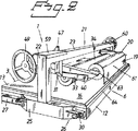
【図2】図2は、図1によるパターン付け装置の部分の斜視詳細図である。
【図3】図3は、図1によるパターン付け装置内に含まれる偏心手段の斜視詳細図である。
【図4】図4は、支持車輪がない、図1によるラミネート接合テーブルの概略側面図である。
【図5】図5は、上から見た図4によるラミネート接合テーブルの部品の概略上面図であり、テーブルリーフを取り外したフレーム構造を示す。
【図6】図6は、図1に示されるプレス装置内に含まれる横桁の側面図と上面図を示す。
【図7】図7は、図1に示されるプレス装置内に含まれる横桁の側面図と上面図を示す。
【図8】図8は、正面から見た、図1によるパターン付け装置の部分の概略正面図である。
【図9】図9は、ラミネート接合テーブルとの接触からプレスロールが上昇した第一の受動位置において、側面から見た、図1によるプレス装置の部品の概要詳細図である。
【図10】図10は、直線状の圧力がラミネート接合テーブル上と、その上に配置されたラミネート体の上で得られるように、プレスロールが下降した第二の能動位置において、側面から見た、図9によるプレス装置の部分の詳細図である。
【図11】図11は、偏心手段、取付部材及びプレスロール用の懸架装置の各部を含む、側面から見た、図8によるパターン付け装置の部分の概要詳細図である。
【図12】図12は、図1によるパターン付け装置内で使用する箔の概略斜視図であり、上記箔はパターン層、接着層及びキャリア層の三層を含み、上記箔は装飾と情報の両方の形式のパターン層内のパターンカットも有する。
【図13】図13は、第一のラミネート体を形成するために転写フィルムが付けられた、図12による箔の概略斜視図である。
【図14】図14は、第二のラミネート体を形成するために上記パターンと上記転写フィルムが支持手段の上に付けられた後での図13による第一のラミネート体の概略斜視図である。
【図15】図15は、転写フィルムが上記支持手段から取り外された後での図14による第二のラミネート体の概略斜視図である。 [0001]
【Technical field】
The present invention relates to a method for applying a predetermined pattern on the support means of the sign, said pattern being for forming decoration and / or information on the sign, the pattern layer and the carrier layer comprising Using the foil comprising the adhesive layer to bond, the portion included in the pattern is cut out in the pattern layer of the foil by means of a cutting device controlled by a pre-programmed electronic control unit according to a predetermined pattern, Thereafter, the present invention relates to a method in which a foil is disposed on a laminate bonding table having a flat arrangement surface in a patterning apparatus with a pattern layer facing upward.
[0002]
[Background]
The present invention is also a device for applying a predetermined pattern on the support means of the sign, the pattern being for forming decoration and / or information on the sign, the pattern layer and the carrier Utilizing a foil comprising layers together with an adhesive layer to join them, the part contained in the pattern is a pattern layer of foil by means of a cutting device controlled by an electronic control unit preprogrammed according to a predetermined pattern The apparatus relates to an apparatus comprising a laminate bonding table having a flat arrangement surface in a patterning device, wherein the foil is arranged with the pattern layer facing upwards.
[0003]
A conventional stretch fabric sign comprises a stand having a pair of parallel support elements fixed in a stand, a support means in the form of a flexible stretch fabric extending in a plane between the support elements, and a stretch fabric. And some form of attachment means for securing the to the support element. The two parallel ends of the fabric are folded around the strip so that the ends of the fabric can be detachably connected to the support element via the attachment means.
[0004]
Stretch fabric intended to support and expose information, especially advertisements, is attached to the marking surface of the stretch fabric and is a self-adhesive length of one or more decorative foil pattern layers, also known as decorative films By means of parts, it is suitably manufactured from some weather-resistant and durable material such as plastic sheets. The length of the decorative film is a desired pattern in the form of information, for example text or decoration, for example graphic, within the upper layer of the decorative foil comprising the decorative film with a thin adhesive layer facing the second layer. Produced by cutting, the backing typically includes a backing comprising waxed paper, and the underlying waxed paper is not perforated. When the desired pattern is first input to or created in the electronic control unit, the cutting is performed by a foil cutter, and usually a computer is connected to the foil cutter. The decorative foil thus cut is then placed on the table together with the stretch fabric. A transfer film with a self-adhesive non-permanent layer of adhesive on one surface of the transfer film is adhered over the entire surface of the pattern layer to form a laminate composed of foil and transfer film. The transfer film is generally wound with an adhesive layer facing toward the center of the roll, and no adhesive is always attached to the outside of the roll. The foil wax paper is then removed and the pattern layer is placed on the surface of the support means by removing all the wax paper at once, or in the case of larger pattern areas, so that the applied pattern covers only a small surface. The permanent adhesive surface of the pattern layer is exposed by the gradually exposing permanent adhesive surface as it is applied. During the removal of the wax paper, the cut-out portion of the pattern layer that forms a desired pattern is manually pushed out of the foil using a handheld tool such as a spatula and adhered to the surface of the transfer film. The portion of the pattern layer that does not form the desired pattern remains on the waxed paper and is discarded with the paper. When the wax paper is completely or partially removed in the manner described above, the short length of the pattern layer adhered to the transfer film is applied on the surface of the support means, i.e. the stretch fabric, and the patterning aids the spatula. While a new strip of adhesive surface is applied and at the same time the spatula smoothes the whole. Once the overall pattern layer is applied, the transfer film is finally removed from the current decorated stretch fabric.
[0005]
If the finished sign consists of multiple regions of different colors, each color must be cut out with a separate foil, and then each foil must be applied individually and individually on the stretch fabric. I must. Fixing and smoothing all the components in the manufacturing sign first was a very complex and cumbersome process. Furthermore, since it is difficult to reproduce the nature of the work, the pattern layer may be inadvertently and inaccurately attached. A spatula can also scratch or even tear the pattern layer or stretch fabric.
[0006]
To facilitate application, a lubricant such as water is generally used on the support means, and during the spatula operation there is less friction between the spatula and the transfer film. A serious problem that may occur is the formation of bubbles or blisters between the pattern layer and the stretch fabric, caused by water or air trapped between them. Holes must be formed in the pattern layer to remove these blisters and allow the contained liquid or air to be pushed out manually. Even if the pattern is applied with the utmost care, it may leave some blisters containing moisture. When the sign is subsequently suspended and heated by the sun, the moisture contained therein is converted to water vapor, and the bubbles gradually move the adhesive to the stretch fabric by bubbles, creating an unsightly, rough surface, To shorten the service life of Furthermore, the current patterning method requires two people, one with the spatula, while the other holds the foil in place. For a 16
[0007]
In another known method of applying a pattern layer on a stretch fabric, a patterned reel-up is provided when one layer is on top of the other and the layer passes through the nip between two rubber-covered press rolls. Is used, thereby providing adhesion between the required layers. However, placing the pattern layer in the press nip so that it is always accurately positioned relative to the bottom of the stretch fabric during the bonding process is extremely complicated because the adhesive layer is exposed. Even minor errors can cause significant lateral displacement after only a few meters of markings have passed through the press nip. This is especially true when two or more panels of pattern layers are applied next to or on top of each other. Thus, at present, there is no practical way to fabricate a stretchable fabric sign with a detailed and multi-colored pattern so that it is fast, reliable and cost effective.
[0008]
The patterned reel-up described above cannot be used when working with a large sign backing because the pattern layer cannot be patterned with a backing larger than the width of the press roll in the reel-up. Therefore, the width of the sign is limited to only about 1200 mm, which is a commonly used roll width. However, currently available foil cutters can manage foil widths up to 1372 mm, and for marketing reasons, it is desirable to produce larger stretch fabric signs by combining several panels of pattern layers So now the reel-up method is outdated.
[0009]
The main object of the present invention is to provide an improved method and apparatus for applying a pattern layer on a support means so as to completely or at least almost completely eliminate the above-mentioned problems.
[0010]
A second object of the present invention is to apply a pattern layer on a stretch fabric that is far wider than currently available pattern rolls, and simultaneously, parallelize multiple parallel pattern layers of the current maximum width panel with one panel. It is to provide a method and apparatus that allow patterning onto the same size support means.
[0011]
A third object of the present invention is to provide a method and apparatus that makes patterning simpler, faster, and requires less work in terms of time and personnel.
[0012]
Another object of the present invention is that manual assembling using a hand tool such as a spatula, lubricant, and the damage and inconvenience frequently caused by the hand tool and lubricant are greatly reduced or completely reduced. It is an object of the present invention to provide a method and apparatus that can be eliminated.
[0013]
DISCLOSURE OF THE INVENTION
The method according to the invention is characterized in that at least one of the traverses across the placement surface in the patterning device is passed over the foil placed on the laminate bonding table in a controlled manner and is pivotally supported at the end. A first laminate comprising a transfer film and a foil, a self-adhesive transfer film supplied from above and around the press roll and supported by a press device arranged in the cross beam is applied to the foil under pressure. The carrier part and the spilled material of the pattern layer are removed together or separately, and the pattern part remaining on the transfer film and adhering to the self-adhesive surface is the pattern part adhesive layer exposed at present. A cross roll is brought into contact with the support means at a certain arrangement surface, and is again passed under pressure through the second laminate to be formed. The pattern portion is permanently transferred to the support means, and during the patterning, the press roll pushes out air contained in the second laminate, and the transfer film is the support means. It is removed from.
[0014]
The device according to the present invention comprises a cross beam having a linearly operable device having control and pivoting means across the placement surface, said device moving along a fixed control, and the support part of the laminate joining table. Running parallel to each other along each long side, the press device is between an at least one press roll pivotally supported at the end and an upper inoperative position and a lower operating position in contact with the table surface. And a control means for moving the press roll to control the pressure of the press roll against the surface of the table.
[0015]
Compared to previously known methods, the present invention achieves up to 75% time savings. Using the present invention, a plurality of parallel patterns can also be easily and efficiently applied on the support means for the stretch fabric sign, which is much larger than the currently available press roll width, in this case In addition, the adjacent panels can be easily and accurately placed together before the foil is arranged for each panel on the patterning table, and then the pattern layer from the foil is fixed to the stretch fabric by the transfer film and the press roll. This is because it can be attached.
[0016]
A further advantage provided by the present invention is that during patterning, a lubricant such as water is not required between the pattern layer and the spatula, and the material used can be stretched or contracted with the spatula. It is not damaged by the water remaining between the fabrics. Since one end of the transfer film having the pattern prepared for cutting can be fixed to the supporting means by a press roll, the operation can be performed more rapidly. Thereafter, the carrier layer is removed, the adhesive layer is exposed, and patterning on the stretch fabric can be performed, while a cross beam with a press roll is passed over the table, thereby causing the pattern layer to adhere completely. produce.
[0017]
BEST MODE FOR CARRYING OUT THE INVENTION
The present invention will be described below with reference to the accompanying drawings.
[0018]
1 to 3 are schematic perspective views of each part of the
[0019]
The
[0020]
In the illustrated embodiment, the
[0021]
Referring to FIG. 12, the
[0022]
Referring to FIGS. 13 and 14, the
[0023]
The
[0024]
In the illustrated embodiment, each of the control and pivot means 26 includes two pairs of
[0025]
As can be seen in FIG. 2, the two
[0026]
In the embodiment shown, the spring and adjusting means 41 have a central threaded strut 45 extending between the elements, for this purpose, through holes provided in the horizontal flanges of the
[0027]
In order to actuate the
[0028]
With reference to FIGS. 9 to 11, the actuation and setting of the
[0029]
In order to prevent the risk of clamping when actuating the
[0030]
Further, FIG. 2 shows a
[0031]
The patterning of the
[0032]
After being cut out, the sheet of
[0033]
Thereafter, one of the
[0034]
When the
[0035]
In an alternative embodiment of the method desirable when using a length of
[0036]
Before or after patterning of the transfer film on the
[0037]
In this patterning method, the
[0038]
Here, since the linear pressure in the lower part is obtained in the direction of the
[0039]
In the illustrated embodiment, for example, the lowermost leaf of the table 3 that forms the
[0040]
In order to be able to select the optimum sled in a particular case, the leaves must be arranged relatively loosely with respect to the
[0041]
Other materials and materials of various thicknesses can be laminated and bonded to each other by the
[0042]
The
[0043]
In other embodiments of the present invention not shown, one or more sleeves may surround the
[0044]
Ultimately, since the required adhesiveness varies depending on the size of the
[0045]
[Brief description of the drawings]
[Figure 1]FIG. 1 is a schematic perspective view of a portion of a patterning device for use in the method according to the present invention as seen from the long side of the patterning device, including a pressing device and a laminate bonding table.
[Figure 2]FIG. 2 is a detailed perspective view of a part of the patterning device according to FIG.
[Fig. 3]3 is a detailed perspective view of the eccentric means included in the patterning device according to FIG.
[Fig. 4]4 is a schematic side view of the laminate joining table according to FIG. 1 without supporting wheels.
[Figure 5]FIG. 5 is a schematic top view of components of the laminate joint table according to FIG. 4 as viewed from above, showing the frame structure with the table leaf removed.
[Fig. 6]FIG. 6 shows a side view and a top view of the cross beam included in the pressing apparatus shown in FIG.
[Fig. 7]FIG. 7 shows a side view and a top view of the cross beam included in the pressing apparatus shown in FIG.
[Fig. 8]FIG. 8 is a schematic front view of the part of the patterning device according to FIG. 1 as seen from the front.
FIG. 9FIG. 9 is a schematic detailed view of the parts of the pressing device according to FIG. 1 as viewed from the side, in a first passive position where the press roll has risen from contact with the laminate joining table.
FIG. 10FIG. 10 is a side view in a second active position where the press roll is lowered so that a linear pressure is obtained on the laminate bonding table and on the laminate placed thereon. It is detail drawing of the part of the press apparatus by.
FIG. 11FIG. 11 is a schematic detailed view of the portion of the patterning device according to FIG. 8 as viewed from the side, including the eccentric means, the mounting member and the parts of the press roll suspension.
FIG.FIG. 12 is a schematic perspective view of a foil used in the patterning device according to FIG. 1, the foil comprising three layers: a pattern layer, an adhesive layer and a carrier layer, the foil being in both decorative and informational forms. It also has a pattern cut in the pattern layer.
FIG. 13FIG. 13 is a schematic perspective view of the foil according to FIG. 12 with a transfer film applied to form a first laminate.
FIG. 14FIG. 14 is a schematic perspective view of the first laminate according to FIG. 13 after the pattern and the transfer film have been applied onto the support means to form a second laminate.
FIG. 15FIG. 15 is a schematic perspective view of the second laminate according to FIG. 14 after the transfer film has been removed from the support means.
Claims (24)
(a)前記貼着装置(11)は、(A) The sticking device (11)
(a1)ラミネート接合テーブル(3)と、(A1) a laminate bonding table (3);
(a2)前記ラミネート接合テーブル(3)の上面部分を形成する平坦な載置部(13)であって、前記ラミネート接合テーブル(3)の上面を覆うマット(16)を備えた載置部(13)と、(A2) A flat mounting portion (13) for forming an upper surface portion of the laminate bonding table (3), the mounting portion including a mat (16) covering the upper surface of the laminate bonding table (3) ( 13)
(a3)前記マット(16)の表面に描かれた基準線及び測定線と、(A3) a reference line and a measurement line drawn on the surface of the mat (16);
(a4)前記マット(16)の前記表面によって形成されたテーブル表面(15)と、(A4) a table surface (15) formed by the surface of the mat (16);
(a5)前記載置部(13)の上方で前記載置部(13)の全幅に亘って延在するとともに、前記ラミネート接合テーブル(3)の長手方向に沿って移動可能な横桁(21)と、(A5) A cross beam (21 extending above the placement portion (13) over the entire width of the placement portion (13) and movable along the longitudinal direction of the laminate bonding table (3). )When,
(a6)前記横桁(21)に設けられたプレス装置(32)と、(A6) a pressing device (32) provided in the cross beam (21);
(a7)前記プレス装置(32)に回転可能に枢支されたプレスロール(34)と、(A7) a press roll (34) rotatably supported by the press device (32);
(a8)前記プレスロール(34)の上方近傍で前記横桁(21)に設けられた貯蔵ロール(20、61)であって、透明な一時的接着層(76)を備えた透明な転写フィルム(19)を巻き回した貯蔵ロール(20、61)と(A8) A transparent transfer film, which is a storage roll (20, 61) provided on the cross beam (21) in the vicinity of the upper side of the press roll (34), and is provided with a transparent temporary adhesive layer (76). A storage roll (20, 61) wound with (19)
を備えたものであり、With
(b)前記模様(70)は、模様層(18)と接着層(74)と剥離層(73)を積層した箔(17)から、前記模様層(18)を切り出して形成したものであり、(B) The pattern (70) is formed by cutting out the pattern layer (18) from the foil (17) obtained by laminating the pattern layer (18), the adhesive layer (74), and the release layer (73). ,
以下の工程(c)ないし(k)からなる貼着方法。A sticking method comprising the following steps (c) to (k).
(c)前記模様(70)に合わせて予めプログラムされている電子制御ユニットによって制御される切断装置を用いて、前記箔(17)の前記模様層(18)から前記模様(70)を切り出す工程、(C) cutting out the pattern (70) from the pattern layer (18) of the foil (17) using a cutting device controlled by an electronic control unit pre-programmed to the pattern (70). ,
(d)前記模様(70)を切り出した前記箔(17)を、前記模様層(18)を上方にして前記テーブル表面(15)に載置する工程、(D) placing the foil (17) cut out of the pattern (70) on the table surface (15) with the pattern layer (18) facing upward;
(e)前記貯蔵ロール(20、61)から前記転写フイルム(19)を引き出しながら、前記一時的接着層(76)を前記模様層(18)に接触させ、前記転写フイルム(19)の上方から前記プレスロール(34)で加圧しながら前記横桁(21)を移動させて、前記転写フイルム(19)と前記箔(17)とを一体化した第一のラミネート体(75)を作成する工程、(E) While pulling out the transfer film (19) from the storage roll (20, 61), the temporary adhesive layer (76) is brought into contact with the pattern layer (18), and from above the transfer film (19). The process of creating the 1st laminated body (75) which integrated the said transfer film (19) and the said foil (17) by moving the said cross beam (21), pressing with the said press roll (34). ,
(f)前記第一のラミネート体(75)から、前記剥離層(73)と、前記模様層(18)の不要部分とを除去する工程、(F) removing the release layer (73) and unnecessary portions of the pattern layer (18) from the first laminate (75);
(g)前記織物(2)を前記テーブル表面(15)に載置する工程、(G) placing the fabric (2) on the table surface (15);
(h)前記第一のラミネート体(75)の前縁部分を、前記一時的接着層(76)によって前記テーブル表面(15)に貼着するとともに、前記第一のラミネート体(75)と前記織物(2)と前記プレスロール(34)とを整列させる工程、(H) The front edge portion of the first laminate (75) is attached to the table surface (15) by the temporary adhesive layer (76), and the first laminate (75) and the Aligning the fabric (2) and the press roll (34);
(i)前記模様(70)となる前記模様層(18)と、前記織物(2)とを正確な位置に調整しながら、前記接着層(74)及び前記一時的接着層(76)を前記織物(2)に接触させて、第二のラミネート体(77)を作成する工程、(I) While adjusting the pattern layer (18) to be the pattern (70) and the fabric (2) to an accurate position, the adhesive layer (74) and the temporary adhesive layer (76) are Contacting the fabric (2) to produce a second laminate (77);
(j)前記プレスロール(34)で前記第二のラミネート体(77)を加圧しながら前記横桁(21)を移動させて、前記第二のラミネート体(77)に閉じ込められていた空気を押し出すとともに、前記模様層(18)を前記織物(2)に恒久的に接着する工程、(J) While pressing the second laminate (77) with the press roll (34), the cross beam (21) is moved so that the air trapped in the second laminate (77) is removed. Extruding and permanently bonding the patterned layer (18) to the fabric (2);
(k)前記第二のラミネート体(77)から、前記転写フィルム(19)を除去する工程。(K) A step of removing the transfer film (19) from the second laminate (77).
(l)前記織物(2)を前記テーブル表面(15)に載置する工程、(L) placing the fabric (2) on the table surface (15);
(m)前記第一のラミネート体(75)の前記剥離層(73)が、前記織物(2)側になるようにして、前記第一のラミネート体(75)を前記織物(2)に重ねる工程、(M) The first laminate (75) is overlaid on the fabric (2) so that the release layer (73) of the first laminate (75) is on the fabric (2) side. Process,
(n)前記プレスロール(34)を降下させて、前記第一のラミネート体(75)の長手方向端部とは異なる位置において前記第一のラミネート体(75)に接触させ、前記第一のラミネート体(75)と前記織物(2)とを、前記プレスロール(34)と前記テーブル表面(15)との間に挟み込む工程、(N) The press roll (34) is lowered and brought into contact with the first laminate (75) at a position different from the longitudinal end of the first laminate (75), Sandwiching the laminate (75) and the fabric (2) between the press roll (34) and the table surface (15);
(o)前記第一のラミネート体(75)の一方の端部から、前記プレスロール(34)との接触位置までの部分について、前記剥離層(73)と前記模様層(18)の不要部分とを除去する工程、(O) Unnecessary portions of the release layer (73) and the patterned layer (18) with respect to a portion from one end of the first laminate (75) to the contact position with the press roll (34). And a step of removing
(p)前記模様(70)となる前記模様層(18)と、前記織物(2)とを正確な位置に調整しながら、前記接着層(74)及び前記一時的接着層(76)を前記織物(2)に接触させて、第二のラミネート体(77)の第一の部分を作成する工程、(P) While adjusting the pattern layer (18) to be the pattern (70) and the fabric (2) to an accurate position, the adhesive layer (74) and the temporary adhesive layer (76) are Making the first part of the second laminate (77) in contact with the fabric (2);
(q)前記プレスロール(34)で前記第二のラミネート体(77)の第一の部分を加圧しながら前記横桁(21)を移動させて、前記第二のラミネート体(77)の第一の部分に閉じ込められていた空気を押し出すとともに、前記模様層(18)を前記織物(2)に恒久的に接着する工程、(Q) The cross beam (21) is moved while pressing the first portion of the second laminate (77) with the press roll (34), and the second laminate (77) Extruding air trapped in one part and permanently adhering the patterned layer (18) to the fabric (2);
(r)前記第一のラミネート体(75)に残っている前記剥離層(73)と前記模様層(18)の不要部分とを除去する工程、(R) removing the release layer (73) remaining in the first laminate (75) and unnecessary portions of the pattern layer (18);
(s)前記模様(70)となる前記模様層(18)と、前記織物(2)とを正確な位置に調整しながら、前記接着層(74)及び前記一時的接着層(76)を前記織物(2)に接触させて、第二のラミネート体(77)の第二の部分を作成する工程、(S) While adjusting the pattern layer (18) to be the pattern (70) and the fabric (2) to an accurate position, the adhesive layer (74) and the temporary adhesive layer (76) are Contacting the fabric (2) to create a second portion of the second laminate (77);
(t)前記プレスロール(34)で前記第二のラミネート体(77)の第二の部分を加圧しながら前記横桁(21)を移動させて、前記第二のラミネート体(77)の第二の部分に閉じ込められていた空気を押し出すとともに、前記模様層(18)を前記織物(2)に恒久的に接着する工程。(T) The cross beam (21) is moved while pressing the second portion of the second laminate (77) with the press roll (34), and the second laminate (77) Extruding air trapped in the second part and permanently adhering the patterned layer (18) to the fabric (2).
(a)ラミネート接合テーブル(3)と、(A) a laminate bonding table (3);
(b)前記ラミネート接合テーブル(3)の上面部分を形成する平坦な載置部(13)であって、前記ラミネート接合テーブル(3)の上面を覆うマット(16)を備えた載置部(13)と、(B) A flat mounting portion (13) for forming an upper surface portion of the laminate bonding table (3), the mounting portion (13) including a mat (16) covering the upper surface of the laminate bonding table (3). 13)
(c)前記マット(16)の表面に描かれた基準線及び測定線と、(C) a reference line and a measurement line drawn on the surface of the mat (16);
(d)前記マット(16)の前記表面によって形成されたテーブル表面(15)と、(D) a table surface (15) formed by the surface of the mat (16);
(e)2つの柱(22)と、前記柱(22)の両上端間に延び、前記載置部(13)の上方で前記載置部(13)の全幅に亘って延在するブーム(23)とを備え、前記ラミネート接合テーブル(3)の長手方向に沿って移動可能な横桁(21)と、(E) A boom extending between the two pillars (22) and the upper ends of the pillars (22) and extending over the entire width of the placement part (13) above the placement part (13). 23), and a cross beam (21) movable along the longitudinal direction of the laminate bonding table (3),
(f)前記ラミネート接合テーブル(3)の各長側面(5)に設けられた、前記2つの柱(22)を支持及び案内するための固定レール(27)と、(F) a fixed rail (27) for supporting and guiding the two pillars (22) provided on each long side surface (5) of the laminate joining table (3);
(g)前記横桁(21)に設けられたプレス装置(32)と、(G) a pressing device (32) provided in the cross beam (21);
(h)前記プレス装置(32)に回転可能に枢支されたプレスロール(34)と、(H) a press roll (34) rotatably supported by the press device (32);
(i)前記プレスロール(34)の上方近傍で前記横桁(21)に設けられた貯蔵ロール(20、61)であって、透明な一時的接着層(76)を備えた透明な転写フィルム(19)を巻回した貯蔵ロール(20、61)と(I) A transparent transfer film provided with a transparent temporary adhesive layer (76), which is a storage roll (20, 61) provided on the cross beam (21) near the upper side of the press roll (34). A storage roll (20, 61) wound with (19)
を備えた貼着装置。A sticking device comprising:
Applications Claiming Priority (3)
| Application Number | Priority Date | Filing Date | Title |
|---|---|---|---|
| SE9702032A SE509455C2 (en) | 1997-05-30 | 1997-05-30 | Method and apparatus for applying a pattern to a carrier for a sign |
| SE9702032-5 | 1997-05-30 | ||
| PCT/SE1998/000924 WO1998053987A1 (en) | 1997-05-30 | 1998-05-18 | Method and device for applying a pattern onto a support means |
Publications (3)
| Publication Number | Publication Date |
|---|---|
| JP2002502342A JP2002502342A (en) | 2002-01-22 |
| JP2002502342A5 JP2002502342A5 (en) | 2010-12-24 |
| JP4750913B2 true JP4750913B2 (en) | 2011-08-17 |
Family
ID=20407154
Family Applications (1)
| Application Number | Title | Priority Date | Filing Date |
|---|---|---|---|
| JP50056399A Expired - Lifetime JP4750913B2 (en) | 1997-05-30 | 1998-05-18 | Method and apparatus for applying a pattern on a support means |
Country Status (16)
| Country | Link |
|---|---|
| EP (1) | EP0986459B1 (en) |
| JP (1) | JP4750913B2 (en) |
| CN (1) | CN1093033C (en) |
| AT (1) | ATE277753T1 (en) |
| AU (1) | AU730769B2 (en) |
| BR (1) | BR9809530A (en) |
| CA (1) | CA2289469C (en) |
| DE (1) | DE69826655T2 (en) |
| ES (1) | ES2230695T3 (en) |
| IL (1) | IL132849A (en) |
| NO (1) | NO315014B1 (en) |
| PL (1) | PL191096B1 (en) |
| RU (1) | RU2220050C2 (en) |
| SE (1) | SE509455C2 (en) |
| TR (1) | TR199902925T2 (en) |
| WO (1) | WO1998053987A1 (en) |
Families Citing this family (15)
| Publication number | Priority date | Publication date | Assignee | Title |
|---|---|---|---|---|
| US7807001B2 (en) * | 2007-06-28 | 2010-10-05 | Eastman Kodak Company | Lamination device method for flexographic plate manufacturing |
| EP2409826A1 (en) | 2010-07-19 | 2012-01-25 | Rapid Applicator B.V. | Device and method for applying a pattern on a support means |
| EP2422978A1 (en) | 2010-08-26 | 2012-02-29 | Modulmounter ApS | Laminating device |
| DE202010011880U1 (en) | 2010-08-26 | 2011-02-10 | Walter, William | laminating |
| DE202010011881U1 (en) | 2010-08-26 | 2011-03-24 | Walter, William | Flatbed laminator without overlapping crossbar |
| KR200467074Y1 (en) * | 2010-10-12 | 2013-05-23 | (주)엘지하우시스 | Wrapping apparatus for profile |
| NO20110696A1 (en) * | 2011-05-10 | 2012-11-12 | Jarle Hansen | Lamination Table |
| CN104827743B (en) * | 2015-04-15 | 2017-02-22 | 江苏比微曼智能科技有限公司 | Apparatus for attaching film |
| ITUB20151948A1 (en) * | 2015-07-08 | 2017-01-08 | New Tech Srl | Method and plant for making tiles for floating floors |
| CN105712123B (en) * | 2016-04-28 | 2017-10-27 | 常州市宏发纵横新材料科技股份有限公司 | Laying apparatus and laying method before a kind of enhancing fabric sewing |
| WO2020078646A1 (en) | 2018-10-17 | 2020-04-23 | Cwt Worktools Ab | A flat bed applicator arrangement and a method for use of a flat bed applicator arrangement |
| SE542854C2 (en) * | 2018-10-17 | 2020-07-21 | Cwt Worktools Ab | A flat bed applicator arrangement and a method for use of a flat bed applicator arrangement |
| WO2020078645A1 (en) | 2018-10-17 | 2020-04-23 | Cwt Worktools Ab | A flat bed applicator arrangement and a method for use of a flat bed applicator arrangement |
| CN110136610B (en) * | 2019-05-25 | 2020-12-25 | 北京东方星月传媒广告有限公司 | Advertising box |
| SE545971C2 (en) * | 2022-05-26 | 2024-04-02 | Moditech Scandinavia Ab | Flatbed applicator and related method |
Family Cites Families (5)
| Publication number | Priority date | Publication date | Assignee | Title |
|---|---|---|---|---|
| GB2099362B (en) * | 1978-05-19 | 1983-04-27 | Minnesota Mining & Mfg | Sheet-laminating apparatus |
| JP2637261B2 (en) * | 1990-05-22 | 1997-08-06 | ソマール株式会社 | Laminator |
| US5124187A (en) * | 1990-10-10 | 1992-06-23 | Aeschbacher Lori L | Adhesive sheet materials for signmaking machines |
| AU4085793A (en) * | 1992-05-27 | 1993-12-30 | Plastisign Limited | Method of cold laminating rigid plastics and stationery and apparatus therefor |
| US5686170A (en) * | 1995-12-21 | 1997-11-11 | Minnesota Mining And Manufacturing Company | Labor-saving process and article for making dimensional sign graphics |
-
1997
- 1997-05-30 SE SE9702032A patent/SE509455C2/en not_active IP Right Cessation
-
1998
- 1998-05-18 JP JP50056399A patent/JP4750913B2/en not_active Expired - Lifetime
- 1998-05-18 AU AU77925/98A patent/AU730769B2/en not_active Expired
- 1998-05-18 CN CN98805672A patent/CN1093033C/en not_active Expired - Lifetime
- 1998-05-18 EP EP98925995A patent/EP0986459B1/en not_active Expired - Lifetime
- 1998-05-18 AT AT98925995T patent/ATE277753T1/en not_active IP Right Cessation
- 1998-05-18 BR BR9809530-7A patent/BR9809530A/en not_active IP Right Cessation
- 1998-05-18 IL IL13284998A patent/IL132849A/en not_active IP Right Cessation
- 1998-05-18 PL PL336939A patent/PL191096B1/en unknown
- 1998-05-18 RU RU99128071/12A patent/RU2220050C2/en active
- 1998-05-18 CA CA002289469A patent/CA2289469C/en not_active Expired - Lifetime
- 1998-05-18 DE DE69826655T patent/DE69826655T2/en not_active Expired - Lifetime
- 1998-05-18 WO PCT/SE1998/000924 patent/WO1998053987A1/en active IP Right Grant
- 1998-05-18 TR TR1999/02925T patent/TR199902925T2/en unknown
- 1998-05-18 ES ES98925995T patent/ES2230695T3/en not_active Expired - Lifetime
-
1999
- 1999-11-15 NO NO19995596A patent/NO315014B1/en not_active IP Right Cessation
Also Published As
| Publication number | Publication date |
|---|---|
| CA2289469A1 (en) | 1998-12-03 |
| NO315014B1 (en) | 2003-06-23 |
| DE69826655T2 (en) | 2006-02-23 |
| TR199902925T2 (en) | 2001-03-21 |
| NO995596L (en) | 1999-11-15 |
| AU7792598A (en) | 1998-12-30 |
| ES2230695T3 (en) | 2005-05-01 |
| PL191096B1 (en) | 2006-03-31 |
| IL132849A0 (en) | 2001-03-19 |
| SE509455C2 (en) | 1999-01-25 |
| EP0986459B1 (en) | 2004-09-29 |
| WO1998053987A1 (en) | 1998-12-03 |
| CN1093033C (en) | 2002-10-23 |
| AU730769B2 (en) | 2001-03-15 |
| PL336939A1 (en) | 2000-07-17 |
| CA2289469C (en) | 2004-11-09 |
| SE9702032D0 (en) | 1997-05-30 |
| NO995596D0 (en) | 1999-11-15 |
| RU2220050C2 (en) | 2003-12-27 |
| EP0986459A1 (en) | 2000-03-22 |
| IL132849A (en) | 2002-12-01 |
| DE69826655D1 (en) | 2004-11-04 |
| JP2002502342A (en) | 2002-01-22 |
| ATE277753T1 (en) | 2004-10-15 |
| SE9702032L (en) | 1998-12-01 |
| CN1259080A (en) | 2000-07-05 |
| BR9809530A (en) | 2000-06-20 |
Similar Documents
| Publication | Publication Date | Title |
|---|---|---|
| JP4750913B2 (en) | Method and apparatus for applying a pattern on a support means | |
| US6406582B1 (en) | Method for applying a pattern onto a support | |
| JP2002502342A5 (en) | ||
| EP0650154B1 (en) | Labels and manufacture thereof | |
| DE4202553C2 (en) | LAMINATOR | |
| RU99128071A (en) | METHOD AND DEVICE FOR DRAWING A FIGURE ON A SUBSTRATE | |
| JP3327727B2 (en) | Sheet cutting equipment | |
| DE1911615A1 (en) | Device for applying a double-sided adhesive film | |
| US5352314A (en) | Graphics transfer applicator | |
| US6284076B1 (en) | Signage masking tool and method | |
| DE4033834A1 (en) | METHOD FOR PRODUCING AN INTERRUPTED STICKER SHEET | |
| US20040076492A1 (en) | Method and device for making the covers of a book or equivalent | |
| US6709541B2 (en) | Apparatus and method for the transfer of sign graphics | |
| MXPA99010764A (en) | Method and device for applying a pattern onto a support means | |
| JP6906744B2 (en) | Prepreg sheet automatic laminating device | |
| KR200408811Y1 (en) | Book label manufacture machine | |
| EP2409826A1 (en) | Device and method for applying a pattern on a support means | |
| JP4428751B2 (en) | Equipment for manufacturing long sheets with adhesive tape | |
| KR100695451B1 (en) | Book label structure | |
| KR200411637Y1 (en) | Book label structure | |
| CN210911659U (en) | Automatic film laminating machine | |
| JP4606648B2 (en) | Film end processing mechanism and film supply apparatus provided with this film end processing mechanism | |
| DE2413051A1 (en) | Self-adhesive film - with protective layer of water-soluble adhesive permitting correct alignment without creasing or air inclusions | |
| GB2099362A (en) | Sheet-laminating apparatus | |
| CN201253978Y (en) | Antisticking fence plate of continuous cold mounting laminating machine |
Legal Events
| Date | Code | Title | Description |
|---|---|---|---|
| A621 | Written request for application examination |
Free format text: JAPANESE INTERMEDIATE CODE: A621 Effective date: 20041217 |
|
| A131 | Notification of reasons for refusal |
Free format text: JAPANESE INTERMEDIATE CODE: A131 Effective date: 20070522 |
|
| A601 | Written request for extension of time |
Free format text: JAPANESE INTERMEDIATE CODE: A601 Effective date: 20070719 |
|
| A602 | Written permission of extension of time |
Free format text: JAPANESE INTERMEDIATE CODE: A602 Effective date: 20070827 |
|
| A601 | Written request for extension of time |
Free format text: JAPANESE INTERMEDIATE CODE: A601 Effective date: 20070921 |
|
| A602 | Written permission of extension of time |
Free format text: JAPANESE INTERMEDIATE CODE: A602 Effective date: 20071029 |
|
| A601 | Written request for extension of time |
Free format text: JAPANESE INTERMEDIATE CODE: A601 Effective date: 20071018 |
|
| A602 | Written permission of extension of time |
Free format text: JAPANESE INTERMEDIATE CODE: A602 Effective date: 20071126 |
|
| A521 | Request for written amendment filed |
Free format text: JAPANESE INTERMEDIATE CODE: A523 Effective date: 20071121 |
|
| A02 | Decision of refusal |
Free format text: JAPANESE INTERMEDIATE CODE: A02 Effective date: 20080722 |
|
| A521 | Request for written amendment filed |
Free format text: JAPANESE INTERMEDIATE CODE: A523 Effective date: 20081119 |
|
| A521 | Request for written amendment filed |
Free format text: JAPANESE INTERMEDIATE CODE: A523 Effective date: 20081212 |
|
| A911 | Transfer to examiner for re-examination before appeal (zenchi) |
Free format text: JAPANESE INTERMEDIATE CODE: A911 Effective date: 20090205 |
|
| A711 | Notification of change in applicant |
Free format text: JAPANESE INTERMEDIATE CODE: A711 Effective date: 20091208 |
|
| A912 | Re-examination (zenchi) completed and case transferred to appeal board |
Free format text: JAPANESE INTERMEDIATE CODE: A912 Effective date: 20091210 |
|
| A521 | Request for written amendment filed |
Free format text: JAPANESE INTERMEDIATE CODE: A821 Effective date: 20091208 |
|
| A601 | Written request for extension of time |
Free format text: JAPANESE INTERMEDIATE CODE: A601 Effective date: 20100709 |
|
| A602 | Written permission of extension of time |
Free format text: JAPANESE INTERMEDIATE CODE: A602 Effective date: 20100714 |
|
| A601 | Written request for extension of time |
Free format text: JAPANESE INTERMEDIATE CODE: A601 Effective date: 20100906 |
|
| A602 | Written permission of extension of time |
Free format text: JAPANESE INTERMEDIATE CODE: A602 Effective date: 20100909 |
|
| A601 | Written request for extension of time |
Free format text: JAPANESE INTERMEDIATE CODE: A601 Effective date: 20101006 |
|
| A602 | Written permission of extension of time |
Free format text: JAPANESE INTERMEDIATE CODE: A602 Effective date: 20101012 |
|
| A524 | Written submission of copy of amendment under article 19 pct |
Free format text: JAPANESE INTERMEDIATE CODE: A524 Effective date: 20101108 |
|
| A521 | Request for written amendment filed |
Free format text: JAPANESE INTERMEDIATE CODE: A523 Effective date: 20110405 |
|
| A01 | Written decision to grant a patent or to grant a registration (utility model) |
Free format text: JAPANESE INTERMEDIATE CODE: A01 |
|
| A61 | First payment of annual fees (during grant procedure) |
Free format text: JAPANESE INTERMEDIATE CODE: A61 Effective date: 20110520 |
|
| R150 | Certificate of patent or registration of utility model |
Free format text: JAPANESE INTERMEDIATE CODE: R150 |
|
| FPAY | Renewal fee payment (event date is renewal date of database) |
Free format text: PAYMENT UNTIL: 20140527 Year of fee payment: 3 |
|
| R250 | Receipt of annual fees |
Free format text: JAPANESE INTERMEDIATE CODE: R250 |
|
| R250 | Receipt of annual fees |
Free format text: JAPANESE INTERMEDIATE CODE: R250 |
|
| R250 | Receipt of annual fees |
Free format text: JAPANESE INTERMEDIATE CODE: R250 |
|
| R250 | Receipt of annual fees |
Free format text: JAPANESE INTERMEDIATE CODE: R250 |
|
| EXPY | Cancellation because of completion of term |