JP4750402B2 - Optical equipment - Google Patents
Optical equipment Download PDFInfo
- Publication number
- JP4750402B2 JP4750402B2 JP2004318120A JP2004318120A JP4750402B2 JP 4750402 B2 JP4750402 B2 JP 4750402B2 JP 2004318120 A JP2004318120 A JP 2004318120A JP 2004318120 A JP2004318120 A JP 2004318120A JP 4750402 B2 JP4750402 B2 JP 4750402B2
- Authority
- JP
- Japan
- Prior art keywords
- lens
- optical axis
- unit
- magnet
- shift
- Prior art date
- Legal status (The legal status is an assumption and is not a legal conclusion. Google has not performed a legal analysis and makes no representation as to the accuracy of the status listed.)
- Expired - Fee Related
Links
Images


Classifications
-
- G—PHYSICS
- G03—PHOTOGRAPHY; CINEMATOGRAPHY; ANALOGOUS TECHNIQUES USING WAVES OTHER THAN OPTICAL WAVES; ELECTROGRAPHY; HOLOGRAPHY
- G03B—APPARATUS OR ARRANGEMENTS FOR TAKING PHOTOGRAPHS OR FOR PROJECTING OR VIEWING THEM; APPARATUS OR ARRANGEMENTS EMPLOYING ANALOGOUS TECHNIQUES USING WAVES OTHER THAN OPTICAL WAVES; ACCESSORIES THEREFOR
- G03B17/00—Details of cameras or camera bodies; Accessories therefor
- G03B17/02—Bodies
-
- G—PHYSICS
- G02—OPTICS
- G02B—OPTICAL ELEMENTS, SYSTEMS OR APPARATUS
- G02B27/00—Optical systems or apparatus not provided for by any of the groups G02B1/00 - G02B26/00, G02B30/00
- G02B27/64—Imaging systems using optical elements for stabilisation of the lateral and angular position of the image
- G02B27/646—Imaging systems using optical elements for stabilisation of the lateral and angular position of the image compensating for small deviations, e.g. due to vibration or shake
-
- H—ELECTRICITY
- H04—ELECTRIC COMMUNICATION TECHNIQUE
- H04N—PICTORIAL COMMUNICATION, e.g. TELEVISION
- H04N23/00—Cameras or camera modules comprising electronic image sensors; Control thereof
- H04N23/60—Control of cameras or camera modules
- H04N23/68—Control of cameras or camera modules for stable pick-up of the scene, e.g. compensating for camera body vibrations
- H04N23/681—Motion detection
- H04N23/6812—Motion detection based on additional sensors, e.g. acceleration sensors
-
- H—ELECTRICITY
- H04—ELECTRIC COMMUNICATION TECHNIQUE
- H04N—PICTORIAL COMMUNICATION, e.g. TELEVISION
- H04N23/00—Cameras or camera modules comprising electronic image sensors; Control thereof
- H04N23/60—Control of cameras or camera modules
- H04N23/68—Control of cameras or camera modules for stable pick-up of the scene, e.g. compensating for camera body vibrations
- H04N23/682—Vibration or motion blur correction
- H04N23/685—Vibration or motion blur correction performed by mechanical compensation
- H04N23/687—Vibration or motion blur correction performed by mechanical compensation by shifting the lens or sensor position
Landscapes
- Engineering & Computer Science (AREA)
- Multimedia (AREA)
- Signal Processing (AREA)
- Physics & Mathematics (AREA)
- General Physics & Mathematics (AREA)
- Optics & Photonics (AREA)
- Adjustment Of Camera Lenses (AREA)
- Lens Barrels (AREA)
Description
本発明は、ビデオカメラやデジタルスチールカメラ等の撮像装置や交換タイプのレンズ装置などの光学機器に関するものである。 The present invention relates to an optical apparatus such as an imaging apparatus such as a video camera or a digital still camera, or an interchangeable lens apparatus.
撮像装置や交換レンズ装置には、光軸に略直交する方向にレンズを移動させることによって、撮影光学系の光軸を曲げ、手振れ等に起因する像振れを補正する振れ補正装置が搭載されていることが多い。このような振れ補正装置では、レンズ鏡筒内部のスペースを有効に使用するために、光軸と垂直な平面内において、振れ補正装置の一部が他のレンズ移動枠の一部と重なる、或いは他のレンズ移動枠の一部が振れ補正装置の一部と重なるという特許文献1のタイプが知られており、振れ補正装置中のマグネットやコイルなどの駆動発生部は、光軸と直交する方向において、被駆動ガラスと同一平面内に配置することが一般的である。
The imaging device and the interchangeable lens device are equipped with a shake correction device that corrects image shake caused by camera shake or the like by bending the optical axis of the photographing optical system by moving the lens in a direction substantially orthogonal to the optical axis. There are many. In such a shake correction apparatus, in order to effectively use the space inside the lens barrel, a part of the shake correction apparatus overlaps with a part of another lens moving frame in a plane perpendicular to the optical axis, or A type of
しかしながら、被駆動ガラスの内側に光量調節ユニットが挿入されている場合に、光量調節装置を避けてその外側にコイルやマグネットを配置すると、振れ補正装置の大径化を招いてしまう。 However, when the light amount adjustment unit is inserted inside the driven glass, if the coil or magnet is disposed outside the light amount adjustment device, the shake correction device will be increased in diameter.
本発明の目的は、上述の問題点を解消し、振れ補正手段を効率良く内部に配置した小型の光学機器を提供することにある。 An object of the present invention is to solve the above-mentioned problems and to provide a small optical apparatus in which shake correction means is efficiently arranged inside.
上記目的を達成するための本発明に係る光学機器の技術的特徴は、光軸方向において光量調節ユニットを挟んで物体側に配置された第1の補正レンズと像面側に配置された第2の補正レンズと、前記第1及び第2の補正レンズを一体的に連結する連結部を有し前記第1及び第2の補正レンズを保持する第1のレンズ移動枠と、像振れを補正するために光軸に垂直な平面内で前記第1のレンズ移動枠を移動させ、前記光軸方向において前記連結部よりも物体側に配置されたコイルとマグネットとを含む駆動手段と、前記第1の補正レンズよりも物体側に配置され前記光軸方向に移動して変倍を行う変倍レンズと、前記変倍レンズを保持する第2のレンズ移動枠と、を有し、前記光軸方向から見た場合に前記コイルと前記マグネットと前記連結部とが重なっており、前記コイルと前記マグネットとのうち一方が前記第1のレンズ移動枠に固定され、他方が前記第1のレンズ移動枠を前記光軸に垂直な平面内で移動可能に支持するベース部材に固定され、前記コイルと前記マグネットとのうち少なくとも何れかが前記第1の補正レンズよりも物体側に配置され、前記第2のレンズ移動枠が像面側に移動した際に、前記変倍レンズの一部が前記光軸に垂直な平面内において前記第1の補正レンズよりも物体側に配置された前記コイルと前記マグネットとのうち少なくとも何れかと重なるようにしたことにある。 In order to achieve the above object, the technical features of the optical apparatus according to the present invention include a first correction lens disposed on the object side with the light amount adjustment unit in the optical axis direction and a second lens disposed on the image plane side. A correction lens, a first lens moving frame that includes a connecting portion that integrally connects the first and second correction lenses, and that holds the first and second correction lenses, and corrects image blur. For this purpose, the first lens moving frame is moved in a plane perpendicular to the optical axis, and driving means including a coil and a magnet disposed on the object side of the connecting portion in the optical axis direction, and the first A zoom lens that is arranged closer to the object side than the correction lens and performs zooming by moving in the optical axis direction, and a second lens moving frame that holds the zoom lens, and the optical axis direction When viewed from the coil, the magnet and the connecting portion And one of the coil and the magnet is fixed to the first lens moving frame, and the other supports the first lens moving frame so as to be movable in a plane perpendicular to the optical axis. When fixed to a base member, at least one of the coil and the magnet is disposed closer to the object side than the first correction lens, and when the second lens moving frame moves to the image plane side, A part of the zoom lens overlaps at least one of the coil and the magnet arranged on the object side of the first correction lens in a plane perpendicular to the optical axis.
本発明に係る光学機器によれば、振れ補正手段を空間内の空スペースに効率良く配置し小型化が可能となる。 According to the optical apparatus according to the present invention, it is possible to reduce the size by efficiently arranging the shake correction means in an empty space in the space.
本発明を図示の実施例に基づいて詳細に説明する。
図1は実施例のカメラの斜視図である。カメラ本体1内には、ズーミングが可能なレンズ鏡筒2内の撮影光学系により形成された被写体像を記録するための銀塩フィルム又は撮像素子が収納されている。
The present invention will be described in detail based on the embodiments shown in the drawings.
FIG. 1 is a perspective view of the camera of the embodiment. In the
図2はレンズ鏡筒2の分解斜視図、図3はレンズ鏡筒2の断面図を示し、撮影光学系は物体側から順に、凸、凹、凸、凸の第1、第2、第3,第4レンズユニットL1、L2、L3、L4により構成されたレンズ光学系を有している。また、図4は第2レンズユニットL2の望遠側位置での拡大断面図であり、振れ補正装置としてのシフトユニット部3及びレンズ機構を示している。
2 is an exploded perspective view of the
第2レンズユニットL2(第2のレンズ移動枠)は光軸方向に移動することにより変倍作用を行い、複数枚のレンズを有する第3レンズユニットL3(第1のレンズ移動枠)は光軸Aに対して略直交する光軸直交面内、即ち光軸Aに対して略直交する光軸直交方向に移動することにより撮影光束を屈曲させて振れ補正作用を行うようになっている。この第3レンズユニットL3は、物体側に配置された第3aレンズサブユニットL3a(第1のレンズ保持部)と、像面側に配置された第3bレンズサブユニットL3b(第2のレンズ保持部)とに二体化されている。また、第4レンズユニットL4は光軸方向に移動することにより、焦点調節作用を行う。 The second lens unit L2 (second lens moving frame) performs a zooming action by moving in the optical axis direction, and the third lens unit L3 (first lens moving frame) having a plurality of lenses is an optical axis. By moving in the optical axis orthogonal plane substantially orthogonal to A, that is, in the optical axis orthogonal direction approximately orthogonal to the optical axis A, the photographic light beam is bent to perform a shake correction function. The third lens unit L3 includes a 3a lens subunit L3a (first lens holding unit) disposed on the object side and a 3b lens subunit L3b (second lens holding unit) disposed on the image plane side. ) And two . Further, the fourth lens unit L4 performs a focus adjusting action by moving in the optical axis direction.
また、第1レンズユニットL1は前玉鏡筒4により保持され、前玉鏡筒4の後端に結合された所定位置に固定され、前玉鏡筒4の後部に接続された固定鏡筒5の後端は、シフトユニット部3のベース部材であるシフトベース3aに結合され、シフトベース3aに後部鏡筒6が結合されている。
The first lens unit L <b> 1 is held by the
第2レンズユニットL2はバリエータ移動枠7に保持され、第3aレンズサブユニットL3aと第3bレンズサブユニットL3bはシフトユニット部3に一体的に保持され、これらを光軸直交方向に移動させるようになっている。
The second lens unit L2 is held by the
後部鏡筒6には、CCDセンサやCMOSセンサ等の撮像素子8が中間部材8aを介して取り付けられており、この中間部材8aは撮像素子8を接着等により固定した後に、後部鏡筒6に対してビス止めされている。
An
固定鏡筒5と後部鏡筒6との間に第1ガイドバー9aが保持され、固定鏡筒5に第2ガイドバー9bが圧入されている。また、シフトベース3aと後部鏡筒6との間に第3、第4ガイドバー9c、9dが保持されている。そして、第1、第2ガイドバー9a、9bによりバリエータ移動枠7が光軸方向に移動可能に支持され、第3、第4ガイドバー9c、9dによりレンズユニットL4を保持するフォーカス移動枠10が光軸方向に移動可能に支持されている。
A
シフトユニット部3のシフトベース3aは、固定鏡筒5に対する位置決め後に、後部鏡筒6と固定鏡筒5との間に挟み込まれ、これらに結合されている。シフトユニット部3内には、撮影光学系に入射した光量を変化させるための光量調節ユニット11がシフトベース3aにビス止めにより固定されて組み込まれ、2枚の絞り羽根11a、11bを光軸直交方向に移動させて開口径を変化させる。また光量調節ユニット11には、2濃度のNDフィルタ11cが絞り羽根11a、11bとは独立して、光路に対して進退できるように配置されている。
The
後部鏡筒6は固定鏡筒5に対して位置決めされ、かつ前述したようにシフトベース3aを挟み込んだ上で、ビスにより後方から共締め固定される。この際に、固定鏡筒5の後端上部に形成された係合穴部5aと、後部鏡筒6の前端上部に形成された係合突起部6aとが係合されている。
The
第4レンズユニットL4を固定したフォーカス移動枠10は、ボイスコイルモータから成るフォーカスモータにより光軸方向に駆動され、このフォーカスモータはコイル10a、ドライブマグネット10b、ヨーク部材10cにより構成されている。ここで、コイル10aに電流を流すと、マグネット10bとコイル10aとの間に発生する磁力線相互の反発によるローレンツ力が発生し、フォーカス移動枠10が光軸方向に駆動される。
The
またフォーカス移動枠10には、光軸方向に多極着磁された図示しないセンサマグネットが保持されており、後部鏡筒6におけるセンサマグネットに対向した位置には、センサマグネットの移動に伴う磁力線の変化を読み取るMRセンサ10dがビス止め固定されている。MRセンサ10dからの信号を用いることで、フォーカス移動枠10つまりは第4レンズユニットL4の所定の基準位置からの移動量を検出することができる。
The
第2レンズユニットL2を固定したバリエータ移動枠7は、ズームモータとして作用するステッピングモータ7aにより光軸方向に駆動される。このステッピングモータ7aは支持部材を介して固定鏡筒5にビス止め固定され、その出力軸にはリードスクリュ7bが形成されている。リードスクリュ7bにはバリエータ移動枠7に取り付けられたラック7cが噛合されているので、ステッピングモータ7aに通電されリードスクリュ7bが回転すると、バリエータ移動枠7と共に第2レンズユニットL2が光軸方向に駆動される。
The
なお、ラック7c、バリエータ移動枠7、第1及び第2ガイドバー9a、9b及びリードスクリュ7bは、ねじりコイルばね7dの付勢力によって相互間のがた付きが防止されている。
The rack 7c, the
固定鏡筒5には、ビス7eにより基板を介してフォトインタラプタから成るズームリセットスイッチ7fが固定され、このズームリセットスイッチ7fはバリエータ移動枠7の基準位置を検出し、バリエータ移動枠7に形成された遮光部7gの光軸方向への移動による遮光状態/透光状態の切換わりを検出する。
A
シフトユニット部3において、第3aレンズサブユニットL3a及び第3bレンズサブユニットL3bは、カメラの縦方向つまりピッチ方向(第2の光軸直交方向)の角度変化による像振れを補正するためのピッチ駆動アクチュエータと、カメラの横方向つまりヨー方向(第1の光軸直交方向)の角度変化による像振れを補正するためのヨー駆動アクチュエータとにより光軸直交面内で駆動される。
In the
カメラ本体1には、ピッチ方向及びヨー方向の角度変化を検出するための振動ジャイロから成る2方向の振れセンサが搭載されており、カメラの制御全体を行うCPU等の制御回路は、これらの振れセンサからの出力と、第3aレンズサブユニットL3a及び第3bレンズサブユニットL3bの光軸直交面内での位置を検出する位置センサからの信号とに基づいて、各アクチュエータを制御するようになっており、ピッチ方向とヨー方向では各アクチュエータはそれぞれ独立に駆動制御される。
The
また、ピッチ方向用のアクチュエータ及び位置センサと、ヨー方向用のアクチュエータ及び位置センサは、互いに90度の角度を成すように配置されているが、構成自体は同一であるので、次にヨー方向のみについて説明する。 Also, the actuator and position sensor for the pitch direction and the actuator and position sensor for the yaw direction are arranged so as to form an angle of 90 degrees with each other. Will be described.
第3aレンズサブユニットL3aはシフトユニット部3の第1シフト鏡筒3bにより保持され、第3bレンズサブユニットL3bは第2シフト鏡筒3cにより保持されている。なお、第1シフト鏡筒3bと第2シフト鏡筒3cは相対的な偏心をなくすための調整、即ち第3aレンズサブユニットL3aと第3bレンズサブユニットL3bの光軸を合わせるための調整を行った後に、接着剤3fにより接着固定されている。
The 3a lens subunit L3a is held by the first
第1シフト鏡筒3bには、第3aレンズサブユニットL3aを保持するレンズ保持部3dと、このレンズ保持部3dと第2シフト鏡筒3cとを連結する連結部3eとが設けられている。この連結部3eは連結強度の確保のため、レンズ保持部3dの両側に形成されている。このように、第2シフト鏡筒3cは第1シフト鏡筒3bの連結部3eに対して接着されるので、第3aレンズサブユニットL3aと第3bレンズサブユニットL3bとの間の光軸方向間隔は一定であり、かつ実際に光軸Aを曲げて像振れ補正を行う際には両者は一体的に移動する。
The
既に、第2シフト鏡筒3cが一体化された第1シフト鏡筒3bに対して、マグネットベース3gがこれらの間に金属プレート3hが挟み込んだ状態でビス3iにより固定されている。また、マグネットベース3gには、駆動用と位置検出用とを兼ねるマグネット3jが圧入保持されており、組み込み後にマグネットベース3gとマグネット3jとの相対位置関係はずれることはない。マグネット3jの位置は第3aレンズサブユニットL3aと第3bレンズサブユニットL3bに対して固定された位置に定まり、第3aレンズサブユニットL3aと第3bレンズサブユニットL3bの位置を正確に検出することができる。
The
シフトベース3aとマグネットベース3gとの間の光軸直交面内における光軸回りに3個のボール3kが配置され、ボール3kとマグネットベース3gとの間には、前述した金属プレート3hが配置され、金属プレート3hの材質としては例えばステンレス鋼などが適している。金属プレート3hの存在によって、カメラが衝撃を受けた際に、ボール3kがモールド部品であるマグネットベース3gに打痕が付き、シフトユニット部3の駆動特性が劣化することを防止している。
Three
一方、ボール3kとシフトベース3aとの間には、ステンレス鋼などから略U字形状に形成されたボールホルダ3lが配置されている。このボールホルダ3lはシフトベース3aに形成された穴部3mに圧入され、その内部でボール3kは回転可能に保持されている。なお、ボール3kの材質としては、その近傍に配置されたマグネット3jに吸引されないように、ステンレス鋼などが好適である。
On the other hand, between the
シフトベース3aとマグネットベース3gに、ボール3kを確実に当接させておくための力は、マグネット3jと後ヨーク3nとの間に作用する吸引力である。この吸引力によって、マグネットベース3gがシフトベース3aに近付く方向に付勢されることにより、3個のボール3kは3個のボールホルダ3lの光軸方向端面と金属プレート3hの3個所に対して押圧状態で当接する。3個のボール3kが当接する各面は、撮影光学系の光軸Aに対して直交する方向に広がっている。
The force for securely bringing the
3個のボール3kの呼び径は同じであるので、3個のボールホルダ3lの光軸方向端面間の光軸方向における位置差、及び金属プレート3hにおける3個のボール当接個所の光軸方向における位置差を小さく抑えることにより、第3レンズユニットL3を光軸に対する倒れを生じさせずに、光軸直交面内で移動させることができる。
Since the nominal diameters of the three
マグネット3jは光軸Aから放射方向に2極着磁され、前ヨーク3oはマグネット3jに吸着固定され、マグネット3jの光軸方向前側の磁束を閉じるためのものである。シフトベース3aに電磁コイル3pが接着固定され、後ヨーク3nはマグネット3jの光軸方向後側の磁束を閉じるためのものである。後ヨーク3nは電磁コイル3pを挟んでマグネット3jとは反対側に配置されてシフトベース3aにより保持され、これらのマグネット3j、前ヨーク3o、後ヨーク3n及び電磁コイル3pにより磁気回路が形成されている。
The
マグネット3jと後ヨーク3nとの間の吸引力を利用して、マグネットベース3gはシフトベース3aに対して付勢されているので、この付勢のためのばね部材等の部品が不要となり、シフトユニット部3の小型化を図ることができる。
Since the
この磁気回路は所謂ムービングマグネット型のアクチュエータであり、電磁コイル3pに電流を流すと、マグネット3jの着磁境界に対して略直交する方向に、マグネット3jと電磁コイル3pに生ずる磁力線相互の反発によるローレンツ力が発生し、マグネットベース3gを光軸直交方向に移動させる。
This magnetic circuit is a so-called moving magnet type actuator. When a current is passed through the
このような構成のアクチュエータが、第3レンズユニットL3に対して縦方向及び横方向にそれぞれ配置されているので、第3レンズユニットL3を互いに略直交する2つ光軸直交方向に駆動することができ、これら縦方向と横方向、つまりピッチ方向とヨー方向の駆動の合成により、第3レンズユニットL3を光軸直交面内の所定の範囲内で自在に移動させることができる。 Since the actuator having such a configuration is arranged in the vertical direction and the horizontal direction with respect to the third lens unit L3, the third lens unit L3 can be driven in two optical axis orthogonal directions that are substantially orthogonal to each other. The third lens unit L3 can be freely moved within a predetermined range in the plane orthogonal to the optical axis by combining the driving in the vertical direction and the horizontal direction, that is, the pitch direction and the yaw direction.
マグネットベース3gが光軸直交方向に動くときの摩擦は、ボール3kと金属プレート3hとの間及びボール3kとボールホルダ3lとの間のそれぞれに発生する転がり摩擦のみであるため、吸引力が作用するにも拘らず、第3レンズユニットL3を極めて円滑に光軸直交面内で移動することができ、かつ微小な移動量制御も可能となる。なお、ボール3kに潤滑油を塗布することで、更に摩擦力を低減させることができる。
Friction when the
第3レンズユニットL3の位置検出はホール素子3qにより行われる。このホール素子3qは磁束密度を電気信号に変換するものであり、シフトベース3aに固定された押え板3rに取り付けられたFPC(フレキシブルプリントケーブル)3sに半田付けされている。FPC3sを押え板3rに固定することによってその浮きを防止し、かつホール素子3qの位置がずれることを防止している。
The position of the third lens unit L3 is detected by the
第3レンズユニットL3が縦方向又は横方向に駆動されたとき、ホール素子3qによって磁束密度の変化が検出され、この磁束密度の変化を示す電気信号がホール素子3qから出力される。このホール素子3qからの電気信号に基づいて、第3レンズユニットL3の位置を検出することができる。なお、マグネット3jは駆動用マグネットであると共に、位置検出用マグネットとしても用いられている。
When the third lens unit L3 is driven in the vertical direction or the horizontal direction, a change in the magnetic flux density is detected by the
バリエータ移動枠7が望遠側に移動したときには、第2レンズユニットL2は第3レンズユニットL3の直前側に位置することになる。その際に、第2レンズユニットL2は光軸と垂直な平面上において、マグネット3jや前ヨーク3oと重なっている。これは、光量調節ユニット11に対して、光軸方向前側にシフトユニット部3の駆動部をレイアウトしていることも関係している。つまり、シフトユニット部3の駆動手段の一部と第2レンズユニットL2を光軸と垂直な平面内で重ねることによって、第2レンズユニットL2と第3レンズユニットL3の距離を従来通りに近付け、所望の倍率を確保しながら、シフトユニット部3を大径化することなく、第3レンズユニットL3に防振機能を持たせることが可能となる。
When the
図5はシフトユニット部3に光量調節ユニット11を組み込む際の斜視図であり、図4に示すように光量調節ユニット11は光軸付近において、押え板11d、第1の絞り羽根11a、第2の絞り羽根11b、仕切り板11e、絞り地板11f及びNDフィルタ11cから成る光軸方向の厚みを持っている。
FIG. 5 is a perspective view when the light
押え板11dからNDフィルタ11cまでの厚み部は、第1のシフト鏡筒3bにおけるレンズ保持部3dと、第2シフト鏡筒3cと、両側の連結部3eとにより囲まれた空間S内に、両側の連結部3eの配置方向に対して直交する方向から挿入される。そして、図5に示すように光量調節ユニット11の挿入に際して、取付ベース部11gがシフトベース3aのセルフタッブビス用の下穴部3tに対してビス11hで固定される。これにより、押え板11dからNDフィルタ11cまでの厚み部は、第3aレンズサブユニットL3aと第3bレンズサブユニットL3bとの間に介在することになる。
The thickness portion from the holding plate 11d to the
図6はシフトユニット部3の主構成機構別の分解斜視図を示し、シフトユニット部3は主にマグネット3j、前ヨーク3oから成るシフトマグネットユニット12と、主に電磁コイル3p、ホール素子3q及び後ヨーク3nから成るコイルユニット13と、主に第3a、第3bレンズサブユニットL3a、L3bや第1、第2シフト鏡筒3b、3cから成るシフト移動枠ユニット14とにより構成されている。
FIG. 6 shows an exploded perspective view of the main structure of the
シフトマグネットユニット12はマグネットベース3gに対してマグネット3jを圧入して組み込み、その後に前ヨーク3oを光軸直交方向にマグネットベース3gに滑り込ませ、マグネットベース3gに対して圧入する。コイルユニット13は先ずシフトベース3aに対して、後ヨーク3nを光軸直交方向に滑り込ませ、シフトベース3aに対して圧入する。後ヨーク3nとシフトベース3aの境界部3uに接着剤を塗布し、より確実に後ヨーク3nをシフトベース3aに対して固定することが好ましい。
The
その後に、電磁コイル3pを光軸方向にシフトベース3aに対して組み込み、その上からホール素子3qを既に半田付けしたFPC3sを電磁コイル3p上に被せ、最後にフレキシブル押え板3rを引掛部3vに引っ掛けた上で、ビス3wでシフトベース3aに締め付け、電磁コイル3p、FPC3sを抑え込む。
After that, the
シフト移動枠ユニット14は第3aレンズサブユニットL3aを加締めて固定した第1シフト鏡筒3bと、第3bレンズサブユニットL3bを加締めて固定した第2シフト鏡筒3cを、前述したように接着剤3fで固定して組み立てられる。
As described above, the shift moving
シフトユニット部3はコイルユニット13の上にボールホルダ3lとボール3kを乗せた後に、シフト移動枠ユニット14の連結部3eとシフトマグネットユニット12とにより、コイルユニット13及びシフトベース3aの一部を挟み込むようにして組み立てる。このとき、第1シフト鏡筒3bのフランジ部3xをシフトベース3aの開口部3y内を光軸方向の前側に貫通させ、その後にシフトベース3aよりも前側で、ビス3iによってシフトマグネットユニット12のマグネットベース3gは固定される。
The
このように、シフト移動枠ユニット14とシフトマグネットユニット12とにより、コイルユニット13及びシフトベース3aの一部を挟み込んだ後に、シフト移動枠ユニット14とシフトマグネットユニット12はビス3iによって固定される。これにより、仮にカメラの前側からマグネット3jと後ヨーク3nとの間に作用する吸引力を上回る衝撃力が加わっても、シフト移動枠ユニット14の連結部3eが、コイルユニット13又はシフトベース3aの一部に当接してストッパとなり、また後側から衝撃を受けたときには、ボール3k自体がストッパとなるため、シフト移動枠ユニット14がシフトユニット部3から脱落して駆動不能となることが防止される。
As described above, after the shift moving
ここで本来、第3aレンズサブユニットL3aと第3bレンズサブユニットL3bとを一体的に連結するための連結部3eをストッパとしても用いることにより、連結部3eとは別にストッパ部を設ける必要がなく、シフトユニット部3の構成の簡略化やレンズ鏡筒2の小型化に寄与する。
Here, originally, by using the connecting
また、シフトマグネットユニット12とコイルユニット13は、連結部3eに対して光軸方向の前側に配置され、かつ連結部3eよりも光軸Aに近い位置に配置されている。本実施例では、連結部3eを設けたことにより、第3レンズユニットL3の外周回りのスペースが狭くなるが、上記のような配置を採用することで、レンズ鏡筒2の径を大きくすることなく、シフトマグネットユニット12とコイルユニット13を配置することができる。
The
前述したように、光量調節ユニット11はシフトユニット部3が完成した後に、シフト移動枠ユニット14の空間S内に後方から挿し込み、ビス止め固定するという構成を採ることにより、光量調節ユニット11の組付前においてシフトユニット部3の単品での性能評価を容易に行うことができ、かつ光量調節ユニット11の組付作業も容易となる。
As described above, after the
第3レンズユニットL3の光軸合わせは、シフトベース3aに形成された穴部3mの内周に設けられた壁部3zが基準となり、設計値としては、光軸Aの中心から壁部3zまでの距離は同じに設定されている。図4は横方向の断面図であるが、縦方向にも壁部3zが上下2個所に存在し、合計4個所の壁部3zが存在する。
The optical axis alignment of the third lens unit L3 is based on the
シフト移動枠ユニット14とシフトマグネットユニット12から成る可動部を、光軸直交方向である図4に示すI方向及びこの方向に直交する方向に移動させることにより壁部3zに突き当て、それぞれの突き当て位置でのホール素子3qの出力を読み取る。そして、読み取ったホール素子3qの出力の中心に相当する中心位置が、第3レンズユニットL3の光軸が撮影光学系の光軸Aに一致する位置となり、この位置はカメラ本体1に搭載されたメモリに記憶される。カメラに振れが生じていないときは、可動部が中心位置に保持されるように電磁コイル3pへの通電が制御される。
The movable part composed of the shift moving
このように、シフトベース3aは可動部の中心位置出しのための壁部3zを有する部材であり、かつ電磁コイル3pや後ヨーク3nを保持する部材としても用いられているため、部品点数の削減に寄与している。
Thus, the
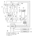
図7はブロック回路構成図を示し、図1〜図6で説明したレンズ鏡筒2の構成要素については、同一の符号を付している。第1レンズユニットL1、第2レンズユニットL2、第3a、3bレンズサブユニットL3a、L3b、第4レンズユニットL4のレンズ群の結像面に配置された撮像素子8の出力は、カメラ信号処理回路21に接続され、このカメラ信号処理回路21の出力はAEゲート22、AFゲート23に並列的に接続され、AEゲート22の出力は直接に、AFゲート23の出力はAF信号処理回路24を介して、カメラの制御を行う制御回路25に接続されている。
FIG. 7 is a block circuit configuration diagram, and the same reference numerals are given to the components of the
また制御回路25には、第2レンズユニットL2の駆動源であるステッピングモータ7a、第4レンズユニットL4の駆動源であるボイスコイルモータ26、光量調節ユニット11の駆動源である絞りモータ27、第2レンズユニットL2が光軸方向における基準位置に位置しているか否かを検出するズームリセットスイッチ7f、絞りエンコーダ28、MRセンサ10d、電磁コイル3p、ズームスイッチ29、ズームトラッキングメモリ30、ピッチ方向振れセンサ31、ヨー方向振れセンサ32が接続されている。
The
第2レンズユニットL2が基準位置に位置したことを検出した後に、ステッピングモータ7aに入力するパルス信号数を連続して計数することにより、第2レンズユニットL2の光軸方向の基準位置に対する移動量の検出を行うことができる。絞りエンコーダ28は絞りモータ27内にホール素子を配置し、ロータとステータの回転位置関係を検出する方式のものなどが用いられる。
After detecting that the second lens unit L2 is positioned at the reference position, the amount of movement of the second lens unit L2 relative to the reference position in the optical axis direction is continuously counted by counting the number of pulse signals input to the stepping
カメラ信号処理回路21は撮像素子8からの出力に対して所定の増幅やガンマ補正などの信号処理を施し、これらの処理を受けた映像信号のコントラスト信号は、AEゲート22、AFゲート23に供給される。AEゲート22、AFゲート23は、それぞれ露出制御及びピント合わせのために最適な信号の取出範囲を全画面の映像信号の中から設定する。AEゲート22、AFゲート23の大きさは可変であったり、複数個設けられたりする場合がある。AF(オートフォーカス)のためのAF信号を処理するAF信号処理回路24は、映像信号の高周波成分に関する1つ又は複数の出力を生成する。
The camera
ズームトラッキングメモリ30は変倍に際して、被写体距離と第2レンズユニットL2の位置に応じた第4レンズユニットL4の位置情報を記憶している。なお、このズームトラッキングメモリ30は制御回路25内のメモリを使用してもよい。
The
例えば、撮影者によりズームスイッチ29が操作されると、制御回路25はズームトラッキングメモリ30の情報を基に算出した第2レンズユニットL2と第4レンズユニットL4の所定の位置関係が保たれるように、現在の第2レンズユニットL2の光軸方向の絶対位置を示す計数値と算出された第2レンズユニットL2のセットすべき位置とが一致する。また、現在の第4レンズユニットL4の光軸方向の絶対位置を示す計数値と、算出された第4レンズユニットL4のセットすべき位置とが一致するように、ステッピングモータ7aとボイスコイルモータ26の駆動を制御する。
For example, when the photographer operates the
またAF動作では、制御回路25はAF信号処理回路24の出力がピークを示すように、ボイスコイルモータ26の駆動を制御する。更に、適正露出を得るために、制御回路25はAEゲート22を通過したY信号の出力の平均値を基準値として、絞りエンコーダ28の出力がこの基準値となるように、絞りモータ27の駆動を制御し光量を制御する。
In the AF operation, the
制御回路25はピッチ方向振れセンサ31、ヨー方向振れセンサ32からの出力と、MRセンサ10dからの信号に基づいて、電磁コイル3pへの通電を制御して、第3レンズユニットL3を駆動し像振れを補正する。
The
このように、本実施例では光量調節ユニット11の前後に配置された第3aレンズサブユニットL3aと第3bレンズサブユニットL3bを光軸直交方向に駆動して像振れ補正を行う。このとき、シフトユニット部3の駆動部であるマグネット3jや前ヨーク3oは、被駆動部である第3aレンズサブユニットL3aと第3bレンズサブユニットL3bよりも前玉側に位置し、なお第2レンズユニットL2の外側に位置している。
Thus, in this embodiment, the image blur correction is performed by driving the third-a lens subunit L3a and the third-b lens subunit L3b arranged before and after the light
即ち本実施例では、従来では被駆動部の真横に配置していた振れ補正のための駆動部を、光軸方向前側に配置することによって、径方向の大きさを大きくすることなく、つまり光量調節ユニット11よりも外側に駆動部を配置することなく、従来通りの変倍作用を行うことができる。なお、第2レンズユニットL2と第3aレンズサブユニットL3aとを接近させてもよい。
In other words, in this embodiment, the shake correction driving unit, which has been conventionally arranged directly beside the driven unit, is arranged on the front side in the optical axis direction without increasing the size in the radial direction, that is, the light quantity. A conventional zooming operation can be performed without disposing the drive unit outside the
これにより、ズームレンズ光学系の全長を長くすることなく、また径方向も大きくすることなく、像振れ補正装置を搭載した小型の光学機器を実現することができる。 Thereby, it is possible to realize a small optical device equipped with the image blur correction device without increasing the overall length of the zoom lens optical system and without increasing the radial direction.
上述の実施例では、ムービングマグネット型のアクチュエータを用いて第3レンズユニットL3を駆動する場合について説明したが、コイルを第3レンズユニットL3側に設け、マグネットをシフトベース3a側に設けたムービングコイル型のアクチュエータを用いる場合にも適用することができる。
In the above-described embodiment, the case where the third lens unit L3 is driven using a moving magnet type actuator has been described. However, the moving coil has a coil provided on the third lens unit L3 side and a magnet provided on the
また実施例では、第3aレンズサブユニットL3aと第3bレンズサブユニットL3bを一体的に光軸直交方向に駆動する場合について説明したが、第3aレンズサブユニットL3aと第3bレンズサブユニットL3bとを別々に独立して駆動するようにしてもよい。この場合には、第3aレンズサブユニットL3aと第3bレンズサブユニットL3bに対して、別々の駆動用アクチュエータを設けることになる。 In the embodiment, the case where the 3a lens subunit L3a and the 3b lens subunit L3b are integrally driven in the optical axis orthogonal direction has been described. However, the 3a lens subunit L3a and the 3b lens subunit L3b are combined. You may make it drive independently separately. In this case, separate driving actuators are provided for the 3a lens subunit L3a and the 3b lens subunit L3b.
更に実施例では、レンズ鏡筒がカメラ本体に一体的に設けられた撮像装置について説明したが、本発明はカメラ本体に対して着脱可能な交換レンズ装置や、防振機能を有する双眼鏡等の観察機器等の光学機器にも適用することができる。 Further, in the embodiment, the imaging apparatus in which the lens barrel is integrally provided in the camera body has been described. However, the present invention is an observation of an interchangeable lens apparatus that can be attached to and detached from the camera body, binoculars having a vibration isolation function, and the like The present invention can also be applied to optical equipment such as equipment.
1 カメラ本体
2 レンズ鏡筒
3 シフトユニット部
4 前玉鏡筒
5 固定鏡筒
6 後部鏡筒
7 バリエータ移動枠
8 撮像素子
10 フォーカス移動枠
11 光量調節ユニット
L2 第2レンズユニット
L3 第3レンズユニット
L3a 第3aレンズサブユニット
L3b 第3bレンズサブユニット
L4 第4レンズユニット
DESCRIPTION OF
Claims (2)
前記第1及び第2の補正レンズを一体的に連結する連結部を有し前記第1及び第2の補正レンズを保持する第1のレンズ移動枠と、
像振れを補正するために光軸に垂直な平面内で前記第1のレンズ移動枠を移動させ、前記光軸方向において前記連結部よりも物体側に配置されたコイルとマグネットとを含む駆動手段と、
前記第1の補正レンズよりも物体側に配置され前記光軸方向に移動して変倍を行う変倍レンズと、
前記変倍レンズを保持する第2のレンズ移動枠と、を有し、
前記光軸方向から見た場合に前記コイルと前記マグネットと前記連結部とが重なっており、
前記コイルと前記マグネットとのうち一方が前記第1のレンズ移動枠に固定され、他方が前記第1のレンズ移動枠を前記光軸に垂直な平面内で移動可能に支持するベース部材に固定され、前記コイルと前記マグネットとのうち少なくとも何れかが前記第1の補正レンズよりも物体側に配置され、
前記第2のレンズ移動枠が像面側に移動した際に、前記変倍レンズの一部が前記光軸に垂直な平面内において前記第1の補正レンズよりも物体側に配置された前記コイルと前記マグネットとのうち少なくとも何れかと重なるようにしたことを特徴とする光学機器。 A first correction lens disposed on the object side and a second correction lens disposed on the image plane side across the light amount adjustment unit in the optical axis direction;
A first lens moving frame having a connecting portion for integrally connecting the first and second correction lenses and holding the first and second correction lenses;
Driving means including a coil and a magnet that move the first lens moving frame in a plane perpendicular to the optical axis in order to correct image blur, and are disposed on the object side of the connecting portion in the optical axis direction. When,
A zoom lens that is disposed closer to the object side than the first correction lens and moves in the optical axis direction for zooming;
A second lens moving frame for holding the zoom lens,
When viewed from the optical axis direction, the coil, the magnet, and the connecting portion overlap,
One of the coil and the magnet is fixed to the first lens moving frame, and the other is fixed to a base member that supports the first lens moving frame movably in a plane perpendicular to the optical axis. , At least one of the coil and the magnet is disposed closer to the object side than the first correction lens,
When the second lens moving frame moves to the image plane side, the part of the variable power lens is disposed on the object side of the first correction lens in a plane perpendicular to the optical axis. And at least one of the magnet and an optical device.
Priority Applications (2)
| Application Number | Priority Date | Filing Date | Title |
|---|---|---|---|
| JP2004318120A JP4750402B2 (en) | 2004-11-01 | 2004-11-01 | Optical equipment |
| US11/258,329 US7460775B2 (en) | 2004-11-01 | 2005-10-25 | Optical apparatus including efficiently arranged shake correction means |
Applications Claiming Priority (1)
| Application Number | Priority Date | Filing Date | Title |
|---|---|---|---|
| JP2004318120A JP4750402B2 (en) | 2004-11-01 | 2004-11-01 | Optical equipment |
Publications (3)
| Publication Number | Publication Date |
|---|---|
| JP2006126718A JP2006126718A (en) | 2006-05-18 |
| JP2006126718A5 JP2006126718A5 (en) | 2007-12-20 |
| JP4750402B2 true JP4750402B2 (en) | 2011-08-17 |
Family
ID=36262031
Family Applications (1)
| Application Number | Title | Priority Date | Filing Date |
|---|---|---|---|
| JP2004318120A Expired - Fee Related JP4750402B2 (en) | 2004-11-01 | 2004-11-01 | Optical equipment |
Country Status (2)
| Country | Link |
|---|---|
| US (1) | US7460775B2 (en) |
| JP (1) | JP4750402B2 (en) |
Families Citing this family (17)
| Publication number | Priority date | Publication date | Assignee | Title |
|---|---|---|---|---|
| JP5011793B2 (en) * | 2006-04-05 | 2012-08-29 | 株式会社ニコン | Lens barrel and imaging device |
| JP5159090B2 (en) * | 2006-11-13 | 2013-03-06 | キヤノン株式会社 | Optical equipment |
| JP5197035B2 (en) * | 2008-01-22 | 2013-05-15 | キヤノン株式会社 | Lens barrel and imaging device |
| US8482871B2 (en) | 2008-08-21 | 2013-07-09 | Nikon Corporation | Lens barrel and image capturing device |
| WO2010021150A1 (en) * | 2008-08-21 | 2010-02-25 | 株式会社ニコン | Lens barrel and imaging device |
| JP5093036B2 (en) * | 2008-10-02 | 2012-12-05 | 株式会社ニコン | Lens barrel and imaging device |
| KR101300353B1 (en) * | 2011-12-22 | 2013-08-28 | 삼성전기주식회사 | Hand vibration correction device |
| RU2497164C1 (en) * | 2012-05-24 | 2013-10-27 | Федеральное государственное бюджетное образовательное учреждение высшего профессионального образования "Санкт-Петербургский национальный исследовательский университет информационных технологий, механики и оптики" | Method of adjusting microscope lens and microscope lens |
| JP6185334B2 (en) * | 2013-08-20 | 2017-08-23 | 惠州市大亜湾永昶電子工業有限公司 | Lens drive device |
| US9659629B2 (en) * | 2015-03-27 | 2017-05-23 | SK Hynix Inc. | Sense amplifier driving device |
| JP6833504B2 (en) * | 2016-12-27 | 2021-02-24 | キヤノン株式会社 | Shake correction device and lens device and imaging device using this |
| TWM564733U (en) | 2017-03-08 | 2018-08-01 | 大陸商光寶電子(廣州)有限公司 | Camera module and portable electronic device |
| JP7270502B2 (en) * | 2019-08-09 | 2023-05-10 | ニデックインスツルメンツ株式会社 | Optical unit with anti-shake function |
| EP4040923A1 (en) * | 2019-11-14 | 2022-08-10 | Nanchang O-Film Optical-Electronic Tech Co., Ltd | Circuit board, camera module, and mobile terminal |
| CN116320750A (en) * | 2022-03-31 | 2023-06-23 | 常州市瑞泰光电有限公司 | Vibration isolation device and imaging device |
| CN117203972A (en) * | 2022-04-02 | 2023-12-08 | 北京小米移动软件有限公司 | Camera module and electronic equipment |
| CN116719196B (en) * | 2022-09-23 | 2024-06-07 | 荣耀终端有限公司 | Anti-shake electronic device and anti-shake system |
Family Cites Families (8)
| Publication number | Priority date | Publication date | Assignee | Title |
|---|---|---|---|---|
| US5680251A (en) * | 1994-01-21 | 1997-10-21 | Nikon Corporation | Lens barrel having a vibration compensation lens unit with moveable lens support member |
| US6008954A (en) * | 1996-08-30 | 1999-12-28 | Minolta Co., Ltd. | Lens barrel with optical system for preventing image shake |
| US5966248A (en) * | 1996-10-16 | 1999-10-12 | Nikon Corporation | Lens driving mechanism having an actuator |
| JP3867363B2 (en) * | 1997-08-29 | 2007-01-10 | 株式会社ニコン | Lens barrel |
| JP2002049075A (en) * | 2000-05-25 | 2002-02-15 | Fuji Photo Film Co Ltd | Diaphragm switching device for camera |
| JP4143318B2 (en) * | 2002-03-29 | 2008-09-03 | キヤノン株式会社 | Lens barrel and optical apparatus using the same |
| US7321470B2 (en) * | 2002-10-08 | 2008-01-22 | Olympus Corporation | Camera |
| JP4520253B2 (en) * | 2004-09-02 | 2010-08-04 | Hoya株式会社 | Lens barrel |
-
2004
- 2004-11-01 JP JP2004318120A patent/JP4750402B2/en not_active Expired - Fee Related
-
2005
- 2005-10-25 US US11/258,329 patent/US7460775B2/en active Active
Also Published As
| Publication number | Publication date |
|---|---|
| JP2006126718A (en) | 2006-05-18 |
| US20060093339A1 (en) | 2006-05-04 |
| US7460775B2 (en) | 2008-12-02 |
Similar Documents
| Publication | Publication Date | Title |
|---|---|---|
| JP4630565B2 (en) | Optical equipment | |
| US7460775B2 (en) | Optical apparatus including efficiently arranged shake correction means | |
| US7747149B2 (en) | Optical apparatus having image-blur correction/reduction system | |
| JP6960983B2 (en) | Imaging device with image stabilization function | |
| JP4661915B2 (en) | Image blur correction device, lens barrel device, and camera device | |
| JP4513879B2 (en) | Image blur correction device, lens barrel device, and camera device | |
| US8634138B2 (en) | Lens barrel and optical apparatus including the same | |
| JP2010048984A (en) | Optical apparatus | |
| JP5483988B2 (en) | Image blur correction device | |
| JP5294936B2 (en) | Lens barrel and optical apparatus having the same | |
| JP4871679B2 (en) | Image blur correction device, lens barrel, and imaging device | |
| JP2010243877A (en) | Optical equipment | |
| JP2010169844A (en) | Optical device | |
| JP4750452B2 (en) | Optical equipment | |
| JP2010249858A (en) | Lens barrel and imaging device having the same | |
| JP2010039083A (en) | Optical vibration-proof device and optical equipment | |
| JP5867994B2 (en) | Lens barrel and optical equipment | |
| JP2010271513A (en) | Optical vibration-proof device and optical apparatus | |
| JP2012093496A (en) | Lens barrel and optical equipment including the same | |
| JP2007034125A (en) | Optical equipment | |
| JP7258699B2 (en) | Lens barrels and optical equipment | |
| JP2009210922A (en) | Image blur correction unit, lens barrel device, and imaging apparatus | |
| JP2010008982A (en) | Lens barrel and method for assembling lens barrel | |
| JP2010164985A (en) | Image blur correction device, lens barrel device, and camera device | |
| JP2013109001A (en) | Lens barrel and imaging device |
Legal Events
| Date | Code | Title | Description |
|---|---|---|---|
| A521 | Request for written amendment filed |
Free format text: JAPANESE INTERMEDIATE CODE: A523 Effective date: 20071026 |
|
| A621 | Written request for application examination |
Free format text: JAPANESE INTERMEDIATE CODE: A621 Effective date: 20071026 |
|
| RD01 | Notification of change of attorney |
Free format text: JAPANESE INTERMEDIATE CODE: A7421 Effective date: 20100218 |
|
| RD01 | Notification of change of attorney |
Free format text: JAPANESE INTERMEDIATE CODE: A7421 Effective date: 20100630 |
|
| A131 | Notification of reasons for refusal |
Free format text: JAPANESE INTERMEDIATE CODE: A131 Effective date: 20100907 |
|
| A521 | Request for written amendment filed |
Free format text: JAPANESE INTERMEDIATE CODE: A523 Effective date: 20101022 |
|
| A02 | Decision of refusal |
Free format text: JAPANESE INTERMEDIATE CODE: A02 Effective date: 20110111 |
|
| A521 | Request for written amendment filed |
Free format text: JAPANESE INTERMEDIATE CODE: A523 Effective date: 20110411 |
|
| A911 | Transfer to examiner for re-examination before appeal (zenchi) |
Free format text: JAPANESE INTERMEDIATE CODE: A911 Effective date: 20110419 |
|
| TRDD | Decision of grant or rejection written | ||
| A01 | Written decision to grant a patent or to grant a registration (utility model) |
Free format text: JAPANESE INTERMEDIATE CODE: A01 Effective date: 20110517 |
|
| A01 | Written decision to grant a patent or to grant a registration (utility model) |
Free format text: JAPANESE INTERMEDIATE CODE: A01 |
|
| A61 | First payment of annual fees (during grant procedure) |
Free format text: JAPANESE INTERMEDIATE CODE: A61 Effective date: 20110519 |
|
| R150 | Certificate of patent or registration of utility model |
Ref document number: 4750402 Country of ref document: JP Free format text: JAPANESE INTERMEDIATE CODE: R150 Free format text: JAPANESE INTERMEDIATE CODE: R150 |
|
| FPAY | Renewal fee payment (event date is renewal date of database) |
Free format text: PAYMENT UNTIL: 20140527 Year of fee payment: 3 |
|
| LAPS | Cancellation because of no payment of annual fees |