JP4749734B2 - Particle source with selectable beam current and energy spread - Google Patents
Particle source with selectable beam current and energy spread Download PDFInfo
- Publication number
- JP4749734B2 JP4749734B2 JP2005039607A JP2005039607A JP4749734B2 JP 4749734 B2 JP4749734 B2 JP 4749734B2 JP 2005039607 A JP2005039607 A JP 2005039607A JP 2005039607 A JP2005039607 A JP 2005039607A JP 4749734 B2 JP4749734 B2 JP 4749734B2
- Authority
- JP
- Japan
- Prior art keywords
- lens
- aperture
- particle
- particle source
- energy
- Prior art date
- Legal status (The legal status is an assumption and is not a legal conclusion. Google has not performed a legal analysis and makes no representation as to the accuracy of the status listed.)
- Active
Links
- 239000002245 particle Substances 0.000 title claims description 80
- 230000003287 optical effect Effects 0.000 claims description 35
- 239000006185 dispersion Substances 0.000 description 18
- 238000010894 electron beam technology Methods 0.000 description 8
- 230000004075 alteration Effects 0.000 description 7
- 201000009310 astigmatism Diseases 0.000 description 4
- 150000002500 ions Chemical class 0.000 description 3
- 230000000694 effects Effects 0.000 description 2
- 230000005284 excitation Effects 0.000 description 2
- 238000000034 method Methods 0.000 description 2
- 230000010287 polarization Effects 0.000 description 2
- 206010010071 Coma Diseases 0.000 description 1
- 230000015572 biosynthetic process Effects 0.000 description 1
- 238000007599 discharging Methods 0.000 description 1
- 230000005684 electric field Effects 0.000 description 1
- 238000001493 electron microscopy Methods 0.000 description 1
- 238000000605 extraction Methods 0.000 description 1
- 238000001914 filtration Methods 0.000 description 1
- 230000001902 propagating effect Effects 0.000 description 1
- 238000001228 spectrum Methods 0.000 description 1
Images


Classifications
-
- H—ELECTRICITY
- H01—ELECTRIC ELEMENTS
- H01J—ELECTRIC DISCHARGE TUBES OR DISCHARGE LAMPS
- H01J37/00—Discharge tubes with provision for introducing objects or material to be exposed to the discharge, e.g. for the purpose of examination or processing thereof
- H01J37/02—Details
- H01J37/04—Arrangements of electrodes and associated parts for generating or controlling the discharge, e.g. electron-optical arrangement or ion-optical arrangement
- H01J37/05—Electron or ion-optical arrangements for separating electrons or ions according to their energy or mass
-
- H—ELECTRICITY
- H01—ELECTRIC ELEMENTS
- H01J—ELECTRIC DISCHARGE TUBES OR DISCHARGE LAMPS
- H01J37/00—Discharge tubes with provision for introducing objects or material to be exposed to the discharge, e.g. for the purpose of examination or processing thereof
- H01J37/02—Details
- H01J37/04—Arrangements of electrodes and associated parts for generating or controlling the discharge, e.g. electron-optical arrangement or ion-optical arrangement
- H01J37/09—Diaphragms; Shields associated with electron or ion-optical arrangements; Compensation of disturbing fields
-
- H—ELECTRICITY
- H01—ELECTRIC ELEMENTS
- H01J—ELECTRIC DISCHARGE TUBES OR DISCHARGE LAMPS
- H01J37/00—Discharge tubes with provision for introducing objects or material to be exposed to the discharge, e.g. for the purpose of examination or processing thereof
- H01J37/02—Details
- H01J37/04—Arrangements of electrodes and associated parts for generating or controlling the discharge, e.g. electron-optical arrangement or ion-optical arrangement
- H01J37/153—Electron-optical or ion-optical arrangements for the correction of image defects, e.g. stigmators
-
- H—ELECTRICITY
- H01—ELECTRIC ELEMENTS
- H01J—ELECTRIC DISCHARGE TUBES OR DISCHARGE LAMPS
- H01J37/00—Discharge tubes with provision for introducing objects or material to be exposed to the discharge, e.g. for the purpose of examination or processing thereof
- H01J37/26—Electron or ion microscopes; Electron or ion diffraction tubes
Landscapes
- Chemical & Material Sciences (AREA)
- Analytical Chemistry (AREA)
- Analysing Materials By The Use Of Radiation (AREA)
- Electron Sources, Ion Sources (AREA)
Description
本発明は、粒子源が備え付けられた粒子−光学装置に関し、その粒子源は、荷電粒子の少なくとも一つのビームを発生させるように、具現され、その粒子源には、
荷電粒子の放出用の粒子を放出する面、
粒子を放出する面の像の形成用のレンズ、
前記粒子のビームの制限用のビームを制限する絞り、及び
像の場所における、エネルギーを選択する絞り
が提供される。
The present invention relates to a particle-optical apparatus equipped with a particle source, the particle source being embodied to generate at least one beam of charged particles, the particle source comprising:
The surface from which charged particles are released,
Lenses for the formation of images of surfaces emitting particles,
An aperture for limiting the beam for limiting the beam of particles and an aperture for selecting energy at the location of the image are provided.
粒子−光学装置で用いられるこのような粒子源は、刊行物(非特許文献1)に記載されている。 Such particle sources used in particle-optical devices are described in a publication (Non-Patent Document 1).
それに記載された粒子ビームは、電子源の形態を有し、例えば、電子顕微鏡において使用され得ると共に、電子ビームに小さいエネルギーの広がりを提供することに役に立つ。例えば、電子顕微鏡において、電子ビームの小さいエネルギーの広がりは、用いられた電子−光学レンズが、そのとき、より小さい色収差を引き起こすことになり、その結果としてより高い分解能が得られるので、望ましい。 The particle beam described therein has the form of an electron source and can be used, for example, in an electron microscope and serves to provide a small energy spread to the electron beam. For example, in an electron microscope, a small energy spread of the electron beam is desirable because the electron-optical lens used will then cause less chromatic aberration, resulting in higher resolution.
色収差は、一般に、レンズが、異なるエネルギーを備えた粒子について異なる光学パワーを有するという事実によって引き起こされる。レンズ(静電的又は磁気的)は、一般に、低エネルギーの粒子に対しては、より高いエネルギーを備えた粒子に対するよりも小さい焦点距離を有することになる。色収差は、ビームにおける粒子のエネルギーの広がりに比例する。このように、より低いエネルギーの広がりは、より少ない色収差に至る。 Chromatic aberration is generally caused by the fact that the lens has different optical power for particles with different energies. A lens (electrostatic or magnetic) will generally have a smaller focal length for low energy particles than for particles with higher energy. Chromatic aberration is proportional to the spread of the energy of the particles in the beam. Thus, a lower energy spread leads to less chromatic aberration.
既知の電子源において、電子を放出する面によって発生させられた電子ビームは、ビームを制限する絞りを備えたレンズによって、電子を放出する面を、ビームを制限する面上へ結像させるような様式で、集束させられる。レンズ及び像の間に、電子ビームを、第一の偏向ユニットによって偏向させる。 In known electron sources, an electron beam generated by an electron emitting surface is imaged by the lens with a diaphragm that restricts the beam onto the surface that restricts the beam. Focused in a manner. Between the lens and the image, the electron beam is deflected by a first deflection unit.
当業者に知られているように、低エネルギーの粒子は、電気的な又は磁気的な偏向の場によって、高エネルギーの粒子についての場合よりも大きい程度に、偏向させられる。よって、このような偏向の結果として、空間的なエネルギーの分布が、起こることになる。このエネルギーの分散の結果として、レンズによって形成された像は、分散線であり、その線は、異なるエネルギーを備えた粒子の点の焦点の集団であり、それによって、与えられたエネルギーを備えた電子は、分散線上における対応する位置を有することになる。 As is known to those skilled in the art, low energy particles are deflected by an electrical or magnetic deflection field to a greater extent than for high energy particles. Thus, a spatial energy distribution occurs as a result of such deflection. As a result of this energy dispersion, the image formed by the lens is a dispersion line, which is a collection of focal points of particles with different energies, thereby providing the given energy. The electrons will have corresponding positions on the dispersion line.
分散線に対して垂直な(及びそれによって、エネルギーの分散が起こる方向に垂直な)選択スリットを据え付けることによって、そのスリットは、分散線の一部分が通過することのみを許容するが、通過した電子ビームは、通過した部分においてある一定の区間の元来のエネルギースペクトルを備えた電子のみが存在するので、減少したエネルギーの広がりを有することになる。 By installing a selection slit perpendicular to the dispersion line (and thereby perpendicular to the direction in which energy dispersion occurs), the slit only allows a portion of the dispersion line to pass, but the electrons passed The beam will have a reduced energy spread because there are only electrons with a certain section of the original energy spectrum in the passage.
続いて、ビームは、第二の偏向ユニットによって、再度逆戻りに、通過したビームが、ビームの方向に沿って延びるように、それが第一の偏向ユニットによって偏向させられる前に、偏向させられる。第一及び第二の偏光ユニットの選ばれた対称性の結果として、第一の偏光ユニットによって引き起こされたビームのエネルギーの分散を相殺することもまた可能である。
既知の粒子源は、相対的に広大な構築物である。本発明は、より小型な構築物を提供することを目的とする。 Known particle sources are relatively vast constructs. The present invention aims to provide a more compact construct.
このために、本発明による粒子源は、ビームを制限する絞りが、前記ビームが、偏心してレンズを通り抜けるビームであるような様式で、具現されることを特徴とする。 To this end, the particle source according to the invention is characterized in that the aperture limiting beam is embodied in such a way that the beam is a beam that is eccentric and passes through the lens.
本発明は、レンズの中央部分を通り抜けないが、偏心して位置させられるレンズの一部分を通り抜ける、ビームを用いることによって所望のエネルギーの分散を成し遂げることが、可能であるという洞察の上に立てられる。 The invention rests on the insight that it is possible to achieve the desired energy distribution by using a beam that does not pass through the central part of the lens but passes through a part of the lens that is positioned eccentrically.
ビームが、偏心してレンズを通り抜けるという事実の結果として、ビームにおける低エネルギーの粒子は、レンズに対して、より高いエネルギーを備えた粒子よりも近くレンズの光軸と交差することになる。その結果は、レンズが、点状の対象を、丸の像として結像させずに、代わりに分散線として結像させるということであり、その丸の像は、仮にビームが、レンズの中部を通り抜けるものであったとする場合のものであろう。分散線の場所に、分散線の一部分が通過することのみを許容するエネルギーを選択する絞りを置くことによって、通過したビームのエネルギーの広がりを、ビームに元来存在するエネルギーの広がりに関して、減少させることになる。 As a result of the fact that the beam decenters through the lens, the low energy particles in the beam will intersect the lens optical axis closer to the lens than the particles with higher energy. The result is that the lens does not image the pointed object as a circle image, but instead as a dispersive line. It would be the case of passing through. By placing a stop at the location of the dispersive line that selects an energy that only allows a portion of the dispersive line to pass, the energy spread of the beam passed through is reduced with respect to the energy spread originally present in the beam. It will be.
レンズによって形成された像は、分散線であり、それによって、この分散線の一部分は、エネルギーを選択する絞りを素通りすることを許容される。エネルギーを選択する絞りに、近似によって分散線の幅に等しい分散の方向における大きさを与えることによって、通過したビームは、みかけ上正方形の像から現れることになる。そして、このみかけの像は、任意の後の光学素子についての対象として役に立つことになる。丸の形態は、通常、後の光学素子についての対象として使用されるが、正方形の形態は、より通例の丸の対象の形態の十分な近似である。 The image formed by the lens is a dispersive line, whereby a portion of this dispersive line is allowed to pass through an aperture that selects energy. By giving the aperture that selects the energy a size in the direction of dispersion equal to the width of the dispersion line by approximation, the passed beam will appear from an apparently square image. This apparent image will then serve as an object for any subsequent optical element. The round form is usually used as an object for later optical elements, but the square form is a sufficient approximation of the more usual round object form.
偏心のビームの助けにより作られた像は、光軸の外側に形成される。これは、レンズの球面収差によって引き起こされ、その収差は、それ自体を、レンズの中部から遠くでレンズを通り抜けるビームに対して、レンズが、レンズの中央部分を通り抜けるビームに対するよりも大きい光学パワーを有するということで特徴付ける。粒子を放出する面の像が、レンズの光軸の外側に形成されるので、エネルギーを選択する絞りもまた、従って、その軸上に置かれる必要がないことになる。 An image created with the aid of an eccentric beam is formed outside the optical axis. This is caused by the spherical aberration of the lens, which itself has a greater optical power for a beam that passes through the lens far from the middle of the lens than for a beam that passes through the central part of the lens. Characterize by having. Since the image of the surface emitting the particles is formed outside the optical axis of the lens, the energy-selecting aperture will therefore not have to be placed on that axis.
ビームを制限する絞りを、レンズの前に、レンズの中に、又はレンズの後に、置くことができることは、指摘されるべきである。偏心のビームが、レンズを横切るときのように、依然として制限されないこともあることは、本質的ではない、結局偏心のビームを形成する粒子が、レンズの偏心して位置させられた部分を通り抜けることのみが、本質的である。 It should be pointed out that a diaphragm limiting the beam can be placed in front of, in the lens or after the lens. It is not essential that the decentered beam is still unrestricted, as when traversing the lens, but the particles that eventually form the decentered beam only pass through the decentered part of the lens. Is essential.
本発明による粒子源の別の実施形態において、ビームを制限する絞りもまた、レンズの中部を通り抜けるビームが通過することを許容するように、具現される。 In another embodiment of the particle source according to the present invention, the aperture limiting beam is also implemented to allow the beam passing through the middle of the lens to pass.
例えば、電子顕微鏡において粒子源を使用する際に、しばしば、例えば一つの観察の状況において、その性質を選択することができるビーム、エネルギーの減少についての要求なしに相対的に大きい電流を備えたビーム、及び別の観察の情況において、大きい電流についての要求なしに減少したエネルギーの広がりを備えたビームについての要求がある。そして、それは、粒子源が、必要に応じてビームの両方のタイプの各々を発生させることができるとすれば、好都合である。 For example, when using a particle source in an electron microscope, often a beam whose properties can be selected, for example in one observation situation, a beam with a relatively large current without the need for energy reduction In other observational situations, there is a need for a beam with reduced energy spread without the need for large currents. And it is advantageous if the particle source can generate each of both types of beams as needed.
この要求は、偏心のビームに加えて、今また、中央のビーム、すなわち、レンズの中部を通じたビームが、相対的に大きい電流を伴って、通過することを許容することによって、満足させられる。相対的に大きい電流は、偏心のビームの場合におけるビームを制限する絞りの絞り開口よりも大きいようにこの中央のビームの場合におけるビームを制限する絞りの絞り開口を選ぶことによって、達成される。もちろん、絞り開口のより大きい直径は、ビームのより大きい開口の角度、従って、より大きい電流を暗示する。 This requirement is met by allowing the central beam, ie the beam through the middle of the lens, to pass through with a relatively large current, in addition to the eccentric beam. A relatively large current is achieved by choosing a stop aperture that limits the beam in the case of this central beam so that it is larger than the stop aperture that limits the beam in the case of an eccentric beam. Of course, the larger diameter of the aperture opening implies a larger opening angle of the beam and thus a larger current.
この中央のビームについては、エネルギーの減少が達成されず、空間的なエネルギーの分散を備えた分散線が形成されないように見ることは、指摘されるべきである。よって、エネルギーを選択する絞りの開口は、中央のビームの場合には、必要でない。しかしながら、偏心のビームについて存在するエネルギーを選択する絞りの空間的な範囲は、中央のビームが、妨害されないで通過することを許容されるような様式で、選ばれるべきである。これは、先ごろ説明したように、偏心のビームから導かれる像が、軸の上にないので、可能であり、従って、偏心のビームについてのエネルギーを選択する絞りが、光軸と同じくらい遠くに延びる必要がない。 It should be pointed out that for this central beam it is seen that no energy reduction is achieved and no dispersion line with spatial energy dispersion is formed. Thus, the aperture of the diaphragm for selecting energy is not necessary for the central beam. However, the spatial extent of the iris that selects the energy present for the eccentric beam should be chosen in such a way that the central beam is allowed to pass unimpeded. This is possible because, as explained earlier, there is no image derived from the eccentric beam on the axis, so the diaphragm that selects the energy for the eccentric beam is as far away as the optical axis. There is no need to extend.
中央のビームで作られた像が、レンズの励起の場合には、偏心のビームの助けにより形成された像よりもレンズから幾分遠くにあることになるが、この効果について補正することは、望みであれば、レンズの光学パワーを緩やかに変動させることによって、可能である。 In the case of lens excitation, the image created with the central beam will be somewhat further from the lens than the image formed with the help of an eccentric beam, but correcting for this effect is If desired, this is possible by gently varying the optical power of the lens.
さらに別の実施形態においては、本発明による粒子源には、偏向ユニットが提供され、その偏向ユニットは、光軸に向かって荷電粒子のビームの一つを、このビームが光軸のまわりでさらに伝播するような様式で、偏向させるように、具現される。 In yet another embodiment, the particle source according to the invention is provided with a deflection unit, which deflection unit further emits one of the beams of charged particles towards the optical axis, said beam further around the optical axis. It is embodied to deflect in a propagating manner.
この実施形態は、電流及びエネルギーの広がりに関して異なる性質を備えた、異なるビームついての要求があるとすれば、特に魅力的である。ビームは、中央のビーム及び一つ以上の偏心のビームを含んでもよい。これを、数個のビームを制限する絞り及び数個のエネルギーを選択する絞りの両方を適用することによって、達成することができる。エネルギーの広がりにおける差を、エネルギーを選択する絞りにおける絞り開口の直径を、異なるものであるように選ぶことによって成し遂げることができるのに対して、電流における所望の差は、ビームを制限する絞りにおける絞り開口の直径を、異なるものであるように選ぶことによって達成される。 This embodiment is particularly attractive if there is a need for different beams with different properties with respect to current and energy spread. The beams may include a central beam and one or more eccentric beams. This can be achieved by applying both a diaphragm that restricts several beams and a diaphragm that selects several energies. Differences in energy spread can be achieved by choosing different aperture aperture diameters in the energy-selecting aperture, whereas the desired difference in current is achieved in the aperture-limiting aperture. This is achieved by choosing the diameter of the aperture opening to be different.
例えば、電子顕微鏡において本発明による粒子源を使用するとき、ビームの一つが選択される。選択されたビームを、これが、それ自体知られている後の光学素子についての光軸のまわりで利用可能であるような様式で、扱うことが望まれる。これを、エネルギーを選択する絞りの付近に偏向ユニットを置くことによって、達成することができる。選択されたビームは、光軸に向かって偏向ユニットによって偏向させられ、それによって他の選択されないビームは、光軸のまわりのある場所の中へもたらされない。これらの選択されないビームを、偏向ユニットの後部に置かれた絞りによって遮断することができる。 For example, when using a particle source according to the invention in an electron microscope, one of the beams is selected. It is desired to handle the selected beam in such a way that it is available around the optical axis for later optical elements known per se. This can be achieved by placing a deflection unit in the vicinity of the diaphragm that selects the energy. The selected beam is deflected by the deflection unit towards the optical axis, so that no other non-selected beam is brought into some place around the optical axis. These unselected beams can be interrupted by a stop placed at the rear of the deflection unit.
偏向ユニット及びレンズを、静電的なもの又は磁気的なものであるように、具現してもよいことは、指摘されるべきである。純粋に静電的な実施形態は、粒子源が、イオン源であるとき、好都合であり、電場でイオンを集束させると共に偏向させることが、磁場でイオンを集束させると共に偏向させるよりも容易であるように見る。加えて、静電レンズは、一般に、磁気レンズよりも大きい色収差を引き起こし、それは、この場合には、静電的に具現されたレンズの(所望の)エネルギーの分散が、磁気的に具現されたレンズのものよりも大きいことを意味する。 It should be pointed out that the deflection unit and the lens may be embodied to be electrostatic or magnetic. Purely electrostatic embodiments are advantageous when the particle source is an ion source, and it is easier to focus and deflect ions with an electric field than to focus and deflect ions with a magnetic field Look like. In addition, electrostatic lenses generally cause greater chromatic aberration than magnetic lenses, in which case the (desired) energy distribution of the electrostatically implemented lens is magnetically implemented. Means larger than that of the lens.
さらに別の実施形態において、粒子を放出する面は、数個の、並置されない、粒子を放出する構成要素の面の形態を有する。 In yet another embodiment, the particle emitting surface has the form of several, non-contiguous, particle emitting component surfaces.
この実施形態は、偏心の絞り開口を、軸上に置かれた粒子を放出する面によっては、もはや照明することができないほど軸から遠い位置で、レンズを通り抜けるビームを形成することが、可能であるので、好都合である。これは、一般に、粒子を放出する面が、制限された開口の角度内で粒子のみを放出するという理由である。 This embodiment makes it possible to form a beam that passes through the lens at an eccentric aperture that is far from the axis so that it can no longer be illuminated, depending on the surface emitting particles placed on the axis. It is convenient because there is. This is because, in general, the particle emitting surface emits only particles within a limited opening angle.
ビームが光軸を横切るところと実質的に同じ位置で像が形成されることを許容するために、ビームを制限する絞りを通り抜ける電子のビームは、本質的に、平行なビームであるべきである。これを、粒子を放出する構成要素の面の各々の付近に補助レンズを、粒子を放出する構成要素の面を、この補助レンズの焦点面に位置させるような様式で、置くことによって、達成することができる。 In order to allow an image to be formed at substantially the same location as the beam crosses the optical axis, the electron beam that passes through the aperture limiting beam should be essentially a parallel beam. . This is accomplished by placing an auxiliary lens near each of the particle emitting component surfaces in such a manner that the particle emitting component surface is located in the focal plane of the auxiliary lens. be able to.
粒子を放出する構成要素の面に、別の位置だけでなく光軸に関して別の方向性もまた、すなわち、ビームが光軸に平行な軸のまわりの対称性を明示しないように、与えることが、可能であることは、指摘されるべきである。 It is possible to give the surface of the component emitting the particles not only another position but also another direction with respect to the optical axis, i.e. so that the beam does not manifest symmetry about an axis parallel to the optical axis. It should be pointed out that it is possible.
本発明を、図に基づいてさらに記載することにするが、それによって同一の符号は、対応する要素を示す。 The invention will be further described on the basis of the figures, whereby the same reference numerals denote corresponding elements.
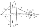
図1は、断面において、本発明による粒子源を概略的に示す。電子の場の放出源の電子を放出する面1のような粒子を放出する面は、光軸2上に位置させられる。電子を放出する面1から放たれる電子のビーム11は、丸の穴4及び5の形態におけるビームを制限する絞りの開口を含む絞り3によって、中央のビーム12及び偏心のビーム13に細分される。ビーム12及び13の両方は、光軸2に置かれたレンズ6によって集束させられる。電子を放出する面1は、ビーム12を介して像14を形成すると共にビーム13を介して像15を形成するために、レンズ6によって結像させられる。エネルギーを選択する絞りの開口9は、絞り7に位置させられ、その絞り7においては、中央のビーム12が通過することを許容するために、切欠8もまた作られる。ビーム13が軸を通り抜ける位置の付近に、偏向ユニット10が置かれ、そのユニットは、光軸2のまわりにビーム(12、13)の一つを偏向させる。
FIG. 1 schematically shows a particle source according to the invention in cross section. A surface emitting particles, such as the surface 1 emitting electrons of the electron field emission source, is located on the
電子を放出する面1は、ビーム11の中に電子を放出する。このビーム11は、絞り開口4及び偏心して位置させられた絞り開口5の両方を照明するが、その絞り開口4は、光軸2のまわりで中央に位置させられる。絞り開口4及び5は、絞り3における丸の切欠として具現される。場の放出源の場合には、この絞り3もまた、抽出電極として役に立つことができ、それによって電圧の差が、絞り3及び電子を放出する面1の間に印加される。絞り開口4及び5の大きさは、ビーム12及び13における電流を決定する。絞り開口5の偏心率は、偏心のビーム13のエネルギーの分散を決定する。
The surface 1 emitting electrons emits electrons into the beam 11. This beam 11 illuminates both the
絞り開口4によって形成された中央のビーム12は、光軸2のまわりに位置させられたレンズ6によって集束させられ、それによって電子を放出する面1の像14は、形成される。同様に、偏心のビーム13は、集束させられ、それによって電子を放出する面の像15(分散線)が、形成される。
The
図2は、絞り7の立面図を示し、その図において、絞り開口(8、9)は、中央のビーム12及び偏心のビーム13が通過することを許容するために、切り出しされてある。
FIG. 2 shows an elevation view of the diaphragm 7, in which the diaphragm apertures (8, 9) are cut out to allow the
図2は、絞り7、すなわち、絞りがその源の側から見えるものの立面図を示す。光軸のまわりに位置させられた、中央のビーム12は、絞り7における切欠によって形成された絞り開口8を横切る。レンズ6は、偏心のビーム13を集束させ、それによって、電子を放出する面1の像15が、絞り7に形成される。
FIG. 2 shows an elevational view of the diaphragm 7, ie the diaphragm visible from its source side. A
レンズ6の色収差の結果として、電子を放出する面1の像15は、径方向に分散線の中へ伸ばされる。結果として、レンズ6が、高いエネルギーを備えた電子について、それが低いエネルギーを備えた電子についてするよりも少ない効力の屈折の効果を明示するので、公称よりも高いエネルギーを備えた電子を、光軸2から、公称よりも低いエネルギーを備えた電子よりも遠くに位置させることになる。
As a result of the chromatic aberration of the
今、このビーム13の一部分のみが通過することを許容することによって、通過したビーム16は、絞り7に入射するビーム13よりも小さいエネルギーの広がりを有することになる。これは、径方向における像15の長さよりも小さい、径方向における寸法を、絞り開口9に付与することによって、達成される。
Now, by allowing only a part of this
例えば、電子顕微鏡において、電子源で形成された様々な像が、おおよそ丸である形態を有することは、望ましい。電子源の線様の像は、人為構造を引き起こし得る。接線方向における像15の幅におおよそ等しい径方向における寸法を、絞り開口9に付与することによって、通過したビーム16における電子は、像15のおおよそ正方形の部分から現れることになり、その像は、通常、丸の形態の十分な近似であるように、蒸散することになる。
For example, in an electron microscope, it is desirable that the various images formed with the electron source have a form that is approximately round. A line-like image of an electron source can cause artifacts. By providing the
接線方向における像15の幅が、レンズ6の倍率を乗じた電子を放出する面1の(みかけの)大きさに等しいので、それは、レンズ6によって形成されるような電子を放出する面1の像15が、拡大された像であるとすれば、好都合である。
Since the width of the
絞り開口9が、最も高い電子密度を備えた像15の部分が通過することを許容することは、望ましく、これが、通過したビーム16における最も高い電流に帰着することになるように見える。従って、像15が、例えば、絞り7の源側に位置決めされた偏向ユニットの助けにより、絞り開口9にわたって可動であることが、望まれる。
It is desirable for the
ビーム13が、偏心してレンズを通り抜けるので、像15の場所で分散線を一緒に形成する点の焦点は、非点収差に悩まされることになる。この非点収差を、非点収差補正装置のユニットの助けにより相殺することができる。魅力的な実施形態は、偏向ユニットを非点収差補正装置のユニットと組み合わせることであるが、その偏向ユニットは、絞り開口9にわたってビーム13を移動させるために使用される。
Since the
絞り開口9にわたってビーム15を移動させるための偏向ユニットの使用に加えて、他の方法もまた、例えば、電子を放出する面1、レンズ6、若しくは絞り7を機械的に変位させる又は穏やかにレンズ6の焦点をずらすことによって、使用することができる。
In addition to the use of a deflection unit to move the
また、像15の場所で分散線を一緒に形成する点の焦点は、コマ、回折などのような、さらなる誤差で悩まされる。レンズにおけるビームの与えられた偏心率については、ビーム13の開口の角度の適切な選択の手段によって、結果として生じる分散線が、エネルギーの分散の方向において、それに対して垂直な方向におけるものよりもたいへん大きい範囲を有するような程度まで、これらの誤差を減少させることは、可能である。この様式では、絞りの開口9の助けにより、有効なエネルギーのフィルター処理を達成することは、可能である。
Also, the focal point of the points that together form the dispersion line at the location of the
絞り7によって通過することが許容されるビーム12及び16を、例えば、それ自体知られた技術を使用して、分析されるものである試料上に集束させることができる。それによって、試料上に集束されるビームが、光軸2のまわりで中央に置かれることは、一般に重要なことである。これは、偏向ユニット10によって達成され、そのユニットは、適切な励起の手段によって、光軸2のまわりにビーム16又はビーム12のいずれかを偏向させることができる。
The
一つの偏心のビームのみを描くが、絞り3における数個の偏心の絞りの開口及び絞り7における数個のエネルギーを選択する絞りの開口を切り出すことによって、数個の偏心のビームを形成することが可能であり、それによって偏向ユニット10が、光軸2のまわりにこれらのビームの一つを偏向させることは、指摘されるべきである。
Drawing only one eccentric beam, but forming several eccentric beams by cutting out several eccentric apertures in the
図3は、本発明による粒子源を示し、それによって、粒子を放出する面が、数個の、並置されない、粒子を放出する構成要素の面の形態をとる。 FIG. 3 shows a particle source according to the invention, whereby the particle emitting surface takes the form of several non-collocated, particle emitting component surfaces.
図3は、粒子を放出する構成要素の面1−1,…,1−Nの数Nを示し、それらの面は、一般に、1−iによって示される。例えば、不連続の、電子を放出する場の放射体の形態における、これらの粒子を放出する構成要素の面1−iは、各々、電子のそれ自身のビーム11−iを生じさせる。これらのビーム11−iの各々は、それ自身のビームを制限する絞りの開口5−iによって制限される。 FIG. 3 shows the number N of the faces 1-1,..., 1-N of the component emitting the particles, which faces are generally indicated by 1-i. For example, the surface 1-i of these particle emitting components, in the form of a discontinuous, electron emitting field emitter, each produces its own beam 11-i of electrons. Each of these beams 11-i is limited by a stop aperture 5-i that limits its own beam.
この実施形態は、それが、偏心の絞り開口5−iを、軸2上に置かれた粒子を放出する面によって、もはや照明することができないほど軸2から遠い場所でレンズ6を通り抜けるビーム11−iを形成する可能性を提供するという点で、好都合である。これは、粒子を放出する面が、一般に、制限された開口の角度内で粒子を放出するという理由である。
In this embodiment, the beam 11 passes through the
ビーム13−iが光軸を横切る場所と実質的に同じ位置で像15−iを形成するために、レンズ6に入射する電子のビーム11−iは、本質的に、平行なビームであるべきである。これを、電子を放出する構成要素の面1−iの各々の付近に補助レンズ17−iを、電子を放出する構成要素の面1−iが、この補助レンズ17−iの焦点面に位置させられるような様式で、置くことによって、達成することができる。
In order to form the image 15-i at substantially the same location where the beam 13-i crosses the optical axis, the electron beam 11-i incident on the
粒子を放出する構成要素の面11−iに、光軸2に関して別の位置だけでなく、別の方向性もまた、すなわち、ビーム11−iが、光軸2に平行な軸まわりの対称性を明示しないように、与えることが、可能であることは、指摘されるべきである。
[付記]
付記(1):
粒子源が備え付けられた粒子−光学装置であって、
該粒子源は、荷電粒子の少なくとも一つのビーム(16)を発生させるように、具現され、
該粒子源には、
該荷電粒子の放出用の粒子を放出する面(1)、
該粒子を放出する面(1)の像(15)の形成用のレンズ(6)、
該粒子のビームの制限用のビームを制限する絞り(3)、及び
該像(15)の場所における、エネルギーを選択する絞り(7)
が提供される粒子−光学装置において、
該ビームを制限する絞り(3)は、該ビーム(16)が、偏心して該レンズ(6)を通り抜けるビームであるような方法で具現されることを特徴とする粒子−光学装置。
付記(2):
前記ビームを制限する絞り(3)は、また、前記レンズ(6)の中部を通り抜けるビーム(12)が通過することを許容するように、具現される、付記(1)に記載の粒子−光学装置。
付記(3):
偏向ユニット(10)が提供され、
該偏向ユニット(10)は、前記荷電粒子のビーム(12、13)の一つを光軸(2)に向かって、このビームが、該光軸(2)のまわりでさらに伝播するような様式で、偏向させるように、具現される、付記(1)又は(2)に記載の粒子−光学装置。
付記(4):
前記粒子を放出する面(1)は、数個の、並置されない、粒子を放出する構成要素の面(1−i)の形態を有する、付記(1)乃至(3)のいずれか一つに記載の粒子−光学装置。
付記(5):
付記(1)乃至(4)のいずれか一つに記載の粒子−光学装置で用いられる粒子源。
On the surface 11-i of the component emitting the particles, not only another position with respect to the
[Appendix]
Appendix (1):
A particle-optical device equipped with a particle source,
The particle source is embodied to generate at least one beam (16) of charged particles;
The particle source includes
A surface (1) for emitting particles for discharging the charged particles;
A lens (6) for forming an image (15) of the surface (1) from which the particles are emitted;
A diaphragm (3) for limiting the beam for limiting the beam of the particles; and
Aperture (7) for selecting energy at the location of the image (15)
In a particle-optical device provided with
Particle-optical device, characterized in that the stop (3) for limiting the beam is embodied in such a way that the beam (16) is decentered and passes through the lens (6).
Appendix (2):
Particle-optics according to appendix (1), wherein the aperture (3) limiting the beam is also embodied to allow the beam (12) passing through the middle of the lens (6) to pass through. apparatus.
Appendix (3):
A deflection unit (10) is provided;
The deflection unit (10) is arranged such that one of the charged particle beams (12, 13) is directed towards the optical axis (2), which further propagates around the optical axis (2). The particle-optical device according to (1) or (2), wherein the particle-optical device is embodied so as to be deflected.
Appendix (4):
The particle emitting surface (1) is in any one of the appendices (1) to (3) having the form of several, not juxtaposed, particle emitting component surfaces (1-i) The described particle-optical device.
Appendix (5):
A particle source used in the particle-optical device according to any one of appendices (1) to (4).
1 電子を放出する面
2 光軸
3,7 絞り
4,5 絞り開口
6 レンズ
8 切欠
9,9−i 絞りの開口
10 偏向ユニット
11,11−i,13−i 電子のビーム
12 中央のビーム
13 偏心のビーム
14,15,15−i 像
16,16−i 通過したビーム
1−i 粒子を放出する構成要素の面
5−i ビームを制限する絞りの開口
17−i 補助レンズ
DESCRIPTION OF SYMBOLS 1
Claims (4)
前記荷電粒子の放出用の粒子を放出する表面、A surface emitting particles for the release of the charged particles;
前記粒子を放出する表面の像の形成用のレンズ、A lens for forming an image of a surface emitting said particles;
前記荷電粒子のビームの制限用のビームを制限する絞り、及びA diaphragm for limiting the beam for limiting the beam of charged particles; and
前記像の場所におけるエネルギーを選択する絞りA diaphragm for selecting energy at the location of the image
を備える、粒子源において、A particle source comprising:
前記ビームを制限する絞りは、前記ビームが、偏心して前記レンズを通り抜けるビームであるような方式で提供されたものである、粒子源。Particle source, wherein the aperture limiting beam is provided in such a way that the beam is decentered and passes through the lens.
前記ビームを制限する絞りは、また、ビームが前記レンズの中央の部分を通過することを許容するように、提供されたものである、粒子源。A particle source that restricts the beam is also provided to allow the beam to pass through a central portion of the lens.
さらに偏向ユニットを備えると共に、In addition to having a deflection unit,
前記偏向ユニットは、前記レンズの光軸に向かって前記荷電粒子のビームを、偏向させられたビームが前記光軸のまわりでさらに伝播するような様式で、偏向させるように、提供されたものである、粒子源。The deflection unit is provided to deflect the beam of charged particles toward the optical axis of the lens in such a manner that the deflected beam further propagates around the optical axis. There is a particle source.
Applications Claiming Priority (2)
| Application Number | Priority Date | Filing Date | Title |
|---|---|---|---|
| NL1025500A NL1025500C2 (en) | 2004-02-17 | 2004-02-17 | Particle source with selectable beam current and energy distribution. |
| NL1025500 | 2004-02-17 |
Publications (2)
| Publication Number | Publication Date |
|---|---|
| JP2005235767A JP2005235767A (en) | 2005-09-02 |
| JP4749734B2 true JP4749734B2 (en) | 2011-08-17 |
Family
ID=34709387
Family Applications (1)
| Application Number | Title | Priority Date | Filing Date |
|---|---|---|---|
| JP2005039607A Active JP4749734B2 (en) | 2004-02-17 | 2005-02-16 | Particle source with selectable beam current and energy spread |
Country Status (6)
| Country | Link |
|---|---|
| US (1) | US7034315B2 (en) |
| EP (1) | EP1566826B1 (en) |
| JP (1) | JP4749734B2 (en) |
| CN (1) | CN1658331B (en) |
| DE (1) | DE602005012325D1 (en) |
| NL (1) | NL1025500C2 (en) |
Families Citing this family (26)
| Publication number | Priority date | Publication date | Assignee | Title |
|---|---|---|---|---|
| EP1783811A3 (en) * | 2005-11-02 | 2008-02-27 | FEI Company | Corrector for the correction of chromatic aberrations in a particle-optical apparatus |
| JP2007335385A (en) * | 2006-06-15 | 2007-12-27 | Sadao Nomura | Aberration correction charged particle beam generating device |
| JP4920370B2 (en) * | 2006-10-30 | 2012-04-18 | 株式会社日立製作所 | Information transmission limit measurement method of transmission electron microscope and transmission electron microscope to which this measurement method is applied |
| EP2128885A1 (en) * | 2008-05-26 | 2009-12-02 | FEI Company | Charged particle source with integrated energy filter |
| EP2226830B1 (en) | 2009-03-06 | 2014-01-08 | FEI Company | Charged particle beam processing |
| EP2402475A1 (en) | 2010-06-30 | 2012-01-04 | Fei Company | Beam-induced deposition at cryogenic temperatures |
| EP2453461A1 (en) * | 2010-11-10 | 2012-05-16 | FEI Company | Charged particle source with integrated electrostatic energy filter |
| EP2511936B1 (en) | 2011-04-13 | 2013-10-02 | Fei Company | Distortion free stigmation of a TEM |
| US8592761B2 (en) | 2011-05-19 | 2013-11-26 | Hermes Microvision Inc. | Monochromator for charged particle beam apparatus |
| US8274046B1 (en) | 2011-05-19 | 2012-09-25 | Hermes Microvision Inc. | Monochromator for charged particle beam apparatus |
| US9111715B2 (en) | 2011-11-08 | 2015-08-18 | Fei Company | Charged particle energy filter |
| CN103826380B (en) * | 2014-03-13 | 2016-10-26 | 北京大学 | A kind of ion transport device |
| KR101633978B1 (en) * | 2014-06-20 | 2016-06-28 | 한국표준과학연구원 | Monochromator and charged particle apparatus with thereof |
| US9767984B2 (en) | 2014-09-30 | 2017-09-19 | Fei Company | Chicane blanker assemblies for charged particle beam systems and methods of using the same |
| CN104678543A (en) * | 2014-12-26 | 2015-06-03 | 中国科学院苏州生物医学工程技术研究所 | Incoherent light source-based optical nipper microscope |
| CN104772460B (en) * | 2015-04-17 | 2017-01-11 | 华中科技大学 | Ionized cluster beam 3D (Three-Dimensional) printing device and ionized cluster beam 3D printing method |
| US9905391B2 (en) * | 2015-04-29 | 2018-02-27 | Kla-Tencor Corporation | System and method for imaging a sample with an electron beam with a filtered energy spread |
| CN106290168A (en) * | 2015-05-18 | 2017-01-04 | 深圳迈瑞生物医疗电子股份有限公司 | Optical detecting unit, the liquid chromatography system using this optical detecting unit and liquid phase chromatography analytical method |
| JP2017020106A (en) | 2015-07-02 | 2017-01-26 | エフ・イ−・アイ・カンパニー | Adaptive beam current for high-throughput pattern formation |
| DE102015011070A1 (en) * | 2015-08-27 | 2017-03-02 | Forschungszentrum Jülich GmbH | Apparatus for correcting the longitudinal aberration of the chromatic aberration of radiation of massed particles |
| EP3203493B1 (en) * | 2016-02-02 | 2018-10-03 | FEI Company | Charged-particle microscope with astigmatism compensation and energy-selection |
| CN106861056B (en) * | 2017-01-13 | 2019-05-14 | 北京大学 | Sector electromagnet choosing can optimize and proton medical treatment power spectrum regulation device and its regulation method |
| US10410827B2 (en) | 2017-05-03 | 2019-09-10 | Fei Company | Gun lens design in a charged particle microscope |
| DE102017208005B3 (en) | 2017-05-11 | 2018-08-16 | Carl Zeiss Microscopy Gmbh | Particle source for generating a particle beam and particle-optical device |
| EP4002420A1 (en) * | 2020-11-12 | 2022-05-25 | FEI Company | Method of determining an energy width of a charged particle beam |
| US11804357B2 (en) | 2021-09-30 | 2023-10-31 | Fei Company | Electron optical module for providing an off-axial electron beam with a tunable coma |
Family Cites Families (5)
| Publication number | Priority date | Publication date | Assignee | Title |
|---|---|---|---|---|
| US3374346A (en) * | 1964-07-15 | 1968-03-19 | Hitachi Ltd | Spectroscopic electron microscope wherein a specimen is irradiated with x-rays and the electrons emitted are energy analyzed |
| NL7004207A (en) * | 1969-07-30 | 1971-02-02 | ||
| GB1416043A (en) * | 1972-01-28 | 1975-12-03 | Nasa | Electron microscope aperture system |
| NL9100294A (en) * | 1991-02-20 | 1992-09-16 | Philips Nv | LOADED PARTICLE BUNDLE DEVICE. |
| EP1150327B1 (en) | 2000-04-27 | 2018-02-14 | ICT, Integrated Circuit Testing Gesellschaft für Halbleiterprüftechnik mbH | Multi beam charged particle device |
-
2004
- 2004-02-17 NL NL1025500A patent/NL1025500C2/en not_active IP Right Cessation
-
2005
- 2005-02-11 DE DE602005012325T patent/DE602005012325D1/en active Active
- 2005-02-11 EP EP05075340A patent/EP1566826B1/en active Active
- 2005-02-15 US US11/058,695 patent/US7034315B2/en active Active
- 2005-02-16 JP JP2005039607A patent/JP4749734B2/en active Active
- 2005-02-16 CN CN200510051944.2A patent/CN1658331B/en active Active
Also Published As
| Publication number | Publication date |
|---|---|
| US7034315B2 (en) | 2006-04-25 |
| CN1658331B (en) | 2012-03-21 |
| DE602005012325D1 (en) | 2009-03-05 |
| JP2005235767A (en) | 2005-09-02 |
| EP1566826A1 (en) | 2005-08-24 |
| NL1025500C2 (en) | 2005-08-19 |
| US20050178982A1 (en) | 2005-08-18 |
| CN1658331A (en) | 2005-08-24 |
| EP1566826B1 (en) | 2009-01-14 |
Similar Documents
| Publication | Publication Date | Title |
|---|---|---|
| JP4749734B2 (en) | Particle source with selectable beam current and energy spread | |
| JP5160499B2 (en) | Charged particle source with integrated energy filter | |
| JP4368381B2 (en) | Charged particle beam energy width reduction system for charged particle beam system | |
| JP4896877B2 (en) | Aberration corrector and method for operating the aberration corrector | |
| CN110945621B (en) | System and method for compensating chromatic dispersion of a beam splitter in a single-beam or multi-beam apparatus | |
| US6489621B1 (en) | Particle beam system with a device for reducing the energy width of a particle beam | |
| US9570268B2 (en) | Electron gun, charged particle gun, and charged particle beam apparatus using electron gun and charged particle gun | |
| JP2009193963A (en) | Tem with aberration corrector and phase plate | |
| US8158939B2 (en) | High resolution gas field ion column | |
| TWI412053B (en) | A multiple beam charged particle optical system and lens structure with at lwast two electrodes | |
| JP2007128893A (en) | Corrector for correcting chromatic aberration in particle optical device | |
| JP5518128B2 (en) | Monochromator for charged particle beam device and electronic device using the same | |
| JP6192618B2 (en) | How to use the environmentally controlled transmission electron microscope | |
| CN110911259A (en) | Multi electron beam imaging apparatus with improved performance | |
| JP2004165146A (en) | Electron microscope system | |
| JP3867048B2 (en) | Monochromator and scanning electron microscope using the same | |
| JP2008192596A (en) | Achromatic mass separator | |
| KR20170140390A (en) | System and method for imaging a sample with an electron beam with filtered energy spreading | |
| JPH11195396A (en) | Corpuscular beam device having energy filter | |
| KR20210122111A (en) | Electron diffraction holography | |
| US8946650B2 (en) | Particle beam device and method for analyzing and/or treating an object | |
| JP7188910B2 (en) | Particle source and particle-optical device for generating a particle beam | |
| JP6074760B2 (en) | Electron beam irradiation device | |
| JP2008117662A (en) | Schottky electron gun and charged particle beam device mounted with schottky electron gun | |
| JP2024023157A (en) | Simple spherical aberration corrector for SEM |
Legal Events
| Date | Code | Title | Description |
|---|---|---|---|
| A621 | Written request for application examination |
Free format text: JAPANESE INTERMEDIATE CODE: A621 Effective date: 20080215 |
|
| A977 | Report on retrieval |
Free format text: JAPANESE INTERMEDIATE CODE: A971007 Effective date: 20101207 |
|
| A131 | Notification of reasons for refusal |
Free format text: JAPANESE INTERMEDIATE CODE: A131 Effective date: 20101214 |
|
| A601 | Written request for extension of time |
Free format text: JAPANESE INTERMEDIATE CODE: A601 Effective date: 20110314 |
|
| A602 | Written permission of extension of time |
Free format text: JAPANESE INTERMEDIATE CODE: A602 Effective date: 20110317 |
|
| A521 | Request for written amendment filed |
Free format text: JAPANESE INTERMEDIATE CODE: A523 Effective date: 20110323 |
|
| TRDD | Decision of grant or rejection written | ||
| A01 | Written decision to grant a patent or to grant a registration (utility model) |
Free format text: JAPANESE INTERMEDIATE CODE: A01 Effective date: 20110510 |
|
| A01 | Written decision to grant a patent or to grant a registration (utility model) |
Free format text: JAPANESE INTERMEDIATE CODE: A01 |
|
| A61 | First payment of annual fees (during grant procedure) |
Free format text: JAPANESE INTERMEDIATE CODE: A61 Effective date: 20110518 |
|
| R150 | Certificate of patent or registration of utility model |
Ref document number: 4749734 Country of ref document: JP Free format text: JAPANESE INTERMEDIATE CODE: R150 Free format text: JAPANESE INTERMEDIATE CODE: R150 |
|
| FPAY | Renewal fee payment (event date is renewal date of database) |
Free format text: PAYMENT UNTIL: 20140527 Year of fee payment: 3 |
|
| R250 | Receipt of annual fees |
Free format text: JAPANESE INTERMEDIATE CODE: R250 |
|
| R250 | Receipt of annual fees |
Free format text: JAPANESE INTERMEDIATE CODE: R250 |
|
| R250 | Receipt of annual fees |
Free format text: JAPANESE INTERMEDIATE CODE: R250 |
|
| R250 | Receipt of annual fees |
Free format text: JAPANESE INTERMEDIATE CODE: R250 |
|
| R250 | Receipt of annual fees |
Free format text: JAPANESE INTERMEDIATE CODE: R250 |
|
| R250 | Receipt of annual fees |
Free format text: JAPANESE INTERMEDIATE CODE: R250 |
|
| R250 | Receipt of annual fees |
Free format text: JAPANESE INTERMEDIATE CODE: R250 |
|
| R250 | Receipt of annual fees |
Free format text: JAPANESE INTERMEDIATE CODE: R250 |
|
| R250 | Receipt of annual fees |
Free format text: JAPANESE INTERMEDIATE CODE: R250 |
|
| R250 | Receipt of annual fees |
Free format text: JAPANESE INTERMEDIATE CODE: R250 |
|
| R250 | Receipt of annual fees |
Free format text: JAPANESE INTERMEDIATE CODE: R250 |