JP4749552B2 - Mold and press machine - Google Patents
Mold and press machine Download PDFInfo
- Publication number
- JP4749552B2 JP4749552B2 JP2001007113A JP2001007113A JP4749552B2 JP 4749552 B2 JP4749552 B2 JP 4749552B2 JP 2001007113 A JP2001007113 A JP 2001007113A JP 2001007113 A JP2001007113 A JP 2001007113A JP 4749552 B2 JP4749552 B2 JP 4749552B2
- Authority
- JP
- Japan
- Prior art keywords
- press
- communication hole
- mold
- cavity
- molding material
- Prior art date
- Legal status (The legal status is an assumption and is not a legal conclusion. Google has not performed a legal analysis and makes no representation as to the accuracy of the status listed.)
- Expired - Fee Related
Links
Images


Landscapes
- Press-Shaping Or Shaping Using Conveyers (AREA)
Description
【0001】
【発明の属する技術分野】
本発明は、成形材料をプレス加工するための金型及びプレス装置に関するものである。
【0002】
【従来の技術】
一般に金型はプレス装置に装着され、分割された金型片間に成形材料を挿入しこれをプレスして成形品を得るものである。例えば瓦用の成型品はこのようなプレス成形によって成形される。瓦成型品は一般に下型内に荒地(あらじ:粘土を方形に切断した瓦成型品の素材)をセットし、上型でプレスして成形を行う。そして、荒地は延展され粘土が金型のキャビティ内に回って所望の形状の瓦成型品を得ることができるようになっている。
このとき延展された粘土がキャビティからはみ出ないように上型と下型には互いにすり合うすり合わせ面が形成されているが、実際には大きなプレス力で成型した場合にはすり合わせ面から粘土が若干キャビティ外に漏れ、いわゆるバリを生ずることとなってしまう。また、内部に停留した空気によって変形等が生じてしまうこともあった。従って、従来では瓦用の成型品を得るためには変形等による不良品が多く出ることやバリを後で掻き取ったりすることを前提として大きなプレス力で成型を行ってきた。
【0003】
しかし、本件特許出願人の特願2000−207686号に開示したようにキャビティ内の空気を吸引することによって大きなプレス力での成型を可能とした。具体的にはキャビティ外に連通する連通孔を金型に形成し、通気孔や通気スリットを形成した厚い鋼板をこの連通孔に装着して吸引システムによってこれら通気孔や通気スリットから内部に封入された空気を吸引させるというものである。このような成型手段では鋼板が圧力に十分耐えられるため大きなプレス力で成形できるとともに粘土内の空気を効率的に排出させることができるためバリができにくく変形のない高密度の瓦成型品を得ることが可能となっている。この効果は主として従来排出されにくくキャビティ内に停滞してしまった空気を積極的に通気孔や通気スリットから排出させたことにより発揮される。
【0004】
【発明が解決しようとする課題】
しかし、このように構成しても排気とともに粘土は通気孔や通気スリットに強く押し当てられるため通気孔や通気スリットから若干の粘土かすが押し出されることだけは防止することはできない。この粘土かすは金型内に形成された通路に溜まってしまい特に吸引効率を悪くする原因となっていた。
本発明は、このような従来の技術に存在する問題点に着目してなされたものである。その目的は、粘土かすを効率的に除去することのできる金型及びプレス装置を提供することにある。
【0005】
【課題を解決するための手段】
上記課題を解決するために、請求項1に記載の発明では、複数の金型片を有し、同各金型片の内周面にはプレス加工時に交差して互いにすり合うすり合わせ面と成形材料をプレスするプレス面とプレスされた成形材料が延展されて充填される延展部とが形成され、同すり合わせ面、プレス面及び延展部とによって包囲形成される密閉型キャビティ内に成形材料を配置し同両プレス面の接近に伴って同成形材料を押圧して所望の形状の成型品をプレス成形するようにした金型において、前記少なくとも一方の金型片に形成した前記キャビティ内周面と同キャビティ外とを連通する連通孔と、同連通孔に前記キャビティに面して装着され多数の通気用小孔又は通気用スリットを穿設してなる硬質板体から構成された通気プレートと、同連通孔内に吸気を送出する吹気手段を接続するためのコネクタと、同連通孔を封塞する封塞部材とを備え、同封塞部材を付勢手段によって前記連通孔方向に常時付勢させる一方、前記吹気手段から送出される圧縮空気による内圧上昇に伴い同付勢手段の付勢力に抗して同封塞部材を後退させ前記連通孔内に溜まった成形かすの排出を行うようにしたことをその要旨とする。
また、請求項2に記載の発明では、複数の金型片より構成され、同各金型片の内周面にプレス加工時に交差して互いにすり合うすり合わせ面と成形材料をプレスするプレス面とプレスされた成形材料が延展されて充填される延展部とが形成された金型を有し、同金型のすり合わせ面、プレス面及び延展部とによって包囲形成される密閉型キャビティ内に成形材料を配置し同両プレス面の接近に伴って同成形材料を押圧して所望の形状の成型品をプレス成形するようにしたプレス装置において、前記少なくとも一方の金型片に形成した前記キャビティ内周面と同キャビティ外とを連通する連通孔と、同連通孔に前記キャビティに面して装着され多数の通気用小孔又は通気用スリットを穿設してなる硬質板体から構成された通気プレートと、同連通孔内に圧縮空気を送出する吹気手段と、同連通孔を封塞する封塞部材とを備え、同封塞部材を付勢手段によって前記連通孔方向に常時付勢させる一方、前記吹気手段から送出される圧縮空気による内圧上昇に伴い同付勢手段の付勢力に抗して同封塞部材を後退させ前記連通孔内に溜まった成形かすの排出を行うようにしたことをその要旨とする。
【0006】
これらのように構成すると、プレスに伴いプレス面によって成形材料は押圧されてプレス面間で所定形状に成形されるとともに延展され延展部に充填され延展部においても所定形状に成形される。プレス面、延展部或いはすり合わせ面に形成された連通孔に装着された通気プレートの通気用小孔又は通気用スリットからは内部空間の減少に伴い内部に封入された空気が排出されていく。通気プレートに押し当てられた成形材料は通気用小孔又は通気用スリットから一部押し出される可能性はあるが、通過の抵抗が大きいため概ね通気プレートの形状に成型される。若干押し出された成形かすは通気プレートから連通孔側に落下する。吹気手段から圧縮空気が連通孔内に送出されると連通孔内の内圧が上昇する。但し、このとき通気プレートには通気用小孔又は通気用スリットが形成されているため完全に連通孔内は密閉されているわけではない。そのため圧縮空気はこれら通気用小孔等の面積を考慮して送出される必要がある。圧縮空気により連通孔内の内圧が上昇すると常時は付勢手段によって連通孔を封塞している封塞部材がその付勢力に抗してキャビティから離間する方向に後退する。そして、成形かすは連通孔と離間した封塞部材の間から外部に排出される。
【0007】
請求項3に記載の発明では請求項2のプレス装置において、前記吹気手段は前記連通孔から側方に伸びるバイパス通路から同連通孔に吸気を送出するようにしたことをその要旨とする。また、請求項4に記載の発明では請求項2又は3のプレス装置において、前記吹気手段を吸気手段を兼ねるようにしたことをその要旨とする。
【0008】
【発明の効果】
請求項1〜3の発明では圧縮空気により連通孔内の内圧が上昇すると常時は付勢手段によって連通孔を封塞している封塞部材がその付勢力に抗してキャビティから離間する方向に後退し、成形かすは連通孔と離間した封塞部材の間から外部に排出されるため連通孔を清掃することが容易となる。
請求項4の発明では請求項2又は3の発明の効果に加え、連通孔に吸気手段を接続し吸気させるため更に速やかに空気が外部に排出されることとなる。
【0009】
【発明の実施の形態】
以下、本発明の具体的な実施の形態を図面に基づいて説明する。本実施の形態では瓦成型品用の金型、特に図14に示す瓦成型品1用の金型に応用した実施の形態について説明する。尚、本実施の形態において前後とは図8における右及び左方向をいうこととする。
図1〜図9に示すように、軒瓦成型品加工用の金型は、上型10と下型40とにより構成されている。まず、上型10について説明する。
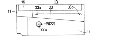
上型10は図15に示す瓦成型品1(いわゆる紐袖瓦:洋瓦の軒部分に使用するもの)の裏側(内側)の成形を行う金型である。図1及び図3に示すように、上型10は略直方体形状の上型台座11を備えている。上型台座11表面にはプレス面14が形成されている。プレス面14は瓦成型品1に応じて凹凸に形成されている。上型台座11には重量を軽減するために上方に開口する3つの穴15a〜15cが形成されている。上型台座11上方寄り前後には張り出し部16が形成されている。
【0010】
図1、図8及び図11に示すように、プレス面14には上記穴15a(図1においてもっとも手前に位置するもの)に連通する連通孔17が形成されている。連通孔17には通気筒19が嵌合されている。図9に示すように、通気筒19は筒部21とプレス面14と面一に配置される通気プレート22とより構成されている。通気プレート22にはレーザー加工で形成した多数の通気用小孔22aが穿設されている。通気用小孔15aは縦横に整然と配列され、本実施の形態1では直径0.1mmで、縦横に隣接する小孔15a同士の間隔(ピッチ)は0.8mmとされている。また、鋼の厚さはプレス面12の形状が若干湾曲しており、それに合わせて面一となるように研削されているため、一様ではないが本実施の形態では1.5〜3.2mmの間に収まっている。
【0011】
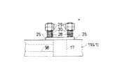
連通孔17において穴15側の開口部17aには封塞部材としての粘土かす排出バルブ25(以下、排出バルブ25とする)が配設されている。図10に示すように、排出バルブ25は連通孔17を塞ぐ封塞部材としての封塞プレート26とスライド筒27とより構成されている。封塞プレート26の中央には後述する外部の吸吹気装置84から延出された吸吹気ホース90を接続するコネクタ31が装着されている。同コネクタ31の両側には透孔26aが形成されている。スライド筒27には長孔状の切り欠き27aが形成されている。開口部17aの両側には一対の案内ボルト28が立設されており、排出バルブ25は前記通気筒19内にスライド筒27を挿入した状態で同案内ボルト28に透孔26aを挿通させており、その結果排出バルブ25は同案内ボルト28に案内されて前後にスライド可能に支持されることとなっている。各案内ボルト28の先端寄りにはナット29が螺着されている。ナット29は各案内ボルト28ごとに二重に(いわゆるダブルナット)配設され、所望の位置でナット29を固定することが可能となっている。案内ボルト28にはナット29と封塞プレート26の間に付勢手段としてのコイルスプリング30が巻回して配設されている。コイルスプリング30はナット29を基部として常時封塞プレート26を(つまり排出バルブ25を)連通孔17側に付勢している。
【0012】
図2、図3、図6及び図8に示すように、上型台座11の前後両面にはそれぞれガイド溝33が形成されている。同ガイド溝33は断面U字状とされ、同上型台座11の上端寄りに横方向に延びるように形成されている。同ガイド溝33の両端にそれぞれ注油口33a及び回収口33bが形成されている。図6に示すように、上型台座11内には連通路34が形成され注油口33a及び回収口33bと裏面側の穴15a、15cとを連通している。連通路34の裏面側開口部には潤滑油を供給・排出するための後述する圧油供給装置82から延出された注油ホース88及び回収ホース89を接続するコネクタ35が装着されている。
【0013】
次に、下型40について説明する。
下型40は図15に示す瓦成型品1(いわゆる紐袖瓦:洋瓦の軒部分に使用するもの)の表側(外側)の成形を行う金型である。図4、図5及び図7に示すように、下型40は略直方体形状の下型台座41を備えている。下型台座41表面にはプレス面44が形成されている。プレス面44は瓦成型品1に応じて凹凸に形成されている。下型台座41には重量を軽減するために下方に開口する3つの穴45a〜45cが形成されている。下型台座41の四方には側板46〜49が六角ボルト48によって固着されている。
図5に示すように、プレス面44には上記裏面側の穴45aに連通する連通孔17が形成されている。連通孔17には図9に示す通気筒19が嵌合されている。通気筒19に関する説明は前記と同様であるため省略する。
連通孔17において穴45a側の開口部17aには図10に示す封塞部材としての排出バルブ25が配設されている。排出バルブ25に関する説明は前記と同様であるため省略する。
【0014】
図4及び図5に示すように、左右の側板46,48にはガイド溝50が形成されている。同ガイド溝50は断面U字状とされ、各側板46,48の上端寄りに横方向に延びるように形成されている。同ガイド溝50の両端にそれぞれ注油口50a及び回収口50bが形成されている。図7に示すように、側板46,48内には連通路51が形成され注油口50a及び回収口50bと裏面側の穴45a、15cとを連通している。連通路34の外側開口部には潤滑油を供給・排出するための後述する圧油供給装置82から延出された注油ホース88及び回収ホース89を接続するコネクタ35が装着されている。
【0015】
次に上記のように構成された金型を装着したプレス装置71について説明する。実際には複数のプレス装置71が配設されるが、本実施の形態ではそのうちの1つを取り出して説明する。図18に示すように、プレス装置71においてはフレーム72と同フレーム72が支持される本体テーブル73とによって本体75が構成されている。同フレーム72には保持手段としてのスライド76が図示しないガイドに案内されて上下方向にスライド可能に装着されている。スライド76はクランク装置78によって上下動を行うようになっている。
クランク装置78はフレーム72上部に配置されたモータ79により駆動される。クランク装置78及びモータ79によりプレス手段が構成されている。本体テーブル73上には保持手段としてのボルスタ80が設置されている。前記金型の上型10は同スライド76下面に、下型40は同ボルスタ80上面にそれぞれのプレス面12、42が対向するように固着されている。前記上型10の移動経路内であって、前記フレーム72には検出手段としての光センサ81が装着されている。光センサ81は投光部81aと受光部81bとより構成されている。
上記スライド76、クランク装置78、モータ79及び制御装置85によりプレス手段が構成される。
【0016】
図18に示すように、プレス装置71には圧油供給装置82、潤滑油タンク83、吸吹気装置84及び制御装置85が併設されている。
圧油供給装置82内の図示しない供給シリンダと前記上下型10、40の注油口33a,50aとはコネクタ35を介してそれぞれ注油ホース88と接続されている。圧油供給装置82内の図示しない吸引シリンダと前記上下型10、40の各回収口33b、50bとはコネクタ35を介してそれぞれ回収ホース89と接続されている。圧油供給装置82は図示しないポンプ装置によって潤滑油タンク83内の潤滑油を注油ホース88を介して上型10及び下型40に供給し、回収ホース89を介して回収する。尚、同時に内部の空気も潤滑油とともに若干脱気される。
吸吹気装置84は前記上下型10,40のコネクタ31を介して吸吹気ホース90と接続されている。吸吹気装置84は図示しないポンプ装置によって各連通孔17を介して各通気筒19の通気プレート22からキャビティ内部の空気を吸引するとともに、内部の切り替え弁を切り替えることで連通孔17に向かって圧縮空気の送出を行う。
【0017】
制御装置85は前記プレス装置71全体の制御を行う。また、制御装置85は前記光センサ81の受光部81bと接続されて同受光部81bから出力される検出信号に基づいてその回数をカウントする。本実施の形態では制御装置85は吸吹気装置84を毎回の検出信号に基づいて駆動させるように制御する。
プレス装置71の前方には荒地を搬送するベルトコンベア116と荒地を下型40内に搬入する搬入ロボット117が配置されている。また、同プレス装置71の後方にはプレス加工された瓦成型品を搬出する搬出ロボット118と瓦成型品を搬送するベルトコンベア119が配置されている。
【0018】
次に、このように構成された金型を装着したプレス装置71の作用について説明する。
まず、モータ79、圧油供給装置82、吸吹気装置84、制御装置85等を稼働状態とするために電源を投入する。そして、図示しない操作手段を操作して動作を開始させる。モータ79を駆動させプレス装置71のスライド76を初期位置からクランク装置78によって一旦上昇させる。ベルトコンベア86上の最前列の荒地を搬入ロボット117によって下型40のプレス面42上にセットさせる。荒地には前もって離型剤が塗布されている。荒地のセットに伴い更に上下型10,40のプレス面12,42には図示しない噴霧装置から離型油が噴霧される。荒地のセットに同期して再びモータ79を駆動させクランク装置78によってスライド76を下降させる。下降したスライド76下端の上型10が光センサ81の受光部81bから投光部81bへの光を遮ると受光部81bはこれを検出し、検出した旨の出力信号を制御装置85に出力する。前記のように制御装置85は受光部81bからの出力信号に基づいて圧油供給装置82と吸吹気装置84の駆動制御をする。
【0019】
上型10が下降して下型40とのすり合わせが開始される。上型10と下型40がすり合って密閉されたキャビティCが形成されるのと同じタイミングで、制御装置85は吸吹気装置84の切り替え弁を吸気方向とした状態で駆動させる。吸吹気装置84は前記各通気プレート22の通気用小孔22aからキャビティC内部の空気を吸引していく。上型台座11と下型台座41のプレス面14,44によって荒地がプレスされていくと荒地は延展されてキャビティCの内部形状に従って成形されていく。このとき、キャビティC内の空気は粘土が回る際に閉じこめられることなく通気プレート22から吸引される。また、粘土は通気プレート22に強く押しつけられるため通気用小孔22aからわずかに粘土かすが排出されることとなる。
一方、制御装置85は上型10と下型40とのすり合わせ面の摩耗を防止するために圧油供給装置82を駆動させる。圧油供給装置82から供給された所定量の潤滑油は上型10と下型40とのすり合わせによってトンネル状となったガイド溝33,50を高速で通過する。このとき溝33,50と接するすり合わせ面に潤滑油が供給される。各溝33,50は横方向に長く延びており、すり合わされたすり合わせ面間に幅広く潤滑油が行き渡るようになっておりその潤滑油によって両者間の接触抵抗が軽減される。また、各溝33,50に導入された潤滑油は油回収用ホース96から回収されるため、余分な潤滑油が流れ落ちて無駄となることもない。同時に内部の空気も潤滑油とともに若干脱気される。尚、本実施の形態では潤滑油と離型油とは同じ油を使用している。
【0020】
次いで、クランク装置78を駆動させてスライド76を再び上昇させる。すると成形された瓦成型品1が下型40のプレス面44上に出現する。このスライド76が上昇する直前に制御装置85は吸吹気装置84の切り替え弁を切り替え大気圧状態とし、瓦成型品1がプレス面14,44に吸引された状態とならないようにする。ここで一回目のプレスが終了する。本実施の形態では1つの荒地に対して二回のプレスを行うよう制御しているため、再び上記一連のプレス動作を繰り返す。尚、本実施の形態では一回目のプレス力を40t/平方メートルとし二回目のプレス力を100t/平方メートルとしている。
二回目のプレスが完了すると搬出ロボット118によってこの瓦成型品1を搬出させ、ベルトコンベア89上に載置させる。一方、次の荒地が117によって下型40のプレス面44上にセットされ上記のプレ搬入ロボットス加工が繰り返される。
このように繰り返し行われるプレス加工においてスライド76の昇降回数は上記光センサ81によって検出され、制御装置85は同受光部81bから出力される検出信号に基づいてその回数をカウントする。本実施の形態ではスライド76が10回昇降して、5個の瓦成型品1を加工する度に圧油供給装置82が駆動されるようになっている。
一方、本実施の形態の吸吹気装置84においては吸気動作は毎カウントごとに駆動されるが、吹気動作は20回毎にちょうどスライド76が上昇完了したタイミングで1回行われる。制御装置85は吸吹気装置84の切り替え弁を吹気方向とした状態で駆動させる。吸吹気装置84は連通孔17に向かって圧縮空気を送出する。各通気プレート22の通気用小孔22aはごく小さいため連通孔17内はほぼ密閉状態と考えられる。そのため内圧が上昇し、コイルスプリングの付勢力に抗して排出バルブ25は後退する。すなわち連通孔17は図11に示す封塞状態から図12及び図13に示す開放状態となる。圧縮空気の噴射力によってスライド筒27内に溜まった粘土かすは切り欠き27aの開口方向に向かって吹き飛ばされることとなる。
【0021】
このように構成することで上記実施の形態では次のような効果が奏される。
(1)定期的に圧縮空気を各連通孔17内に吹き付け、その圧力で排出バルブ25を後退させると同時に内部の粘土かすを外部にその噴射力で排出することができるため、連通孔17周辺の部材を分解したりする必要もなく各連通孔17の掃除を簡単に行うことができる。
(2)排出バルブ25のスライド筒27には切り欠き27aが形成されているためスライド筒27内に溜まった粘土かすは切り欠き27aの開口方向に吹き飛ばされるため周囲に無秩序に粘土かすが飛び散ることがない。
(3)各通気プレート22の小孔22a内に残った離型油が再びプレス面14,44側に吹き戻されるため、小孔22aの掃除がなされるとともに、吸い取られた離型油を再び利用することができる。また、小孔22aに詰まった粘土も圧縮空気によって吹き飛ばされるため目詰まりのおそれが少なくなる。
【0022】
(4)各通気プレート22はいずれも小孔22aからキャビティC内の空気を排出するようになっているため、プレスされた荒地の粘土は若干これら小孔22aの径が小さく抵抗が大きくなるため多く排出されることはない。結果としてキャビティC内の空気のみが外部に排出されることとなり粘土を効率よく使用することが可能となる。
(5)各通気プレート22はいずれも鋼製であってプレス時の高圧にも容易には変形しないようになっている。例えばこれを金網で構成した場合には膨らんだり破れたりする可能性がある。
(6)各通気プレート22はいずれも厚みのある鋼製で構成されており、例えば上型10のプレス面14のような湾曲した平面形状ではない面の形状に併せて研削してプレス面14と面一に形成することが可能である。
(7)各通気プレート22に不具合が生じた場合には通気筒19だけを交換すればよく、上下型10,40を交換する必要はないため経済的である。
(8)上下型10,40の互いの各すり合わせ面がプレス加工時にすり合うが、この時両者間に潤滑油が介在するため接触抵抗が軽減されスムーズなプレス加工が可能となった。また、粘土がすりあわせ面の間に挟まったとしても潤滑油の潤滑機能によってすり合わせ面に傷が付きにくくなる。
(9)潤滑油は必要以上にはすり合わせ面に供給されず、回収口33b,50bから回収されてしまうため、プレス面14,44や下型40の周囲が潤滑油に浸かってしまうようなことはなく、また、プレス装置71のプレス油と混ざることもない。また、回収されて潤滑油タンク83に戻った潤滑油は再度が使用することができ、潤滑油の節約となるとともに資源を無駄にせず環境に考慮した装置が提供できる。
【0023】
なお、この発明は、次のように変更して具体化することも可能である。
・図15に示すように、排出バルブ25に直接コネクタを連結せず、連通路17,47にバイパス通路98を連結して連通路17,47から離間した位置から圧縮空気を送出するようにしてもよい。
・図16に示すように、排出バルブ25をスライド筒27をなくしたり、図17のように各連通孔17内にスライド筒27の代わりに堆積した粘土かすを掻き出すための掻きだし部材99を設けるようにしてもよい。このように構成しても封塞プレート26によって各連通孔17は密閉され圧縮空気によって案内ボルト28に沿って排出バルブ25は後退することができるからである。
・封塞プレート26の開口部17aに対する密閉度を向上させるためガスカットやOリングを開口部17a外周を取り巻くように封塞プレート26あるいは上下型10,40に装着することも可能である。
・コイルスプリング30以外の付勢手段であっても構わない。
・通気プレート22の厚みはプレス時の押圧力に持ちこたえられるだけの強度があれば厚みの多少は常識範囲で変更可能である。また、形状も上記に限定されることはない。
・通気筒19の素材としては上記のような鋼板の他に、ファインセラミックが考えられる。また、鋼板も通常の鉄鋼の他に、チタン鋼やアルミ鋼等が考えられる。
・プレス装置の方式は上記のようなクランク方式以外でももちろんかまわない。例えば、カム式、油圧式、スクリュプレス方式等が考えられる。
・上記実施の形態では潤滑油を溝20,49,139に流して更に回収するようにしていた。しかし、潤滑油をすり合わせ面に供給することができればこのような供給手段を有してなくとも構わない。
・軒瓦成型品以外の瓦成型品に応用することも自由である。また、瓦成型品以外のプレス加工、例えばレンガやテラコッタ等に使用することも型同士にすり合わせ部分がある限り応用することが可能である。
・上記実施の形態における圧油供給装置82の駆動タイミングは適宜変更可能である。
・上記実施の形態のプレス装置では非接触型の光センサ81センサを検出手段とした用いたが、他の手段でも構わない。
・1つの瓦成型品1を得るためにプレスを二回行っていたが、これは一回でも三回以上としてもよく、複数回のプレスではプレス力を変更したりしても構わない。
その他、本発明の趣旨を逸脱しない態様で変更して実施することは自由である。
【0024】
【図面の簡単な説明】
【図1】 本発明の実施の形態の金型の上型の斜視図。
【図2】 同じ上型の正面図。
【図3】 同じ上型の背面図。
【図4】 本発明の実施の形態の金型の下型の一部切り欠き斜視図。
【図5】 同じ下型の縦断面図。
【図6】 同じ上型の平断面図。
【図7】 同じ下型の平断面図。
【図8】 同じ上下型を組み合わせた状態の縦断面図。
【図9】 通気筒の斜視図。
【図10】 粘土かす排出バルブ及びその取り付け部材の分解斜視図。
【図11】 粘土かす排出バルブの取着状態を説明する断面図。
【図12】 粘土かす排出バルブが後退した状態の説明図。
【図13】 粘土かす排出バルブの取着状態を説明する断面図。
【図14】 軒瓦成型品の斜視図。
【図15】 他の実施の形態の粘土かす排出バルブの取着状態を説明する説明図。
【図16】 他の実施の形態の粘土かす排出バルブの斜視図。
【図17】 他の実施の形態の粘土かす排出バルブの斜視図。
【図18】 プレス装置の概略正面図。
【符号の説明】
10…第1の金型たる上型、14…プレス面、17…連通孔、19…通気筒、22…通気プレート、25…封塞部材としての粘土かす排出バルブ、26…封塞部材としての封塞プレート、44…プレス面、84…吹気手段としての吸吹気装置、C…キャビティ。[0001]
BACKGROUND OF THE INVENTION
The present invention relates to a mold and a press device for pressing a molding material.
[0002]
[Prior art]
In general, a mold is mounted on a press device, and a molding material is inserted between divided mold pieces and pressed to obtain a molded product. For example, a molded product for roof tiles is formed by such press molding. In general, a tiled product is formed by setting a wasteland (raw material: a material of a tiled product obtained by cutting clay into a square shape) in a lower mold and pressing it with an upper mold. Then, the wasteland is extended so that the clay turns into the cavity of the mold so that a tile-shaped product having a desired shape can be obtained.
At this time, the upper mold and the lower mold are formed with a rubbed surface so that the spread clay does not protrude from the cavity. Leaks out of the cavity, resulting in so-called burrs. In addition, deformation or the like may occur due to air retained inside. Therefore, conventionally, in order to obtain a molded product for roof tiles, molding has been performed with a large pressing force on the premise that many defective products due to deformation or the like are generated and burrs are scraped off later.
[0003]
However, as disclosed in Japanese Patent Application No. 2000-207686 of the present patent applicant, molding with a large pressing force is made possible by sucking air in the cavity. Specifically, a communication hole communicating with the outside of the cavity is formed in the mold, and a thick steel plate with a ventilation hole and a ventilation slit is attached to the communication hole, and the inside is sealed from the ventilation hole and the ventilation slit by a suction system. The air is sucked. With such a molding means, the steel plate can sufficiently withstand the pressure, so that it can be molded with a large pressing force, and the air in the clay can be discharged efficiently, so that it is difficult to burr and obtain a high-density tile molded product that does not deform. It is possible. This effect is exhibited mainly by positively exhausting air that has been difficult to be exhausted and stagnated in the cavity from the vent hole or the slit.
[0004]
[Problems to be solved by the invention]
However, even with this configuration, the clay is strongly pressed against the ventilation holes and the ventilation slits together with the exhaust gas, so that it is not possible to prevent only a slight amount of clay residue from being extruded from the ventilation holes and the ventilation slits. This clay residue has accumulated in the passage formed in the mold and has been a cause of particularly poor suction efficiency.
The present invention has been made paying attention to such problems existing in the prior art. The objective is to provide the metal mold | die and press apparatus which can remove a clay waste efficiently.
[0005]
[Means for Solving the Problems]
In order to solve the above-mentioned problems, in the invention described in
The invention according to claim 2 is composed of a plurality of mold pieces, and a press face that presses the molding material and a mating face that crosses the inner peripheral surface of each mold piece and crosses each other at the time of pressing. A molding material having a mold formed with an extension part in which the pressed molding material is extended and filled, and the molding material is enclosed in a sealed surface of the same mold, the press surface and the extension part. In the press apparatus in which the molding material is pressed as the pressing surfaces approach and the molding material is pressed to form a molded product of a desired shape, the inner circumference of the cavity formed in the at least one mold piece A ventilation plate comprising a communication hole that communicates the surface with the outside of the cavity, and a rigid plate body that is mounted on the communication hole so as to face the cavity and has a large number of ventilation holes or slits. And the same A blowing means for sending compressed air into the hole and a sealing member for sealing the communication hole, and the blowing member is constantly urged in the direction of the communication hole by the urging means, while the blowing means The gist of the invention is that the molding member accumulated in the communication hole is discharged by retreating the sealing member against the biasing force of the biasing means as the internal pressure rises by the compressed air delivered from .
[0006]
If comprised in this way, a molding material will be pressed by a press surface with a press and will be shape | molded by the predetermined shape between press surfaces, will be extended, it will be filled in an extension part, and it will also be shape | molded also in an extension part. As the internal space decreases, the air enclosed inside is exhausted from the ventilation holes or the ventilation slits of the ventilation plate attached to the communication holes formed in the press surface, the extended portion, or the mating surface. Although there is a possibility that the molding material pressed against the ventilation plate is partially pushed out from the ventilation hole or the ventilation slit, the molding material is generally molded into the shape of the ventilation plate because of its high resistance to passage. Slightly extruded molding waste falls from the ventilation plate to the communication hole side. When compressed air is sent from the blowing means into the communication hole, the internal pressure in the communication hole increases. However, at this time, since the ventilation plate has a ventilation hole or a ventilation slit, the inside of the communication hole is not completely sealed. Therefore, the compressed air needs to be sent in consideration of the area of these ventilation holes. When the internal pressure in the communication hole rises due to the compressed air, the sealing member that normally closes the communication hole by the urging means moves backward in the direction away from the cavity against the urging force. And the molding waste is discharged | emitted outside from between the sealing members spaced apart from the communicating hole.
[0007]
The gist of the invention of claim 3 is that, in the press device of claim 2, the blowing means sends out the intake air from a bypass passage extending laterally from the communication hole to the communication hole. According to a fourth aspect of the present invention, the gist of the press device according to the second or third aspect is that the blowing means is also used as an intake means.
[0008]
【The invention's effect】
In the first to third aspects of the invention, when the internal pressure in the communication hole is increased by the compressed air, the sealing member that normally closes the communication hole by the urging means moves away from the cavity against the urging force. The molding waste is retreated and discharged from between the sealing members spaced apart from the communication hole, so that the communication hole can be easily cleaned.
According to the invention of claim 4, in addition to the effect of the invention of claim 2 or 3, air is discharged to the outside more quickly because the intake means is connected to the communication hole and sucked.
[0009]
DETAILED DESCRIPTION OF THE INVENTION
Hereinafter, specific embodiments of the present invention will be described with reference to the drawings. In the present embodiment, an embodiment in which the present invention is applied to a mold for a tile-molded product, in particular, a mold for the tile-molded
As shown in FIGS. 1 to 9, a mold for eaves tile molded product processing is constituted by an
The
[0010]
As shown in FIGS. 1, 8 and 11, the
[0011]
In the
[0012]
As shown in FIGS. 2, 3, 6, and 8, guide
[0013]
Next, the
The
As shown in FIG. 5, the
In the
[0014]
As shown in FIGS. 4 and 5, guide
[0015]
Next, the
The
The
[0016]
As shown in FIG. 18, the
A supply cylinder (not shown) in the pressure
The
[0017]
The
In front of the
[0018]
Next, the operation of the
First, the power is turned on to put the
[0019]
The
On the other hand, the
[0020]
Next, the
When the second press is completed, the
In the press work repeatedly performed in this way, the number of times the
On the other hand, in the intake /
[0021]
With this configuration, the following effects are achieved in the above embodiment.
(1) Since compressed air is periodically blown into each
(2) Since the
(3) Since the release oil remaining in the
[0022]
(4) Since each of the
(5) Each
(6) Each of the
(7) When a problem occurs in each
(8) The respective sliding surfaces of the upper and
(9) Lubricating oil is not supplied to the mating surfaces more than necessary, and is recovered from the
[0023]
It should be noted that the present invention can be modified and embodied as follows.
As shown in FIG. 15, the connector is not directly connected to the
As shown in FIG. 16, the
In order to improve the sealing degree of the sealing
A biasing means other than the
If the thickness of the
As the material for the through-
・ Of course, the press system may be other than the crank system as described above. For example, a cam type, a hydraulic type, a screw press type, etc. can be considered.
In the above embodiment, the lubricating oil is allowed to flow through the grooves 20, 49, 139 for further recovery. However, such a supply means may not be provided as long as the lubricating oil can be supplied to the rubbing surface.
・ It is also free to apply to tile molding products other than eaves tile molding products. Moreover, it can be applied to press work other than the tile-molded product, for example, bricks, terracotta, etc., as long as there is a part where the molds are aligned.
-The drive timing of the pressure
In the press device of the above embodiment, the non-contact type
-Although the press was performed twice in order to obtain one tiled molded
In addition, it is free to change and carry out the embodiment without departing from the gist of the present invention.
[0024]
[Brief description of the drawings]
FIG. 1 is a perspective view of an upper mold of a mold according to an embodiment of the present invention.
FIG. 2 is a front view of the same upper mold.
FIG. 3 is a rear view of the same upper mold.
FIG. 4 is a partially cutaway perspective view of a lower mold of a mold according to an embodiment of the present invention.
FIG. 5 is a longitudinal sectional view of the same lower mold.
FIG. 6 is a plan sectional view of the same upper mold.
FIG. 7 is a plan sectional view of the same lower mold.
FIG. 8 is a longitudinal sectional view showing a state where the same upper and lower molds are combined.
FIG. 9 is a perspective view of a cylinder passing through.
FIG. 10 is an exploded perspective view of the clay waste discharging valve and its mounting member.
FIG. 11 is a cross-sectional view for explaining a state where the clay waste discharging valve is attached.
FIG. 12 is an explanatory view showing a state in which the clay waste discharging valve is retracted.
FIG. 13 is a cross-sectional view illustrating a state in which the clay waste discharging valve is attached.
FIG. 14 is a perspective view of an eaves tile molded product.
FIG. 15 is an explanatory view for explaining the state of attachment of the clay debris discharge valve according to another embodiment.
FIG. 16 is a perspective view of a clay debris discharge valve according to another embodiment.
FIG. 17 is a perspective view of a clay debris discharge valve according to another embodiment.
FIG. 18 is a schematic front view of a press device.
[Explanation of symbols]
DESCRIPTION OF
Claims (4)
前記少なくとも一方の金型片に形成した前記キャビティ内周面と同キャビティ外とを連通する連通孔と、
同連通孔に前記キャビティに面して装着され多数の通気用小孔又は通気用スリットを穿設してなる硬質板体から構成された通気プレートと、
同連通孔内に圧縮空気を送出する吹気手段を接続するためのコネクタと、
同連通孔を封塞する封塞部材とを備え、
同封塞部材を付勢手段によって前記連通孔方向に常時付勢させる一方、前記吹気手段から送出される圧縮空気による内圧上昇に伴い同付勢手段の付勢力に抗して同封塞部材を後退させ同時に前記連通孔内に溜まった成形かすの排出を行うようにしたことを特徴とする金型。It has a plurality of mold pieces, and the inner peripheral surface of each mold piece is filled with a mating surface that intersects each other during press processing, a press surface that presses the molding material, and the pressed molding material. The molding material is placed in a closed cavity that is surrounded by the mating surface, the press surface, and the extension portion, and the molding material is pressed as the press surfaces approach. In the mold that press-molds the molded product of the desired shape,
A communication hole for communicating the inner peripheral surface of the cavity and the outside of the cavity formed in the at least one mold piece;
A ventilation plate composed of a rigid plate body mounted on the communication hole facing the cavity and formed with a large number of ventilation holes or ventilation slits;
A connector for connecting a blowing means for sending compressed air into the communication hole;
A sealing member for sealing the communication hole,
The enclosing member is always urged in the direction of the communication hole by the urging means, and the enclosing member is retracted against the urging force of the urging means as the internal pressure is increased by the compressed air sent from the blowing means. At the same time, the metal molds accumulated in the communication hole are discharged.
前記少なくとも一方の金型片に形成した前記キャビティ内周面と同キャビティ外とを連通する連通孔と、
同連通孔に前記キャビティに面して装着され多数の通気用小孔又は通気用スリットを穿設してなる硬質板体から構成された通気プレートと、
同連通孔内に圧縮空気を送出する吹気手段と、
同連通孔を封塞する封塞部材とを備え、
同封塞部材を付勢手段によって前記連通孔方向に常時付勢させる一方、前記吹気手段から送出される圧縮空気による内圧上昇に伴い同付勢手段の付勢力に抗して同封塞部材を後退させ前記連通孔内に溜まった成形かすの排出を行うようにしたことを特徴とするプレス装置。Consists of a plurality of mold pieces, and the inner peripheral surface of each mold piece intersects with each other at the time of press processing and slides together, the press surface for pressing the molding material, and the pressed molding material are extended and filled. A molding material is placed in a closed mold cavity surrounded by the mating surface, press surface, and extension portion of the mold, and the press surfaces are approached. In a press device that presses the molding material and press-molds a molded product of a desired shape,
A communication hole for communicating the inner peripheral surface of the cavity and the outside of the cavity formed in the at least one mold piece;
A ventilation plate composed of a rigid plate body mounted on the communication hole facing the cavity and formed with a large number of ventilation holes or ventilation slits;
Blowing means for sending compressed air into the communication hole;
A sealing member for sealing the communication hole,
The enclosing member is always urged in the direction of the communication hole by the urging means, and the enclosing member is retracted against the urging force of the urging means as the internal pressure is increased by the compressed air sent from the blowing means. A press apparatus characterized in that the molding dust accumulated in the communicating hole is discharged.
Priority Applications (1)
| Application Number | Priority Date | Filing Date | Title |
|---|---|---|---|
| JP2001007113A JP4749552B2 (en) | 2001-01-16 | 2001-01-16 | Mold and press machine |
Applications Claiming Priority (1)
| Application Number | Priority Date | Filing Date | Title |
|---|---|---|---|
| JP2001007113A JP4749552B2 (en) | 2001-01-16 | 2001-01-16 | Mold and press machine |
Publications (2)
| Publication Number | Publication Date |
|---|---|
| JP2002210719A JP2002210719A (en) | 2002-07-30 |
| JP4749552B2 true JP4749552B2 (en) | 2011-08-17 |
Family
ID=18874908
Family Applications (1)
| Application Number | Title | Priority Date | Filing Date |
|---|---|---|---|
| JP2001007113A Expired - Fee Related JP4749552B2 (en) | 2001-01-16 | 2001-01-16 | Mold and press machine |
Country Status (1)
| Country | Link |
|---|---|
| JP (1) | JP4749552B2 (en) |
Families Citing this family (2)
| Publication number | Priority date | Publication date | Assignee | Title |
|---|---|---|---|---|
| WO2007119999A1 (en) * | 2006-04-18 | 2007-10-25 | Bo-Hyeon Yeo | Mass producing apparatus and method for clay receptacle |
| CN103302740B (en) * | 2013-06-14 | 2016-01-20 | 李铁军 | Gypsum plaster ceiling board produces pipeline |
Family Cites Families (6)
| Publication number | Priority date | Publication date | Assignee | Title |
|---|---|---|---|---|
| JPS55161608A (en) * | 1979-06-01 | 1980-12-16 | Nikkei Kk | Compression molding device |
| JPH0267104A (en) * | 1988-09-01 | 1990-03-07 | Kosumitsuku:Kk | Method for molding tile material and mold therefor |
| JPH04101809A (en) * | 1990-08-22 | 1992-04-03 | Yu Hirayama | Forming method of ceramics product |
| JP3363394B2 (en) * | 1998-12-29 | 2003-01-08 | 有限会社新美鉄工 | Mold and press equipment |
| JP2001179721A (en) * | 1999-07-14 | 2001-07-03 | Niimi Tekko:Kk | Mold and pressing device |
| JP2001170917A (en) * | 1999-12-20 | 2001-06-26 | Matsushita Electric Works Ltd | Molding die |
-
2001
- 2001-01-16 JP JP2001007113A patent/JP4749552B2/en not_active Expired - Fee Related
Also Published As
| Publication number | Publication date |
|---|---|
| JP2002210719A (en) | 2002-07-30 |
Similar Documents
| Publication | Publication Date | Title |
|---|---|---|
| CN109689249B (en) | Injection device for casting device and casting method | |
| JP4749552B2 (en) | Mold and press machine | |
| KR20010020463A (en) | Metal mold and press device | |
| JPH10528A (en) | Chip disposal equipment | |
| US6857463B1 (en) | Mold spraying system | |
| US20110100522A1 (en) | Cold press and method for the production of green compacts | |
| JP2001179721A (en) | Mold and pressing device | |
| JP7129923B2 (en) | molding equipment | |
| JP3363394B2 (en) | Mold and press equipment | |
| JP3773469B2 (en) | Transfer drive device | |
| US4572273A (en) | Blow plate and/or blow nozzle automatic cleaning device | |
| CN101058212B (en) | Automatic blank taking-up device for tiles making machine | |
| KR100689240B1 (en) | A portable apparatus for suppling cutting oil | |
| KR200332019Y1 (en) | Sawdust cleaner in panel cutting machine | |
| JPS59175939A (en) | Working reference surface cleaning device for machine tool | |
| CN1095416C (en) | Special die set for magnesium alloy processing | |
| CN219855807U (en) | Automatic water gap shearing machine | |
| JP2000117718A (en) | Mold and press device | |
| CN210996097U (en) | Cleaning device for stamping die | |
| CN216027175U (en) | Extrusion processing device for non-ferrous metal and alloy material | |
| KR20040087444A (en) | Apparatus for Cleaning mold for production of semiconductor | |
| JPH0857698A (en) | Briquette machine | |
| JP2994621B2 (en) | Mold and press equipment | |
| CN115889772A (en) | Powder compacting method, system and dust collection device thereof | |
| KR950031302A (en) | BURRR REMOVAL DEVICE OF BLOCKBAND ELEMENT FOR WATCH |
Legal Events
| Date | Code | Title | Description |
|---|---|---|---|
| A621 | Written request for application examination |
Free format text: JAPANESE INTERMEDIATE CODE: A621 Effective date: 20080111 |
|
| A711 | Notification of change in applicant |
Free format text: JAPANESE INTERMEDIATE CODE: A711 Effective date: 20090708 |
|
| A521 | Written amendment |
Free format text: JAPANESE INTERMEDIATE CODE: A821 Effective date: 20090708 |
|
| RD02 | Notification of acceptance of power of attorney |
Free format text: JAPANESE INTERMEDIATE CODE: A7422 Effective date: 20090708 |
|
| A977 | Report on retrieval |
Free format text: JAPANESE INTERMEDIATE CODE: A971007 Effective date: 20100916 |
|
| A01 | Written decision to grant a patent or to grant a registration (utility model) |
Free format text: JAPANESE INTERMEDIATE CODE: A01 Effective date: 20110422 |
|
| A61 | First payment of annual fees (during grant procedure) |
Free format text: JAPANESE INTERMEDIATE CODE: A61 Effective date: 20110518 |
|
| R150 | Certificate of patent or registration of utility model |
Free format text: JAPANESE INTERMEDIATE CODE: R150 |
|
| FPAY | Renewal fee payment (event date is renewal date of database) |
Free format text: PAYMENT UNTIL: 20140527 Year of fee payment: 3 |
|
| LAPS | Cancellation because of no payment of annual fees |