JP4749342B2 - Re-entrant splice closure - Google Patents
Re-entrant splice closure Download PDFInfo
- Publication number
- JP4749342B2 JP4749342B2 JP2006552116A JP2006552116A JP4749342B2 JP 4749342 B2 JP4749342 B2 JP 4749342B2 JP 2006552116 A JP2006552116 A JP 2006552116A JP 2006552116 A JP2006552116 A JP 2006552116A JP 4749342 B2 JP4749342 B2 JP 4749342B2
- Authority
- JP
- Japan
- Prior art keywords
- splice
- cable
- sealant material
- cover member
- cover members
- Prior art date
- Legal status (The legal status is an assumption and is not a legal conclusion. Google has not performed a legal analysis and makes no representation as to the accuracy of the status listed.)
- Active
Links
- 239000012812 sealant material Substances 0.000 claims abstract description 60
- 238000003780 insertion Methods 0.000 claims description 4
- 230000037431 insertion Effects 0.000 claims description 4
- 239000004005 microsphere Substances 0.000 claims 1
- 230000035939 shock Effects 0.000 description 8
- 239000007788 liquid Substances 0.000 description 5
- 238000005192 partition Methods 0.000 description 5
- 230000008859 change Effects 0.000 description 3
- 238000007789 sealing Methods 0.000 description 3
- 230000000694 effects Effects 0.000 description 2
- 239000000463 material Substances 0.000 description 2
- 230000004048 modification Effects 0.000 description 2
- 238000012986 modification Methods 0.000 description 2
- 239000000565 sealant Substances 0.000 description 2
- 239000004952 Polyamide Substances 0.000 description 1
- 239000004743 Polypropylene Substances 0.000 description 1
- 239000000853 adhesive Substances 0.000 description 1
- 230000001070 adhesive effect Effects 0.000 description 1
- 238000005452 bending Methods 0.000 description 1
- 230000008901 benefit Effects 0.000 description 1
- 230000007613 environmental effect Effects 0.000 description 1
- 239000000835 fiber Substances 0.000 description 1
- 230000007774 longterm Effects 0.000 description 1
- 230000007246 mechanism Effects 0.000 description 1
- 238000000034 method Methods 0.000 description 1
- 238000000465 moulding Methods 0.000 description 1
- 230000035515 penetration Effects 0.000 description 1
- 239000004033 plastic Substances 0.000 description 1
- 229920002647 polyamide Polymers 0.000 description 1
- -1 polypropylene Polymers 0.000 description 1
- 229920001155 polypropylene Polymers 0.000 description 1
- 230000008569 process Effects 0.000 description 1
- 230000001681 protective effect Effects 0.000 description 1
- 230000009993 protective function Effects 0.000 description 1
- 239000011347 resin Substances 0.000 description 1
- 229920005989 resin Polymers 0.000 description 1
Images


Classifications
-
- G—PHYSICS
- G02—OPTICS
- G02B—OPTICAL ELEMENTS, SYSTEMS OR APPARATUS
- G02B6/00—Light guides; Structural details of arrangements comprising light guides and other optical elements, e.g. couplings
- G02B6/44—Mechanical structures for providing tensile strength and external protection for fibres, e.g. optical transmission cables
- G02B6/4439—Auxiliary devices
- G02B6/444—Systems or boxes with surplus lengths
- G02B6/4441—Boxes
- G02B6/4446—Cable boxes, e.g. splicing boxes with two or more multi fibre cables
-
- H—ELECTRICITY
- H02—GENERATION; CONVERSION OR DISTRIBUTION OF ELECTRIC POWER
- H02G—INSTALLATION OF ELECTRIC CABLES OR LINES, OR OF COMBINED OPTICAL AND ELECTRIC CABLES OR LINES
- H02G15/00—Cable fittings
- H02G15/013—Sealing means for cable inlets
-
- G—PHYSICS
- G02—OPTICS
- G02B—OPTICAL ELEMENTS, SYSTEMS OR APPARATUS
- G02B6/00—Light guides; Structural details of arrangements comprising light guides and other optical elements, e.g. couplings
- G02B6/44—Mechanical structures for providing tensile strength and external protection for fibres, e.g. optical transmission cables
- G02B6/4439—Auxiliary devices
- G02B6/444—Systems or boxes with surplus lengths
- G02B6/4441—Boxes
- G02B6/4446—Cable boxes, e.g. splicing boxes with two or more multi fibre cables
- G02B6/44465—Seals
-
- H—ELECTRICITY
- H02—GENERATION; CONVERSION OR DISTRIBUTION OF ELECTRIC POWER
- H02G—INSTALLATION OF ELECTRIC CABLES OR LINES, OR OF COMBINED OPTICAL AND ELECTRIC CABLES OR LINES
- H02G15/00—Cable fittings
- H02G15/08—Cable junctions
- H02G15/10—Cable junctions protected by boxes, e.g. by distribution, connection or junction boxes
- H02G15/113—Boxes split longitudinally in main cable direction
Landscapes
- Physics & Mathematics (AREA)
- General Physics & Mathematics (AREA)
- Optics & Photonics (AREA)
- Cable Accessories (AREA)
- Light Guides In General And Applications Therefor (AREA)
- Electrical Discharge Machining, Electrochemical Machining, And Combined Machining (AREA)
- Input Circuits Of Receivers And Coupling Of Receivers And Audio Equipment (AREA)
- Piezo-Electric Or Mechanical Vibrators, Or Delay Or Filter Circuits (AREA)
- Housing For Livestock And Birds (AREA)
- Treating Waste Gases (AREA)
- Accessories Of Cameras (AREA)
- Studio Devices (AREA)
- Structure And Mechanism Of Cameras (AREA)
- Mechanical Coupling Of Light Guides (AREA)
Abstract
Description
本発明は、ケーブル間のスプライスのための閉鎖容器に関し、この閉鎖容器は、再開放することができ、必要な場合にケーブルスプライスへのアクセスを可能にするように再入可能であり、好ましくはその後再封止することができるタイプである。ケーブルは、たとえば、電気通信ケーブル、電源ケーブルまたは光ファイバケーブルであってもよい。 The present invention relates to a closed container for a splice between cables, which can be reopened and reentrant so as to allow access to the cable splice when needed, preferably It is the type which can be resealed after that. The cable may be, for example, a telecommunications cable, a power cable or a fiber optic cable.
ケーブルスプライスは、たとえば、長手方向に延在するスプライス(すなわち、概して反対方向から延在するケーブル間のスプライス)であってもよく、またはいわゆる「ピッグテール」すなわちバットスプライス(すなわち、概して同じ方向から延在するケーブル間のスプライス)であってもよい。 The cable splice may be, for example, a longitudinally extending splice (ie, a splice between cables extending generally from opposite directions) or a so-called “pigtail” or butt splice (ie, generally extending from the same direction). It may be a splice between existing cables).
ケーブルスプライスは、概して、それが配置される環境の影響から保護されることが必要となり、特に、機械的衝撃および湿気の侵入に対して保護されることが必要となる。ケーブルを歪みから保護することもまた必要となることが多い。ケーブルスプライスに対して異なるレベルの保護を提供する多くの異なる閉鎖容器はすでに入手可能であり、それには、必要な場合はいつでもスプライスにアクセスすることができるように再開放することができる、いわゆる再入可能な閉鎖容器がある。 A cable splice generally needs to be protected from the influence of the environment in which it is located, in particular it needs to be protected against mechanical impacts and moisture ingress. It is often also necessary to protect the cable from distortion. Many different enclosures that provide different levels of protection for cable splices are already available, which can be re-opened so that the splice can be accessed whenever necessary. There is a closed container that can be entered.
既知の再入可能なスプライス閉鎖容器は、スプライスの周囲にキャビティを画定しシーラント材を収容する、2つの部分からなる再開放可能ハウジングの形態をとることが多い。このハウジングは、スプライスを機械的衝撃から保護し、ハウジングが再開放されるとスプライスにアクセスすることができるようにする一方で、シーラント材と結合して、キャビティを必要なレベルまで湿気の侵入から保護する。場合によっては、キャビティは、シーラント材で完全に充填され(たとえば、特許文献1に記載されているスプライス閉鎖容器を参照)、または場合によっては、シーラント材は、ハウジングの端部に配置されるケーブルブッシングで使用するために特定の形状になるように成形することによって予備形成される(たとえば、特許文献2に記載されているスプライス閉鎖容器を参照)。
本発明は、スプライスを包囲するキャビティにいかなる適当なシーラント材も充填する必要なく、かつシーラント材を、ケーブルブッシングで使用するために比較的複雑な形状まで予備形成する必要なく、ケーブルスプライスに対し、機械的衝撃および湿気の侵入に対する適当な保護を提供することができる、再入可能なスプライス閉鎖容器を提供することに関する。したがって、本発明はまた、比較的少ない量のシーラント材を使用しながら、かつ組立てが比較的単純でありながら、ケーブルスプライスに対し、機械的衝撃および湿気の侵入に対する適当な保護を提供することができる、再入可能なスプライス閉鎖容器を提供することに関する。 The present invention eliminates the need to fill the cavity surrounding the splice with any suitable sealant material, and without having to pre-form the sealant material to a relatively complex shape for use in cable bushings. It relates to providing a reentrant splice closure that can provide adequate protection against mechanical shock and moisture ingress. Thus, the present invention can also provide adequate protection against mechanical shock and moisture ingress for cable splices while using a relatively small amount of sealant material and being relatively simple to assemble. It relates to providing a re-entrant splice enclosure that can be re-entered.
本発明は、ケーブル間のスプライスのための再入可能な閉鎖容器を提供し、この閉鎖容器は、2つのカバー部材を備え、それら内壁は、カバー部材が閉位置において互いに係合するとケーブルスプライスを封入するキャビティを形成するように構成され、
(i)カバー部材のうちの少なくとも一方が、少なくとも部分的にキャビティを包囲する、シーラント材を収容するために適した格納空間を画定するように構成された内壁を有し、
(ii)カバー部材が閉位置において互いに係合すると、一方のカバー部材の少なくとも1つの内壁が、他方のカバー部材の格納空間内にはまり込むことができ、それによりそこに収容された任意のシーラント材を圧縮する。
The present invention provides a reentrant enclosure for a splice between cables, the enclosure comprising two cover members, the inner walls of which the cable splice is engaged when the cover members engage each other in the closed position. Configured to form an enclosing cavity;
(I) at least one of the cover members has an inner wall configured to define a containment space suitable for containing a sealant material that at least partially surrounds the cavity;
(Ii) When the cover members engage with each other in the closed position, at least one inner wall of one cover member can fit into the storage space of the other cover member, thereby any sealant contained therein Compress the material.
カバー部材のうちの少なくとも一方が、キャビティ内へのケーブル差込経路に関連する歪み緩和部材を備えることが有利である。そして、閉鎖容器は、スプライスに対し、カバー部材により機械的衝撃に対して提供される保護と、カバー部材により格納空間における任意のシーラント材と結合して、湿気の侵入に対して提供される保護と、に加えて、ケーブル歪みの影響に対する保護を提供することができる。 Advantageously, at least one of the cover members comprises a strain relief member associated with the cable insertion path into the cavity. The enclosure is then protected against mechanical impact by the cover member against the splice, and the protection provided against moisture intrusion combined with any sealant material in the storage space by the cover member. In addition, protection against the effects of cable distortion can be provided.
単に例として、本発明によるスプライス閉鎖容器について、添付図面を参照して説明する。 By way of example only, a splice enclosure according to the present invention will be described with reference to the accompanying drawings.
図1は、後述する方法で、長手方向ケーブルスプライス(図示せず)に対し円柱状保護閉鎖容器を形成するために使用される2つの細長いカバー部材1、3を示す。カバー部材1、3は、適当なプラスチック材料、たとえばポリプロピレンまたはポリアミドから形成される成形品であり、それらの内側長手方向縁2に沿って、ヒンジ5により互いに接合される。図示するように、ヒンジ5は、カバー部材1、3と一体成形されており、ヒンジの曲げ軸を画定する厚さが低減した領域を含む。この種のヒンジは周知であり、「リビング」ヒンジとも呼ばれる。
FIG. 1 shows two
カバー部材1、3はともに、中心キャビティ領域7、9を夫々画定する内壁(後により詳細に説明する)を含む。カバー部材1、3がヒンジ5を中心に互いに折り重ねられ、スプライス閉鎖容器を閉鎖するように互いに係合すると、キャビティ領域7、9は合せて、保護されるべきケーブルスプライスを収容するための中心封入キャビティを形成する。カバー部材1、3を合せて閉位置で保持するために、ラッチタブ11が、上部カバー部材1の外側長手方向縁10の内側から上方に突出し、それにより、下部カバー部材3の外側長手方向縁10の後方のラッチ空間10A内に摺動し、夫々の凹所12に係合する。さらに、一旦閉位置になったカバー部材1、3の間のいかなる相対移動の可能性も低減するため、下部カバー部材3に、上部カバー部材1の開口14に係合するピン13が設けられる。そのように、スプライス閉鎖容器が使用される時にヒンジ5に加えられる応力が制限され、ラッチタブ11が開口12から不注意に外れる危険性が最小限になる。
Both
上部カバー部材1のキャビティ領域7は、カバー部材の内面から起立する側壁15と二重端壁17との間に画定される。側壁15は、カバー部材の内側長手方向縁2および外側長手方向縁10のわずかに内側に配置され、それらに対して平行に延在する。二重端壁17は、側壁15の端部の間に延在し、カバー部材1の夫々の端部19から距離をおいて配置されることにより、上部カバー部材の各端部に空間20をもたらす。それら空間20の各々は、スプライス閉鎖容器が使用される時、下部カバー部材3の対応する端部に形成される夫々の直立するケーブル歪み緩和構造21を収容するように意図される。歪み緩和構造21については後述する。各二重端壁17の2つの壁の間の空間17Aは、同様に後述するシーラント材のための格納空間を提供する。
The
下部カバー部材3のキャビティ領域9は、カバー部材の内面から起立する側壁22と端壁23との間に画定される。側壁22は、カバー部材の内側長手方向縁2とラッチ空間10Aの内壁10Bとからわずかに内側に配置され、それらに対して平行に延在する。端壁23は、側壁22の端部の間に延在し、各々、夫々の歪み緩和構造21から距離をおいて配置される。側壁22および端壁23の外側においてキャビティ領域9の周囲にこのように形成される空間は、後述するように、シーラント材のための格納空間を提供する。
The
上部カバー部材1のキャビティ領域7の側壁15および二重端壁17は、カバー部材の外縁のレベルより上に起立し、カバー部材1、3が互いに折り重ねられて閉位置になる時に壁15、17が下部カバー部材3のキャビティ領域9の周囲の格納空間内にはまり込むように、位置決めされる。
The
スプライス閉鎖容器へのケーブル差込経路は、カバー部材1の端壁およびキャビティ領域7の端壁17における半円形凹所25Bによってさらに画定される。
The cable plug-in path to the splice enclosure is further defined by a
ここで、下部カバー部材3の一端の拡大図である図3を参照すると、各歪み緩和構造21は、下部カバー部材3の隣接する端部19に平行に配置される3つの間隔が空けられた壁25を備えることが分かる。壁25は、互いに対して角度をなすことによりスプライス閉鎖容器への回旋状のケーブル差込経路を画定するケーブル開口25Aを含む。スプライス閉鎖容器へのケーブル差込経路は、カバー部材3の端壁およびキャビティ領域9の端壁23における半円形凹所25Bによってさらに画定される。端壁23の凹所25Bには、ケーブルをキャビティ領域9内に案内し、必要な場合はさらなる歪み緩和を提供する任意の面26が関連する。
Here, referring to FIG. 3, which is an enlarged view of one end of the
カバー部材1、3を備えるスプライス閉鎖容器を、いかなるシーラント材も追加することなく(すなわち、図1および図3に示す形態で)使用して、機械的衝撃およびケーブル歪みからの保護に加えて、2つのケーブル間の長手方向スプライスに対する湿気からの基本的なレベルの保護を提供することができる。まず、ケーブルスプライスを用意し、その後、下部カバー部材3にケーブルを配置する。その際、スプライス自体がキャビティ領域9内に位置決めされ、かつ、ケーブルが、歪み緩和構造21の開口25Aと壁19、17および23の凹所25Bとによって画定される経路に沿ってカバー部材の両端部から延在するようにする。そして、上部カバー部材1を、ヒンジ5を中心に下部カバー部材3上に折り重ね、閉位置で掛止する。この時、ケーブルスプライスは、カバー部材1、3により、機械的衝撃から、かつ基本的なレベルまで湿気から保護されるが、それにもかかわらず、単に上部カバー部材を解除しそれを開位置まで移動させることにより、容易にアクセス可能になる。開口25Aによって画定される回旋状のケーブル経路は、ケーブルに対する歪み緩和を提供し、スプライスの完全性を保証する。
In addition to protecting against mechanical shock and cable distortion, the splice enclosure with
図4を参照すると、ケーブルスプライスが湿度に対しより高レベルの保護を必要とする場合、キャビティ領域7、9の端部の格納空間にシーラント材27を設ける。キャビティ領域9の場合、シーラント材27がキャビティの両端の格納空間内に保持され(両側の格納空間には入らない)ことを確実にするために、下部カバー部材3の壁23が、各端部において仕切り23Aを提供するように外側に延長される。その結果、スプライス閉鎖容器が閉鎖された時に仕切り23Aの上部を収容するために、上部カバー部材1の壁15の上部に凹所15Aが切り込まれる。
Referring to FIG. 4, when the cable splice requires a higher level of protection against humidity, a
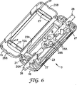
そして、ケーブルスプライスを用意し、上述したようにかつ図6に示すように、ケーブルを下部カバー部材3の上に配置する。図6は、図4の閉鎖容器が、2つのケーブル28の間の長手方向スプライスを保護するために使用されているプロセスを示す。ケーブルは、ワイヤ28Aの2つの対を備えるように示されており(ただしそれは必須ではない)、それらを、下部カバー部材3上に位置決めする。その際、一方のケーブルの個々のワイヤ28Aと他方のケーブルの個々のワイヤ28Aとの間の接続28Bを、キャビティ領域9内に配置し、ケーブル28が、歪み緩和構造21における開口25Aと壁19および23の凹所25Bとによって画定される経路に沿って、キャビティ領域9の反対側の端部から延在するようにする。そして、上述したようにスプライス閉鎖容器を閉鎖し、その結果、下部カバー部材3の仕切り23Aの上部が、上部カバー部材1の夫々の凹所15A内に位置する。同時に、キャビティ領域7の端部における二重壁17(間にシーラント材27がある)が、図5に示すようにキャビティ領域9の端部においてシーラント材27内にはまり込む。図5は、スプライス閉鎖容器の中心長手方向断面を示し、明確にするためにケーブルは省略している。その結果、スプライス閉鎖容器の内部キャビティの両端におけるシーラント材27が圧縮され、ケーブルおよびカバー部材の隣接面と有効に封止接触する。シーラント材はまた、その性質に応じて、格納空間からかつケーブルの外側に沿って限られた範囲で流れ出る傾向にある場合があり、それにより封止効果が向上する。このとき、ケーブルスプライスは、湿度に対してより高いレベルまで保護され、かつ上述したように機械的衝撃およびケーブル歪みに対して保護されるが、依然として、単に上部カバー部材を解除しそれを開位置まで移動させることにより容易にアクセス可能になる。
Then, a cable splice is prepared, and the cable is arranged on the
図4の閉鎖容器のためのシーラント材27を、キャビティ領域7、9の端部における格納空間に配置される予備形成されたゲルの形態で提供してもよい。別法として、シーラント材を液体の形態で提供してもよく、その場合、それを格納空間に注入し、そこで使用前にゲル状の粘稠度になるまで硬化させる。液体シーラント材が格納空間から隣接する凹所25A、25Bを通って溢れ出るいかなる傾向も、硬化時間の短い高粘度シーラント材を使用することにより制限することができる。
The
図7を参照すると、ケーブルスプライスが、湿度に対しより高いレベルの保護を必要とする場合、上述したようにスプライシングされたケーブルを下部カバー部材3上に配置する前に、キャビティ領域9の両側に沿った格納空間にもまた追加のシーラント材29を提供する。この場合、図4の仕切り23Aおよび関連する凹所15Aは不要であり、省略することができる。そして、上述したようにスプライス閉鎖容器を閉鎖し、これにより、図5および図8の断面図に示すように、キャビティ領域7の側壁15が二重端壁17(間にシーラント材27がある)とともに、キャビティ領域9の夫々両側および両端においてシーラント材29、27内にはまり込む。その結果、スプライス閉鎖容器の内部キャビティが、圧縮されたシーラント材によって包囲され、ケーブルスプライスは、さらに高レベルまで湿気に対して保護され(かつ、上述したように、機械的衝撃およびケーブル歪みに対して保護され)るが、依然として、単に上部カバー部材を解除し、それを開位置まで移動させることにより、容易にアクセス可能になる。
Referring to FIG. 7, if the cable splice requires a higher level of protection against humidity, before placing the spliced cable on the
上述したように、図7の閉鎖容器のためのシーラント材27、29を、キャビティ領域7の両端において、かつキャビティ領域9の両端および両側において、格納空間に配置される予備形成されたゲルの形態で提供してもよい。別法として、シーラント材を液体形態で提供してもよく、その場合、それを格納空間に注入し、そこで使用前にゲル状の粘稠度になるまで硬化させる。
As described above, the
上述したようにカバー部材1、3を備えるスプライス閉鎖容器の特定の利点は、単にカバー部材内の適当な位置にシーラント材を含めることにより、1つのタイプの閉鎖容器を使用して、湿気に対し複数のレベルの保護を提供することができる、ということである。実際に、図4に示すスプライス閉鎖容器を使用して、すべての場合に仕切り23Aが必要であるとは限らないという事実はあるが、図1、図4および図7に示す3つの異なるレベルの保護を提供することができる。各レベルの湿気保護に対し、スプライスに対する機械的衝撃およびケーブル歪みからの有効な保護も提供される。
A particular advantage of a splice enclosure with
スプライス閉鎖容器は、単純な構造であり、現場において困難な場所または手の届かない場所であっても容易に組み立てることができるように、使用する部品の数が比較的少ない。 Splice enclosures have a simple structure and use a relatively small number of parts so that they can be easily assembled even in difficult or unreachable sites.
保護のレベルを変えるために必要な変更(すなわち、シーラント材の追加)を、特に、液体シーラント材が使用される場合、製造業者または取付業者が容易に行うことができる。それは、特定の形状になるように予備形成されるゲルを取っておく必要がないためである。最大量のシーラント材(図7)は、絶対的に必要な場合にのみ使用する必要があり、それは、たとえばスプライスキャビティの全体がシーラント材で充填されている再入可能なスプライス閉鎖容器で使用される場合より依然として少ない。したがって、上述したようなカバー部材1、3を備えるスプライス閉鎖容器のコストを、スプライスキャビティの全体にシーラント材が充填されている場合のコストより低くすることができる。さらに、キャビティ領域7、9が空であるという事実により、より多くのスプライスを単一閉鎖容器内に収容することができ、スプライスを長期に配置するのにより優れた環境条件が提供され、閉鎖容器が再開放される場合のスプライスへのアクセスが容易になる。
Changes necessary to change the level of protection (ie addition of sealant material) can be easily made by the manufacturer or installer, especially when liquid sealant material is used. This is because it is not necessary to keep the gel preformed to a specific shape. The maximum amount of sealant material (Figure 7) should be used only when absolutely necessary, for example in reentrant splice enclosures where the entire splice cavity is filled with sealant material. Still less than if Therefore, the cost of the splice closure container including the
図面の図4および図7に示すスプライス閉鎖容器では1つのシーラント材しか使用しないため、異なるシーラント材間の中間面(たとえば、図7におけるシーラント材27、29の接合部分において、または上部カバー部材1および下部カバー部材3におけるシーラント材27間の接合部分において)に関連する封止問題がない。さらに、スプライス閉鎖容器の特定の構造(上述したように、閉鎖容器が閉鎖される時、上部カバー部材1における二重端壁17およびそこに収容されるシーラント材27が、下部カバー部材3のシーラント材27内にはまり込むようにする)により、ケーブル28が、閉鎖容器の中心キャビティ7、9のすぐ外側の領域でシーラント材27によって完全に包囲されることが確実になる。そのため、これらの位置におけるケーブルの周りの空隙、すなわち、上部カバー部材1のシーラント材27が下部カバー部材のシーラント材27と単に向い合せに接触する場合に発生する可能性があり、かつ存在する場合に中心キャビティ7、9に湿気を侵入させる可能性のある空隙の可能性がなくなる。
Since only one sealant material is used in the splice enclosure shown in FIGS. 4 and 7 of the drawings, an intermediate surface between different sealant materials (for example, at the joint portion of the
シーラント材27、29には、カバー部材1、3を閉鎖することによって圧縮されると、スプライス閉鎖容器が再開放されるまで有効な封止が維持されることを確実にするほど十分な、長期に亙る弾性があることが好ましい。シーラント材により、スプライス閉鎖容器が、後に再封止される(かつ必要な場合は、何回か開放され再び再封止される)ことが可能であり、ケーブルスプライスに対して同じレベルの保護を提供し続けることができる、ということが有利である。適当なシーラント材は、2004年2月2日に出願され「ミクロスフィア充填シーラント材(MICROSPHERE−FILLED SEALANT MATERIALS)」と題する本出願人による同時係属米国特許出願第10/770,095号明細書に記載されており、この出願の開示内容はすべて引用により本明細書に包含されたものとする。しかしながら、必要な場合、スプライス閉鎖容器が閉鎖された時にシーラント材に必要な圧縮力を加えるために、既知の方法でカバー部材1、3の適当な位置に1つまたは複数の外部弾性部材を位置決めすることができる。
The
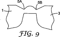
スプライス閉鎖容器の保護機能に影響を与えることなく、カバー部材1、3の構造に対してさまざまな変更を行うことができる、ということが理解されよう。一変更形態では、2つのカバー部材1、3間の単一ヒンジ5の代りに、図9に示すように2つのヒンジ5A、5Bを使用する。その変更により、各カバー部材を隣接するヒンジに対してわずかに90°移動させることによりスプライス閉鎖容器を閉鎖することができ、それにより各ヒンジに加わる歪みが低減する。図2に示すように単一ヒンジ5を採用する場合、ヒンジがカバー部材と一体成形されることは必須ではなく、別法として、たとえばインサート成形されるかまたは接着剤で取り付けられるフィルムまたはテープの形態での別個の部品であってもよい。カバー部材を合せて閉位置で保持するために使用されるラッチ11、12の形態、位置および数を変更することも可能である。
It will be appreciated that various changes can be made to the structure of the
スプライス閉鎖容器において歪み緩和構造21を提供することは、都合のよいことであるが、スプライス閉鎖容器を使用することができるケーブルのサイズを制限することになる。より径の大きいケーブルを使用するために、歪み緩和構造21を省略し、代りに従来のケーブルタイを使用することができる。別法として、歪み緩和構造21を、スプライス閉鎖容器で使用することが意図される最大径のケーブルを収容するように設計することができ、閉鎖容器をより径の小さいケーブルで使用することができるようにする何らかの追加の機構を提供することができる。図10は、たとえば、歪み緩和構造21の各々が5対ケーブルを収容するように設計されたスプライス閉鎖容器を示し、カバー部材3は、従来のケーブルタイを用いてより径の小さいケーブル(たとえば、2対ケーブル)を固定することができるコンパートメント30を提供するように、各端部において延長される。その目的のために、各コンパートメント30には、隣接する歪み緩和構造21のケーブル開口25Aと位置合せされ、かつスプライス閉鎖容器に入るケーブルに対する支持を提供するシート32が設けられる。ケーブルが歪み緩和構造21によって適当に固定されるには小さすぎる場合、ケーブルを、カバー部材3の開口34を通りケーブルおよびシートの周囲を通過するケーブルタイ(図示せず)によってシート32に固定することができる。
Providing the
この特許の教示により、当業者は、いかなるサイズのケーブルにまたはいかなる所望の数の対にも本発明を適用することができる。 The teachings of this patent allow one skilled in the art to apply the present invention to any size cable or to any desired number of pairs.
図10に示すスプライス閉鎖容器では、カバー部材1、3がケーブルスプライスを囲んで閉鎖される時に、シート32を収容するコンパートメント30が閉鎖されるように、カバー部材1もまたカバー部材3と同じ程度まで各端部において延長される。変更バージョンでは、ケーブルシート32を単にカバー部材の延長部として提供してもよく、それはスプライス閉鎖容器が閉鎖された時に露出したままであってもよい。
In the splice closure container shown in FIG. 10, the
図10はまた、カバー部材3に2つの脆弱部分36(コンパートメント30の各々の中に1つ)がある形態のスプライス閉鎖容器のさらなる変更も示す。脆弱部分36を、ねじで貫通することにより、必要な場合に閉鎖容器を平面に固定することができる。さらなる別法として、ねじの位置を、スプライス閉鎖容器が閉鎖された時にねじが露出しアクセス可能のままであるように、カバー部材3の延長部に設けてもよい。
FIG. 10 also shows a further modification of the splice closure container in which the
図10はさらに、キャビティ領域7、9の端部における格納空間の壁のケーブル開口/凹所25A、25Bが、スプライス閉鎖容器を使用する前に破壊可能な壁部26によってすべて閉鎖されることを示す。それら壁部26により、液体シーラント材が格納空間の壁の頂部のレベルまで注入され硬化中維持されることが可能となる。その後、壁部26は破壊可能であるため、関連する開口/凹所25A、25Bの適所にケーブルを置く動作によって除去され、それにより、ケーブルをシーラント材に有効に埋め込むことができる。同様に破壊可能な壁部を、図面を参照して上述した他のスプライス閉鎖容器のうちのいずれにおいても採用することができる。
FIG. 10 further shows that the cable openings / recesses 25A, 25B of the containment wall at the ends of the
図10はまた、歪み緩和構造21の各々の中央壁25のヒンジ5に隣接する部分に連続隆起部40を設けることも示す。連続隆起部40の各々は、カバー部材1のヒンジの反対側の夫々の開口41に係合可能であることにより、カバー部材1、3が閉鎖された時にヒンジに対する追加の保護を提供する。
FIG. 10 also shows that a
さらに、図面に示すものと全般的に同じタイプのスプライス閉鎖容器を使用して、いわゆる「ピッグテール」すなわちバットスプライス(すなわち、図6に示すような反対方向からではなく概して同じ方向から延在するケーブル間のスプライス)を保護することができる、ということが理解されよう。その場合、スプライス閉鎖容器(歪み緩和構造21を含む)には、ケーブルを、図面に示すように反対方向からではなく概して同じ方向から閉鎖容器に差し込むことができるようにする変更が必要である。 Furthermore, using a splice closure generally of the same type as shown in the drawings, a so-called “pigtail” or butt splice (ie, a cable extending generally from the same direction rather than from the opposite direction as shown in FIG. 6). It will be understood that the splice between) can be protected. In that case, the splice enclosure (including the strain relief structure 21) requires a modification that allows the cable to be plugged into the enclosure from generally the same direction, as shown in the drawing, rather than from the opposite direction.
図面を参照して上述したスプライス閉鎖容器のうちの任意のもののケーブル差込経路をさらに変更することにより、異なる数のケーブル間のスプライス、たとえば、一方の方向から延在する1つのケーブルと他方の方向から延在する2つのケーブルとの間の長手方向スプライスに対し保護を提供することができる。 By further changing the cable insertion path of any of the splice enclosures described above with reference to the drawings, splices between different numbers of cables, eg, one cable extending from one direction and the other Protection can be provided against a longitudinal splice between two cables extending from the direction.
Claims (3)
第1および第2カバー部材(1、3)であって、それらの内壁(17、23、25)が、該カバー部材(1、3)が閉位置において互いに係合すると該ケーブルスプライスを封入するキャビティ(7、9)を形成するように構成される、第1および第2カバー部材(1、3)を具備し、
(i)両カバー部材(1、3)の該内壁(17、23、25)はさらに、少なくとも部分的に該キャビティ(7、9)を包囲する、シーラント材(27)を収納した格納空間(17A)を確定するように構成され、
(ii)該カバー部材(1、3)が該閉位置において互いに係合すると、一方のカバー部材(1、3)の格納空間(17A)が、他方のカバー部材の格納空間(17A)内にはまり込み、それによりそこに収容されたシーラント材(27)を圧縮し、
(iii)前記シーラント材(27)が圧縮可能なミクロスフィア充填シーラント材であり、
(iv)前記ケーブルスプライスを封入するキャビティ(7、9)にはシーラント材が充填されていない、閉鎖容器。A reentrant enclosure for the splice between cables,
First and second cover members (1, 3) whose inner walls (17, 23, 25) enclose the cable splice when the cover members (1, 3) engage each other in the closed position Comprising first and second cover members (1, 3) configured to form cavities (7, 9);
(I) The inner walls (17, 23, 25) of both cover members (1, 3) further contain storage space (27) containing a sealant material (27) that at least partially surrounds the cavity (7, 9). 17A) is established,
(Ii) When the cover members (1, 3) are engaged with each other in the closed position, the storage space (17A) of one cover member (1, 3) is in the storage space (17A) of the other cover member. Inset, thereby compressing the sealant material (27) contained therein,
(Iii) Ri said sealant material (27) is compressible microspheres filled sealant material der,
(Iv) A closed container in which the cavities (7, 9) enclosing the cable splice are not filled with a sealant material .
Applications Claiming Priority (3)
| Application Number | Priority Date | Filing Date | Title |
|---|---|---|---|
| US10/770,377 US7141738B2 (en) | 2004-02-02 | 2004-02-02 | Re-enterable splice enclosure |
| US10/770,377 | 2004-02-02 | ||
| PCT/US2005/000107 WO2005076427A1 (en) | 2004-02-02 | 2005-01-04 | Re-enterable splice enclosure |
Publications (3)
| Publication Number | Publication Date |
|---|---|
| JP2007520990A JP2007520990A (en) | 2007-07-26 |
| JP2007520990A5 JP2007520990A5 (en) | 2008-02-14 |
| JP4749342B2 true JP4749342B2 (en) | 2011-08-17 |
Family
ID=34808317
Family Applications (1)
| Application Number | Title | Priority Date | Filing Date |
|---|---|---|---|
| JP2006552116A Active JP4749342B2 (en) | 2004-02-02 | 2005-01-04 | Re-entrant splice closure |
Country Status (16)
| Country | Link |
|---|---|
| US (1) | US7141738B2 (en) |
| EP (1) | EP1711989B1 (en) |
| JP (1) | JP4749342B2 (en) |
| CN (1) | CN100555783C (en) |
| AT (1) | ATE395739T1 (en) |
| AU (1) | AU2005211099A1 (en) |
| BR (1) | BRPI0507368B1 (en) |
| CA (1) | CA2554960A1 (en) |
| DE (1) | DE602005006741D1 (en) |
| DK (1) | DK1711989T3 (en) |
| EG (1) | EG24471A (en) |
| MY (1) | MY139820A (en) |
| NO (1) | NO20063625L (en) |
| RU (1) | RU2361347C2 (en) |
| TW (1) | TW200537778A (en) |
| WO (1) | WO2005076427A1 (en) |
Families Citing this family (65)
| Publication number | Priority date | Publication date | Assignee | Title |
|---|---|---|---|---|
| US7141738B2 (en) * | 2004-02-02 | 2006-11-28 | 3M Innovative Properties Company | Re-enterable splice enclosure |
| US7273984B2 (en) * | 2005-07-11 | 2007-09-25 | Twins Investments Company | Outdoor cord connection cover apparatus |
| CN101170247B (en) * | 2006-10-27 | 2010-05-19 | 3M新设资产公司 | Re-accessible connector enclosing cover |
| US7618269B2 (en) * | 2007-02-28 | 2009-11-17 | Hubbell Incorporated | Compliant cap |
| US7453042B2 (en) * | 2007-04-09 | 2008-11-18 | Andrew Llc | Cable and apparatus interconnection close quarters environmental seal |
| JP2009020221A (en) * | 2007-07-11 | 2009-01-29 | Fujikura Ltd | Optical closure and method of optical wiring from optical cable assembly to subscriber's house |
| US7562864B2 (en) * | 2007-10-09 | 2009-07-21 | Robbins Iii Edward S | Fence splice cover assembly |
| US7885505B2 (en) | 2007-10-22 | 2011-02-08 | Adc Telecommunications, Inc. | Wavelength division multiplexing module |
| US7536075B2 (en) * | 2007-10-22 | 2009-05-19 | Adc Telecommunications, Inc. | Wavelength division multiplexing module |
| FR2926166B1 (en) * | 2008-01-08 | 2010-06-11 | Ge Energy Products France Snc | KIT OF TEMPERATURE SENSORS, IN PARTICULAR FOR COMBUSTION TURBINE. |
| US7697812B2 (en) * | 2008-01-18 | 2010-04-13 | 3M Innovative Properties Company | Enclosure and organizer for telecommunication lines and splices |
| US8107816B2 (en) | 2008-01-29 | 2012-01-31 | Adc Telecommunications, Inc. | Wavelength division multiplexing module |
| DE102008051482A1 (en) * | 2008-04-01 | 2009-10-08 | Zumtobel Lighting Gmbh | Strain relief device |
| SE0850021L (en) * | 2008-09-23 | 2009-12-29 | Syntune Ab | Waveguide for low reflex switch-off. |
| ES2380503T3 (en) * | 2008-10-30 | 2012-05-14 | 3M Innovative Properties Company | Waterproof case |
| US8084691B2 (en) * | 2008-11-18 | 2011-12-27 | Tyco Electronics Corporation | Sealant-filled enclosures and methods for environmentally protecting a connection |
| CA2988835C (en) * | 2008-11-18 | 2020-01-21 | Tyco Electronics Corporation | Sealant-filled enclosures and methods for environmentally protecting a connection |
| TWI420768B (en) * | 2009-02-26 | 2013-12-21 | Chi Yu Fen | Communication cable connection box with flexible rubber shrink tube waterproof device |
| CA2792885C (en) * | 2010-03-29 | 2016-05-17 | Afl Telecommunications Llc | High fiber count package inner module |
| CN102221735B (en) * | 2010-04-16 | 2013-07-17 | 泰科电子(上海)有限公司 | Cable connector box |
| DE202010006582U1 (en) * | 2010-05-07 | 2010-08-05 | CCS Technology, Inc., Wilmington | Inline cable sleeve |
| US9012774B2 (en) * | 2010-06-21 | 2015-04-21 | 3M Innovative Properties Company | Sealing member for an enclosure |
| CN102331609B (en) * | 2010-07-13 | 2015-05-27 | 泰科电子(上海)有限公司 | Optical fiber terminal box |
| CN201789149U (en) * | 2010-08-10 | 2011-04-06 | 泰科电子(上海)有限公司 | Sealing device for sealing connecting piece |
| CN201829633U (en) * | 2010-08-18 | 2011-05-11 | 泰科电子(上海)有限公司 | Sealed junction box |
| ES2516191T3 (en) | 2010-10-19 | 2014-10-30 | 3M Innovative Properties Company | Housing for a cable connection |
| US9502873B2 (en) | 2010-11-10 | 2016-11-22 | Emerson Climate Technologies, Inc. | Compressor and enclosure assembly for electrical components |
| US8476540B2 (en) | 2010-12-14 | 2013-07-02 | Trystar, Inc. | Shelter for portable electrical inlets/outlets |
| US9476251B2 (en) * | 2011-08-19 | 2016-10-25 | Aerovironment, Inc. | Water-tight compartment with removable hatch and two-sided gel seal for multiple conduit access |
| US8960973B1 (en) * | 2011-10-06 | 2015-02-24 | Cooper Technologies Company | Splice enclosure for luminaires |
| US9480177B2 (en) | 2012-07-27 | 2016-10-25 | Emerson Climate Technologies, Inc. | Compressor protection module |
| WO2014035611A1 (en) * | 2012-08-30 | 2014-03-06 | 3M Innovative Properties Company | Sealed fiber optic splice tray |
| US9326391B2 (en) | 2012-08-31 | 2016-04-26 | Apple Inc. | Combined audio jack and mobile electronic device enclosure |
| EP2994966A1 (en) | 2013-05-09 | 2016-03-16 | Tyco Electronics Raychem BVBA | Sealing block with stackable sealing element |
| US11098502B2 (en) * | 2014-05-15 | 2021-08-24 | Steven Joseph Jaworski | Tamper proof cable lock |
| WO2015200321A1 (en) | 2014-06-23 | 2015-12-30 | Adc Telecommunications, Inc. | Fiber cable fan-out assembly and method |
| US9363343B2 (en) * | 2014-08-29 | 2016-06-07 | Apple Inc. | Audio jack connector integrated into enclosure |
| ES1132305Y (en) * | 2014-10-22 | 2015-01-28 | Simon S A U | Quick flanging device for electrical connections |
| US10054753B2 (en) | 2014-10-27 | 2018-08-21 | Commscope Technologies Llc | Fiber optic cable with flexible conduit |
| AT517416B1 (en) * | 2015-05-06 | 2017-06-15 | Gebauer & Griller Kabelwerke Ges M B H | CABLE AND METHOD FOR PRODUCING A CABLE |
| AU2015207954C1 (en) | 2015-07-31 | 2022-05-05 | Adc Communications (Australia) Pty Limited | Cable breakout assembly |
| JP6342859B2 (en) * | 2015-08-18 | 2018-06-13 | 矢崎総業株式会社 | Optical connector |
| US11131821B2 (en) | 2016-03-18 | 2021-09-28 | Commscope Technologies Llc | Optic fiber cable fanout conduit arrangements; components, and methods |
| WO2018044729A1 (en) | 2016-08-31 | 2018-03-08 | Commscope Technologies Llc | Fiber optic cable clamp and clamp assembly |
| EP3526633A4 (en) | 2016-10-13 | 2020-05-20 | Commscope Technologies LLC | Fiber optic breakout transition assembly incorporating epoxy plug and cable strain relief |
| JP6466983B2 (en) | 2017-03-22 | 2019-02-06 | 京セラ株式会社 | connector |
| USD960114S1 (en) * | 2017-04-20 | 2022-08-09 | University Of Tennessee Research Foundation | Tampering detection enclosure |
| USD960115S1 (en) * | 2017-04-20 | 2022-08-09 | University Of Tennessee Research Foundation | Tampering detection enclosure |
| USD826874S1 (en) * | 2017-04-20 | 2018-08-28 | University Of Tennessee Research Foundation | Tampering detection clamping box for ingress and egress lines |
| WO2018208518A1 (en) | 2017-05-08 | 2018-11-15 | Commscope Technologies Llc | Fiber-optic breakout transition assembly |
| USD848992S1 (en) * | 2017-05-26 | 2019-05-21 | Samsung Electronics Co., Ltd. | Connecting device for wireless communications |
| US10283954B2 (en) * | 2017-07-28 | 2019-05-07 | Nicholas T. Tavare | Connection shield for power distribution networks |
| WO2019190760A1 (en) | 2018-03-29 | 2019-10-03 | Corning Research & Development Corporation | Pre-mold assembly for branched optical cable and related method |
| EP3791220B1 (en) | 2018-05-09 | 2023-07-05 | AFL Telecommunications LLC | Butt closures and bases therefor |
| IT201800005665A1 (en) * | 2018-05-24 | 2019-11-24 | CONNECTION BOX, IN PARTICULAR FOR THE SEALING AND INSULATION OF ELECTRICAL AND SIMILAR CONNECTIONS | |
| CN109217227A (en) * | 2018-08-15 | 2019-01-15 | 深圳供电局有限公司 | Screw rod reinforced high-voltage cable intermediate joint protective shell |
| CN108879578A (en) * | 2018-08-16 | 2018-11-23 | 深圳供电局有限公司 | Stackable cable intermediate joint protective shell |
| US20220131355A1 (en) * | 2019-03-13 | 2022-04-28 | Commscope Technologies Llc | Re-enterable enclosure with environmental sealing |
| JP7272032B2 (en) * | 2019-03-20 | 2023-05-12 | 住友電装株式会社 | connector |
| EP3981052A4 (en) * | 2019-06-05 | 2023-10-11 | Tyco Fire Products LP | Clamping connector |
| US11515696B2 (en) * | 2019-12-17 | 2022-11-29 | Te Connectivity Solutions Gmbh | Electrical component enclosure with injected seal and method |
| US10996414B1 (en) | 2020-03-23 | 2021-05-04 | Afl Telecommunications Llc | Butt closures and bases therefor |
| US11657929B2 (en) * | 2020-04-02 | 2023-05-23 | Commscope Technologies Llc | Cable cuffs for multiple sized cables |
| US12078846B2 (en) | 2020-11-30 | 2024-09-03 | Afl Telecommunications Llc | Butt closures and bases therefor |
| CN113451804A (en) * | 2021-06-30 | 2021-09-28 | 贵州电网有限责任公司 | High-reliability multifunctional interface suitable for 500kV relay protection |
Citations (4)
| Publication number | Priority date | Publication date | Assignee | Title |
|---|---|---|---|---|
| JPH1141781A (en) * | 1997-07-22 | 1999-02-12 | Harness Sogo Gijutsu Kenkyusho:Kk | Waterproof case at wire joint |
| JPH11204982A (en) * | 1998-01-08 | 1999-07-30 | Takeuchi Kogyo Kk | Noise absorber |
| JP2002056906A (en) * | 2000-08-11 | 2002-02-22 | Nichifu Co Ltd | Waterproof cover for connector |
| JP2002543753A (en) * | 1999-04-29 | 2002-12-17 | スリーエム イノベイティブ プロパティズ カンパニー | Low voltage reentrant splice enclosure |
Family Cites Families (38)
| Publication number | Priority date | Publication date | Assignee | Title |
|---|---|---|---|---|
| US3183302A (en) * | 1962-01-08 | 1965-05-11 | Jasper Blackburn Corp | Cover for an electrical connector |
| US4449015A (en) * | 1981-05-18 | 1984-05-15 | Proto Production Plastics, Inc. | Connector cover with multiple mounting means |
| US4423918A (en) | 1981-08-18 | 1984-01-03 | Minnesota Mining & Manufacturing Company | Re-enterable service wire splice closure |
| US4451696A (en) * | 1982-11-15 | 1984-05-29 | Amp Incorporated | Toolless splice sealant device |
| AU5314386A (en) * | 1985-01-04 | 1986-07-29 | Raychem Corporation | Splice case |
| US4610738A (en) * | 1985-01-04 | 1986-09-09 | Raychem Corporation | Encapsulating a splice with a gel-filled case |
| DE233417T1 (en) | 1986-02-21 | 1988-01-14 | Etablissements Morel - Ateliers Electromecaniques De Favieres, Chateauneuf-En-Thymerais, Eure-Et-Loir | PLASTIC MATERIAL SLEEVE TO PROTECT A SPLICE OF ELECTRICAL CABLES OR MESSAGE CABLES, AND METHOD FOR PRODUCING THE SEAL OF SUCH A SLEEVE. |
| JP2510577B2 (en) | 1987-05-13 | 1996-06-26 | 東芝シリコ−ン株式会社 | Curable silicone gel composition |
| US4849580A (en) | 1988-02-11 | 1989-07-18 | Minnesota Mining And Manufacturing Company | Environmental protection closure for wire splices; and method |
| US4879436A (en) * | 1988-08-18 | 1989-11-07 | Northern Telecom Limited | Closure for telecommunications cable |
| AR247957A1 (en) | 1988-11-09 | 1995-04-28 | Raychem Sa Nv | Closure assembly |
| WO1990010035A1 (en) * | 1989-03-01 | 1990-09-07 | Raychem Corporation | Method of curing organopolysiloxane compositions and compositions and articles therefrom |
| JPH0353466A (en) * | 1989-07-19 | 1991-03-07 | Three Bond Co Ltd | Coating member for joint member |
| GB9112181D0 (en) | 1991-06-06 | 1991-07-24 | Raychem Sa Nv | Cable sealing |
| WO1992022116A1 (en) | 1991-06-07 | 1992-12-10 | Raychem Corporation | Hinged gel-filled security and environmental protection device |
| US5310075A (en) * | 1992-11-27 | 1994-05-10 | Distribution Control Systems, Inc. | Waterproof, gasketless enclosure |
| DE69413050T2 (en) | 1993-10-07 | 1999-01-21 | N.V. Raychem S.A., Kessel-Lo, Leuven | ENVIRONMENTAL PROTECTION DEVICE |
| GB9322929D0 (en) | 1993-11-08 | 1994-01-05 | Raychem Sa Nv | Cable closure |
| MY112885A (en) | 1993-12-01 | 2001-10-31 | N V Raychem S A | Sealing device. |
| US5397859A (en) * | 1993-12-10 | 1995-03-14 | The Whitaker Corporation | Enclosure with sealant for spliced coaxial cables |
| AU1276195A (en) | 1993-12-22 | 1995-07-10 | Raychem Limited | Cable joint |
| GB9403838D0 (en) | 1994-02-28 | 1994-04-20 | Raychem Sa Nv | Environmental sealing |
| JPH07245030A (en) * | 1994-03-07 | 1995-09-19 | Sumitomo Wiring Syst Ltd | Grommet |
| US5529508A (en) * | 1994-04-01 | 1996-06-25 | Raychem Corporation | Sealing member |
| US5525073A (en) | 1994-06-01 | 1996-06-11 | Raychem Corporation | Environmental protection device with manually operated latch mechanism |
| US5777268A (en) | 1995-10-06 | 1998-07-07 | Raychem Corporation | Splice closure for buried telecommunications cables |
| GB9505458D0 (en) | 1995-03-17 | 1995-05-03 | Raychem Ltd | An article for protecting a multi-conductor connector |
| DE59500604D1 (en) | 1995-03-22 | 1997-10-09 | Sonderhoff Ernst Fa | Process for producing a foamed or non-foamed soft-elastic silicone elastomer, in particular for sealing purposes |
| US5763835A (en) * | 1995-11-01 | 1998-06-09 | Raychem Corporation | Gel-filled closure |
| ID15837A (en) | 1996-01-24 | 1997-08-14 | Raychem Sa Nv | CABLE COVER |
| US5844171A (en) * | 1997-04-22 | 1998-12-01 | Mev Corporation | Environmentally enclosed cable splice |
| FR2770048B1 (en) | 1997-10-16 | 1999-12-31 | Rxs Morel Accessoires De Cable | SPLICE PROTECTION DEVICE AND METHOD FOR ALLOWING THE PLACEMENT OF SUCH A DEVICE |
| GB9815080D0 (en) | 1998-07-10 | 1998-09-09 | Dow Corning Sa | Compressible silicone composition |
| FR2789816B1 (en) | 1999-02-17 | 2001-03-30 | Rxs Morel Accessoires De Cable | SPLICE PROTECTION DEVICE |
| FR2820555B1 (en) | 2001-02-06 | 2003-04-11 | 3M Innovative Properties Co | WATERPROOF AND MODULAR CABLE PASSAGE WITH EASY CABLE POSITIONING AND SLEEVE EQUIPPED WITH SUCH A PASSAGE |
| JP2002294076A (en) * | 2001-04-02 | 2002-10-09 | Dow Corning Toray Silicone Co Ltd | Silicone gel composition for molding in metal mold |
| CN1269260C (en) * | 2002-10-18 | 2006-08-09 | 矢崎总业株式会社 | Sealing-up structure of insulate line |
| US7141738B2 (en) * | 2004-02-02 | 2006-11-28 | 3M Innovative Properties Company | Re-enterable splice enclosure |
-
2004
- 2004-02-02 US US10/770,377 patent/US7141738B2/en not_active Expired - Lifetime
-
2005
- 2005-01-04 CA CA002554960A patent/CA2554960A1/en not_active Abandoned
- 2005-01-04 AU AU2005211099A patent/AU2005211099A1/en not_active Abandoned
- 2005-01-04 JP JP2006552116A patent/JP4749342B2/en active Active
- 2005-01-04 EP EP05704941A patent/EP1711989B1/en active Active
- 2005-01-04 DK DK05704941T patent/DK1711989T3/en active
- 2005-01-04 BR BRPI0507368-5A patent/BRPI0507368B1/en active IP Right Grant
- 2005-01-04 AT AT05704941T patent/ATE395739T1/en not_active IP Right Cessation
- 2005-01-04 DE DE602005006741T patent/DE602005006741D1/en not_active Expired - Fee Related
- 2005-01-04 WO PCT/US2005/000107 patent/WO2005076427A1/en active Application Filing
- 2005-01-04 RU RU2006128074/09A patent/RU2361347C2/en active
- 2005-01-04 CN CNB2005800065645A patent/CN100555783C/en active Active
- 2005-01-18 TW TW094101436A patent/TW200537778A/en unknown
- 2005-01-29 MY MYPI20050368A patent/MY139820A/en unknown
-
2006
- 2006-08-10 NO NO20063625A patent/NO20063625L/en not_active Application Discontinuation
-
2008
- 2008-08-02 EG EGNA2006000731 patent/EG24471A/en active
Patent Citations (4)
| Publication number | Priority date | Publication date | Assignee | Title |
|---|---|---|---|---|
| JPH1141781A (en) * | 1997-07-22 | 1999-02-12 | Harness Sogo Gijutsu Kenkyusho:Kk | Waterproof case at wire joint |
| JPH11204982A (en) * | 1998-01-08 | 1999-07-30 | Takeuchi Kogyo Kk | Noise absorber |
| JP2002543753A (en) * | 1999-04-29 | 2002-12-17 | スリーエム イノベイティブ プロパティズ カンパニー | Low voltage reentrant splice enclosure |
| JP2002056906A (en) * | 2000-08-11 | 2002-02-22 | Nichifu Co Ltd | Waterproof cover for connector |
Also Published As
| Publication number | Publication date |
|---|---|
| MY139820A (en) | 2009-10-30 |
| RU2361347C2 (en) | 2009-07-10 |
| AU2005211099A1 (en) | 2005-08-18 |
| RU2006128074A (en) | 2008-03-10 |
| BRPI0507368B1 (en) | 2018-07-24 |
| DE602005006741D1 (en) | 2008-06-26 |
| DK1711989T3 (en) | 2008-09-01 |
| CN100555783C (en) | 2009-10-28 |
| WO2005076427A1 (en) | 2005-08-18 |
| EP1711989A1 (en) | 2006-10-18 |
| EG24471A (en) | 2009-08-03 |
| TW200537778A (en) | 2005-11-16 |
| NO20063625L (en) | 2006-11-01 |
| US20050167147A1 (en) | 2005-08-04 |
| CN1926738A (en) | 2007-03-07 |
| ATE395739T1 (en) | 2008-05-15 |
| US7141738B2 (en) | 2006-11-28 |
| CA2554960A1 (en) | 2005-08-18 |
| EP1711989B1 (en) | 2008-05-14 |
| JP2007520990A (en) | 2007-07-26 |
| BRPI0507368A (en) | 2007-07-10 |
Similar Documents
| Publication | Publication Date | Title |
|---|---|---|
| JP4749342B2 (en) | Re-entrant splice closure | |
| KR20090074782A (en) | Re-enterable splice enclosure | |
| US5862290A (en) | Optical fiber cable splice closure | |
| US4435612A (en) | Cable splice housing | |
| US5907653A (en) | Racetrack grommet for optical fiber cable splice closure | |
| RU2181496C2 (en) | Closing of optical fiber splicing | |
| US5896486A (en) | Mass splice tray for optical fibers | |
| JP2007520990A5 (en) | ||
| KR950001441A (en) | Optical waveguide module | |
| US20100316347A1 (en) | Cable pulling assembly | |
| KR20110116048A (en) | Housing for an optical fibre assembly | |
| US5111001A (en) | Splice case | |
| KR0170765B1 (en) | Method for encapsulating an optical component and the encapsulated component obtained thereby | |
| KR20070017121A (en) | Re-enterable splice enclosure | |
| JPS59135414A (en) | Package apparatus for optical fiber connector and manufacture thereof | |
| EP2557442B1 (en) | Cable closure | |
| GB2151041A (en) | Optical cable joint | |
| MXPA06008744A (en) | Re-enterable splice enclosure | |
| JP2005010508A (en) | Optical waveguide package | |
| JPH0322722Y2 (en) | ||
| JP2002222713A (en) | Hinge structure | |
| JPH10307214A (en) | Coupler storage tray | |
| CZ15856U1 (en) | Cable coupling | |
| EP0621989A4 (en) | Splice case. | |
| RU99116602A (en) | DEVICE FOR CONNECTING FIBER OPTICAL CABLES |
Legal Events
| Date | Code | Title | Description |
|---|---|---|---|
| A521 | Request for written amendment filed |
Free format text: JAPANESE INTERMEDIATE CODE: A523 Effective date: 20071218 |
|
| A621 | Written request for application examination |
Free format text: JAPANESE INTERMEDIATE CODE: A621 Effective date: 20071218 |
|
| A131 | Notification of reasons for refusal |
Free format text: JAPANESE INTERMEDIATE CODE: A131 Effective date: 20090414 |
|
| A601 | Written request for extension of time |
Free format text: JAPANESE INTERMEDIATE CODE: A601 Effective date: 20090714 |
|
| A602 | Written permission of extension of time |
Free format text: JAPANESE INTERMEDIATE CODE: A602 Effective date: 20090722 |
|
| A521 | Request for written amendment filed |
Free format text: JAPANESE INTERMEDIATE CODE: A523 Effective date: 20090804 |
|
| RD03 | Notification of appointment of power of attorney |
Free format text: JAPANESE INTERMEDIATE CODE: A7423 Effective date: 20090804 |
|
| RD04 | Notification of resignation of power of attorney |
Free format text: JAPANESE INTERMEDIATE CODE: A7424 Effective date: 20091228 |
|
| A131 | Notification of reasons for refusal |
Free format text: JAPANESE INTERMEDIATE CODE: A131 Effective date: 20100216 |
|
| A521 | Request for written amendment filed |
Free format text: JAPANESE INTERMEDIATE CODE: A523 Effective date: 20100514 |
|
| A02 | Decision of refusal |
Free format text: JAPANESE INTERMEDIATE CODE: A02 Effective date: 20101124 |
|
| A521 | Request for written amendment filed |
Free format text: JAPANESE INTERMEDIATE CODE: A523 Effective date: 20110324 |
|
| A911 | Transfer to examiner for re-examination before appeal (zenchi) |
Free format text: JAPANESE INTERMEDIATE CODE: A911 Effective date: 20110329 |
|
| TRDD | Decision of grant or rejection written | ||
| A01 | Written decision to grant a patent or to grant a registration (utility model) |
Free format text: JAPANESE INTERMEDIATE CODE: A01 Effective date: 20110426 |
|
| A61 | First payment of annual fees (during grant procedure) |
Free format text: JAPANESE INTERMEDIATE CODE: A61 Effective date: 20110517 |
|
| R150 | Certificate of patent or registration of utility model |
Free format text: JAPANESE INTERMEDIATE CODE: R150 Ref document number: 4749342 Country of ref document: JP Free format text: JAPANESE INTERMEDIATE CODE: R150 |
|
| FPAY | Renewal fee payment (event date is renewal date of database) |
Free format text: PAYMENT UNTIL: 20140527 Year of fee payment: 3 |
|
| R250 | Receipt of annual fees |
Free format text: JAPANESE INTERMEDIATE CODE: R250 |
|
| R250 | Receipt of annual fees |
Free format text: JAPANESE INTERMEDIATE CODE: R250 |
|
| R250 | Receipt of annual fees |
Free format text: JAPANESE INTERMEDIATE CODE: R250 |
|
| R250 | Receipt of annual fees |
Free format text: JAPANESE INTERMEDIATE CODE: R250 |
|
| R250 | Receipt of annual fees |
Free format text: JAPANESE INTERMEDIATE CODE: R250 |
|
| S111 | Request for change of ownership or part of ownership |
Free format text: JAPANESE INTERMEDIATE CODE: R313113 |
|
| R360 | Written notification for declining of transfer of rights |
Free format text: JAPANESE INTERMEDIATE CODE: R360 |
|
| R360 | Written notification for declining of transfer of rights |
Free format text: JAPANESE INTERMEDIATE CODE: R360 |
|
| R371 | Transfer withdrawn |
Free format text: JAPANESE INTERMEDIATE CODE: R371 |
|
| S111 | Request for change of ownership or part of ownership |
Free format text: JAPANESE INTERMEDIATE CODE: R313113 |
|
| R250 | Receipt of annual fees |
Free format text: JAPANESE INTERMEDIATE CODE: R250 |
|
| R371 | Transfer withdrawn |
Free format text: JAPANESE INTERMEDIATE CODE: R371 |
|
| S111 | Request for change of ownership or part of ownership |
Free format text: JAPANESE INTERMEDIATE CODE: R313113 |
|
| R350 | Written notification of registration of transfer |
Free format text: JAPANESE INTERMEDIATE CODE: R350 |
|
| R250 | Receipt of annual fees |
Free format text: JAPANESE INTERMEDIATE CODE: R250 |
|
| R250 | Receipt of annual fees |
Free format text: JAPANESE INTERMEDIATE CODE: R250 |
|
| R250 | Receipt of annual fees |
Free format text: JAPANESE INTERMEDIATE CODE: R250 |
|
| R250 | Receipt of annual fees |
Free format text: JAPANESE INTERMEDIATE CODE: R250 |
|
| R250 | Receipt of annual fees |
Free format text: JAPANESE INTERMEDIATE CODE: R250 |