EP1711989B1 - Re-enterable splice enclosure - Google Patents
Re-enterable splice enclosure Download PDFInfo
- Publication number
- EP1711989B1 EP1711989B1 EP05704941A EP05704941A EP1711989B1 EP 1711989 B1 EP1711989 B1 EP 1711989B1 EP 05704941 A EP05704941 A EP 05704941A EP 05704941 A EP05704941 A EP 05704941A EP 1711989 B1 EP1711989 B1 EP 1711989B1
- Authority
- EP
- European Patent Office
- Prior art keywords
- splice
- enclosure
- sealant material
- cover members
- cavity
- Prior art date
- Legal status (The legal status is an assumption and is not a legal conclusion. Google has not performed a legal analysis and makes no representation as to the accuracy of the status listed.)
- Active
Links
- 239000012812 sealant material Substances 0.000 claims abstract description 59
- 230000004048 modification Effects 0.000 description 7
- 238000012986 modification Methods 0.000 description 7
- 230000004888 barrier function Effects 0.000 description 5
- 239000007788 liquid Substances 0.000 description 5
- 238000007789 sealing Methods 0.000 description 4
- 238000010276 construction Methods 0.000 description 3
- 230000000694 effects Effects 0.000 description 3
- 230000008901 benefit Effects 0.000 description 2
- 230000007774 longterm Effects 0.000 description 2
- 230000000717 retained effect Effects 0.000 description 2
- 239000004952 Polyamide Substances 0.000 description 1
- 239000004743 Polypropylene Substances 0.000 description 1
- 230000009471 action Effects 0.000 description 1
- 239000000853 adhesive Substances 0.000 description 1
- 230000001070 adhesive effect Effects 0.000 description 1
- 238000005452 bending Methods 0.000 description 1
- 230000008859 change Effects 0.000 description 1
- 230000001419 dependent effect Effects 0.000 description 1
- 230000002708 enhancing effect Effects 0.000 description 1
- 230000007613 environmental effect Effects 0.000 description 1
- 239000000463 material Substances 0.000 description 1
- 230000007246 mechanism Effects 0.000 description 1
- 238000000034 method Methods 0.000 description 1
- 238000000465 moulding Methods 0.000 description 1
- 239000013307 optical fiber Substances 0.000 description 1
- 239000004033 plastic Substances 0.000 description 1
- 229920003023 plastic Polymers 0.000 description 1
- 229920002647 polyamide Polymers 0.000 description 1
- -1 polypropylene Polymers 0.000 description 1
- 229920001155 polypropylene Polymers 0.000 description 1
- 230000008569 process Effects 0.000 description 1
- 230000001681 protective effect Effects 0.000 description 1
- 230000009993 protective function Effects 0.000 description 1
- 239000003566 sealing material Substances 0.000 description 1
Images


Classifications
-
- G—PHYSICS
- G02—OPTICS
- G02B—OPTICAL ELEMENTS, SYSTEMS OR APPARATUS
- G02B6/00—Light guides; Structural details of arrangements comprising light guides and other optical elements, e.g. couplings
- G02B6/44—Mechanical structures for providing tensile strength and external protection for fibres, e.g. optical transmission cables
- G02B6/4439—Auxiliary devices
- G02B6/444—Systems or boxes with surplus lengths
- G02B6/4441—Boxes
- G02B6/4446—Cable boxes, e.g. splicing boxes with two or more multi fibre cables
-
- H—ELECTRICITY
- H02—GENERATION; CONVERSION OR DISTRIBUTION OF ELECTRIC POWER
- H02G—INSTALLATION OF ELECTRIC CABLES OR LINES, OR OF COMBINED OPTICAL AND ELECTRIC CABLES OR LINES
- H02G15/00—Cable fittings
- H02G15/013—Sealing means for cable inlets
-
- G—PHYSICS
- G02—OPTICS
- G02B—OPTICAL ELEMENTS, SYSTEMS OR APPARATUS
- G02B6/00—Light guides; Structural details of arrangements comprising light guides and other optical elements, e.g. couplings
- G02B6/44—Mechanical structures for providing tensile strength and external protection for fibres, e.g. optical transmission cables
- G02B6/4439—Auxiliary devices
- G02B6/444—Systems or boxes with surplus lengths
- G02B6/4441—Boxes
- G02B6/4446—Cable boxes, e.g. splicing boxes with two or more multi fibre cables
- G02B6/44465—Seals
-
- H—ELECTRICITY
- H02—GENERATION; CONVERSION OR DISTRIBUTION OF ELECTRIC POWER
- H02G—INSTALLATION OF ELECTRIC CABLES OR LINES, OR OF COMBINED OPTICAL AND ELECTRIC CABLES OR LINES
- H02G15/00—Cable fittings
- H02G15/08—Cable junctions
- H02G15/10—Cable junctions protected by boxes, e.g. by distribution, connection or junction boxes
- H02G15/113—Boxes split longitudinally in main cable direction
Definitions
- the present invention relates to an enclosure for a splice between cables, the enclosure being of the type that can be re-opened, re-enterable, to permit access to the cable splice when required and, preferably, then re-sealed.
- the cable may, for example, be a telecommunications cable, a power cable or an optical fibre cable.
- the cable splice may, for example, be a longitudinally-extending splice (i.e. a splice between cables that extend generally from opposite directions) or a so-called “pigtail", or butt, splice (i.e. a splice between cables that extend generally from the same direction).
- a cable splice will generally require protection from the effects of the environment in which it is located and, more especially, will require protection against mechanical impact and the entry of moisture. Protection of the cables against strain will often also be required. Many different enclosures providing different levels of protection for cable splices are already available, including so-called re-enterable enclosures that can be re-opened to permit access to the splice whenever required.
- Known re-enterable splice enclosures often take the form of a two-part re-openable housing that defines a cavity around the splice and contains a sealant material.
- the housing provides protection for the splice against mechanical impact and, in combination with the sealant material, protects the cavity to a required level against the entry of moisture while permitting access to the splice when the housing is re-opened.
- the cavity is completely filled with sealant material (see, for example, the splice enclosures described in U.S.-B-6,169,250 and, in other cases, the sealant material is pre-formed by molding to particular shapes for use in cable bushings that are located at the ends of the housing (see, for example, the splice enclosures described in WO-A 02/063736 ).
- FR-A-2 770 048 , EP-A-0 233 417 , and FR-A-2 789 816 each describe re-enterable splice enclosures in which when the enclosure is in its closed position, a wall of one cover member telescopes into a space in the other cover member which space is filled with a sealant material compressed by the telescoping wall.
- the present invention is concerned with providing a re-enterable splice enclosure that is capable of providing adequate protection for a cable splice against mechanical impact and the entry of moisture without requiring the cavity surrounding the splice to be filled with any suitable sealant material, and without requiring the sealant material to be pre-formed to comparatively complex shapes for use in cable bushings.
- the invention is, accordingly, also concerned with providing a re-enterable splice enclosure that is capable of providing adequate protection for a cable splice against mechanical impact and the entry of moisture while using a comparatively small amount of sealant material and while being comparatively simple to assemble.
- the present invention provides a re-enterable enclosure for a splice between cables as defined in claim 1.
- the dependent claims relate to individual embodiments, respectively.
- At least one of the cover members comprises strain-relief members associated with cable entry paths into the cavity.
- the enclosure is then capable of providing the splice with protection against the effects of cable strain in addition to that provided, by the cover members, against mechanical impact and that provided, by the cover members in combination with any sealant material in the containment spaces, against the entry of moisture.
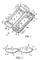
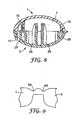
- Fig. 1 shows two elongate cover members 1, 3 that are used, in a manner to be described below, to form a cylindrical protective enclosure for a longitudinal cable splice (not shown).
- the cover members 1, 3 are molded components formed from a suitable plastics material, for example polypropylene or polyamide, and are joined together along their inner longitudinal edges 2 by a hinge 5.
- the hinge 5 is integrally-molded with the cover members 1, 3 and comprises a region of reduced thickness that defines the bending axis of the hinge. This type of hinge is well known and is often referred to as a "living" hinge.
- the cover members 1, 3 both include internal walls (described in greater detail below) that define central cavity regions 7, 9 respectively.
- the cavity regions 7, 9 together form a central enclosed cavity for containing the cable splice that is to be protected.
- latching tabs 11 project upwards from inside the outer longitudinal edge 10 of the upper cover member 1 so that they will slide into a latching space 10A behind the outer longitudinal edge 10 of the lower cover member 3 and engage in respective recesses 12.
- the lower cover member 3 is provided with pins 13 that engage in apertures 14 in the upper cover member 1. In that way, the stress placed on the hinge 5 when the splice enclosure is in use is limited and the risk that the latching tabs 11 will inadvertently disengage from the openings 12 is minimized.
- the cavity region 7 in the upper cover member 1 is defined between side walls 15 and double end walls 17 that stand up from the internal surface of the cover member.
- the side walls 15 are located slightly inside the inner and outer longitudinal edges 2, 10 of the cover member, and extend parallel thereto.
- the double end walls 17 extend between the ends of the side walls 15 and are arranged at a distance from the respective ends 19 of the cover member 1, thereby creating a space 20 at each end of the upper cover member: each of those spaces 20 is intended, when the splice enclosure is in use, to accommodate a respective upstanding cable strain-relief structure 21 formed at the corresponding end of the lower cover member 3.
- the strain-relief structures 21 will be described below.
- the space 17A between the two walls of each double end wall 17 provides a containment space for sealant material, also described below.
- the cavity region 9 in the lower cover member 3 is defined between side walls 22 and end walls 23 that stand up from the internal surface of the cover member.
- the side walls 22 are located slightly inside the inner longitudinal edge 2 of the cover member and the inner wall 10B of the latching space 10A, and extend parallel thereto.
- the end walls 23 extend between the ends of the side walls 22 and each is arranged at a distance from the respective strain-relief structure 21. The spaces that are thus formed around the cavity region 9, on the outside of the side and end walls 22, 23, provide containment spaces for sealant material as will be described below.
- the side walls 15 and the double end wall 17 of the cavity region 7 in the upper cover member 1 stand up above the level of the outer edge of the cover member and are positioned so that, when the cover members 1, 3 are folded together into the closed position, the walls 15, 17 will telescope into the containment space around the cavity region 9 in the lower cover member 3.
- the cable entry paths into the splice enclosure are further defined by semi-circular recesses 25B in the end walls of the cover member 1 and the end wall 17 of the cavity region 7.
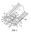
- each strain-relief structure 21 comprises three spaced walls 25, arranged parallel to the adjacent end 19 of the lower cover member 3.
- the walls 25 contain cable openings 25A that are offset relative to each other to define a convoluted cable entry path into the splice enclosure.
- the cable entry paths into the splice enclosure are further defined by semi-circular recesses 25B in the end walls of the cover member3 and the end wall 23 of the cavity region 9.
- Associated with the recess 25B in the end walls 23 are optional surfaces 26 for guiding a cable into the cavity region 9 and providing additional strain relief, if required.
- the splice enclosure comprising the cover members 1, 3 can be used without the addition of any sealant material (i.e. in the form shown in Fig. 1 and Fig. 3 ) to provide a basic level of protection against humidity for a longitudinal splice between two cables, in addition to protection against mechanical impact and cable strain.
- the cable splice is first prepared, and the cables are then placed on the lower cover member 3 with the splice itself positioned in the cavity region 9 and the cables extending out of opposite ends of the cover member along the paths defined by the openings 25A in the strain relief structures 21, and the recesses 25B in the walls 19, 17 and 23.
- the upper cover member 1 is then folded down onto the lower cover member 3, around the hinge 5, and latched in the closed position.
- the cable splice is now protected against mechanical impact and, to a basic level, against humidity by the cover members 1, 3 but is nevertheless readily accessible simply by unlatching the upper cover member and moving it to the open position.
- the convoluted cable paths defined by the openings 25A provide strain relief for the cables, and ensure the integrity of the splice.
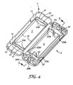
- sealant material 27 is provided in the containment spaces at the ends of the cavity regions 7, 9.
- the walls 23 of lower cover member 3 are extended outwards at each end to provide barriers 23A.
- recesses 15A are cut in the tops of the walls 15 of the upper cover member 1 to accommodate the tops of the barriers 23A when the splice enclosure is closed.
- the cable splice is then prepared and the cables are placed on the lower cover member 3 as described above and as illustrated in Fig. 6 , which shows the enclosure of Fig. 4 in the process of being used to protect a longitudinal splice between two cables 28.
- the cables are shown as comprising two pairs of wires 28A (although that is not essential) and they are positioned on the lower cover member 3 so that the connections 28B between the individual wires 28A of one cable and those of the other cable are located within the cavity region 9 with the cables 28 extending from opposite ends thereof, along the paths defined by the openings 25A in the strain relief structures 21, and the recesses 25B in the walls 19, and 23.
- the splice enclosure is then closed as described above, whereupon the tops of the barriers 23A in the lower cover member 3 locate in the respective recesses 15A in the upper cover member 1.
- the double walls 17 at the ends of the cavity region 7 (with the sealant material 27 between them) will telescope into the sealant material 27 at the ends of the cavity region 9 as illustrated in Fig. 5 , which shows a central longitudinal cross-section of the splice enclosure from which the cables have been omitted for clarity.
- the sealant material 27 at both ends of the inner cavity of the splice enclosure is compressed and brought into effective sealing contact with the cables and the adjacent surfaces of the cover members.
- the sealant material may also tend to flow out of the containment spaces and along the outside of the cables to a limited extent, thereby enhancing the sealing effect.
- the cable splice is now protected to a higher level against humidity and, as before, against mechanical impact and cable strain but is still readily accessible simply by unlatching the upper cover member and moving it to the open position.
- the sealant material 27 for the enclosure of Fig. 4 may be provided in the form of pre-shaped pieces of gel that are located in the containment spaces at the ends of the cavity regions 7, 9.
- the sealant material may be provided in liquid form, in which case it is poured into the containment spaces and cured there to a gel-like consistency before use. Any tendency for the liquid sealant material to overflow from the containment spaces through the adjacent recesses 25A, 25B can be limited by using a high viscosity sealant material with a short curing time.
- splice enclosure is then closed as described above, whereupon the side walls 15 of the cavity region 7 as well as the double end walls 17 (with the sealant material 27 between them) will telescope into the sealant material 29, 27 at, respectively, the sides and the ends of the cavity region 9 as illustrated in the cross-sectional views of Figs. 5 and 8 .
- the inner cavity of the splice enclosure is surrounded by compressed sealant material and the cable splice is protected to an even higher level against humidity (and, as before, against mechanical impact and-cable strain) but is still readily accessible simply by unlatching the upper cover member and moving it to the open position.
- the sealant material 27, 29 for the enclosure of Fig. 7 may be provided in the form of pre-shaped pieces of gel that are located in the containment spaces at the ends of the cavity region 7, and at the ends and sides of the -cavity region 9.
- the sealant material may be provided in liquid form, in which case it is poured into the containment spaces and cured there to a gel-like consistency before use.
- a particular advantage of the splice enclosures comprising cover members 1, 3 as described above is that one type of enclosure can be used to provide several levels of protection against humidity simply by the inclusion of sealant material at appropriate locations within the cover members. Indeed, the splice enclosure illustrated in Fig. 4 can be used to provide the three different levels of protection illustrated in Figs. 1 , 4 and 7 despite the fact that the barriers 23A are not required in every case. For each level of humidity protection, effective protection for the splice against mechanical impact and cable strain is also provided.
- the splice enclosures are of simple construction, and use comparatively few components so that they are easy to assemble in the field, even at difficult or inaccessible locations.
- the modification required to change the level of protection i.e. the addition of sealant material
- the maximum amount of sealant material ( Fig. 7 ) need be used only when absolutely necessary and is still less than that used in, for example, re-enterable splice enclosures in which the whole of the splice cavity is filled with sealant material. Consequently, the costs of splice enclosures comprising cover members 1, 3 as described above can be lower than those in which the whole of the splice cavity is filled with sealant material.
- the fact that the cavity regions 7, 9 are empty allows a greater number of splices to be accommodated within a single enclosure; provides better environmental conditions in which to locate the splice(s) long-term; and simplifies access to the splice(s) in the event of the enclosure being re-opened.
- the sealant material 27, 29 has sufficient long-term resilience to ensure, once it has been compressed by closing the cover members 1, 3, that effective sealing is maintained until the splice enclosure is re-opened.
- the sealant material permits the splice enclosure then to be re-sealed (and, if required, opened and re-sealed again several times) and to continue to provide the same level of protection for the cable splice.
- a suitable sealant material is described in US-B-7,214,735 . If required, however, one or more external resilient members can be positioned in known manner at suitable locations in the cover members 1, 3 to apply the required compressive force to the sealant material when the splice enclosure is closed.
- the single hinge 5 between the two cover members 1, 3 is replaced by two hinges 5A, 5B as illustrated in Fig. 9 . That modification enables the splice enclosure to be closed by moving each cover member through only 90° relative to the adjacent hinge, thereby reducing the strain placed on each hinge.
- a single hinge 5 is employed, as shown in Fig. 2 , it is not essential for the hinge to be integrally-molded with the cover members; as an alternative it could be a separate component in the form, for example, of a film or a tape that is insert molded or attached by adhesive. It is also possible to modify the form, location and number of the latches 11, 12 that are used to hold the cover members together in the closed position.
- strain-relief structures 21 in the splice enclosure, although convenient, will limit the size of cable with which the splice enclosure can be used.
- the strain-relief structures 21 can be omitted and conventional cable ties used instead.
- the strain-relief structures 21 can be designed to accommodate the largest-diameter cables with which the splice enclosure is intended to be used, and some additional mechanism can be provided to enable the enclosure to be used with smaller-diameter cables.
- each compartment 30 is provided with a seat 32 that is aligned with the cable opening 25A of the adjacent strain-relief structure 21 and provides support for a cable that enters the splice enclosure. If the cable is too small to be secured adequately by the strain-relief structure 21, it can be secured to the seat 32 by a cable tie (not shown) that is passed around the cable and the seat through an aperture 34 in the cover member 3.
- the cover member 1 is also extended at each end to the same extent as the cover member 3 so that the compartments 30 containing the seats 32 will be closed when the cover members 1, 3 are closed around a cable splice.
- the cable seats 32 can simply be provided as extensions of the cover member and remain exposed when the splice enclosure is closed.
- Fig. 10 also shows a further modification of the splice enclosure, in the form of two areas of weakness 36 in the cover member 3 (one within each of the -compartments 30) that can be pierced by screws to enable the enclosure to be secured to a flat surface if required.
- locations for screws can be provided in extensions of the cover member 3 so that they remain exposed and accessible when the splice enclosure is closed.
- Fig. 10 further illustrates that the cable openings/recesses 25A, 25B in the walls of the containment spaces at the ends of the cavity regions 7, 9 are all closed by breakable wall portions 26 prior to use of the splice enclosure.
- Those wall portions 26 allow liquid sealant material to be poured into the containment spaces up to the level of the top of the walls and retained during curing. Thereafter, because the wall portions 26 are breakable, they will be removed by the action of putting a cable in place in the associated openings/recesses 25A, 25B thereby enabling the cable to be effectively embedded in the sealant material.
- Similar breakable wall portions could be employed in any of the other splice enclosures described above with reference to the drawings.
- Fig. 10 also shows the provision of a raised continuation 40 adjacent the hinge 5 on the middle wall 25 of each of the strain-relief structures 21.
- Each of the raised continuations 40 is engageable in a respective aperture 41 on the other side of the hinge in the cover member 1, to provide additional protection for the hinge when the cover members 1, 3 are closed.
- a splice enclosure of the same general type as those illustrated in the drawings could be used to protect a so-called "pig tail", or butt, splice (i.e. a splice between cables that extend generally from the same direction, rather than from opposite directions as shown in Fig. 6 ).
- the splice enclosure (including the strain-relief structures 21) would require modification to permit the cables to enter the enclosure generally from the same direction, rather than from opposite directions as illustrated in the drawings.
Landscapes
- Physics & Mathematics (AREA)
- General Physics & Mathematics (AREA)
- Optics & Photonics (AREA)
- Cable Accessories (AREA)
- Light Guides In General And Applications Therefor (AREA)
- Input Circuits Of Receivers And Coupling Of Receivers And Audio Equipment (AREA)
- Piezo-Electric Or Mechanical Vibrators, Or Delay Or Filter Circuits (AREA)
- Electrical Discharge Machining, Electrochemical Machining, And Combined Machining (AREA)
- Mechanical Coupling Of Light Guides (AREA)
- Housing For Livestock And Birds (AREA)
- Treating Waste Gases (AREA)
- Accessories Of Cameras (AREA)
- Studio Devices (AREA)
- Structure And Mechanism Of Cameras (AREA)
Abstract
Description
- The present invention relates to an enclosure for a splice between cables, the enclosure being of the type that can be re-opened, re-enterable, to permit access to the cable splice when required and, preferably, then re-sealed. The cable may, for example, be a telecommunications cable, a power cable or an optical fibre cable.
- The cable splice may, for example, be a longitudinally-extending splice (i.e. a splice between cables that extend generally from opposite directions) or a so-called "pigtail", or butt, splice (i.e. a splice between cables that extend generally from the same direction).
- A cable splice will generally require protection from the effects of the environment in which it is located and, more especially, will require protection against mechanical impact and the entry of moisture. Protection of the cables against strain will often also be required. Many different enclosures providing different levels of protection for cable splices are already available, including so-called re-enterable enclosures that can be re-opened to permit access to the splice whenever required.
- Known re-enterable splice enclosures often take the form of a two-part re-openable housing that defines a cavity around the splice and contains a sealant material. The housing provides protection for the splice against mechanical impact and, in combination with the sealant material, protects the cavity to a required level against the entry of moisture while permitting access to the splice when the housing is re-opened. In some cases, the cavity is completely filled with sealant material (see, for example, the splice enclosures described in
U.S.-B-6,169,250 and, in other cases, the sealant material is pre-formed by molding to particular shapes for use in cable bushings that are located at the ends of the housing (see, for example, the splice enclosures described inWO-A 02/063736 -
FR-A-2 770 048 EP-A-0 233 417 , andFR-A-2 789 816 - The present invention is concerned with providing a re-enterable splice enclosure that is capable of providing adequate protection for a cable splice against mechanical impact and the entry of moisture without requiring the cavity surrounding the splice to be filled with any suitable sealant material, and without requiring the sealant material to be pre-formed to comparatively complex shapes for use in cable bushings. The invention is, accordingly, also concerned with providing a re-enterable splice enclosure that is capable of providing adequate protection for a cable splice against mechanical impact and the entry of moisture while using a comparatively small amount of sealant material and while being comparatively simple to assemble.
- The present invention provides a re-enterable enclosure for a splice between cables as defined in
claim 1. The dependent claims relate to individual embodiments, respectively. - Advantageously, at least one of the cover members comprises strain-relief members associated with cable entry paths into the cavity. The enclosure is then capable of providing the splice with protection against the effects of cable strain in addition to that provided, by the cover members, against mechanical impact and that provided, by the cover members in combination with any sealant material in the containment spaces, against the entry of moisture.
- By way of example only, splice enclosures in accordance with the invention will be described with reference to the accompanying drawings in which:
-
Fig. 1 is a perspective view of an exemplary splice enclosure in an open condition, showing the inside of the cover members; -
Fig. 2 is an end view of the splice enclosure ofFig. 1 in the direction of the arrow II; -
Fig. 3 is an enlarged view of one end of one of the cover members ofFig. 1 ; -
Fig. 4 is similar toFig. 1 but shows another exemplary splice enclosure with sealant material contained in the cover members; -
Fig. 5 shows a longitudinal cross-section taken along line 5-5 of the splice enclosure ofFig. 4 in a closed condition; -
Fig. 6 shows the splice enclosure ofFig. 4 in an open condition and ready to be closed around a cable splice; -
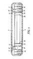
Fig. 7 is similar toFig. 1 and shows sealant material contained in the cover members; -
Fig. 8 is a cross-sectional view of the splice enclosure ofFig. 7 in the direction of the arrow 8-8; -
Fig. 9 is an end view on an enlarged scale of part of a splice enclosure, illustrating a modified hinge; and -
Fig. 10 is a perspective view of yet another splice enclosure in an open condition, showing the inside of the cover members. -
Fig. 1 shows twoelongate cover members cover members longitudinal edges 2 by ahinge 5. As illustrated, thehinge 5 is integrally-molded with thecover members - The
cover members central cavity regions cover members hinge 5 and brought into engagement with each other to close the splice enclosure, thecavity regions cover members latching tabs 11 project upwards from inside the outerlongitudinal edge 10 of theupper cover member 1 so that they will slide into alatching space 10A behind the outerlongitudinal edge 10 of thelower cover member 3 and engage inrespective recesses 12. In addition, to reduce the possibility of any relative movement between thecover members lower cover member 3 is provided withpins 13 that engage inapertures 14 in theupper cover member 1. In that way, the stress placed on thehinge 5 when the splice enclosure is in use is limited and the risk that thelatching tabs 11 will inadvertently disengage from theopenings 12 is minimized. - The
cavity region 7 in theupper cover member 1 is defined betweenside walls 15 anddouble end walls 17 that stand up from the internal surface of the cover member. Theside walls 15 are located slightly inside the inner and outerlongitudinal edges double end walls 17 extend between the ends of theside walls 15 and are arranged at a distance from therespective ends 19 of thecover member 1, thereby creating aspace 20 at each end of the upper cover member: each of thosespaces 20 is intended, when the splice enclosure is in use, to accommodate a respective upstanding cable strain-relief structure 21 formed at the corresponding end of thelower cover member 3. The strain-relief structures 21 will be described below. Thespace 17A between the two walls of eachdouble end wall 17 provides a containment space for sealant material, also described below. - The
cavity region 9 in thelower cover member 3 is defined betweenside walls 22 andend walls 23 that stand up from the internal surface of the cover member. Theside walls 22 are located slightly inside the innerlongitudinal edge 2 of the cover member and theinner wall 10B of thelatching space 10A, and extend parallel thereto. Theend walls 23 extend between the ends of theside walls 22 and each is arranged at a distance from the respective strain-relief structure 21. The spaces that are thus formed around thecavity region 9, on the outside of the side andend walls - The
side walls 15 and thedouble end wall 17 of thecavity region 7 in theupper cover member 1 stand up above the level of the outer edge of the cover member and are positioned so that, when thecover members walls cavity region 9 in thelower cover member 3. - The cable entry paths into the splice enclosure are further defined by
semi-circular recesses 25B in the end walls of thecover member 1 and theend wall 17 of thecavity region 7. - Referring now to
Fig. 3 , which is an enlarged view of one end of thelower cover member 3, it can be seen that each strain-relief structure 21 comprises three spacedwalls 25, arranged parallel to theadjacent end 19 of thelower cover member 3. Thewalls 25 containcable openings 25A that are offset relative to each other to define a convoluted cable entry path into the splice enclosure. The cable entry paths into the splice enclosure are further defined bysemi-circular recesses 25B in the end walls of the cover member3 and theend wall 23 of thecavity region 9. Associated with therecess 25B in theend walls 23 areoptional surfaces 26 for guiding a cable into thecavity region 9 and providing additional strain relief, if required. - The splice enclosure comprising the
cover members Fig. 1 andFig. 3 ) to provide a basic level of protection against humidity for a longitudinal splice between two cables, in addition to protection against mechanical impact and cable strain. The cable splice is first prepared, and the cables are then placed on thelower cover member 3 with the splice itself positioned in thecavity region 9 and the cables extending out of opposite ends of the cover member along the paths defined by theopenings 25A in thestrain relief structures 21, and therecesses 25B in thewalls upper cover member 1 is then folded down onto thelower cover member 3, around thehinge 5, and latched in the closed position. The cable splice is now protected against mechanical impact and, to a basic level, against humidity by thecover members openings 25A provide strain relief for the cables, and ensure the integrity of the splice. - Referring to
Fig. 4 , if the cable splice requires a higher level of protection against humidity,sealant material 27 is provided in the containment spaces at the ends of thecavity regions cavity region 9, that thesealant material 27 is retained within the containment spaces at the ends of the cavity (and does not enter the containment spaces at the sides), thewalls 23 oflower cover member 3 are extended outwards at each end to providebarriers 23A. As a consequence,recesses 15A are cut in the tops of thewalls 15 of theupper cover member 1 to accommodate the tops of thebarriers 23A when the splice enclosure is closed. - The cable splice is then prepared and the cables are placed on the
lower cover member 3 as described above and as illustrated inFig. 6 , which shows the enclosure ofFig. 4 in the process of being used to protect a longitudinal splice between twocables 28. The cables are shown as comprising two pairs ofwires 28A (although that is not essential) and they are positioned on thelower cover member 3 so that theconnections 28B between theindividual wires 28A of one cable and those of the other cable are located within thecavity region 9 with thecables 28 extending from opposite ends thereof, along the paths defined by theopenings 25A in thestrain relief structures 21, and therecesses 25B in thewalls barriers 23A in thelower cover member 3 locate in therespective recesses 15A in theupper cover member 1. At the same time, thedouble walls 17 at the ends of the cavity region 7 (with thesealant material 27 between them) will telescope into thesealant material 27 at the ends of thecavity region 9 as illustrated inFig. 5 , which shows a central longitudinal cross-section of the splice enclosure from which the cables have been omitted for clarity. As a result, thesealant material 27 at both ends of the inner cavity of the splice enclosure is compressed and brought into effective sealing contact with the cables and the adjacent surfaces of the cover members. Depending on its nature, the sealant material may also tend to flow out of the containment spaces and along the outside of the cables to a limited extent, thereby enhancing the sealing effect. The cable splice is now protected to a higher level against humidity and, as before, against mechanical impact and cable strain but is still readily accessible simply by unlatching the upper cover member and moving it to the open position. - The
sealant material 27 for the enclosure ofFig. 4 may be provided in the form of pre-shaped pieces of gel that are located in the containment spaces at the ends of thecavity regions adjacent recesses - Referring to
Fig. 7 , if the cable splice requires an even higher level of protection against humidity,additional sealant material 29 is also provided in the containment spaces along the sides of thecavity region 9 before the spliced cables are placed on thelower cover member 3 as described above. In this case, thebarrier 23A and associatedrecesses 15A ofFig. 4 are not required and can be omitted. The splice enclosure is then closed as described above, whereupon theside walls 15 of thecavity region 7 as well as the double end walls 17 (with thesealant material 27 between them) will telescope into thesealant material cavity region 9 as illustrated in the cross-sectional views ofFigs. 5 and8 . As a result, the inner cavity of the splice enclosure is surrounded by compressed sealant material and the cable splice is protected to an even higher level against humidity (and, as before, against mechanical impact and-cable strain) but is still readily accessible simply by unlatching the upper cover member and moving it to the open position. - As described above, the
sealant material Fig. 7 may be provided in the form of pre-shaped pieces of gel that are located in the containment spaces at the ends of thecavity region 7, and at the ends and sides of the -cavity region 9. Alternatively, the sealant material may be provided in liquid form, in which case it is poured into the containment spaces and cured there to a gel-like consistency before use. - A particular advantage of the splice enclosures comprising
cover members Fig. 4 can be used to provide the three different levels of protection illustrated inFigs. 1 ,4 and7 despite the fact that thebarriers 23A are not required in every case. For each level of humidity protection, effective protection for the splice against mechanical impact and cable strain is also provided. - The splice enclosures are of simple construction, and use comparatively few components so that they are easy to assemble in the field, even at difficult or inaccessible locations.
- The modification required to change the level of protection (i.e. the addition of sealant material) can be easily carried out by the manufacturer or installer, particularly when a liquid sealant material is used because there is then no need to stock pieces of gel that are preformed to a particular shape. The maximum amount of sealant material (
Fig. 7 ) need be used only when absolutely necessary and is still less than that used in, for example, re-enterable splice enclosures in which the whole of the splice cavity is filled with sealant material. Consequently, the costs of splice enclosures comprisingcover members cavity regions - Because only one sealant material is used in the splice enclosures shown in
Figs. 4 and7 of the drawings, there are no sealing problems associated with interfaces between different sealing materials (for example, at the junction of thesealant materials Fig. 7 or at the junction between thesealant materials 27 in the upper andlower cover members 1, 3). Moreover, the particular construction of the splice enclosure (which, as described, causes thedouble end walls 17 in theupper cover member 1, and thesealant material 27 contained therein, to telescope into thesealant material 27 in thelower cover member 3 when the enclosure is closed) ensures that thecables 28 are entirely surrounded by thesealant material 27 in the region immediately outside thecentral cavity sealant material 27 in theupper cover member 1 were simply in face-to-face contact with thesealant material 27 in the lower cover member and which, if present, could allow moisture to enter thecentral cavity - Preferably, the
sealant material cover members US-B-7,214,735 . If required, however, one or more external resilient members can be positioned in known manner at suitable locations in thecover members - It will be appreciated that various modifications could be made to the construction of the
cover members single hinge 5 between the twocover members hinges Fig. 9 . That modification enables the splice enclosure to be closed by moving each cover member through only 90° relative to the adjacent hinge, thereby reducing the strain placed on each hinge. When asingle hinge 5 is employed, as shown inFig. 2 , it is not essential for the hinge to be integrally-molded with the cover members; as an alternative it could be a separate component in the form, for example, of a film or a tape that is insert molded or attached by adhesive. It is also possible to modify the form, location and number of thelatches - The provision of the strain-
relief structures 21 in the splice enclosure, although convenient, will limit the size of cable with which the splice enclosure can be used. For use with larger-diameter cables, the strain-relief structures 21 can be omitted and conventional cable ties used instead. Alternatively, the strain-relief structures 21 can be designed to accommodate the largest-diameter cables with which the splice enclosure is intended to be used, and some additional mechanism can be provided to enable the enclosure to be used with smaller-diameter cables.Fig. 10 , for example, shows a splice enclosure in which each of the strain-relief structures 21 is designed to accommodate a five-pair cable, and thecover member 3 is extended at each end to providecompartments 30 in which smaller diameter cables (for example, two-pair cables) can be secured using conventional cable ties. For that purpose, eachcompartment 30 is provided with aseat 32 that is aligned with thecable opening 25A of the adjacent strain-relief structure 21 and provides support for a cable that enters the splice enclosure. If the cable is too small to be secured adequately by the strain-relief structure 21, it can be secured to theseat 32 by a cable tie (not shown) that is passed around the cable and the seat through anaperture 34 in thecover member 3. - With the benefit of the teachings of this patent, one of skill in the art could apply the present invention to any size cable or any desired pair count.
- In the splice enclosure shown in
Fig. 10 , thecover member 1 is also extended at each end to the same extent as thecover member 3 so that thecompartments 30 containing theseats 32 will be closed when thecover members -
Fig. 10 also shows a further modification of the splice enclosure, in the form of two areas ofweakness 36 in the cover member 3 (one within each of the -compartments 30) that can be pierced by screws to enable the enclosure to be secured to a flat surface if required. As a further alternative, locations for screws can be provided in extensions of thecover member 3 so that they remain exposed and accessible when the splice enclosure is closed. -
Fig. 10 further illustrates that the cable openings/recesses 25A, 25B in the walls of the containment spaces at the ends of thecavity regions breakable wall portions 26 prior to use of the splice enclosure. Thosewall portions 26 allow liquid sealant material to be poured into the containment spaces up to the level of the top of the walls and retained during curing. Thereafter, because thewall portions 26 are breakable, they will be removed by the action of putting a cable in place in the associated openings/recesses 25A, 25B thereby enabling the cable to be effectively embedded in the sealant material. Similar breakable wall portions could be employed in any of the other splice enclosures described above with reference to the drawings. -
Fig. 10 also shows the provision of a raisedcontinuation 40 adjacent thehinge 5 on themiddle wall 25 of each of the strain-relief structures 21. Each of the raisedcontinuations 40 is engageable in arespective aperture 41 on the other side of the hinge in thecover member 1, to provide additional protection for the hinge when thecover members - It will further be appreciated that a splice enclosure of the same general type as those illustrated in the drawings could be used to protect a so-called "pig tail", or butt, splice (i.e. a splice between cables that extend generally from the same direction, rather than from opposite directions as shown in
Fig. 6 ). In that case, the splice enclosure (including the strain-relief structures 21) would require modification to permit the cables to enter the enclosure generally from the same direction, rather than from opposite directions as illustrated in the drawings. - Further modification of the cable entry paths of any of the splice enclosures described above with reference to the drawings would enable protection to be provided for splices between different numbers of cables, for example a longitudinal splice between one cable extending from one direction and two cables extending from the other direction.
Claims (13)
- A re-enterable enclosure for a splice between cables, the enclosure comprising:first and second cover members (1,3) with internal walls (17,23,25) that are configured to form a cavity (7,9) for enclosing the cable splice when the cover members (1,3) are engaged with each other in a closed position, wherein:(i) at least one of the cover members (1,3) has internal walls (17,23,25) that are configured to define a containment space (17A) containing sealant material (27), that at least partly surround the cavity (7,9), and(ii) at least one internal wall (17,23,25) in one cover member (1,3) telescopes into a containment space (17A) in the other cover member (1,3), thereby to compress sealant material (27) contained therein, when the cover members (1,3) are engaged with each other in the closed position,
characterized in that(iii) there are internal walls (17,23,25) configured to define containment spaces (17A) in both cover members (1,3), and in which the containment space in one cover member (1,3) telescopes into the containment space (17A) in the other cover member (1,3), to compress sealant material (27) contained in both containment spaces (17A) when the cover members (1,3) are engaged with each other in the closed position - A splice enclosure as claimed in claim 1, in which the internal walls (17,23,25) are configured to define containment spaces (17A) that surround cable entry paths into the cavity (7,9), and wherein said cable paths traverse said containment spaces (17A).
- A splice enclosure as claimed in claim 1 or 2, in which at least one of the containment spaces (17A) contains a sealant material (27) that has been poured into the containment space (17A) and then cured.
- A splice enclosure as claimed in any one of claims 1 to 3, in which the containment spaces (17A) all contain the same sealant material (27).
- A splice enclosure as claimed in any one of claims 1 to 4, in which the cavity (7,9) for enclosing the cable splice is essentially free of sealant material.
- A splice enclosure as claimed in any one of claims 1 to 5, in which at least one of the cover members (1,3) comprises strain-relief members (21) associated with said cable entry paths.
- A splice enclosure as claimed in any one of claims 1 to 6, in which the cavity (7,9) is of elongate form, and the splice enclosure comprises cable entry paths into the cavity (7,9) from opposed ends (19) thereof.
- A splice enclosure as claimed in claim 7, in which the internal walls (17,23,25) are configured to define transverse containment spaces (17A) at said opposed ends (19) of the cavity (7,9).
- A splice enclosure as claimed in claim 8, in which the cable entry paths traverse said transverse containment spaces (17A).
- A splice enclosure as claimed in claim 7, in which the internal walls (17,23,25) in both cover members (1,3) are configured to provide longitudinal containment spaces (17A) that extend along both sides (15,22) of the cavity (7,9) of the respective cover member (1,3) between the opposed ends (19) thereof.
- A splice enclosure as claimed in any one of claims 1 to 10, in which the cover members (1,3) are joined to each other by at least one hinge (5).
- A splice enclosure as claimed in any one of claims 1 to 10, in which the cover members (1,3) are releasably engageable with each other.
- A splice enclosure as claimed in any one of claims 1 to 12, in which the cover members (1,3) are molded components.
Applications Claiming Priority (2)
| Application Number | Priority Date | Filing Date | Title |
|---|---|---|---|
| US10/770,377 US7141738B2 (en) | 2004-02-02 | 2004-02-02 | Re-enterable splice enclosure |
| PCT/US2005/000107 WO2005076427A1 (en) | 2004-02-02 | 2005-01-04 | Re-enterable splice enclosure |
Publications (2)
| Publication Number | Publication Date |
|---|---|
| EP1711989A1 EP1711989A1 (en) | 2006-10-18 |
| EP1711989B1 true EP1711989B1 (en) | 2008-05-14 |
Family
ID=34808317
Family Applications (1)
| Application Number | Title | Priority Date | Filing Date |
|---|---|---|---|
| EP05704941A Active EP1711989B1 (en) | 2004-02-02 | 2005-01-04 | Re-enterable splice enclosure |
Country Status (16)
| Country | Link |
|---|---|
| US (1) | US7141738B2 (en) |
| EP (1) | EP1711989B1 (en) |
| JP (1) | JP4749342B2 (en) |
| CN (1) | CN100555783C (en) |
| AT (1) | ATE395739T1 (en) |
| AU (1) | AU2005211099A1 (en) |
| BR (1) | BRPI0507368B1 (en) |
| CA (1) | CA2554960A1 (en) |
| DE (1) | DE602005006741D1 (en) |
| DK (1) | DK1711989T3 (en) |
| EG (1) | EG24471A (en) |
| MY (1) | MY139820A (en) |
| NO (1) | NO20063625L (en) |
| RU (1) | RU2361347C2 (en) |
| TW (1) | TW200537778A (en) |
| WO (1) | WO2005076427A1 (en) |
Cited By (2)
| Publication number | Priority date | Publication date | Assignee | Title |
|---|---|---|---|---|
| MY139820A (en) * | 2004-02-02 | 2009-10-30 | 3M Innovative Properties Co | Re-enterable splice enclosure |
| EP2182601A1 (en) | 2008-10-30 | 2010-05-05 | 3M Innovative Properties Company | Sealing enclosure |
Families Citing this family (63)
| Publication number | Priority date | Publication date | Assignee | Title |
|---|---|---|---|---|
| US7273984B2 (en) * | 2005-07-11 | 2007-09-25 | Twins Investments Company | Outdoor cord connection cover apparatus |
| CN101170247B (en) * | 2006-10-27 | 2010-05-19 | 3M新设资产公司 | Re-accessible connector enclosing cover |
| US7618269B2 (en) * | 2007-02-28 | 2009-11-17 | Hubbell Incorporated | Compliant cap |
| US7453042B2 (en) * | 2007-04-09 | 2008-11-18 | Andrew Llc | Cable and apparatus interconnection close quarters environmental seal |
| JP2009020221A (en) * | 2007-07-11 | 2009-01-29 | Fujikura Ltd | Optical closure and method of optical wiring from optical cable assembly to subscriber's house |
| US7562864B2 (en) * | 2007-10-09 | 2009-07-21 | Robbins Iii Edward S | Fence splice cover assembly |
| US7536075B2 (en) * | 2007-10-22 | 2009-05-19 | Adc Telecommunications, Inc. | Wavelength division multiplexing module |
| US7885505B2 (en) | 2007-10-22 | 2011-02-08 | Adc Telecommunications, Inc. | Wavelength division multiplexing module |
| FR2926166B1 (en) * | 2008-01-08 | 2010-06-11 | Ge Energy Products France Snc | KIT OF TEMPERATURE SENSORS, IN PARTICULAR FOR COMBUSTION TURBINE. |
| US7697812B2 (en) * | 2008-01-18 | 2010-04-13 | 3M Innovative Properties Company | Enclosure and organizer for telecommunication lines and splices |
| US8107816B2 (en) | 2008-01-29 | 2012-01-31 | Adc Telecommunications, Inc. | Wavelength division multiplexing module |
| DE102008051482A1 (en) * | 2008-04-01 | 2009-10-08 | Zumtobel Lighting Gmbh | Strain relief device |
| SE0850021L (en) * | 2008-09-23 | 2009-12-29 | Syntune Ab | Waveguide for low reflex switch-off. |
| WO2010059619A2 (en) * | 2008-11-18 | 2010-05-27 | Tyco Electronics Corporation | Sealant-filled enclosures and methods for environmentally protecting a connection |
| CA2988835C (en) * | 2008-11-18 | 2020-01-21 | Tyco Electronics Corporation | Sealant-filled enclosures and methods for environmentally protecting a connection |
| TWI420768B (en) * | 2009-02-26 | 2013-12-21 | Chi Yu Fen | Communication cable connection box with flexible rubber shrink tube waterproof device |
| MX2012010844A (en) * | 2010-03-29 | 2012-10-15 | Afl Telecommunications Llc | High fiber count package inner module. |
| CN102221735B (en) * | 2010-04-16 | 2013-07-17 | 泰科电子(上海)有限公司 | Cable connector box |
| DE202010006582U1 (en) * | 2010-05-07 | 2010-08-05 | CCS Technology, Inc., Wilmington | Inline cable sleeve |
| US9012774B2 (en) * | 2010-06-21 | 2015-04-21 | 3M Innovative Properties Company | Sealing member for an enclosure |
| CN102331609B (en) * | 2010-07-13 | 2015-05-27 | 泰科电子(上海)有限公司 | Optical fiber terminal box |
| CN201789149U (en) * | 2010-08-10 | 2011-04-06 | 泰科电子(上海)有限公司 | Sealing device for sealing connecting piece |
| CN201829633U (en) * | 2010-08-18 | 2011-05-11 | 泰科电子(上海)有限公司 | Sealed junction box |
| BR112013007515A2 (en) | 2010-10-19 | 2020-08-04 | 3M Innovative Properties Company | housing for a cable connection |
| RU2556943C2 (en) * | 2010-11-10 | 2015-07-20 | Эмерсон Клаймит Текнолоджиз, Инк. | Compressor assembly and casing for its electric components |
| US8476540B2 (en) | 2010-12-14 | 2013-07-02 | Trystar, Inc. | Shelter for portable electrical inlets/outlets |
| WO2013109305A1 (en) | 2011-08-19 | 2013-07-25 | Aerovironment, Inc. | Water-tight compartment with removable hatch and two-sided gel seal for multiple conduit access |
| US8960973B1 (en) * | 2011-10-06 | 2015-02-24 | Cooper Technologies Company | Splice enclosure for luminaires |
| US9480177B2 (en) | 2012-07-27 | 2016-10-25 | Emerson Climate Technologies, Inc. | Compressor protection module |
| WO2014035611A1 (en) * | 2012-08-30 | 2014-03-06 | 3M Innovative Properties Company | Sealed fiber optic splice tray |
| US9326391B2 (en) | 2012-08-31 | 2016-04-26 | Apple Inc. | Combined audio jack and mobile electronic device enclosure |
| US9594227B2 (en) | 2013-05-09 | 2017-03-14 | CommScope Connectivity Belgium BVBA | Sealing block with stackable sealing elements |
| US11098502B2 (en) * | 2014-05-15 | 2021-08-24 | Steven Joseph Jaworski | Tamper proof cable lock |
| US9395509B2 (en) | 2014-06-23 | 2016-07-19 | Commscope Technologies Llc | Fiber cable fan-out assembly and method |
| US9363343B2 (en) * | 2014-08-29 | 2016-06-07 | Apple Inc. | Audio jack connector integrated into enclosure |
| ES1132305Y (en) * | 2014-10-22 | 2015-01-28 | Simon S A U | Quick flanging device for electrical connections |
| US10054753B2 (en) | 2014-10-27 | 2018-08-21 | Commscope Technologies Llc | Fiber optic cable with flexible conduit |
| AT517416B1 (en) * | 2015-05-06 | 2017-06-15 | Gebauer & Griller Kabelwerke Ges M B H | CABLE AND METHOD FOR PRODUCING A CABLE |
| AU2015207954C1 (en) | 2015-07-31 | 2022-05-05 | Adc Communications (Australia) Pty Limited | Cable breakout assembly |
| JP6342859B2 (en) * | 2015-08-18 | 2018-06-13 | 矢崎総業株式会社 | Optical connector |
| US11131821B2 (en) | 2016-03-18 | 2021-09-28 | Commscope Technologies Llc | Optic fiber cable fanout conduit arrangements; components, and methods |
| US10890730B2 (en) | 2016-08-31 | 2021-01-12 | Commscope Technologies Llc | Fiber optic cable clamp and clamp assembly |
| CN109716194B (en) | 2016-10-13 | 2021-07-16 | 康普技术有限责任公司 | Fiber optic branch transition assembly including epoxy plug and cable strain relief |
| JP6466983B2 (en) | 2017-03-22 | 2019-02-06 | 京セラ株式会社 | connector |
| USD960114S1 (en) * | 2017-04-20 | 2022-08-09 | University Of Tennessee Research Foundation | Tampering detection enclosure |
| USD826875S1 (en) * | 2017-04-20 | 2018-08-28 | University Of Tennessee Research Foundation | Tampering detection clamping box for ingress and egress lines |
| USD960115S1 (en) * | 2017-04-20 | 2022-08-09 | University Of Tennessee Research Foundation | Tampering detection enclosure |
| CN110622051A (en) | 2017-05-08 | 2019-12-27 | 康普技术有限责任公司 | Optical fiber branch transition assembly |
| USD848992S1 (en) * | 2017-05-26 | 2019-05-21 | Samsung Electronics Co., Ltd. | Connecting device for wireless communications |
| US10283954B2 (en) * | 2017-07-28 | 2019-05-07 | Nicholas T. Tavare | Connection shield for power distribution networks |
| WO2019190760A1 (en) | 2018-03-29 | 2019-10-03 | Corning Research & Development Corporation | Pre-mold assembly for branched optical cable and related method |
| CA3099706A1 (en) | 2018-05-09 | 2019-11-14 | Afl Telecommunications Llc | Butt closures and bases therefor |
| IT201800005665A1 (en) * | 2018-05-24 | 2019-11-24 | CONNECTION BOX, IN PARTICULAR FOR THE SEALING AND INSULATION OF ELECTRICAL AND SIMILAR CONNECTIONS | |
| CN109217227A (en) * | 2018-08-15 | 2019-01-15 | 深圳供电局有限公司 | Screw rod reinforced high-voltage cable intermediate joint protective shell |
| CN108879578A (en) * | 2018-08-16 | 2018-11-23 | 深圳供电局有限公司 | Stackable cable intermediate joint protective shell |
| US12113342B2 (en) | 2019-03-13 | 2024-10-08 | Commscope Technologies Llc | Re-enterable enclosure with environmental sealing |
| JP7272032B2 (en) * | 2019-03-20 | 2023-05-12 | 住友電装株式会社 | connector |
| US20220302647A1 (en) * | 2019-06-05 | 2022-09-22 | Tyco Fire Products Lp | Clamping connector |
| US11515696B2 (en) * | 2019-12-17 | 2022-11-29 | Te Connectivity Solutions Gmbh | Electrical component enclosure with injected seal and method |
| US10996414B1 (en) | 2020-03-23 | 2021-05-04 | Afl Telecommunications Llc | Butt closures and bases therefor |
| US11657929B2 (en) * | 2020-04-02 | 2023-05-23 | Commscope Technologies Llc | Cable cuffs for multiple sized cables |
| US12078846B2 (en) | 2020-11-30 | 2024-09-03 | Afl Telecommunications Llc | Butt closures and bases therefor |
| CN113451804A (en) * | 2021-06-30 | 2021-09-28 | 贵州电网有限责任公司 | High-reliability multifunctional interface suitable for 500kV relay protection |
Family Cites Families (42)
| Publication number | Priority date | Publication date | Assignee | Title |
|---|---|---|---|---|
| US3183302A (en) * | 1962-01-08 | 1965-05-11 | Jasper Blackburn Corp | Cover for an electrical connector |
| US4449015A (en) * | 1981-05-18 | 1984-05-15 | Proto Production Plastics, Inc. | Connector cover with multiple mounting means |
| US4423918A (en) | 1981-08-18 | 1984-01-03 | Minnesota Mining & Manufacturing Company | Re-enterable service wire splice closure |
| US4451696A (en) * | 1982-11-15 | 1984-05-29 | Amp Incorporated | Toolless splice sealant device |
| US4610738A (en) * | 1985-01-04 | 1986-09-09 | Raychem Corporation | Encapsulating a splice with a gel-filled case |
| KR930011233B1 (en) * | 1985-01-04 | 1993-11-29 | 레이켐 코포레이션 | Splice case |
| ATE50095T1 (en) | 1986-02-21 | 1990-02-15 | Morel Atel Electromec | SLEEVES OF PLASTIC MATERIAL FOR PROTECTING A SPLICE OF ELECTRICAL CABLES OR COMMUNICATIONS CABLES, AND METHOD OF MAKING THE SEALING OF SUCH SLEEVES. |
| JP2510577B2 (en) | 1987-05-13 | 1996-06-26 | 東芝シリコ−ン株式会社 | Curable silicone gel composition |
| US4849580A (en) | 1988-02-11 | 1989-07-18 | Minnesota Mining And Manufacturing Company | Environmental protection closure for wire splices; and method |
| US4879436A (en) * | 1988-08-18 | 1989-11-07 | Northern Telecom Limited | Closure for telecommunications cable |
| TR24079A (en) | 1988-11-09 | 1991-03-01 | Raychem Sa Nv | CLOSING LUGGAGE |
| JPH04503825A (en) * | 1989-03-01 | 1992-07-09 | レイケム・コーポレイション | Method for curing organopolysiloxane compositions and articles made therefrom |
| JPH0353466A (en) * | 1989-07-19 | 1991-03-07 | Three Bond Co Ltd | Coating member for joint member |
| GB9112181D0 (en) | 1991-06-06 | 1991-07-24 | Raychem Sa Nv | Cable sealing |
| AU673143B2 (en) | 1991-06-07 | 1996-10-31 | Raychem Corporation | Hinged gel-filled security and environmental protection device |
| US5310075A (en) * | 1992-11-27 | 1994-05-10 | Distribution Control Systems, Inc. | Waterproof, gasketless enclosure |
| EP0722624B1 (en) | 1993-10-07 | 1998-09-02 | N.V. Raychem S.A. | Environmental protection |
| GB9322929D0 (en) | 1993-11-08 | 1994-01-05 | Raychem Sa Nv | Cable closure |
| MY112885A (en) | 1993-12-01 | 2001-10-31 | N V Raychem S A | Sealing device. |
| US5397859A (en) * | 1993-12-10 | 1995-03-14 | The Whitaker Corporation | Enclosure with sealant for spliced coaxial cables |
| DE69414002D1 (en) | 1993-12-22 | 1998-11-19 | Raychem Ltd | CABLE CONNECTION |
| GB9403838D0 (en) | 1994-02-28 | 1994-04-20 | Raychem Sa Nv | Environmental sealing |
| JPH07245030A (en) * | 1994-03-07 | 1995-09-19 | Sumitomo Wiring Syst Ltd | Grommet |
| US5529508A (en) * | 1994-04-01 | 1996-06-25 | Raychem Corporation | Sealing member |
| US5525073A (en) | 1994-06-01 | 1996-06-11 | Raychem Corporation | Environmental protection device with manually operated latch mechanism |
| US5777268A (en) | 1995-10-06 | 1998-07-07 | Raychem Corporation | Splice closure for buried telecommunications cables |
| GB9505458D0 (en) | 1995-03-17 | 1995-05-03 | Raychem Ltd | An article for protecting a multi-conductor connector |
| DE59500604D1 (en) | 1995-03-22 | 1997-10-09 | Sonderhoff Ernst Fa | Process for producing a foamed or non-foamed soft-elastic silicone elastomer, in particular for sealing purposes |
| US5763835A (en) | 1995-11-01 | 1998-06-09 | Raychem Corporation | Gel-filled closure |
| ID15837A (en) | 1996-01-24 | 1997-08-14 | Raychem Sa Nv | CABLE COVER |
| US5844171A (en) * | 1997-04-22 | 1998-12-01 | Mev Corporation | Environmentally enclosed cable splice |
| JPH1141781A (en) * | 1997-07-22 | 1999-02-12 | Harness Sogo Gijutsu Kenkyusho:Kk | Waterproof case at wire joint |
| FR2770048B1 (en) | 1997-10-16 | 1999-12-31 | Rxs Morel Accessoires De Cable | SPLICE PROTECTION DEVICE AND METHOD FOR ALLOWING THE PLACEMENT OF SUCH A DEVICE |
| JPH11204982A (en) * | 1998-01-08 | 1999-07-30 | Takeuchi Kogyo Kk | Noise absorber |
| GB9815080D0 (en) | 1998-07-10 | 1998-09-09 | Dow Corning Sa | Compressible silicone composition |
| FR2789816B1 (en) | 1999-02-17 | 2001-03-30 | Rxs Morel Accessoires De Cable | SPLICE PROTECTION DEVICE |
| US6169250B1 (en) * | 1999-04-29 | 2001-01-02 | 3M Innovative Properties Company | Low voltage re-enterable splice enclosure |
| JP3430404B2 (en) * | 2000-08-11 | 2003-07-28 | 株式会社ニチフ端子工業 | Connector waterproof cover |
| FR2820555B1 (en) | 2001-02-06 | 2003-04-11 | 3M Innovative Properties Co | WATERPROOF AND MODULAR CABLE PASSAGE WITH EASY CABLE POSITIONING AND SLEEVE EQUIPPED WITH SUCH A PASSAGE |
| JP2002294076A (en) * | 2001-04-02 | 2002-10-09 | Dow Corning Toray Silicone Co Ltd | Silicone gel composition for molding in metal mold |
| CN1269260C (en) * | 2002-10-18 | 2006-08-09 | 矢崎总业株式会社 | Sealing-up structure of insulate line |
| US7141738B2 (en) * | 2004-02-02 | 2006-11-28 | 3M Innovative Properties Company | Re-enterable splice enclosure |
-
2004
- 2004-02-02 US US10/770,377 patent/US7141738B2/en not_active Expired - Lifetime
-
2005
- 2005-01-04 CA CA002554960A patent/CA2554960A1/en not_active Abandoned
- 2005-01-04 BR BRPI0507368-5A patent/BRPI0507368B1/en active IP Right Grant
- 2005-01-04 WO PCT/US2005/000107 patent/WO2005076427A1/en active Application Filing
- 2005-01-04 AT AT05704941T patent/ATE395739T1/en not_active IP Right Cessation
- 2005-01-04 JP JP2006552116A patent/JP4749342B2/en active Active
- 2005-01-04 DK DK05704941T patent/DK1711989T3/en active
- 2005-01-04 CN CNB2005800065645A patent/CN100555783C/en active Active
- 2005-01-04 EP EP05704941A patent/EP1711989B1/en active Active
- 2005-01-04 AU AU2005211099A patent/AU2005211099A1/en not_active Abandoned
- 2005-01-04 DE DE602005006741T patent/DE602005006741D1/en not_active Expired - Fee Related
- 2005-01-04 RU RU2006128074/09A patent/RU2361347C2/en active
- 2005-01-18 TW TW094101436A patent/TW200537778A/en unknown
- 2005-01-29 MY MYPI20050368A patent/MY139820A/en unknown
-
2006
- 2006-08-10 NO NO20063625A patent/NO20063625L/en not_active Application Discontinuation
-
2008
- 2008-08-02 EG EGNA2006000731 patent/EG24471A/en active
Cited By (2)
| Publication number | Priority date | Publication date | Assignee | Title |
|---|---|---|---|---|
| MY139820A (en) * | 2004-02-02 | 2009-10-30 | 3M Innovative Properties Co | Re-enterable splice enclosure |
| EP2182601A1 (en) | 2008-10-30 | 2010-05-05 | 3M Innovative Properties Company | Sealing enclosure |
Also Published As
| Publication number | Publication date |
|---|---|
| RU2361347C2 (en) | 2009-07-10 |
| TW200537778A (en) | 2005-11-16 |
| CN1926738A (en) | 2007-03-07 |
| AU2005211099A1 (en) | 2005-08-18 |
| US20050167147A1 (en) | 2005-08-04 |
| MY139820A (en) | 2009-10-30 |
| US7141738B2 (en) | 2006-11-28 |
| DK1711989T3 (en) | 2008-09-01 |
| JP4749342B2 (en) | 2011-08-17 |
| CA2554960A1 (en) | 2005-08-18 |
| CN100555783C (en) | 2009-10-28 |
| EP1711989A1 (en) | 2006-10-18 |
| ATE395739T1 (en) | 2008-05-15 |
| DE602005006741D1 (en) | 2008-06-26 |
| RU2006128074A (en) | 2008-03-10 |
| BRPI0507368B1 (en) | 2018-07-24 |
| JP2007520990A (en) | 2007-07-26 |
| EG24471A (en) | 2009-08-03 |
| WO2005076427A1 (en) | 2005-08-18 |
| BRPI0507368A (en) | 2007-07-10 |
| NO20063625L (en) | 2006-11-01 |
Similar Documents
| Publication | Publication Date | Title |
|---|---|---|
| EP1711989B1 (en) | Re-enterable splice enclosure | |
| US8063306B2 (en) | Re-enterable splice enclosure | |
| US5862290A (en) | Optical fiber cable splice closure | |
| US4435612A (en) | Cable splice housing | |
| US5907653A (en) | Racetrack grommet for optical fiber cable splice closure | |
| AU673143B2 (en) | Hinged gel-filled security and environmental protection device | |
| US5896486A (en) | Mass splice tray for optical fibers | |
| US5440666A (en) | Splice closure and grip block | |
| US5519804A (en) | Universal splice tray | |
| US5754723A (en) | Multi-filament splice enclosures | |
| RU2181496C2 (en) | Closing of optical fiber splicing | |
| EP2823345B1 (en) | Splice enclosure with storage tray | |
| US20140193126A1 (en) | Fiber optic distribution cables and structures therefor | |
| US20140348480A1 (en) | Optical Cable Splice Cassettes With Slack Covers | |
| US5111001A (en) | Splice case | |
| KR20110116048A (en) | Housing for an optical fibre assembly | |
| CA2287350A1 (en) | Fibre optic splice closure | |
| US5824961A (en) | Central strength member anchor for optical fiber cables | |
| AU2007273241B2 (en) | Fiber optic distribution cables and structures therefor | |
| MX2008000958A (en) | Optical fiber distribution device. | |
| KR20070017121A (en) | Re-enterable splice enclosure | |
| MXPA06008744A (en) | Re-enterable splice enclosure | |
| AU1320092A (en) | Splice case | |
| MXPA99009747A (en) | Fibre optic splice closure |
Legal Events
| Date | Code | Title | Description |
|---|---|---|---|
| PUAI | Public reference made under article 153(3) epc to a published international application that has entered the european phase |
Free format text: ORIGINAL CODE: 0009012 |
|
| 17P | Request for examination filed |
Effective date: 20060809 |
|
| AK | Designated contracting states |
Kind code of ref document: A1 Designated state(s): AT BE BG CH CY CZ DE DK EE ES FI FR GB GR HU IE IS IT LI LT LU MC NL PL PT RO SE SI SK TR |
|
| 17Q | First examination report despatched |
Effective date: 20061215 |
|
| DAX | Request for extension of the european patent (deleted) | ||
| GRAP | Despatch of communication of intention to grant a patent |
Free format text: ORIGINAL CODE: EPIDOSNIGR1 |
|
| GRAS | Grant fee paid |
Free format text: ORIGINAL CODE: EPIDOSNIGR3 |
|
| GRAA | (expected) grant |
Free format text: ORIGINAL CODE: 0009210 |
|
| AK | Designated contracting states |
Kind code of ref document: B1 Designated state(s): AT BE BG CH CY CZ DE DK EE ES FI FR GB GR HU IE IS IT LI LT LU MC NL PL PT RO SE SI SK TR |
|
| REG | Reference to a national code |
Ref country code: GB Ref legal event code: FG4D |
|
| REG | Reference to a national code |
Ref country code: CH Ref legal event code: EP |
|
| REG | Reference to a national code |
Ref country code: IE Ref legal event code: FG4D Free format text: LANGUAGE OF EP DOCUMENT: FRENCH |
|
| REF | Corresponds to: |
Ref document number: 602005006741 Country of ref document: DE Date of ref document: 20080626 Kind code of ref document: P |
|
| REG | Reference to a national code |
Ref country code: DK Ref legal event code: T3 |
|
| PG25 | Lapsed in a contracting state [announced via postgrant information from national office to epo] |
Ref country code: SI Free format text: LAPSE BECAUSE OF FAILURE TO SUBMIT A TRANSLATION OF THE DESCRIPTION OR TO PAY THE FEE WITHIN THE PRESCRIBED TIME-LIMIT Effective date: 20080514 |
|
| PG25 | Lapsed in a contracting state [announced via postgrant information from national office to epo] |
Ref country code: FI Free format text: LAPSE BECAUSE OF FAILURE TO SUBMIT A TRANSLATION OF THE DESCRIPTION OR TO PAY THE FEE WITHIN THE PRESCRIBED TIME-LIMIT Effective date: 20080514 Ref country code: ES Free format text: LAPSE BECAUSE OF FAILURE TO SUBMIT A TRANSLATION OF THE DESCRIPTION OR TO PAY THE FEE WITHIN THE PRESCRIBED TIME-LIMIT Effective date: 20080825 |
|
| PG25 | Lapsed in a contracting state [announced via postgrant information from national office to epo] |
Ref country code: PL Free format text: LAPSE BECAUSE OF FAILURE TO SUBMIT A TRANSLATION OF THE DESCRIPTION OR TO PAY THE FEE WITHIN THE PRESCRIBED TIME-LIMIT Effective date: 20080514 Ref country code: AT Free format text: LAPSE BECAUSE OF FAILURE TO SUBMIT A TRANSLATION OF THE DESCRIPTION OR TO PAY THE FEE WITHIN THE PRESCRIBED TIME-LIMIT Effective date: 20080514 |
|
| PG25 | Lapsed in a contracting state [announced via postgrant information from national office to epo] |
Ref country code: IS Free format text: LAPSE BECAUSE OF FAILURE TO SUBMIT A TRANSLATION OF THE DESCRIPTION OR TO PAY THE FEE WITHIN THE PRESCRIBED TIME-LIMIT Effective date: 20080914 |
|
| PG25 | Lapsed in a contracting state [announced via postgrant information from national office to epo] |
Ref country code: LT Free format text: LAPSE BECAUSE OF FAILURE TO SUBMIT A TRANSLATION OF THE DESCRIPTION OR TO PAY THE FEE WITHIN THE PRESCRIBED TIME-LIMIT Effective date: 20080514 Ref country code: SE Free format text: LAPSE BECAUSE OF FAILURE TO SUBMIT A TRANSLATION OF THE DESCRIPTION OR TO PAY THE FEE WITHIN THE PRESCRIBED TIME-LIMIT Effective date: 20080814 Ref country code: CZ Free format text: LAPSE BECAUSE OF FAILURE TO SUBMIT A TRANSLATION OF THE DESCRIPTION OR TO PAY THE FEE WITHIN THE PRESCRIBED TIME-LIMIT Effective date: 20080514 |
|
| PG25 | Lapsed in a contracting state [announced via postgrant information from national office to epo] |
Ref country code: RO Free format text: LAPSE BECAUSE OF FAILURE TO SUBMIT A TRANSLATION OF THE DESCRIPTION OR TO PAY THE FEE WITHIN THE PRESCRIBED TIME-LIMIT Effective date: 20080514 Ref country code: PT Free format text: LAPSE BECAUSE OF FAILURE TO SUBMIT A TRANSLATION OF THE DESCRIPTION OR TO PAY THE FEE WITHIN THE PRESCRIBED TIME-LIMIT Effective date: 20081014 Ref country code: SK Free format text: LAPSE BECAUSE OF FAILURE TO SUBMIT A TRANSLATION OF THE DESCRIPTION OR TO PAY THE FEE WITHIN THE PRESCRIBED TIME-LIMIT Effective date: 20080514 |
|
| PLBE | No opposition filed within time limit |
Free format text: ORIGINAL CODE: 0009261 |
|
| STAA | Information on the status of an ep patent application or granted ep patent |
Free format text: STATUS: NO OPPOSITION FILED WITHIN TIME LIMIT |
|
| 26N | No opposition filed |
Effective date: 20090217 |
|
| PG25 | Lapsed in a contracting state [announced via postgrant information from national office to epo] |
Ref country code: BG Free format text: LAPSE BECAUSE OF FAILURE TO SUBMIT A TRANSLATION OF THE DESCRIPTION OR TO PAY THE FEE WITHIN THE PRESCRIBED TIME-LIMIT Effective date: 20080814 Ref country code: EE Free format text: LAPSE BECAUSE OF FAILURE TO SUBMIT A TRANSLATION OF THE DESCRIPTION OR TO PAY THE FEE WITHIN THE PRESCRIBED TIME-LIMIT Effective date: 20080514 |
|
| PG25 | Lapsed in a contracting state [announced via postgrant information from national office to epo] |
Ref country code: MC Free format text: LAPSE BECAUSE OF NON-PAYMENT OF DUE FEES Effective date: 20090131 Ref country code: IT Free format text: LAPSE BECAUSE OF FAILURE TO SUBMIT A TRANSLATION OF THE DESCRIPTION OR TO PAY THE FEE WITHIN THE PRESCRIBED TIME-LIMIT Effective date: 20080514 |
|
| REG | Reference to a national code |
Ref country code: CH Ref legal event code: PL |
|
| REG | Reference to a national code |
Ref country code: IE Ref legal event code: MM4A |
|
| PG25 | Lapsed in a contracting state [announced via postgrant information from national office to epo] |
Ref country code: LI Free format text: LAPSE BECAUSE OF NON-PAYMENT OF DUE FEES Effective date: 20090131 Ref country code: DE Free format text: LAPSE BECAUSE OF NON-PAYMENT OF DUE FEES Effective date: 20090801 Ref country code: CH Free format text: LAPSE BECAUSE OF NON-PAYMENT OF DUE FEES Effective date: 20090131 |
|
| PG25 | Lapsed in a contracting state [announced via postgrant information from national office to epo] |
Ref country code: IE Free format text: LAPSE BECAUSE OF NON-PAYMENT OF DUE FEES Effective date: 20090104 |
|
| PG25 | Lapsed in a contracting state [announced via postgrant information from national office to epo] |
Ref country code: GR Free format text: LAPSE BECAUSE OF FAILURE TO SUBMIT A TRANSLATION OF THE DESCRIPTION OR TO PAY THE FEE WITHIN THE PRESCRIBED TIME-LIMIT Effective date: 20080815 |
|
| PG25 | Lapsed in a contracting state [announced via postgrant information from national office to epo] |
Ref country code: LU Free format text: LAPSE BECAUSE OF NON-PAYMENT OF DUE FEES Effective date: 20090104 |
|
| PGFP | Annual fee paid to national office [announced via postgrant information from national office to epo] |
Ref country code: DK Payment date: 20110111 Year of fee payment: 7 |
|
| PG25 | Lapsed in a contracting state [announced via postgrant information from national office to epo] |
Ref country code: HU Free format text: LAPSE BECAUSE OF FAILURE TO SUBMIT A TRANSLATION OF THE DESCRIPTION OR TO PAY THE FEE WITHIN THE PRESCRIBED TIME-LIMIT Effective date: 20081115 |
|
| PG25 | Lapsed in a contracting state [announced via postgrant information from national office to epo] |
Ref country code: TR Free format text: LAPSE BECAUSE OF FAILURE TO SUBMIT A TRANSLATION OF THE DESCRIPTION OR TO PAY THE FEE WITHIN THE PRESCRIBED TIME-LIMIT Effective date: 20080514 |
|
| PG25 | Lapsed in a contracting state [announced via postgrant information from national office to epo] |
Ref country code: CY Free format text: LAPSE BECAUSE OF FAILURE TO SUBMIT A TRANSLATION OF THE DESCRIPTION OR TO PAY THE FEE WITHIN THE PRESCRIBED TIME-LIMIT Effective date: 20080514 |
|
| PGFP | Annual fee paid to national office [announced via postgrant information from national office to epo] |
Ref country code: BE Payment date: 20120117 Year of fee payment: 8 |
|
| REG | Reference to a national code |
Ref country code: DK Ref legal event code: EBP |
|
| PG25 | Lapsed in a contracting state [announced via postgrant information from national office to epo] |
Ref country code: DK Free format text: LAPSE BECAUSE OF NON-PAYMENT OF DUE FEES Effective date: 20120131 |
|
| BERE | Be: lapsed |
Owner name: 3M INNOVATIVE PROPERTIES CY Effective date: 20130131 |
|
| PG25 | Lapsed in a contracting state [announced via postgrant information from national office to epo] |
Ref country code: BE Free format text: LAPSE BECAUSE OF NON-PAYMENT OF DUE FEES Effective date: 20130131 |
|
| REG | Reference to a national code |
Ref country code: FR Ref legal event code: PLFP Year of fee payment: 12 |
|
| REG | Reference to a national code |
Ref country code: FR Ref legal event code: PLFP Year of fee payment: 13 |
|
| REG | Reference to a national code |
Ref country code: FR Ref legal event code: PLFP Year of fee payment: 14 |
|
| REG | Reference to a national code |
Ref country code: GB Ref legal event code: 732E Free format text: REGISTERED BETWEEN 20180726 AND 20180801 |
|
| REG | Reference to a national code |
Ref country code: NL Ref legal event code: PD Owner name: CORNING RESEARCH & DEVELOPMENT CORPORATION; US Free format text: DETAILS ASSIGNMENT: CHANGE OF OWNER(S), ASSIGNMENT; FORMER OWNER NAME: 3M INNOVATIVE PROPERTIES COMPANY Effective date: 20180711 |
|
| PGFP | Annual fee paid to national office [announced via postgrant information from national office to epo] |
Ref country code: GB Payment date: 20231218 Year of fee payment: 20 |
|
| PGFP | Annual fee paid to national office [announced via postgrant information from national office to epo] |
Ref country code: NL Payment date: 20231220 Year of fee payment: 20 Ref country code: FR Payment date: 20231214 Year of fee payment: 20 |