JP4747214B2 - Video signal processing apparatus and video signal processing method - Google Patents
Video signal processing apparatus and video signal processing method Download PDFInfo
- Publication number
- JP4747214B2 JP4747214B2 JP2009216273A JP2009216273A JP4747214B2 JP 4747214 B2 JP4747214 B2 JP 4747214B2 JP 2009216273 A JP2009216273 A JP 2009216273A JP 2009216273 A JP2009216273 A JP 2009216273A JP 4747214 B2 JP4747214 B2 JP 4747214B2
- Authority
- JP
- Japan
- Prior art keywords
- image
- eye image
- video signal
- eye
- unit
- Prior art date
- Legal status (The legal status is an assumption and is not a legal conclusion. Google has not performed a legal analysis and makes no representation as to the accuracy of the status listed.)
- Active
Links
Images


Classifications
-
- H—ELECTRICITY
- H04—ELECTRIC COMMUNICATION TECHNIQUE
- H04N—PICTORIAL COMMUNICATION, e.g. TELEVISION
- H04N13/00—Stereoscopic video systems; Multi-view video systems; Details thereof
- H04N13/10—Processing, recording or transmission of stereoscopic or multi-view image signals
- H04N13/106—Processing image signals
- H04N13/139—Format conversion, e.g. of frame-rate or size
Description
本発明は、映像信号処理装置に関し、特に、三次元映像信号を処理する映像信号処理装置に関する。 The present invention relates to a video signal processing apparatus, and more particularly to a video signal processing apparatus that processes a 3D video signal.
従来、視聴者が立体的に感じる三次元映像を表示するために、左眼用画像と右眼用画像とを含む三次元映像信号を処理する映像信号処理装置が知られている(例えば、特許文献1参照)。左眼用画像と右眼用画像とは、互いに視差を有しており、例えば、異なる位置に配置された2台のカメラによって生成される画像である。 2. Description of the Related Art Conventionally, there is known a video signal processing device that processes a 3D video signal including a left eye image and a right eye image in order to display a 3D video that a viewer feels stereoscopically (for example, a patent) Reference 1). The image for the left eye and the image for the right eye have parallax with each other, and are, for example, images generated by two cameras arranged at different positions.
映像信号処理装置は、例えば、入力された三次元映像信号にフォーマット変換処理を行う。フォーマット変換処理は、例えば、フレームレートの変換処理、画像サイズの変換処理、及び走査方式への変換処理などである。映像信号処理装置は、フォーマット変換処理を行った三次元映像信号を三次元映像表示装置に出力する。 For example, the video signal processing device performs format conversion processing on the input 3D video signal. The format conversion processing includes, for example, frame rate conversion processing, image size conversion processing, and conversion processing to a scanning method. The video signal processing device outputs the 3D video signal subjected to the format conversion process to the 3D video display device.
三次元映像表示装置は、左眼用画像と右眼用画像とを所定の方式で表示させることで、視聴者が立体的に感じる三次元映像を表示する。例えば、三次元映像表示装置は、左眼用画像と右眼用画像とを1フレーム毎に交互に表示する。 The 3D video display device displays a 3D video that the viewer feels stereoscopically by displaying a left eye image and a right eye image in a predetermined manner. For example, the 3D video display device alternately displays a left-eye image and a right-eye image for each frame.
しかしながら、上記従来技術には、三次元映像信号の処理に関わる処理量が増大するという課題がある。 However, the prior art has a problem that the amount of processing related to the processing of the 3D video signal increases.
三次元映像を二次元映像と同等の画質及び同等のフレームレートで表示させるためには、二次元映像の2倍の処理が必要である。なぜなら、三次元映像では、1フレームの三次元画像は左眼用画像と右眼用画像との2つの二次元画像から構成されているためである。したがって、映像信号処理装置は、2つの二次元画像を処理しなければならず、処理量が増大してしまう。 In order to display the 3D video with the same image quality and the same frame rate as the 2D video, a process twice that of the 2D video is required. This is because in a 3D video, one frame of a 3D image is composed of two 2D images of a left eye image and a right eye image. Therefore, the video signal processing apparatus has to process two two-dimensional images, which increases the processing amount.
そこで、本発明は、上記課題を解決するためになされたものであって、処理量の増大を抑制することができる映像信号処理装置及び映像信号処理方法を提供することを目的とする。 Therefore, the present invention has been made to solve the above-described problem, and an object thereof is to provide a video signal processing device and a video signal processing method capable of suppressing an increase in processing amount.
上記目的を達成するため、本発明に係る映像信号処理装置は、左眼用画像と右眼用画像とを含む三次元映像信号を処理する映像信号処理装置であって、前記左眼用画像及び前記右眼用画像の一方から、所定の処理を行う際に用いられる画像特徴情報を取得する情報取得部と、前記情報取得部によって取得された情報を用いて、前記左眼用画像及び前記右眼用画像の両方に前記所定の処理を行う画像処理部とを備える。 To achieve the above object, a video signal processing apparatus according to the present invention is a video signal processing apparatus that processes a 3D video signal including a left-eye image and a right-eye image, the left-eye image and An information acquisition unit that acquires image feature information used when performing predetermined processing from one of the images for the right eye, and the information acquired by the information acquisition unit, the left eye image and the right eye An image processing unit that performs the predetermined processing on both of the ophthalmic images.
これにより、左眼用画像及び右眼用画像のいずれか一方から取得した情報を、左眼用画像及び右眼用画像の両方の処理に利用することで、処理の重複を避けることができ、処理量の増大を抑制することができる。これは、左眼用画像と右眼用画像とは通常、同一の被写体を異なる視点から撮影して得られた画像であるので、左眼用画像及び右眼用画像のそれぞれに対して所定の処理を行った場合、処理の結果が同じになることが多いためである。 Thereby, by using the information acquired from either the left eye image or the right eye image for the processing of both the left eye image and the right eye image, it is possible to avoid duplication of processing, An increase in processing amount can be suppressed. This is because the image for the left eye and the image for the right eye are usually images obtained by photographing the same subject from different viewpoints. Therefore, a predetermined value is applied to each of the image for the left eye and the image for the right eye. This is because when the process is performed, the result of the process is often the same.
また、前記情報取得部は、前記左眼用画像及び前記右眼用画像の一方にフィルム検出を行うことで、前記三次元映像信号がフィルム映像から生成された映像信号であるか否かを示すフィルム情報を取得してもよい。 The information acquisition unit may detect whether the 3D video signal is a video signal generated from a film video by performing film detection on one of the left-eye image and the right-eye image. Film information may be acquired.
これにより、フィルム検出の結果を左眼用画像と右眼用画像とで共用することができる。フィルム検出は、画像の特徴検出処理の一例であり、三次元映像信号がフィルム映像から生成された映像信号であるか否かを検出する処理である。フィルム検出を行うことで、左眼用画像と右眼用画像とでは通常、同一の検出結果が得られる。したがって、フィルム検出の結果を共用することで、処理の重複を避けることができ、処理量の増大を抑制することができる。 Thereby, the result of film detection can be shared by the left-eye image and the right-eye image. Film detection is an example of image feature detection processing, and is processing for detecting whether or not a 3D video signal is a video signal generated from a film video. By performing film detection, the same detection result is usually obtained for the left-eye image and the right-eye image. Therefore, by sharing the result of film detection, duplication of processing can be avoided and increase in processing amount can be suppressed.
また、前記情報取得部は、さらに、前記三次元映像信号がフィルム映像から生成された映像信号である場合に、前記フィルム映像に含まれる複数のフレームのうちの同一のフレームから生成されたピクチャを示すピクチャ情報を取得し、前記画像処理部は、前記三次元映像信号がフィルム映像から生成された映像信号であることを前記フィルム情報が示す場合に、前記所定の処理として、前記左眼用画像及び前記右眼用画像の両方にそれぞれ、前記ピクチャ情報を用いて、走査方式の変換及びフレームレートの変換の少なくとも一方を行ってもよい。 The information acquisition unit may further select a picture generated from the same frame among a plurality of frames included in the film video when the 3D video signal is a video signal generated from a film video. When the film information indicates that the 3D video signal is a video signal generated from a film video, the image processing unit acquires the left eye image as the predetermined processing. In addition, each of the right-eye image and the right-eye image may be subjected to at least one of scanning method conversion and frame rate conversion using the picture information.
これにより、フィルム映像を元に生成された映像信号に、走査方式の変換又はフレームレートの変換を行う際に、処理量の増大を抑制することができる。 Thus, an increase in processing amount can be suppressed when performing a scanning method conversion or a frame rate conversion on a video signal generated based on a film video.
また、前記情報取得部は、前記左眼用画像及び前記右眼用画像の一方に輝度値が一定の特定画像が含まれているか否かを検出することで、当該特定画像が含まれている領域を示す特定画像情報を取得してもよい。 Further, the information acquisition unit includes the specific image by detecting whether one of the left-eye image and the right-eye image includes a specific image having a constant luminance value. Specific image information indicating a region may be acquired.
これにより、特定画像の検出結果を左眼用画像と右眼用画像とで共用することができる。特定画像は、例えば、輝度値が一定の画像であり、アスペクト比の調整などを目的として本来の画像に付加される画像である。左眼用画像と右眼用画像とで通常同じ領域に付加されるので、左眼用画像及び右眼用画像のいずれか一方から特定画像を検出すればよく、処理の重複を避けることができる。 Thereby, the detection result of the specific image can be shared by the left eye image and the right eye image. The specific image is an image having a constant luminance value, for example, and is an image added to the original image for the purpose of adjusting the aspect ratio. Since the image for the left eye and the image for the right eye are usually added to the same region, it is only necessary to detect a specific image from either the image for the left eye or the image for the right eye, so that duplication of processing can be avoided. .
また、前記情報取得部は、前記左眼用画像及び前記右眼用画像の一方について、画像の左側と右側とに前記特定画像が含まれているか否かを検出することで、前記特定画像情報を取得してもよい。 In addition, the information acquisition unit detects whether the specific image is included in the left side and the right side of the image with respect to one of the left-eye image and the right-eye image. May be obtained.
これにより、いわゆるサイドパネル(ピラーボックス)を検出することができる。 Thereby, what is called a side panel (pillar box) is detectable.
また、前記情報取得部は、前記左眼用画像及び前記右眼用画像の一方について、画像の上側と下側とに前記特定画像が含まれているか否かを検出することで、前記特定画像情報を取得してもよい。 Further, the information acquisition unit detects whether the specific image is included in an upper side and a lower side of the image for one of the left-eye image and the right-eye image. Information may be acquired.
これにより、いわゆるレターボックスを検出することができる。 Thereby, a so-called letterbox can be detected.
また、前記画像処理部は、前記左眼用画像及び前記右眼用画像の両方について、前記特定画像情報が示す領域以外の有効画像領域の平均輝度値をそれぞれ算出してもよい。 The image processing unit may calculate an average luminance value of an effective image area other than the area indicated by the specific image information for both the left-eye image and the right-eye image.
これにより、特定画像の領域以外の有効画像領域の平均輝度値を算出することで、本来の画像の平均輝度値を算出することができる。これは、検出した特定画像は本来の画像ではないので、画像の全領域の平均輝度値を算出した場合、本来の画像の平均輝度値と異なる値が算出されてしまうためである。 Thereby, the average luminance value of the original image can be calculated by calculating the average luminance value of the effective image area other than the area of the specific image. This is because the detected specific image is not the original image, and therefore when the average luminance value of the entire area of the image is calculated, a value different from the average luminance value of the original image is calculated.
また、前記映像信号処理装置は、さらに、前記三次元映像信号を前記左眼用画像と前記右眼用画像とに分割する分割部を備え、前記画像処理部は、前記左眼用画像に前記所定の処理を行う左眼用画像処理部と、前記右眼用画像に前記所定の処理を行う右眼用画像処理部とを有し、前記情報取得部は、前記分割部によって分割された前記左眼用画像及び前記右眼用画像の一方から前記画像特徴情報を取得し、取得した情報を前記左眼用画像処理部と前記右眼用画像処理部とに出力してもよい。 The video signal processing apparatus further includes a dividing unit that divides the 3D video signal into the left-eye image and the right-eye image, and the image processing unit adds the left-eye image to the left-eye image. A left-eye image processing unit that performs predetermined processing; and a right-eye image processing unit that performs the predetermined processing on the right-eye image, wherein the information acquisition unit is divided by the dividing unit. The image feature information may be acquired from one of the left-eye image and the right-eye image, and the acquired information may be output to the left-eye image processing unit and the right-eye image processing unit.
これにより、左眼用画像と右眼用画像とを並列処理で処理することが可能になるので、処理速度を向上させることができる。 As a result, the left-eye image and the right-eye image can be processed in parallel processing, so that the processing speed can be improved.
なお、本発明は、上記に示す映像信号処理装置として実現できるだけではなく、当該映像信号処理装置を構成する処理部をステップとする方法として実現することもできる。また、これらステップをコンピュータに実行させるプログラムとして実現してもよい。さらに、当該プログラムを記録したコンピュータ読み取り可能なCD−ROM(Compact Disc−Read Only Memory)などの記録媒体、並びに、当該プログラムを示す情報、データ又は信号として実現してもよい。そして、それらプログラム、情報、データ及び信号は、インターネットなどの通信ネットワークを介して配信してもよい。 Note that the present invention can be realized not only as the video signal processing apparatus described above, but also as a method using the processing units constituting the video signal processing apparatus as steps. Moreover, you may implement | achieve as a program which makes a computer perform these steps. Furthermore, it may be realized as a recording medium such as a computer-readable CD-ROM (Compact Disc-Read Only Memory) in which the program is recorded, and information, data, or a signal indicating the program. These programs, information, data, and signals may be distributed via a communication network such as the Internet.
また、上記の各映像信号処理装置を構成する構成要素の一部又は全部は、1個のシステムLSI(Large Scale Integration:大規模集積回路)から構成されていてもよい。システムLSIは、複数の構成部を1個のチップ上に集積して製造された超多機能LSIであり、具体的には、マイクロプロセッサ、ROM及びRAM(Random Access Memory)などを含んで構成されるコンピュータシステムである。 In addition, some or all of the components constituting each of the video signal processing devices described above may be configured by one system LSI (Large Scale Integration). The system LSI is an ultra-multifunctional LSI manufactured by integrating a plurality of components on a single chip, and specifically includes a microprocessor, a ROM, a RAM (Random Access Memory), and the like. Computer system.
本発明に係る映像信号処理装置及び映像信号処理方法によれば、処理量の増大を抑制することができる。 According to the video signal processing device and the video signal processing method according to the present invention, an increase in the processing amount can be suppressed.
以下では、本発明に係る映像信号処理装置及び映像信号処理方法について、実施の形態に基づいて図面を参照しながら詳細に説明する。 Hereinafter, a video signal processing device and a video signal processing method according to the present invention will be described in detail based on embodiments with reference to the drawings.
(実施の形態1)
実施の形態1に係る映像信号処理装置は、左眼用画像と右眼用画像とを含む三次元映像信号を処理する映像信号処理装置であって、左眼用画像及び右眼用画像の一方から、所定の処理を行う際に用いられる情報を取得する情報取得部と、情報取得部によって取得された情報を用いて、左眼用画像及び右眼用画像の両方に上記所定の処理を行う画像処理部とを備えることを特徴とする。より具体的には、本実施の形態では、情報取得部は、画像特徴量検出処理の一例であるフィルム検出を行い、その検出結果を用いて、左眼用画像を含む左眼用映像データと右眼用画像を含む右眼用映像データとの両方にそれぞれ走査方式の変換又はフレームレートの変換を行う。
(Embodiment 1)
The video signal processing apparatus according to
まず、実施の形態1に係る映像信号処理装置を含む映像信号処理システムの構成について説明する。 First, the configuration of a video signal processing system including the video signal processing device according to the first embodiment will be described.
図1は、実施の形態1に係る映像信号処理装置100を含む映像信号処理システム10の構成を示すブロック図である。
FIG. 1 is a block diagram showing a configuration of a video
図1に示す映像信号処理システム10は、デジタルビデオレコーダ20と、デジタルテレビ30と、シャッタメガネ40とを備える。また、デジタルビデオレコーダ20とデジタルテレビ30とは、HDMI(High Definition Multimedia Interface)ケーブル41によって接続されている。
A video
デジタルビデオレコーダ20は、記録媒体42に記録されている三次元映像信号のフォーマットを変換し、変換した三次元映像信号を、HDMIケーブル41を介してデジタルテレビ30に出力する。なお、記録媒体42は、例えば、BD(Blu−ray Disc)などの光ディスク、HDD(Hard Disk Drive)などの磁気ディスク、又は、不揮発性メモリなどである。
The
デジタルテレビ30は、デジタルビデオレコーダ20からHDMIケーブル41を介して入力される三次元映像信号、又は、放送波43に含まれる三次元映像信号のフォーマットを変換し、変換した三次元映像信号に含まれる三次元映像を表示する。なお、放送波43は、例えば、地上デジタルテレビ放送、及び衛星デジタルテレビ放送などである。
The
シャッタメガネ40は、三次元映像を見るために視聴者が装着するメガネであって、例えば、液晶シャッタメガネである。シャッタメガネ40は、左眼用液晶シャッタと右眼用液晶シャッタとを備え、デジタルテレビ30が表示する映像と同期してシャッタの開閉を制御することができる。
The
なお、デジタルビデオレコーダ20は、放送波43に含まれる三次元映像信号、又は、インターネットなどの通信網を介して取得した三次元映像信号のフォーマットを変換してもよい。また、デジタルビデオレコーダ20は、外部の装置から外部入力端子(図示せず)を介して入力された三次元映像信号のフォーマットを変換してもよい。
The
同様に、デジタルテレビ30は、記録媒体42に記録されている三次元映像信号のフォーマットを変換してもよい。また、デジタルテレビ30は、デジタルビデオレコーダ20以外の外部の装置から、外部入力端子(図示せず)を介して入力された三次元映像信号のフォーマットを変換してもよい。
Similarly, the
また、デジタルビデオレコーダ20とデジタルテレビ30とは、HDMIケーブル41以外の規格のケーブルによって接続されていてもよく、あるいは、無線通信網により接続されていてもよい。
Further, the
以下では、デジタルビデオレコーダ20、及びデジタルテレビ30の詳細な構成について説明する。まず、デジタルビデオレコーダ20について説明する。
Hereinafter, detailed configurations of the
図1に示すように、デジタルビデオレコーダ20は、入力部21と、デコーダ22と、映像信号処理装置100と、HDMI通信部23とを備える。
As shown in FIG. 1, the
入力部21は、記録媒体42に記録されている三次元映像信号51を取得する。三次元映像信号51は、例えば、MPEG−4 AVC/H.264などの規格に基づいて圧縮符号化された符号化三次元映像を含んでいる。
The
デコーダ22は、入力部21によって取得された三次元映像信号51を復号することで、入力三次元映像信号52を生成する。
The
映像信号処理装置100は、デコーダ22によって生成された入力三次元映像信号52を処理することで、出力三次元映像信号53を生成する。映像信号処理装置100の詳細な構成及び動作については、後で説明する。
The video
HDMI通信部23は、映像信号処理装置100によって生成された出力三次元映像信号53を、HDMIケーブル41を介してデジタルテレビ30に出力する。
The
なお、デジタルビデオレコーダ20は、生成した出力三次元映像信号を、当該デジタルビデオレコーダ20が備える記憶部(HDD及び不揮発性メモリなど)に記憶してもよい。あるいは、当該デジタルビデオレコーダ20に着脱可能な記録媒体(光ディスクなど)に記録してもよい。
Note that the
また、デジタルビデオレコーダ20は、HDMIケーブル41以外の手段によってデジタルテレビ30と接続されている場合は、HDMI通信部23の代わりに、当該手段に対応した通信部を備えていてもよい。例えば、デジタルビデオレコーダ20は、接続手段が無線通信網である場合は無線通信部を、接続手段が他の規格に従ったケーブルである場合は、当該規格に対応する通信部を備える。なお、デジタルビデオレコーダ20は、これら複数の通信部を備え、複数の通信部を切り替えて利用してもよい。
When the
続いて、デジタルテレビ30について説明する。
Next, the
図1に示すように、デジタルテレビ30は、入力部31と、デコーダ32と、HDMI通信部33と、映像信号処理装置100と、表示パネル34と、トランスミッタ35とを備える。
As shown in FIG. 1, the
入力部31は、放送波43に含まれる三次元映像信号54を取得する。三次元映像信号54は、例えば、MPEG−4 AVC/H.264などの規格に基づいて圧縮符号化された符号化三次元映像を含んでいる。
The
デコーダ32は、入力部31によって取得された三次元映像信号54を復号することで、入力三次元映像信号55を生成する。
The
HDMI通信部33は、デジタルビデオレコーダ20のHDMI通信部23から出力された出力三次元映像信号53を取得し、入力三次元映像信号56として映像信号処理装置100に出力する。
The
映像信号処理装置100は、入力三次元映像信号55及び56を処理することで、出力三次元映像信号57を生成する。映像信号処理装置100の詳細な構成及び動作については、後で説明する。
The video
表示パネル34は、出力三次元映像信号57に含まれる三次元映像を表示する。
The
トランスミッタ35は、無線通信を用いて、シャッタメガネ40のシャッタの開閉を制御する。
The
なお、デジタルテレビ30は、デジタルビデオレコーダ20と同様に、HDMIケーブル41以外の手段によってデジタルビデオレコーダ20と接続されている場合は、HDMI通信部33の代わりに、当該手段に対応した通信部を備えていてもよい。
Similarly to the
ここで、表示パネル34が表示する三次元映像について説明し、表示パネル34とシャッタメガネ40との同期をとる方法について説明する。
Here, a 3D image displayed on the
三次元映像は、互いに視差を有する左眼用画像と右眼用画像とを含んでいる。左眼用画像が視聴者の左眼に、右眼用画像が視聴者の右眼にそれぞれ選択的に入射されることで、視聴者は、映像を立体的に感じることが可能となる。 The 3D video includes a left-eye image and a right-eye image that have parallax. The left eye image is selectively incident on the viewer's left eye and the right eye image is selectively incident on the viewer's right eye, so that the viewer can feel the image three-dimensionally.
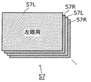
デジタルテレビ30が備える映像信号処理装置100によって生成された出力三次元映像信号57の一例を図2Aに示す。なお、図2Aは、実施の形態1に係る三次元映像信号の配置パターンの一例を示す図である。
An example of the output
図2Aに示す出力三次元映像信号57は、左眼用画像57Lと右眼用画像57Rとを1フレーム毎に交互に含んでいる。例えば、出力三次元映像信号57のフレームレートは120fpsであり、走査方式はプログレッシブ方式である。なお、このような映像信号を120pの映像信号とも記載する。
The output
表示パネル34は、図2Aに示す出力三次元映像信号57を受け取り、1フレーム毎に左眼用画像57Lと右眼用画像57Rとを交互に表示する。このとき、トランスミッタ35は、表示パネル34が左眼用画像57Lを表示している期間に、シャッタメガネ40の左眼用液晶シャッタを開き、かつ、右眼用液晶シャッタを閉じるようにシャッタメガネ40を制御する。また、トランスミッタ35は、表示パネル34が右眼用画像57Rを表示している期間に、シャッタメガネ40の右眼用液晶シャッタを開き、かつ、左眼用液晶シャッタを閉じるようにシャッタメガネ40を制御する。これにより、視聴者の左眼には左眼用画像57Lが、右眼には右眼用画像57Rがそれぞれ選択的に入射される。
The
このように、表示パネル34は、左眼用画像57Lと右眼用画像57Rとを時間的に切り替えて表示する。なお、図2Aに示す例では、1フレーム毎に左眼用画像57Lと右眼用画像57Rとを切り替えたが、複数フレーム毎に切り替えてもよい。
In this manner, the
なお、視聴者の左眼と右眼とにそれぞれ選択的に左眼用画像と右眼用画像とを入射させる方法は、上記の方法に限らず、他の方法を用いてもよい。 Note that the method of selectively causing the left eye image and the right eye image to enter the viewer's left eye and right eye, respectively, is not limited to the above method, and other methods may be used.
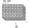
例えば、デジタルテレビ30が備える映像信号処理装置100は、図2Bに示すような出力三次元映像信号58を生成してもよい。生成した出力三次元映像信号58は、表示パネル34に出力される。なお、図2Bは、実施の形態1に係る三次元映像信号の配置パターンの一例を示す図である。
For example, the video
例えば、図2Bに示す出力三次元映像信号58は、左眼用画像58Lと右眼用画像58Rとを、1フレーム内の異なる領域に含んでいる。具体的には、左眼用画像58Lと右眼用画像58Rとが市松状に配置されている。例えば、出力三次元映像信号58のフレームレートは60fpsであり、走査方式はプログレッシブ方式である。なお、このような映像信号を60pの映像信号とも記載する。
For example, the output
表示パネル34は、図2Bに示す出力三次元映像信号58を受け取り、左眼用画像58Lと右眼用画像58Rとが市松状に配置された画像を表示する。この場合、表示パネル34は、左眼用画像58Lが表示される画素上に形成された左眼用偏光フィルムと、右眼用画像58Rが表示される画素上に形成された右眼用偏光フィルムとを備える。これにより、左眼用画像58Lと右眼用画像58Rとに互いに異なる偏光(直線偏光又は円偏光など)をかける。
The
さらに、視聴者は、シャッタメガネ40の代わりに、表示パネル34が備える偏光にそれぞれ対応する左眼用偏光フィルタと右眼用偏光フィルタとを備える偏光メガネを装着する。これにより、視聴者の左眼及び右眼にそれぞれ、左眼用画像58Lと右眼用画像58Rとを選択的に入射させることができる。
Further, the viewer wears polarized glasses including a left-eye polarizing filter and a right-eye polarizing filter corresponding to the polarized light included in the
このように、表示パネル34は、左眼用画像58Lと右眼用画像58Rとが1フレーム内に空間的に異なる領域に配置された映像を表示する。なお、図2Bに示す例では、1画素毎に左眼用画像58Lと右眼用画像58Rとを配置したが、複数の画素毎に左眼用画像58Lと右眼用画像58Rとを配置してもよい。また、市松状でなくてもよく、水平ライン毎、又は、垂直ライン毎に左眼用画像58Lと右眼用画像58Rとを配置してもよい。
As described above, the
以下では、実施の形態1に係る映像信号処理装置100の詳細な構成及び動作について説明する。
Hereinafter, a detailed configuration and operation of the video
実施の形態1に係る映像信号処理装置100は、左眼用画像と右眼用画像とを含む三次元映像信号を処理する。具体的には、映像信号処理装置100は、入力された三次元映像信号にフォーマット変換処理を行う。例えば、デジタルビデオレコーダ20が備える映像信号処理装置100は、第1フォーマットの入力三次元映像信号52を第2フォーマットの出力三次元映像信号53に変換する。
The video
ここで、映像信号処理装置100が行うフォーマット変換処理とは、配置パターン、フレームレート、走査方式、及び画像サイズの変換の少なくとも1つの処理である。なお、映像信号処理装置100は、これら以外の処理を行ってもよい。
Here, the format conversion process performed by the video
配置パターンの変換は、三次元映像信号に含まれる左眼用画像と右眼用画像との時間的な配置又は空間的な配置を変換することである。例えば、映像信号処理装置100は、図2Aに示す三次元映像信号を図2Bに示す三次元映像信号に変換する。
The conversion of the arrangement pattern is to convert a temporal arrangement or a spatial arrangement of the left eye image and the right eye image included in the 3D video signal. For example, the video
フレームレートの変換は、三次元映像信号のフレームレートを変換することである。例えば、映像信号処理装置100は、フレーム補間、又はフレームのコピー処理を行うことで、低フレームレート(例えば、60fps)の三次元映像信号を高フレームレート(例えば、120fps)の三次元映像信号に変換する。あるいは、映像信号処理装置100は、フレームを間引くことで、又は、複数のフレームを時間的に平均化したフレームを生成することで、高フレームレートの三次元映像信号を低フレームレートの三次元映像信号に変換する。
The conversion of the frame rate is to convert the frame rate of the 3D video signal. For example, the video
走査方式の変換は、インターレース方式からプログレッシブ方式への変換、又は、プログレッシブ方式からインターレース方式への変換である。なお、インターレース方式とは、奇数番目のラインから構成されるトップフィールドと偶数番目のラインから構成されるボトムフィールドとにフレームを分けて走査する方式である。 The scanning method conversion is conversion from the interlace method to the progressive method, or conversion from the progressive method to the interlace method. Note that the interlace method is a method in which a frame is divided into a top field composed of odd-numbered lines and a bottom field composed of even-numbered lines.
画像サイズの変換は、画像の拡大及び縮小を行うことである。例えば、映像信号処理装置100は、画素の補間又はコピーを行うことで画像を拡大する。あるいは、映像信号処理装置100は、画素を間引くことで、又は、複数の画素の平均値を算出することで画像を縮小する。例えば、画像サイズには、VGA(640×480)、ハイビジョン画像(1280×720)、及びフルハイビジョン画像(1920×1080)などがある。
The conversion of the image size is to enlarge and reduce the image. For example, the video
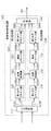
図3は、実施の形態1に係る映像信号処理装置100の構成を示すブロック図である。
FIG. 3 is a block diagram showing a configuration of video
図3に示す映像信号処理装置100は、入力選択部110と、第1処理部120と、第2処理部130と、合成部140とを備える。
The video
入力選択部110は、入力三次元映像信号を左眼用画像210Lと右眼用画像210Rとに分割し、左眼用画像210Lを第1処理部120へ出力し、右眼用画像210Rを第2処理部130へ出力する。具体的には、入力選択部110は、入力三次元映像信号を、左眼用画像と右眼用画像とのうち左眼用画像のみを含む左眼用映像データと、右眼用画像のみを含む右眼用映像データとに分割する。そして、入力選択部110は、左眼用映像データを第1処理部120へ出力し、右眼用映像データを第2処理部130へ出力する。なお、入力選択部110は、入力三次元映像信号を第1処理部120と第2処理部130とへそれぞれ出力し、第1処理部120が左眼用映像データを抽出し、第2処理部130が右眼用映像データを抽出してもよい。
The
第1処理部120は、入力選択部110から入力された左眼用映像データを処理する。具体的には、第1処理部120は、左眼用映像データのフォーマット変換を行う。このとき、第1処理部120は、左眼用映像データから、所定の処理を行う際に用いられる情報を取得し、取得した情報を第2処理部130へ出力する。例えば、第1処理部120は、入力された左眼用映像データに画像特徴検出処理を行うことで、特徴検出結果として所定の情報を取得する。画像特徴検出処理は、例えば、フィルム検出である。フィルム検出の詳細は後で説明する。
The
第2処理部130は、入力選択部110から入力された右眼用映像データを処理する。具体的には、第2処理部130は、右眼用映像データのフォーマット変換を行う。このとき、第2処理部130は、第1処理部120によって左眼用映像データから取得された情報を受け取る。そして、第2処理部130は、受け取った情報を利用して、右眼用映像データに所定の処理を行う。
The
合成部140は、第1処理部120によって生成された変換後の左眼用画像250Lと、第2処理部130によって生成された変換後の右眼用画像250Rとを合成することにより、合成画像260を生成する。生成された合成画像260を含む映像信号は、出力三次元映像信号として出力される。
The combining
第1処理部120の詳細な構成は、以下の通りである。
The detailed configuration of the
図3に示すように、第1処理部120は、第1水平リサイズ部121と、変換処理部122と、垂直リサイズ部123と、第2水平リサイズ部124とを備える。
As shown in FIG. 3, the
第1水平リサイズ部121は、入力された左眼用画像210Lの水平方向の画像サイズをリサイズ、すなわち、拡大又は縮小する。例えば、第1水平リサイズ部121は、画素を間引くことで、又は、複数の画素の平均値を算出することで、左眼用画像210Lを水平方向に縮小する。縮小後の左眼用画像220Lは、変換処理部122に出力される。
The first
変換処理部122は、入力された縮小後の左眼用画像220LにIP変換を行う。IP変換は、走査方式の変換の一例であり、縮小後の左眼用画像220Lの走査方式を、インターレース方式からプログレッシブ方式へ変換することである。IP変換後の左眼用画像230Lは、垂直リサイズ部123に出力される。
The
なお、変換処理部122は、所定の処理に用いられる情報を左眼用画像220Lから取得し、第2処理部130へ出力する。また、変換処理部122は、ノイズリダクション処理(NR処理)を行ってもよい。変換処理部122の詳細な構成及び動作については、後で図4を用いて説明する。また、上記の所定の処理及び当該処理に用いられる情報についても、後で説明する。
Note that the
垂直リサイズ部123は、変換処理部122によってIP変換された左眼用画像230Lの垂直方向の画像サイズをリサイズ、すなわち、拡大又は縮小する。リサイズ後の左眼用画像240Lは、第2水平リサイズ部124に出力される。
The
第2水平リサイズ部124は、リサイズ後の左眼用画像240Lの水平方向の画像サイズをリサイズ、すなわち、拡大又は縮小する。例えば、第2水平リサイズ部124は、画素を補間することで、又は、画素をコピーすることでリサイズ後の左眼用画像240Lを水平方向に拡大する。拡大後の左眼用画像250Lは、合成部140に出力される。
The second
また、第2処理部130の詳細な構成は、以下の通りである。
The detailed configuration of the
図3に示すように、第2処理部130は、第1水平リサイズ部131と、変換処理部132と、垂直リサイズ部133と、第2水平リサイズ部134とを備える。
As shown in FIG. 3, the
第1水平リサイズ部131は、入力された右眼用画像210Rの水平方向の画像サイズをリサイズ、すなわち、拡大又は縮小する。例えば、第1水平リサイズ部131は、画素を間引くことで、又は、複数の画素の平均値を算出することで、右眼用画像210Rを水平方向に縮小する。縮小後の右眼用画像220Rは、変換処理部132に出力される。
The first
変換処理部132は、入力された縮小後の右眼用画像220RにIP変換を行う。IP変換は、縮小後の右眼用画像220Rの走査方式を、インターレース方式からプログレッシブ方式へ変換することである。IP変換後の右眼用画像230Rは、垂直リサイズ部133に出力される。
The
なお、変換処理部132は、第1処理部120の変換処理部122から所定の処理に用いられる情報を取得する。また、変換処理部132は、ノイズリダクション処理(NR処理)を行ってもよい。
The
垂直リサイズ部133は、変換処理部132によってIP変換された右眼用画像230Rの垂直方向の画像サイズをリサイズ、すなわち、拡大又は縮小する。リサイズ後の右眼用画像240Rは、第2水平リサイズ部134に出力される。
The
第2水平リサイズ部134は、リサイズ後の右眼用画像240Rの水平方向の画像サイズをリサイズ、すなわち、拡大又は縮小する。例えば、第2水平リサイズ部134は、画素を補間することで、又は、画素をコピーすることでリサイズ後の右眼用画像240Rを水平方向に拡大する。拡大後の右眼用画像250Rは、合成部140に出力される。
The second horizontal resizing unit 134 resizes, that is, enlarges or reduces the horizontal image size of the resized right-
なお、入力選択部110は、左眼用画像210Lを第2処理部130へ出力し、右眼用画像210Rを第1処理部120へ出力してもよい。また、入力三次元映像信号として、左眼用画像のみを示す左眼用映像信号と右眼用画像のみを示す右眼用映像信号との2つの映像信号が入力された場合は、入力選択部110は、分割処理を行うことなく、左眼用映像信号を第1処理部120へ出力し、右眼用映像信号を第2処理部130へ出力してもよい。
Note that the
以上のように、実施の形態1に係る映像信号処理装置100は、左眼用画像及び右眼用画像のいずれか一方から情報を取得し、取得した情報を用いて左眼用画像及び右眼用画像の両方を処理する。
As described above, the video
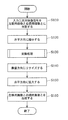
続いて、上記の映像信号処理装置100が行う処理について、図4及び図5を用いて説明する。なお、図4は、実施の形態1に係る映像信号処理装置100の動作の一例を示すフローチャートである。図5は、実施の形態1に係る映像信号処理装置100による三次元映像信号の流れの一例を示す図である。
Next, processing performed by the video
以下では、デジタルビデオレコーダ20が備える映像信号処理装置100の動作について説明する。なお、デジタルテレビ30が備える映像信号処理装置100の動作についても同様である。
Below, operation | movement of the video
まず、入力選択部110は、入力三次元映像信号52を左眼用画像210Lと右眼用画像210Rとに分割する(S110)。なお、実施の形態1に係る入力三次元映像信号52は、インターレース方式の映像信号であり、例えば、フルハイビジョンの映像である。
First, the
したがって、図5に示すように、左眼用画像210Lは、左眼用トップフィールド210Ltと左眼用ボトムフィールド210Lbとを含んでいる。同様に、右眼用画像210Rは、右眼用トップフィールド210Rtと右眼用ボトムフィールド210Rbとを含んでいる。各フィールドは、1920×540画素で構成される。
Therefore, as shown in FIG. 5, the left-
次に、第1水平リサイズ部121及び131はそれぞれ、左眼用画像210L及び右眼用画像210Rを水平方向に縮小する(S120)。ここでは、第1水平リサイズ部121及び131は、水平方向に1/2倍に縮小する。これにより、図5に示すように、縮小後の左眼用画像220Lと縮小後の右眼用画像220Rとを生成する。なお、縮小率は1/2倍に限られない。なお、第1水平リサイズ部121及び131はそれぞれ、左眼用画像210L及び右眼用画像210Rを水平方向に拡大してもよい。
Next, the first
縮小後の左眼用画像220Lは、縮小後の左眼用トップフィールド220Ltと縮小後の左眼用ボトムフィールド220Lbとを含んでいる。縮小後の右眼用画像220Rは、縮小後の右眼用トップフィールド220Rtと縮小後の右眼用ボトムフィールド220Rbとを含んでいる。各フィールドは、960×540画素で構成される。
The reduced left-
なお、このとき、第1水平リサイズ部121及び131は、図2Bに示すような市松状の画像を生成するために、それぞれ開始位置をずらしてもよい。具体的には、第1水平リサイズ部121は、左眼用トップフィールド210Ltに含まれる偶数番目の画素(0,2,4,6…)を抽出することで、縮小後の左眼用トップフィールド220Ltを生成する。さらに、第1水平リサイズ部121は、左眼用ボトムフィールド210Lbに含まれる奇数番目の画素(1,3,5,7…)を抽出することで、縮小後の左眼用ボトムフィールド220Lbを生成する。
At this time, the first
また、第1水平リサイズ部131は、右眼用トップフィールド210Rtに含まれる奇数番目の画素(1,3,5,7…)を抽出することで、縮小後の右眼用トップフィールド220Rtを生成する。さらに、第1水平リサイズ部131は、右眼用ボトムフィールド210Rbに含まれる偶数番目の画素(0,2,4,6…)を抽出することで、縮小後の右眼用ボトムフィールド220Rbを生成する。
Further, the first
次に、変換処理部122及び変換処理部132はそれぞれ、縮小後の左眼用画像220Lと縮小後の右眼用画像220RとにIP変換を行う(S130)。変換処理部122及び変換処理部132はそれぞれ、IP変換を行うことで、プログレッシブ方式の左眼用画像230Lと右眼用画像230Rとを生成する。なお、IP変換の詳細については、後で説明する。
Next, the
次に、垂直リサイズ部123及び133は、左眼用画像230Lと右眼用画像230Rとを垂直方向にリサイズ、すなわち、拡大又は縮小する(S140)。図5に示す例では、垂直リサイズ部123及び133は、垂直方向のリサイズを行わずに、左眼用画像240Lと右眼用画像240Rとを出力する。
Next, the
次に、第2水平リサイズ部124及び134は、左眼用画像240Lと右眼用画像240Rとを水平方向に拡大する(S150)。例えば、第2水平リサイズ部124は、左眼用画像240Lに含まれる各画素をコピーすることで、2倍に拡大された左眼用画像250Lを生成する。同様に、第2水平リサイズ部134は、右眼用画像240Rに含まれる各画素をコピーすることで、2倍に拡大された右眼用画像250Rを生成する。
Next, the second horizontal resizing
なお、拡大率は、例えば、第1水平リサイズ部121及び131における縮小処理の縮小率の逆数である。ただし、これには限られない。第2水平リサイズ部124及び134はそれぞれ、左眼用画像240Lと右眼用画像240Rとを水平方向に縮小してもよい。
The enlargement rate is, for example, the reciprocal of the reduction rate of the reduction process in the first
最後に、合成部140は、左眼用画像250Lと右眼用画像250Rとを合成することで、合成画像260を生成する(S160)。合成画像260は、例えば、図2Bに示すように、左眼用画像250Lに含まれる画素と右眼用画像250Rに含まれる画素とが市松状に配列された画像である。合成により得られた合成画像260は、出力三次元映像信号53として出力される。
Finally, the synthesizing
以上のようにして、実施の形態1に係る映像信号処理装置100は、入力三次元映像信号52を処理することで、出力三次元映像信号53を生成する。
As described above, the video
次に、変換処理部122の詳細な構成及びその動作と、左眼用画像から取得する情報、及び当該情報を用いた所定の処理とについて説明する。
Next, a detailed configuration and operation of the
実施の形態1に係る変換処理部122は、IP変換を行う前にフィルム検出を行う。フィルム検出は、画像特徴検出処理の一例であり、映像データがフィルム映像から生成された映像データであるか否かを検出する処理である。ここでは、変換処理部122は、フィルム検出として、左眼用画像のみを含む左眼用映像データがフィルム映像から生成された映像データであるか否かを検出する。
The
そして、変換処理部122は、フィルム検出の結果を変換処理部132に出力する。なお、変換処理部132では、右眼用画像のみを含む右眼用映像データにIP変換を行う。以下では、変換処理部122の具体的な構成及び動作について説明する。
Then, the
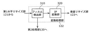
図6は、実施の形態1に係る変換処理部122の構成の一例を示すブロック図である。図6に示すように、変換処理部122は、フィルム検出部310と、IP変換部320とを備える。
FIG. 6 is a block diagram illustrating an example of the configuration of the
フィルム検出部310は、本発明に係る情報取得部の一例であり、左眼用画像にフィルム検出を行う。具体的には、フィルム検出部310は、左眼用画像を含む左眼用映像データにフィルム検出を行うことで、入力三次元映像信号がフィルム映像から生成された映像信号であるか否かを示すフィルム情報と、入力三次元映像信号がフィルム映像から生成された映像信号である場合に、フィルム映像に含まれる複数のフレームのうちの同一のフレームから生成されたピクチャを示すピクチャ情報とを取得する。なお、ここではフィルム検出部310は、ピクチャ情報の一例として、合成すべきフィールドを示すIP変換情報を取得する。
The
IP変換部320は、本発明に係る左眼用画像処理部の一例であり、フィルム情報とIP変換情報とを用いて、左眼用映像データをインターレース方式からプログレッシブ方式へ変換する。具体的には、IP変換部320は、入力三次元映像信号がフィルム映像から生成された映像信号であることをフィルム情報が示す場合に、IP変換情報を用いて左眼用映像データをインターレース方式からプログレッシブ方式へ変換する。また、入力三次元映像信号がフィルム映像から生成された映像信号ではないことをフィルム情報が示す場合、IP変換部320は、例えば、隣接する2つのフィールドを合成することで、左眼用映像データをインターレース方式からプログレッシブ方式へ変換する。
The
なお、変換処理部132は、本発明に係る右眼用画像処理部の一例であり、右眼用映像データに所定の処理を行う。具体的には、変換処理部132は、フィルム検出の結果であるフィルム情報とIP変換情報とをフィルム検出部310から受け取る。そして、変換処理部132は、IP変換部320と同様にして、フィルム情報とIP変換情報とを用いて、右眼用映像データをインターレース方式からプログレッシブ方式へ変換する。
The
図7は、実施の形態1に係る変換処理部122の動作の一例を示すフローチャートである。
FIG. 7 is a flowchart illustrating an example of the operation of the
まず、フィルム検出部310は、左眼用映像データにフィルム検出を行う(S131)。なお、第1処理部120に右眼用映像データを入力することで、フィルム検出部310は、右眼用映像データにフィルム検出を行ってもよい。フィルム検出の結果であるフィルム情報とIP変換情報とは、IP変換部320と変換処理部132とに出力される。
First, the
次に、IP変換部320及び変換処理部132は、フィルム情報とIP変換情報とを用いて、左眼用映像データ及び右眼用映像データをインターレース方式からプログレッシブ方式へ変換する(S132)。フィルム検出及びIP変換の具体的な処理については、フィルム映像と三次元映像との例を挙げて以下で説明する。
Next, the
図8は、フィルム映像と入力三次元映像信号との一例を示す図である。 FIG. 8 is a diagram illustrating an example of a film image and an input 3D image signal.
フィルム映像は、24コマ/秒(24fps)のプログレッシブ方式の映像(24pの映像)である。 The film image is a 24 frame / second (24 fps) progressive image (24p image).
入力三次元映像信号は、例えば、フレームレートが60fpsであるインターレース方式の映像(60iの映像)を示す信号である。すなわち、入力三次元映像信号は、トップフィールドとボトムフィールドとを1秒間に合わせて60枚含んでいる(トップフィールド又はボトムフィールドのみのフレームレートは、30fps)。 The input 3D video signal is a signal indicating an interlace video (60i video) having a frame rate of 60 fps, for example. That is, the input 3D video signal includes 60 top fields and bottom fields in one second (the frame rate of only the top field or the bottom field is 30 fps).
図8に示すように、24pの映像から60iの映像を生成する場合、まず、24pの映像に含まれるフレームAをトップフィールド用(Atop)、ボトムフィールド用(Abtm)、トップフィールド用(Atop)に3回読み出す。次に、24pの映像に含まれるフレームBをボトムフィールド用(Bbtm)、トップフィールド用(Btop)に2回読み出す。次に、24pの映像に含まれるフレームCをボトムフィールド用(Cbtm)、トップフィールド用(Ctop)、ボトムフィールド用(Cbtm)に3回読み出す。 As shown in FIG. 8, when a 60i video is generated from a 24p video, first, a frame A included in the 24p video is used for a top field (A top ), a bottom field (A btm ), and a top field ( A top ) is read three times. Next, the frame B included in the 24p video is read twice for the bottom field (B btm ) and the top field (B top ). Next, the frame C included in the 24p video is read out three times for the bottom field (C btm ), the top field (C top ), and the bottom field (C btm ).
以上のように、フレームの3回読み出しと2回読み出しとを交互に繰り返すことで、24pの映像から60iの映像を生成することができる(3−2プルダウン処理)。なお、他のフレームレート間での変換を行う場合も同様に、変換前のフレームレートと変換後のフレームレートとの割合に応じて、読み出し回数を決定すればよい。 As described above, a 60i video can be generated from a 24p video by alternately repeating the reading of the frame three times and the reading of the frame twice (3-2 pull-down processing). Similarly, when converting between other frame rates, the number of readings may be determined according to the ratio between the frame rate before conversion and the frame rate after conversion.
次に、図8に示すように生成された60iの映像(入力三次元映像信号)を60pの映像(出力三次元映像信号)にIP変換する場合について説明する。なお、60pの映像は、60fpsのプログレッシブ方式の映像のことである。 Next, a case where the 60i video (input 3D video signal) generated as shown in FIG. 8 is IP converted into a 60p video (output 3D video signal) will be described. The 60p video is a 60 fps progressive video.
フィルム検出部310は、フィルム検出として、2つのフィールド間の差分を算出する。例えば、フィルム検出部310は、対象となるフィールドと2つ前のフィールドとの差分を算出する。図8に示すように24pの映像であるフィルム映像から生成された60iの映像を含む入力三次元映像信号は、5枚のフィールド中に2枚の同じフィールドが含まれる(例えば、1番目と3番目のAtop、6番目と8番目のCbtm)。
The
したがって、2つのフィールド間の差分を順次算出すると、5枚のフィールド中に1組は、差分がほぼ0となるフィールドの組が存在する。これにより、フィルム検出部310は、差分がほぼ0となる割合を検出することで、入力三次元映像信号が3−2プルダウンされた映像を含んでいることを検出することができる。つまり、差分がほぼ0となる割合が5枚のフィールド中に1組のフィールドであると検出した場合、フィルム検出部310は、入力三次元映像信号がフィルム映像から生成された映像信号であることを示すフィルム情報をIP変換部320へ出力する。
Therefore, when the difference between the two fields is sequentially calculated, one set of five fields includes a field set in which the difference is almost zero. Thereby, the
さらに、フィルム検出部310は、差分がほぼ0となる割合が5枚のフィールド中に1組のフィールドであると検出した場合、フィルム映像のフレームレートを示すフレームレート情報を取得する。つまり、入力三次元映像信号が3−2プルダウンされた映像であり、かつ、入力三次元映像信号のフレームレートが60fpsであることから、フィルム映像のフレームレートは、24(=60×2/5)fpsであることが分かる。そして、フィルム検出部310は、IP変換の際に、合成すべきトップフィールドとボトムフィールドとを示すIP変換情報をIP変換部320へ出力する。
Further, when the
図9は、実施の形態1に係るIP変換部320による、60iの映像を60pの映像にIP変換する際の処理例を示す図である。
FIG. 9 is a diagram illustrating a processing example when the
IP変換部320は、60iの入力映像と、当該入力映像を1フレーム遅延した第1遅延映像と、60iの入力映像を2フレーム遅延した第2遅延映像との中から、フィールド毎に2つの映像を選択して合成する。このとき、どの映像を選択するか、すなわち、どのトップフィールドとどのボトムフィールドとを選択するかは、フィルム検出部310によるフィルム検出の結果であるIP変換情報に従って決定される。
The
具体的には、フィルム検出部310は、入力三次元映像信号が3−2プルダウンされた映像信号であることを検出した場合、フィルム映像に含まれる同一のフレームから生成されたフィールドを示す情報をIP変換情報として出力する。そして、IP変換部320は、受け取ったIP変換情報に従って、同一のフレームから生成されたフィールド同士を選択して合成する。
Specifically, when the
例えば、IP変換部320は、図9に点線で示す四角によって囲まれた2枚のフィールドを合成することで1フレームの画像を生成する。
For example, the
具体的には、IP変換部320は、時刻T2では、第1遅延映像のAtopと60iの映像のAbtmとを合成する。また、時刻T3では、IP変換部320は、第1遅延映像のAbtmと60iの映像のAtopとを合成する。なお、時刻T3では、第1遅延映像のAbtmと第2遅延映像のAtopとを合成してもよい。
Specifically, the
さらに、時刻T4では、IP変換部320は、第1遅延映像のAtopと第2遅延映像のAbtmとを合成する。次に、時刻T5では、IP変換部320は、60iの映像のBtopと第1遅延映像のAbtmとを合成する。
Further, at time T4, the
このように、3−2プルダウンされた映像信号をIP変換する場合、同一のフレームから生成された3枚連続するフィールドについては、最初の2枚は、第1遅延映像と入力映像とを合成し、残りの1枚は第1遅延映像と第2遅延映像とを合成すればよい。なお、真ん中の1枚は、第1遅延映像と第2遅延映像とを合成してもよい。さらに、同一のフレームから生成された2枚連続するフィールドについては、1枚目は、第1遅延映像と入力映像とを合成し、2枚目は、第1遅延映像と第2遅延映像とを合成すればよい。 As described above, when IP conversion is performed on a video signal that has been pulled down 3-2, for the three consecutive fields generated from the same frame, the first two images are combined with the first delayed video and the input video. The remaining one image may be synthesized with the first delayed video and the second delayed video. Note that the middle one may combine the first delayed video and the second delayed video. Further, for two consecutive fields generated from the same frame, the first frame combines the first delayed video and the input video, and the second frame combines the first delayed video and the second delayed video. What is necessary is just to synthesize.
以上のように、IP変換部320は、フィルム映像に含まれる同一のフレームから生成されたフィールド同士を選択して合成することで、所定のフレームレートのインターレース方式の入力三次元映像信号から同じフレームレートのプログレッシブ方式の出力三次元映像信号を生成する。
As described above, the
また、IP変換部320は、入力三次元映像信号がフィルム映像から生成された映像信号ではないことをフィルム情報が示す場合は、隣接するフィールドを順に合成することでプログレッシブ方式の出力三次元映像信号を生成する。
In addition, when the film information indicates that the input 3D video signal is not a video signal generated from the film video, the
なお、入力三次元映像信号がフィルム映像から生成された映像信号である場合に、IP変換部320がフィルム検出を行わず、単に、隣接するフィールドを順に合成した場合、例えば、AtopとBbtmとが合成されてしまうことになり、画質が劣化してしまう。したがって、上記のようにフィルム検出を行うことで、本実施の形態に係るIP変換部320は、フィルム映像に含まれる同一のフレームから生成されたフィールド同士を合成することができるので、画質の劣化を防止することができる。
When the input 3D video signal is a video signal generated from a film video, the
以上のように、実施の形態1に係る変換処理部122では、左眼用映像データにフィルム検出を行い、その結果を変換処理部132に出力する。変換処理部132は、変換処理部122から入力されるフィルム検出の結果を用いて、右眼用映像データにIP変換を行う。
As described above, the
左眼用画像と右眼用画像とは、そもそも同じ被写体を異なる視点から撮影して得られた画像、又は、同じ画像を所定の視差の分だけずらして生成された画像である。したがって、左眼用映像データと右眼用映像データとのいずれにフィルム検出を行ったとしても、同じ結果が得られる。 The left-eye image and the right-eye image are originally images obtained by photographing the same subject from different viewpoints, or images generated by shifting the same image by a predetermined amount of parallax. Therefore, the same result can be obtained regardless of whether film detection is performed on either the left-eye video data or the right-eye video data.
このため、本実施の形態のように、左眼用映像データ及び右眼用映像データのいずれか一方のみにフィルム検出を行い、その検出結果を左眼用映像データ及び右眼用映像データの双方に利用することで、処理の重複を避けることができる。これにより、本実施の形態に係る映像信号処理装置100は、冗長な処理を避けることができ、消費電力を低減、及び処理速度を向上させることができる。
For this reason, as in the present embodiment, film detection is performed on only one of the left-eye video data and the right-eye video data, and the detection result is obtained for both the left-eye video data and the right-eye video data. By using it, you can avoid duplication of processing. Thus, video
また、左眼用映像データと右眼用映像データとで個別に検出を行った場合、互いに異なる検出結果が得られる可能性がある。この場合、変換処理部122及び132は、異なる検出結果に基づいてIP変換を行うことになるので、合成部140が左眼用画像と右眼用画像とを合成した場合に不自然な映像が生成される可能性がある。
Further, when detection is separately performed for the left-eye video data and the right-eye video data, different detection results may be obtained. In this case, since the
これに対して、本実施の形態に係る映像信号処理装置100では、同じ検出結果を用いて、左眼用映像データと右眼用映像データとの両方を処理するので、上記のように不自然な映像が生成される可能性を低減することができる。
On the other hand, since the video
なお、上記説明では、インターレース方式の入力三次元映像信号にフィルム検出を行う構成について示したが、プログレッシブ方式の入力三次元映像信号にフィルム検出を行ってもよい。例えば、図8に示すような24pのフィルム映像(ABC…)から生成された、図9に示すような60pの映像信号(AAABBCCC…)が、入力三次元映像信号として本実施の形態に係る映像信号処理装置100に入力された場合を想定する。
In the above description, the film detection is performed on the interlaced input 3D video signal. However, the film detection may be performed on the progressive input 3D video signal. For example, a 60p video signal (AAABBCCC ...) as shown in FIG. 9 generated from a 24p film video (ABC ...) as shown in FIG. 8 is used as an input 3D video signal according to the present embodiment. Assume that the signal is input to the
フィルム検出部310は、左眼用映像データに含まれる2つのフレーム間の差分を算出する。例えば、フィルム検出部310は、時間的に隣接する2つのフレーム間の差分を算出することで、差分が“小小大小大小小大小大…”となる。これにより、フィルム検出部310は、入力三次元映像信号が3−2プルダウンされた映像を含んでいることを示すフィルム情報をIP変換部320へ出力する。
The
さらに、フィルム検出部310は、ピクチャ情報の一例として、フィルム映像に含まれる同一のフレームから生成されたフレームを示すフレーム情報を、IP変換部320と変換処理部132とへ出力する。例えば、時間的に隣接する2つのフレーム間の差分がほぼ0となった場合、フィルム検出部310は、これら2つのフレームが、フィルム映像に含まれる同一のフレームから生成されたフレームであると判定することで、フレーム情報を出力する。
Furthermore, the
IP変換部320は、フィルム情報とフレーム情報とを受け取り、受け取ったフィルム情報とフレーム情報とに基づいて、左眼用映像データである入力三次元映像信号のフレームレートを変換する。例えば、入力三次元映像信号が3−2プルダウンされた映像を含んでいることをフィルム情報が示す場合、IP変換部320は、フレーム情報を用いて出力すべきフレームとその枚数とを決定する。
The
例えば、IP変換部320は、同一のフレームを2枚ずつ選択して出力することで、フレームレートが48fpsの映像信号(AABBCC…)を出力する。この映像信号には、同一のフレームが2枚ずつ含まれる。あるいは、IP変換部320は、同一のフレームを5枚ずつ選択して出力することで、フレームレートが120fpsの映像信号(AAAAABBBBBCCCCC…)を出力してもよい。この映像信号には、同一のフレームが5枚ずつ含まれる。
For example, the
変換処理部132は、右眼用映像データにIP変換部320と同様の処理を行う。
The
以上のようにして、プログレッシブ方式の入力三次元映像信号にフィルム検出を行ってもよい。この場合も、左眼用映像データと右眼用映像データとでは、フィルム検出結果が一致するので、一方のみにフィルム検出を行うことで、処理量の増大を抑制することができる。 As described above, film detection may be performed on a progressive input 3D video signal. Also in this case, since the film detection results match between the left-eye video data and the right-eye video data, an increase in processing amount can be suppressed by performing film detection on only one side.
なお、IP変換部320は、走査方式の変換とフレームレートの変換との両方を行ってもよい。例えば、IP変換部320は、インターレース方式の映像信号(60iの映像信号)をプログレッシブ方式の映像信号(60pの映像信号)に変換するとともに、変換した映像信号のフレームレートを上述のように変換する。これにより、例えば、IP変換部320は、60iの映像信号から48p又は120pの映像信号を生成することができる。
Note that the
また、フィルム検出では、入力三次元映像信号として3−2プルダウンされた映像信号について説明したが、2−2プルダウンされた映像信号であってもよい。例えば、隣接する2フィールドの差分を算出すると、2−2プルダウンされた映像信号の場合、差分が“大小大小…”を繰り返す。したがって、フィルム検出部310は、検出した差分の変化の傾向を判断することで、入力三次元映像信号が2−2プルダウンされた映像信号であることを検出することができる。
Further, in the film detection, the video signal pulled down 3-2 as the input 3D video signal has been described, but the video signal pulled down 2-2 may be used. For example, when the difference between two adjacent fields is calculated, the difference repeats “large, small, large, small ...” in the case of a video signal pulled down 2-2. Therefore, the
なお、フィルム検出部310が行うフィルム検出は、上記の方法に限られず、他の方法であってもよい。
The film detection performed by the
また、本実施の形態に係る映像信号処理装置100は、第1処理部120と第2処理部130とを用いて、左眼用映像データと右眼用映像データとを並列処理する構成について説明したが、2つの処理部のうちいずれか1つの処理部のみを備えていてもよい。例えば、入力選択部110は、左眼用映像データと右眼用映像データとの両方を第1処理部120に入力してもよい。
Also, the video
第1処理部120が備える各処理部は、左眼用映像データと右眼用映像データとをそれぞれシーケンシャルに処理する。例えば、左眼用映像データを処理した後で、右眼用映像データを処理する(あるいは、逆でもよい)。このとき、左眼用映像データから取得されたフィルム情報及びIP変換情報は、メモリなどに格納しておけばよい。
Each processing unit included in the
また、本実施の形態では、左眼用画像にフィルム検出を行ったが、右眼用画像にフィルム検出を行い、検出結果を左眼用画像と右眼用画像との両方に利用してもよい。 In this embodiment, film detection is performed on the left-eye image, but film detection is performed on the right-eye image, and the detection result may be used for both the left-eye image and the right-eye image. Good.
以上のように、実施の形態1に係る映像信号処理装置100は、左眼用画像及び右眼用画像の一方から、IP変換などの所定の処理を行う際に用いられる情報を取得する情報取得部の一例であるフィルム検出部310を備える。また、映像信号処理装置100は、情報取得部の一例であるフィルム検出部310によって取得された情報を用いて、左眼用画像及び右眼用画像の両方に、IP変換又はフレームレートの変換を行う画像処理部の一例であるIP変換部320及び変換処理部132を備える。
As described above, the video
この構成により、実施の形態1に係る映像信号処理装置100によれば、上記情報を取得するための処理の一例であるフィルム検出を左眼用画像及び右眼用画像の一方のみに行えばよく、処理の重複を避けることができる。したがって、処理量の増大を抑制することができる。
With this configuration, according to the video
(実施の形態2)
実施の形態2に係る映像信号処理装置は、実施の形態1と同様に、左眼用画像及び右眼用画像の一方から、所定の処理を行う際に用いられる情報を取得する情報取得部と、情報取得部によって取得された情報を用いて、前記左眼用画像及び前記右眼用画像の両方に前記処理を行う画像処理部とを備えることを特徴とする。より具体的には、実施の形態2では、情報取得部は、左眼用画像及び右眼用画像の一方に、輝度値が一定の特定画像が含まれているか否かを検出することで、特定画像が含まれている領域を示す特定画像情報を取得する。
(Embodiment 2)
As in the first embodiment, the video signal processing apparatus according to the second embodiment includes an information acquisition unit that acquires information used when performing predetermined processing from one of the left-eye image and the right-eye image. And an image processing unit that performs the processing on both the left-eye image and the right-eye image using the information acquired by the information acquisition unit. More specifically, in the second embodiment, the information acquisition unit detects whether one of the left-eye image and the right-eye image includes a specific image with a constant luminance value, Specific image information indicating an area including the specific image is acquired.
なお、以下では、実施の形態1と重複する説明は省略し、実施の形態1との相違点を中心に説明する。 In the following, description overlapping with that of the first embodiment will be omitted, and description will be made centering on differences from the first embodiment.
実施の形態2に係る映像信号処理装置は、実施の形態1の図3に示す映像信号処理装置100とほぼ同じであり、入力選択部110の代わりに入力選択部410を備える点が異なっている。以下では、まず、実施の形態2に係る映像信号処理装置が備える入力選択部410の構成について説明する。
The video signal processing apparatus according to the second embodiment is substantially the same as the video
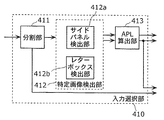
図10A及び図10Bは、実施の形態2に係る映像信号処理装置が備える入力選択部410の構成の一例を示すブロック図である。図10Aに示すように、入力選択部410は、分割部411と、特定画像検出部412と、APL算出部413及び414とを備える。
10A and 10B are block diagrams illustrating an example of the configuration of the
分割部411は、入力三次元映像信号を左眼用画像と右眼用画像とに分割する。左眼用画像は特定画像検出部412に出力され、右眼用画像はAPL算出部414に出力される。なお、左眼用画像がAPL算出部414に出力され、右眼用画像が特定画像検出部412に出力されてもよい。
The dividing
また、入力三次元映像信号が予め左眼用画像と右眼用画像とに分割されている場合は、入力選択部410は、分割部411を備えていなくてもよい。この場合は、直接、左眼用画像が特定画像検出部412に入力され、右眼用画像がAPL算出部414に入力される。
Further, when the input 3D video signal is divided in advance into a left-eye image and a right-eye image, the
特定画像検出部412は、本発明に係る情報取得部の一例であり、左眼用画像及び右眼用画像の一方に輝度値が一定の特定画像が含まれているか否かを検出することで、当該特定画像が含まれている領域を示す特定画像情報を取得する。ここでは、左眼用画像が入力されるので、特定画像検出部412は、左眼用画像に特定画像が含まれているか否かを検出する。具体的には、特定画像検出部412は、サイドパネル検出及びレターボックス検出を行う。 The specific image detection unit 412 is an example of an information acquisition unit according to the present invention, and detects whether a specific image with a constant luminance value is included in one of the left-eye image and the right-eye image. Then, specific image information indicating an area including the specific image is acquired. Here, since the image for the left eye is input, the specific image detection unit 412 detects whether or not the specific image is included in the image for the left eye. Specifically, the specific image detection unit 412 performs side panel detection and letterbox detection.
図10Aに示すように、特定画像検出部412は、サイドパネル検出部412aと、レターボックス検出部412bとを備える。
As shown in FIG. 10A, the specific image detection unit 412 includes a side
サイドパネル検出部412aは、左眼用画像及び右眼用画像の一方について、画像の左側と右側とに特定画像が含まれているか否かを検出する(サイドパネル検出又はピラーボックス検出)。ここでは、左眼用画像が入力されるので、サイドパネル検出部412aは、左眼用画像の左側と右側とに特定画像が含まれているか否かを検出する。なお、特定画像は、輝度値が一定の画像であり、例えば、黒色の画像である。
The side
サイドパネル検出部412aは、サイドパネル検出を行うことで、特定画像が含まれている領域を示す特定画像情報を取得する。特定画像情報は、例えば、特定画像が含まれている領域が、画像の左側又は右側から何画素分であるかを示す情報である。
The side
レターボックス検出部412bは、左眼用画像及び右眼用画像の一方について、画像の上側と下側とに特定画像が含まれているか否かを検出する(レターボックス検出)。ここでは、左眼用画像が入力されるので、レターボックス検出部412bは、左眼用画像の上側と下側とに特定画像が含まれているか否かを検出する。
The
レターボックス検出部412bは、レターボックス検出を行うことで、特定画像が含まれている領域を示す特定画像情報を取得する。特定画像情報は、例えば、特定画像が含まれている領域が、画像の上側又は下側から何画素分であるかを示す情報である。
The
なお、特定画像検出部412は、サイドパネル検出とレターボックス検出とのいずれか一方のみを行ってもよい。両方の検出を行った場合は、特定画像検出部412は、サイドパネル検出部412aによって取得された特定画像情報と、レターボックス検出部412bによって取得された特定画像情報とを合わせて、特定画像が含まれた領域を示す特定画像情報としてAPL算出部413及び414へ出力する。
Note that the specific image detection unit 412 may perform only one of side panel detection and letterbox detection. When both detections are performed, the specific image detection unit 412 combines the specific image information acquired by the side
APL算出部413及び414は、本発明に係る画像処理部の一例であり、左眼用画像及び右眼用画像の両方について、特定画像情報が示す領域以外の有効画像領域の平均輝度値(Average Picture Level)を算出する。具体的には、APL算出部413は、左眼用画像のうち、特定画像情報が示す領域以外の有効画像領域の平均輝度値を算出する。また、APL算出部414は、右眼用画像のうち、特定画像情報が示す領域以外の有効画像領域の平均輝度値を算出する。なお、有効画像領域は、本来の画像が表示されている領域である。
The
ここで、特定画像の例について説明する。 Here, an example of a specific image will be described.
図11Aは、サイドパネル画像500の一例を示す図である。図11Bは、レターボックス画像600の一例を示す図である。
FIG. 11A is a diagram illustrating an example of the
サイドパネル画像500は、本来の画像510の左側と右側とに特定画像520がそれぞれ付加されている。具体的には、アスペクト比が16:9の画面にアスペクト比が4:3の本来の画像510を表示させるときに、特定画像520が本来の画像510に付加される。なお、サイドパネルは、ピラーボックスともいう。
In the
サイドパネル検出部412aは、図11Aに示すような特定画像520が本来の画像510に付加されているか否かを検出する。例えば、サイドパネル検出部412aは、入力された左眼用画像の左側の領域(数画素列分の領域)と右側の領域(数画素列分の領域)との双方に含まれる画素の輝度値が全て同じ所定の値(黒色)であるか否かを判定する。
The side
左側の領域と右側の領域とに含まれる画素の輝度値が全て同じ所定の値(黒色)であると判定した場合、サイドパネル検出部412aは、入力された左眼用画像はサイドパネル画像500であると判定する。そして、サイドパネル検出部412aは、特定画像520の領域を示す特定画像情報をAPL算出部413に出力する。APL算出部413は、サイドパネル画像500のうち特定画像520を除く領域(有効画像領域)、すなわち、本来の画像510の平均輝度値を算出する。
When it is determined that the luminance values of the pixels included in the left region and the right region are all the same predetermined value (black), the side
サイドパネル画像500の平均輝度値を算出した場合、輝度値が一定の特定画像520を含んだ平均輝度値が算出されてしまう。つまり、本来の画像510の平均輝度値とは異なる値が算出される。したがって、平均輝度値を用いて画像を補正する場合など、平均輝度値が異なっているので、正しく画像を補正することができなくなる。これに対して、本実施の形態では、サイドパネル検出を行い、特定画像の領域を特定することで、正確な補正処理などを行うことができる。
When the average luminance value of the
レターボックス画像600は、本来の画像610の上側と下側とに特定画像620がそれぞれ付加されている。具体的には、アスペクト比が4:3の画面にアスペクト比が16:9の本来の画像610を表示させるときに、特定画像620が本来の画像610に付加される。
In the
レターボックス検出部412bは、図11Bに示すような特定画像620が本来の画像610に付加されているか否かを検出する。例えば、レターボックス検出部412bは、入力された右眼用画像の上側の領域(数画素行分の領域)と下側の領域(数画素行分の領域)との双方に含まれる画素の輝度値が全て同じ所定の値(黒色)であるか否かを判定する。
The
上側の領域と下側の領域とに含まれる画素の輝度値が全て同じ所定の値(黒色)であると判定した場合、レターボックス検出部412bは、入力された右眼用画像はレターボックス画像600であると判定する。そして、レターボックス検出部412bは、特定画像520の領域を示す特定画像情報をAPL算出部413に出力する。APL算出部413は、レターボックス画像600のうち特定画像620を除く領域(有効画像領域)、すなわち、本来の画像610の平均輝度値を算出する。これにより、サイドパネル検出と同様に、レターボックス検出を行い、特定画像の領域を特定することで、正確な補正処理などを行うことができる。
When it is determined that the luminance values of the pixels included in the upper area and the lower area are all the same predetermined value (black), the
なお、上記のアスペクト比は一例であって、他のアスペクト比の場合であっても同様である。 Note that the above aspect ratio is an example, and the same applies to other aspect ratios.
以上のようにして左眼用画像から検出された特定画像情報を用いて、APL算出部414は、右眼用画像の平均輝度値を算出する。左眼用画像と右眼用画像とでは、通常、一方のみに特定画像が含まれている場合はなく、また、異なる領域に特定画像が含まれている場合もない。したがって、左眼用画像から検出された特定画像情報と、右眼用画像から検出した特定画像情報とはおおよそ一致する。
Using the specific image information detected from the left eye image as described above, the
このため、厳密な結果を必要としない場合は、左眼用画像と右眼用画像との両方から特定画像情報を取得する処理は冗長であり、本実施の形態のように、いずれか一方のみから特定画像情報を取得することで、処理量の増大を抑制することができる。なお、厳密な結果を必要とする場合は、サイドパネル検出部412a及びレターボックス検出部412bは、左眼用画像と右眼用画像とのそれぞれに、サイドパネル検出及びレターボックス検出を行えばよい。
For this reason, when exact results are not required, the process of acquiring specific image information from both the left-eye image and the right-eye image is redundant, and only one of them as in the present embodiment. By acquiring the specific image information from, an increase in the processing amount can be suppressed. In addition, when a strict result is required, the side
なお、図10Bに示すように、入力選択部410は、APL算出部414を備えていなくてもよい。つまり、APL算出部413によって、左眼用画像から算出された平均輝度値を、右眼用画像の平均輝度値として利用してもよい。なぜなら、左眼用画像の平均輝度値と右眼用画像の平均輝度値とも同じ値になることが多いためである。なお、このときのAPL算出部413は、本発明に係る情報取得部の一例である。
As illustrated in FIG. 10B, the
続いて、実施の形態2に係る映像信号処理装置の動作のうち、入力選択部410の動作について、図12を用いて説明する。なお、実施の形態2に係る映像信号処理装置の動作は、実施の形態1に係る映像信号処理装置100の動作(図4参照)とほぼ同じであり、入力選択部110の動作(S110)が異なっている。
Next, among the operations of the video signal processing apparatus according to the second embodiment, the operation of the
図12は、実施の形態2に係る映像信号処理装置が備える入力選択部410の動作の一例を示すフローチャートである。図12は、図4に示す入力選択部110の動作(S110)に相当する。
FIG. 12 is a flowchart illustrating an example of the operation of the
まず、分割部411が、入力三次元映像信号を左眼用画像と右眼用画像とに分割する(S210)。左眼用画像は、特定画像検出部412に出力され、右眼用画像はAPL算出部414に出力される。
First, the dividing
次に、特定画像検出部412は、左眼用画像にサイドパネル検出とレターボックス検出とを行う(S220)。なお、サイドパネル検出とレターボックス検出とはいずれか一方のみが実行されてもよい。例えば、サイドパネル検出により特定画像が検出された場合は、レターボックス検出を行わなくてもよい。逆に、レターボックス検出により特定画像が検出された場合は、サイドパネル検出を行わなくてもよい。検出結果である特定画像情報は、APL算出部413とAPL算出部414との両方に出力される。
Next, the specific image detection unit 412 performs side panel detection and letterbox detection on the image for the left eye (S220). Note that only one of the side panel detection and the letterbox detection may be executed. For example, when a specific image is detected by side panel detection, letterbox detection may not be performed. Conversely, when a specific image is detected by letterbox detection, side panel detection may not be performed. The specific image information that is the detection result is output to both the
次に、APL算出部413は、特定画像情報を用いて、左眼用画像の平均輝度値を算出し、APL算出部414は、特定画像情報を用いて、右眼用画像の平均輝度値を算出する(S230)。
Next, the
以上のように、実施の形態2に係る映像信号処理装置では、入力選択部410において、左眼用画像にサイドパネル検出及びレターボックス検出を行うことで、特定画像を検出し、検出した結果を用いて左眼用画像と右眼用画像との両方について、平均輝度値の算出を行う。
As described above, in the video signal processing device according to
これにより、実施の形態2に係る映像信号処理装置によれば、左眼用画像と右眼用画像とのいずれか一方のみから特定画像情報を取得することで、処理量の増大を抑制することができる。 Thereby, according to the video signal processing device according to the second embodiment, the increase in the processing amount is suppressed by acquiring the specific image information from only one of the left-eye image and the right-eye image. Can do.
なお、実施の形態2では、入力選択部410がサイドパネル検出及びレターボックス検出を行ったが、実施の形態1と同様に、これらの検出を、変換処理部122が左眼用画像に行ってもよい。そして、変換処理部122は、得られた検出結果を変換処理部132に出力してもよい。
In the second embodiment, the
また、平均輝度値の算出についても同様に、入力選択部410ではなく変換処理部122及び132が行ってもよい。あるいは、図示していない他の処理部によって実行してもよい。
Similarly, the average luminance value may be calculated by the
以上のように、本発明に係る映像信号処理装置は、左眼用画像と右眼用画像とを含む三次元映像信号処理装置であって、左眼用画像及び右眼用画像のいずれか一方から取得した情報を用いて、所定の処理を左眼用画像及び右眼用画像の両方に行う。これは、左眼用画像と右眼用画像とは通常、同じ被写体を異なる視点から撮影することにより得られた画像であって、互いに共通する点が多いことを利用する。 As described above, the video signal processing device according to the present invention is a 3D video signal processing device including a left-eye image and a right-eye image, and one of the left-eye image and the right-eye image. A predetermined process is performed on both the left-eye image and the right-eye image using the information acquired from the above. This is because the left-eye image and the right-eye image are images obtained by photographing the same subject from different viewpoints, and there are many common points.
例えば、上述のようにフィルム検出結果、サイドパネル検出結果、及びレターボックス検出結果などが、左眼用画像と右眼用画像とで共通する。したがって、共通の結果が得られる処理についてはいずれか一方にのみ行うことで、処理の重複を避けることができ、処理量の増大を抑制することができる。 For example, as described above, the film detection result, the side panel detection result, the letterbox detection result, and the like are common to the left-eye image and the right-eye image. Therefore, by performing only one of the processes for obtaining a common result, it is possible to avoid duplication of processes and to suppress an increase in the processing amount.
また、通常同じ結果が得られるはずのところ、異なる結果が得られた場合は、左眼用画像と右眼用画像とを合成する際に不自然な画像が生成されてしまう可能性がある。本発明に係る映像信号処理装置では、共通の結果を用いているため、このような不自然な画像の生成を防止することができる。 In addition, normally, the same result should be obtained, but if a different result is obtained, an unnatural image may be generated when the left-eye image and the right-eye image are combined. Since the video signal processing apparatus according to the present invention uses a common result, it is possible to prevent the generation of such an unnatural image.
以上、映像信号処理装置及び映像信号処理方法について、実施の形態に基づいて説明したが、本発明は、これらの実施の形態に限定されるものではない。本発明の趣旨を逸脱しない限り、当業者が思いつく各種変形を当該実施の形態に施したものや、異なる実施の形態における構成要素を組み合わせて構築される形態も、本発明の範囲内に含まれる。 As described above, the video signal processing apparatus and the video signal processing method have been described based on the embodiments. However, the present invention is not limited to these embodiments. Unless it deviates from the meaning of this invention, the form which carried out the various deformation | transformation which those skilled in the art can think to the said embodiment, and the form constructed | assembled combining the component in a different embodiment is also contained in the scope of the present invention. .
例えば、左眼用画像及び右眼用画像の一方にCM検出を行ってもよい。CM検出は、入力された左眼用画像又は右眼用画像が、映像に含まれる広告情報などのCMであるか、映画などのコンテンツであるかを判定する処理である。同一の表示時刻における左眼用画像と右眼用画像とのいずれか一方のみがCMであるということは通常ありえないため、CM検出結果も左眼用画像と右眼用画像とで同じである。 For example, CM detection may be performed on one of the left-eye image and the right-eye image. CM detection is processing for determining whether the input image for the left eye or the image for the right eye is a CM such as advertisement information included in the video or a content such as a movie. Since it is usually impossible that only one of the left-eye image and the right-eye image at the same display time is a CM, the CM detection result is also the same for the left-eye image and the right-eye image.
したがって、左眼用画像と右眼用画像とのいずれか一方にCM検出を行い、得られた結果を左眼用画像と右眼用画像との両方のCM検出結果として用いることができる。なお、例えば、入力選択部110又は410がCM検出を行う。例えば、画像がCMであることを示す識別子を検出する、あるいは、CMとコンテンツとで解像度の違いを検出することで、入力された左眼用画像又は右眼用画像がCMであるか否かを判定する。
Therefore, CM detection is performed on either the left eye image or the right eye image, and the obtained result can be used as the CM detection result for both the left eye image and the right eye image. For example, the
左眼用画像がCMであると判定された場合は、例えば、第1水平リサイズ部121及び131が、左眼用画像及び右眼用画像を高い縮小率で縮小することで、以降の処理量を低減することができる。
If it is determined that the image for the left eye is a CM, for example, the first
また、入力された三次元映像信号を符号化する場合に備えて、左眼用画像を含む左眼用映像データと、右眼用画像を含む右眼用映像データとの一方から動きを検出してもよい。また、同様にフレーム又はフィールドの参照関係を決定してもよい。これらの処理は、例えば、入力選択部110若しくは410、変換処理部122若しくは132、又は、他の処理部が行う。
In addition, in preparation for encoding the input 3D video signal, motion is detected from one of the left-eye video data including the left-eye image and the right-eye video data including the right-eye image. May be. Similarly, the frame or field reference relationship may be determined. These processes are performed by, for example, the
なお、本発明に係る映像信号処理装置100は、図13に示すようなデジタルビデオレコーダ20及びデジタルテレビ30に搭載される。
The video
なお、本発明を上記実施の形態に基づいて説明してきたが、本発明は、上記の実施の形態に限定されないのは言うまでもない。以下のような場合も本発明の範囲に含まれる。 Although the present invention has been described based on the above embodiment, it is needless to say that the present invention is not limited to the above embodiment. The following cases are also included in the scope of the present invention.
上記の各装置は、具体的には、マイクロプロセッサ、ROM、RAM、ハードディスクユニット、ディスプレイユニット、キーボード、マウスなどから構成されるコンピュータシステムである。RAM又はハードディスクユニットには、コンピュータプログラムが記憶されている。マイクロプロセッサが、コンピュータプログラムに従って動作することにより、各装置は、その機能を達成する。ここでコンピュータプログラムは、所定の機能を達成するために、コンピュータに対する指令を示す命令コードが複数個組み合わされて構成されたものである。 Specifically, each of the above devices is a computer system including a microprocessor, ROM, RAM, a hard disk unit, a display unit, a keyboard, a mouse, and the like. A computer program is stored in the RAM or the hard disk unit. Each device achieves its functions by the microprocessor operating according to the computer program. Here, the computer program is configured by combining a plurality of instruction codes indicating instructions for the computer in order to achieve a predetermined function.
上記の各装置を構成する構成要素の一部又は全部は、1個のシステムLSIから構成されているとしてもよい。システムLSIは、複数の構成要素を1個のチップ上に集積して製造された超多機能LSIであり、具体的には、マイクロプロセッサ、ROM、RAMなどを含んで構成されるコンピュータシステムである。RAMには、コンピュータプログラムが記憶されている。マイクロプロセッサが、コンピュータプログラムに従って動作することにより、システムLSIは、その機能を達成する。 A part or all of the constituent elements constituting each of the above-described devices may be constituted by one system LSI. The system LSI is a super multifunctional LSI manufactured by integrating a plurality of components on one chip, and specifically, a computer system including a microprocessor, a ROM, a RAM, and the like. . A computer program is stored in the RAM. The system LSI achieves its functions by the microprocessor operating according to the computer program.
上記の各装置を構成する構成要素の一部又は全部は、各装置に脱着可能なICカード又は単体のモジュールから構成されているとしてもよい。ICカード又はモジュールは、マイクロプロセッサ、ROM、RAMなどから構成されるコンピュータシステムである。ICカード又はモジュールは、上記の超多機能LSIを含むとしてもよい。マイクロプロセッサが、コンピュータプログラムに従って動作することにより、ICカード又はモジュールは、その機能を達成する。このICカード又はモジュールは、耐タンパ性を有するとしてもよい。 A part or all of the constituent elements constituting each of the above devices may be configured as an IC card or a single module that can be attached to and detached from each device. The IC card or module is a computer system that includes a microprocessor, ROM, RAM, and the like. The IC card or the module may include the super multifunctional LSI described above. The IC card or the module achieves its function by the microprocessor operating according to the computer program. This IC card or module may have tamper resistance.
また、本発明は、上記に示す方法であるとしてもよい。また、これらの方法をコンピュータにより実現するコンピュータプログラムであるとしてもよいし、コンピュータプログラムからなるデジタル信号であるとしてもよい。 Further, the present invention may be the method described above. Further, the present invention may be a computer program that realizes these methods by a computer, or may be a digital signal composed of a computer program.
また、本発明は、コンピュータプログラム又はデジタル信号をコンピュータ読み取り可能な記録媒体、例えば、フレキシブルディスク、ハードディスク、CD−ROM、MO(Magneto−Optical Disk)、DVD(Digital Versatile Disc)、DVD−ROM、DVD−RAM、BD、半導体メモリなどに記録したものとしてもよい。また、これらの記録媒体に記録されているデジタル信号であるとしてもよい。 The present invention also provides a computer program or a recording medium that can read a digital signal, such as a flexible disk, hard disk, CD-ROM, MO (Magneto-Optical Disk), DVD (Digital Versatile Disk), DVD-ROM, DVD. -It is good also as what was recorded on RAM, BD, semiconductor memory, etc. Further, it may be a digital signal recorded on these recording media.
また、本発明は、コンピュータプログラム又はデジタル信号を、電気通信回線、無線又は有線通信回線、インターネットを代表とするネットワーク、データ放送などを経由して伝送するものとしてもよい。 In the present invention, a computer program or a digital signal may be transmitted via an electric communication line, a wireless or wired communication line, a network represented by the Internet, data broadcasting, or the like.
また、本発明は、マイクロプロセッサとメモリを備えたコンピュータシステムであって、メモリは、上記コンピュータプログラムを記憶しており、マイクロプロセッサは、コンピュータプログラムに従って動作するとしてもよい。 Furthermore, the present invention may be a computer system including a microprocessor and a memory, the memory storing the computer program, and the microprocessor operating according to the computer program.
また、プログラム又はデジタル信号を記録媒体に記録して移送することにより、あるいはプログラム又はデジタル信号を、ネットワークなどを経由して移送することにより、独立した他のコンピュータシステムにより実施するとしてもよい。 Further, the program or digital signal may be recorded on a recording medium and transferred, or the program or digital signal may be transferred via a network or the like and executed by another independent computer system.
本発明に係る映像信号処理装置及び映像信号処理方法は、処理量の増大を抑制することができるという効果を奏し、例えば、デジタルテレビ及びデジタルビデオレコーダなどに適用することができる。 The video signal processing apparatus and the video signal processing method according to the present invention have an effect that an increase in processing amount can be suppressed, and can be applied to, for example, a digital television and a digital video recorder.
10 映像信号処理システム
20 デジタルビデオレコーダ
21、31 入力部
22、32 デコーダ
23、33 HDMI通信部
30 デジタルテレビ
34 表示パネル
35 トランスミッタ
40 シャッタメガネ
41 HDMIケーブル
42 記録媒体
43 放送波
51、54 三次元映像信号
52、55、56 入力三次元映像信号
53、57、58 出力三次元映像信号
57L、58L、210L、220L、230L、240L、250L 左眼用画像
57R、58R、210R、220R、230R、240R、250R 右眼用画像
100 映像信号処理装置
110、410 入力選択部
120 第1処理部
121、131 第1水平リサイズ部
122、132 変換処理部
123、133 垂直リサイズ部
124、134 第2水平リサイズ部
130 第2処理部
140 合成部
210Lb、220Lb 左眼用ボトムフィールド
210Lt、220Lt 左眼用トップフィールド
210Rb、220Rb 右眼用ボトムフィールド
210Rt、220Rt 右眼用トップフィールド
260 合成画像
310 フィルム検出部
320 IP変換部
411 分割部
412 特定画像検出部
412a サイドパネル検出部
412b レターボックス検出部
413、414 APL算出部
500 サイドパネル画像
510、610 本来の画像
520、620 特定画像
600 レターボックス画像
DESCRIPTION OF
Claims (11)
前記左眼用画像及び前記右眼用画像の一方から、所定の処理を行う際に用いられる画像特徴情報を取得する情報取得部と、
前記情報取得部によって取得された情報を用いて、前記左眼用画像及び前記右眼用画像の両方に前記所定の処理を行う画像処理部とを備える
映像信号処理装置。 A video signal processing apparatus for processing a 3D video signal including a left-eye image and a right-eye image,
An information acquisition unit that acquires image feature information used when performing predetermined processing from one of the left-eye image and the right-eye image;
An image signal processing apparatus comprising: an image processing unit that performs the predetermined processing on both the left-eye image and the right-eye image using the information acquired by the information acquisition unit.
請求項1記載の映像信号処理装置。 The information acquisition unit performs film detection on one of the left-eye image and the right-eye image to indicate whether the 3D video signal is a video signal generated from a film video. The video signal processing apparatus according to claim 1.
前記画像処理部は、前記三次元映像信号がフィルム映像から生成された映像信号であることを前記フィルム情報が示す場合に、前記所定の処理として、前記左眼用画像及び前記右眼用画像の両方にそれぞれ、前記ピクチャ情報を用いて、走査方式の変換及びフレームレートの変換の少なくとも一方を行う
請求項1記載の映像信号処理装置。 The information acquisition unit further includes a picture indicating a picture generated from the same frame among a plurality of frames included in the film video when the 3D video signal is a video signal generated from a film video. Get information,
When the film information indicates that the 3D video signal is a video signal generated from a film video, the image processing unit, as the predetermined processing, performs the left eye image and the right eye image. The video signal processing apparatus according to claim 1, wherein at least one of scanning method conversion and frame rate conversion is performed using the picture information for both.
請求項1記載の映像信号処理装置。 The information acquisition unit detects an area including the specific image by detecting whether one of the left-eye image and the right-eye image includes a specific image having a constant luminance value. The video signal processing apparatus according to claim 1, wherein specific image information to be acquired is acquired.
請求項4記載の映像信号処理装置。 The information acquisition unit acquires the specific image information by detecting whether one of the left eye image and the right eye image includes the specific image on the left side and the right side of the image. The video signal processing apparatus according to claim 4.
請求項4記載の映像信号処理装置。 The information acquisition unit detects the specific image information by detecting whether one of the left-eye image and the right-eye image includes the specific image above and below the image. The video signal processing apparatus according to claim 4, which is acquired.
請求項5又は6記載の映像信号処理装置。 The video signal according to claim 5 or 6, wherein the image processing unit calculates an average luminance value of an effective image area other than the area indicated by the specific image information for both the left-eye image and the right-eye image. Processing equipment.
前記三次元映像信号を前記左眼用画像と前記右眼用画像とに分割する分割部を備え、
前記画像処理部は、
前記左眼用画像に前記所定の処理を行う左眼用画像処理部と、
前記右眼用画像に前記所定の処理を行う右眼用画像処理部とを有し、
前記情報取得部は、前記分割部によって分割された前記左眼用画像及び前記右眼用画像の一方から前記画像特徴情報を取得し、取得した情報を前記左眼用画像処理部と前記右眼用画像処理部とに出力する
請求項1記載の映像信号処理装置。 The video signal processing device further includes:
A division unit that divides the 3D video signal into the left-eye image and the right-eye image;
The image processing unit
A left-eye image processing unit that performs the predetermined processing on the left-eye image;
A right-eye image processing unit that performs the predetermined processing on the right-eye image;
The information acquisition unit acquires the image feature information from one of the left-eye image and the right-eye image divided by the dividing unit, and uses the acquired information as the left-eye image processing unit and the right-eye image. The video signal processing apparatus according to claim 1, wherein the video signal processing apparatus outputs the image signal to an image processing unit.
前記左眼用画像及び前記右眼用画像の一方から、所定の処理を行う際に用いられる画像特徴情報を取得する情報取得ステップと、
前記情報取得ステップで取得された情報を用いて、前記左眼用画像及び前記右眼用画像の両方に前記所定の処理を行う画像処理ステップとを含む
映像信号処理方法。 A video signal processing method for processing a 3D video signal including a left-eye image and a right-eye image,
An information acquisition step of acquiring image feature information used when performing a predetermined process from one of the left-eye image and the right-eye image;
A video signal processing method comprising: an image processing step of performing the predetermined processing on both the left-eye image and the right-eye image using the information acquired in the information acquisition step .
前記左眼用画像及び前記右眼用画像の一方から、所定の処理を行う際に用いられる画像特徴情報を取得する情報取得部と、
前記情報取得部によって取得された情報を用いて、前記左眼用画像及び前記右眼用画像の両方に前記所定の処理を行う画像処理部とを備える
集積回路。 An integrated circuit for processing a 3D video signal including a left-eye image and a right-eye image,
An information acquisition unit that acquires image feature information used when performing predetermined processing from one of the left-eye image and the right-eye image;
An integrated circuit comprising: an image processing unit that performs the predetermined processing on both the left-eye image and the right-eye image using the information acquired by the information acquisition unit.
前記左眼用画像及び前記右眼用画像の一方から、所定の処理を行う際に用いられる画像特徴情報を取得する情報取得ステップと、
前記情報取得ステップで取得された情報を用いて、前記左眼用画像及び前記右眼用画像の両方に前記所定の処理を行う画像処理ステップとを含む
プログラム。 A program for causing a computer to execute a video signal processing method for processing a 3D video signal including a left-eye image and a right-eye image,
An information acquisition step of acquiring image feature information used when performing a predetermined process from one of the left-eye image and the right-eye image;
An image processing step for performing the predetermined processing on both the left-eye image and the right-eye image using the information acquired in the information acquisition step .
Priority Applications (4)
| Application Number | Priority Date | Filing Date | Title |
|---|---|---|---|
| JP2009216273A JP4747214B2 (en) | 2009-09-17 | 2009-09-17 | Video signal processing apparatus and video signal processing method |
| PCT/JP2010/004113 WO2011033706A1 (en) | 2009-09-17 | 2010-06-21 | Video signal processing device and video signal processing method. |
| CN2010800099765A CN102342122A (en) | 2009-09-17 | 2010-06-21 | Video signal processing apparatus and video signal processing method |
| US13/192,930 US20110285819A1 (en) | 2009-09-17 | 2011-07-28 | Video signal processing apparatus and video signal processing method |
Applications Claiming Priority (1)
| Application Number | Priority Date | Filing Date | Title |
|---|---|---|---|
| JP2009216273A JP4747214B2 (en) | 2009-09-17 | 2009-09-17 | Video signal processing apparatus and video signal processing method |
Related Child Applications (1)
| Application Number | Title | Priority Date | Filing Date |
|---|---|---|---|
| JP2011109850A Division JP2011199889A (en) | 2011-05-16 | 2011-05-16 | Video signal processing apparatus and video signal processing method |
Publications (3)
| Publication Number | Publication Date |
|---|---|
| JP2011066725A JP2011066725A (en) | 2011-03-31 |
| JP2011066725A5 JP2011066725A5 (en) | 2011-05-12 |
| JP4747214B2 true JP4747214B2 (en) | 2011-08-17 |
Family
ID=43758324
Family Applications (1)
| Application Number | Title | Priority Date | Filing Date |
|---|---|---|---|
| JP2009216273A Active JP4747214B2 (en) | 2009-09-17 | 2009-09-17 | Video signal processing apparatus and video signal processing method |
Country Status (4)
| Country | Link |
|---|---|
| US (1) | US20110285819A1 (en) |
| JP (1) | JP4747214B2 (en) |
| CN (1) | CN102342122A (en) |
| WO (1) | WO2011033706A1 (en) |
Families Citing this family (2)
| Publication number | Priority date | Publication date | Assignee | Title |
|---|---|---|---|---|
| US10257487B1 (en) * | 2018-01-16 | 2019-04-09 | Qualcomm Incorporated | Power efficient video playback based on display hardware feedback |
| KR20200084273A (en) * | 2019-01-02 | 2020-07-10 | 엘지전자 주식회사 | Wireless device and wireless system |
Family Cites Families (23)
| Publication number | Priority date | Publication date | Assignee | Title |
|---|---|---|---|---|
| JPH0642742B2 (en) * | 1991-01-14 | 1994-06-01 | 株式会社エイ・ティ・アール視聴覚機構研究所 | Stereoscopic television system |
| JP3096563B2 (en) * | 1994-05-19 | 2000-10-10 | 三洋電機株式会社 | 3D image playback device |
| JP3486461B2 (en) * | 1994-06-24 | 2004-01-13 | キヤノン株式会社 | Image processing apparatus and method |
| JP3771973B2 (en) * | 1996-09-26 | 2006-05-10 | オリンパス株式会社 | 3D image display device |
| US6584219B1 (en) * | 1997-09-18 | 2003-06-24 | Sanyo Electric Co., Ltd. | 2D/3D image conversion system |
| JP3619063B2 (en) * | 1999-07-08 | 2005-02-09 | キヤノン株式会社 | Stereoscopic image processing apparatus, method thereof, stereoscopic parameter setting apparatus, method thereof and computer program storage medium |
| US20020164068A1 (en) * | 2001-05-03 | 2002-11-07 | Koninklijke Philips Electronics N.V. | Model switching in a communication system |
| TW548487B (en) * | 2001-05-07 | 2003-08-21 | Vrex Inc | Single cell liquid crystal shutter glasses |
| US20020180663A1 (en) * | 2001-06-04 | 2002-12-05 | Kazuo Maeda | Method for manufacturing 3D image display body, and film for use in forming 3D image display body |
| US6956964B2 (en) * | 2001-11-08 | 2005-10-18 | Silicon Intergrated Systems Corp. | Apparatus for producing real-time anaglyphs |
| US7136417B2 (en) * | 2002-07-15 | 2006-11-14 | Scientific-Atlanta, Inc. | Chroma conversion optimization |
| JP2004186863A (en) * | 2002-12-02 | 2004-07-02 | Amita Technology Kk | Stereophoscopic vision display unit and stereophoscopic vision signal processing circuit |
| US7746377B2 (en) * | 2003-11-28 | 2010-06-29 | Topcon Corporation | Three-dimensional image display apparatus and method |
| US7420618B2 (en) * | 2003-12-23 | 2008-09-02 | Genesis Microchip Inc. | Single chip multi-function display controller and method of use thereof |
| KR100667810B1 (en) * | 2005-08-31 | 2007-01-11 | 삼성전자주식회사 | Apparatus for controlling depth of 3d picture and method therefor |
| KR100739730B1 (en) * | 2005-09-03 | 2007-07-13 | 삼성전자주식회사 | Apparatus and method for processing 3D dimensional picture |
| CN100446036C (en) * | 2006-12-27 | 2008-12-24 | 浙江大学 | Non-linear brightness correcting method based on accumulative histogram |
| US8233548B2 (en) * | 2007-05-09 | 2012-07-31 | Panasonic Corporation | Noise reduction device and noise reduction method of compression coded image |
| JP2008304905A (en) * | 2007-05-09 | 2008-12-18 | Panasonic Corp | Image quality adjustment device, method and program for image quality adjustment |
| JP5347717B2 (en) * | 2008-08-06 | 2013-11-20 | ソニー株式会社 | Image processing apparatus, image processing method, and program |
| WO2010150973A1 (en) * | 2009-06-23 | 2010-12-29 | Lg Electronics Inc. | Shutter glasses, method for adjusting optical characteristics thereof, and 3d display system adapted for the same |
| WO2011028547A2 (en) * | 2009-08-24 | 2011-03-10 | Next3D Inc. | Stereoscopic video encoding and decoding methods and apparatus |
| WO2011084899A1 (en) * | 2010-01-11 | 2011-07-14 | Thomson Licensing | Stereoscopic film marking and method of use |
-
2009
- 2009-09-17 JP JP2009216273A patent/JP4747214B2/en active Active
-
2010
- 2010-06-21 WO PCT/JP2010/004113 patent/WO2011033706A1/en active Application Filing
- 2010-06-21 CN CN2010800099765A patent/CN102342122A/en active Pending
-
2011
- 2011-07-28 US US13/192,930 patent/US20110285819A1/en not_active Abandoned
Also Published As
| Publication number | Publication date |
|---|---|
| CN102342122A (en) | 2012-02-01 |
| US20110285819A1 (en) | 2011-11-24 |
| JP2011066725A (en) | 2011-03-31 |
| WO2011033706A1 (en) | 2011-03-24 |
Similar Documents
| Publication | Publication Date | Title |
|---|---|---|
| JP4763822B2 (en) | Video signal processing apparatus and video signal processing method | |
| JP5502436B2 (en) | Video signal processing device | |
| US8441527B2 (en) | Three-dimensional image processing apparatus and method of controlling the same | |
| US20110310099A1 (en) | Three-dimensional image processing apparatus and method of controlling the same | |
| JP2010273333A (en) | Three-dimensional image combining apparatus | |
| JP2010049607A (en) | Content reproduction device and method | |
| US8941718B2 (en) | 3D video processing apparatus and 3D video processing method | |
| EP2309766A2 (en) | Method and system for rendering 3D graphics based on 3D display capabilities | |
| JP4747214B2 (en) | Video signal processing apparatus and video signal processing method | |
| JP4966400B2 (en) | Image output apparatus and image output method | |
| JP2011102883A (en) | Three-dimensional video processing device and three-dimensional video processing method | |
| JP2011199889A (en) | Video signal processing apparatus and video signal processing method | |
| US8890933B2 (en) | Parallax image conversion apparatus | |
| WO2011114745A1 (en) | Video playback device | |
| US20130120529A1 (en) | Video signal processing device and video signal processing method | |
| JP2011234387A (en) | Video signal processing apparatus and video signal processing method | |
| JP2011142410A (en) | Image processing apparatus | |
| JP5759728B2 (en) | Information processing apparatus, information processing apparatus control method, and program | |
| JP5296140B2 (en) | Three-dimensional image processing apparatus and control method thereof | |
| WO2011114633A1 (en) | Video signal processing device and video signal processing method | |
| US20120257817A1 (en) | Image output apparatus | |
| JP5777920B2 (en) | Image processing apparatus and image processing method | |
| JP5422597B2 (en) | 3D image processing device | |
| KR101659623B1 (en) | A method for processing data and stereo scopic image palying device | |
| JP2011071662A (en) | Three-dimensional image processing apparatus and three-dimensional image processing method |
Legal Events
| Date | Code | Title | Description |
|---|---|---|---|
| A521 | Written amendment |
Free format text: JAPANESE INTERMEDIATE CODE: A523 Effective date: 20110324 |
|
| A621 | Written request for application examination |
Free format text: JAPANESE INTERMEDIATE CODE: A621 Effective date: 20110324 |
|
| A871 | Explanation of circumstances concerning accelerated examination |
Free format text: JAPANESE INTERMEDIATE CODE: A871 Effective date: 20110324 |
|
| A975 | Report on accelerated examination |
Free format text: JAPANESE INTERMEDIATE CODE: A971005 Effective date: 20110407 |
|
| TRDD | Decision of grant or rejection written | ||
| A01 | Written decision to grant a patent or to grant a registration (utility model) |
Free format text: JAPANESE INTERMEDIATE CODE: A01 Effective date: 20110419 |
|
| A01 | Written decision to grant a patent or to grant a registration (utility model) |
Free format text: JAPANESE INTERMEDIATE CODE: A01 |
|
| A61 | First payment of annual fees (during grant procedure) |
Free format text: JAPANESE INTERMEDIATE CODE: A61 Effective date: 20110516 |
|
| FPAY | Renewal fee payment (event date is renewal date of database) |
Free format text: PAYMENT UNTIL: 20140520 Year of fee payment: 3 |
|
| R150 | Certificate of patent or registration of utility model |
Ref document number: 4747214 Country of ref document: JP Free format text: JAPANESE INTERMEDIATE CODE: R150 Free format text: JAPANESE INTERMEDIATE CODE: R150 |